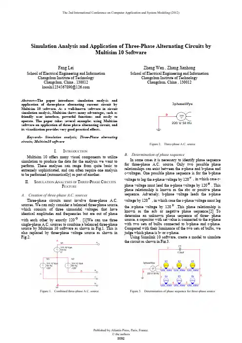
Multisim10中的三相交流电路仿真实验CAImultisim10
- 格式:doc
- 大小:194.50 KB
- 文档页数:7
1研究的意义三相电路是广泛应用于日常生活和生产中的电路系统。
因此,在电气实验和电气工程的教学和实验中,对三相电路的研究占据着重要的地位。
但是,由于三相电路的电压很高,可能会给实验者带来较大的危险。
同时,一些错误的实验可能会导致一些贵重的组件损坏造成不必要的财务支出。
因此,三相电路领域上的实验研究和电气专业实习难以实施。
如今,随着EMCElecfnic Design Aufmdion 技术的发展,三相电路的实验仅需要应用计算机软件来模拟电路系统就可以得到与实际情况相差无几的结果,而且还可以看到更直观的图像,同时可以避免因故障或人为的误操作造成元件损坏,节省实验成本,并提高实验者的安全。
目前,常用于电子电路设计及仿真的工具和辅助电路的仿真分析软件较多。
其中,Multisim 广泛应用于电子电路实验的视觉教学中,因其界面简单,易于操作。
所以相应电路的仿真研究已广泛应用于国内外大专院校。
且Multisim 软件中器件种类齐全,电路分析功能强大,可使用它进行三相电路的实验仿真。
2Multisim 软件随着传统的电路实验方法逐渐无法满足电子电气实验教学的需要,计算机辅助分析和设计已成为电子电气实验的重要发展趋势。
因此,Multisim 软件应运而生,成为广大电气专业研究领域的通用软件。
Multisim 是National Instruments (NI)推出的EWB 仿真软件。
它已经发展到Multisim14版本,并且已经成为电子电路实验设计的核心专业软件,如模拟电路和数字电路的仿真。
对于电路原理设计和电路功能仿真,Multisim 软件可提供数千种电路元件和全系列虚拟测试仪器,包括在实验室中使用的通用测量实验仪器(万用表、功能信号发生器、双迹线示波器),直流电源交流电源等,以及一般实验室中罕见或缺失的一些贵重的实验仪器(比如,测柱仪,数字信号发生器,逻辑分析仪,逻辑转换器,失真器,频谱分析仪和网络分析仪等)。

实验六 三相电路仿真实验一、实验目的1、 熟练运用Multisim 正确连接电路,对不同联接情况进行仿真;2、 对称负载和非对称负载电压电流的测量,并能根据测量数据进行分析总结;3、 加深对三相四线制供电系统中性线作用的理解。
4、 掌握示波器的连接及仿真使用方法。
5、 进一步提高分析、判断和查找故障的能力。
二、实验仪器1.PC 机一台 2.Multisim 软件开发系统一套 三、实验要求1.绘制出三相交流电源的连接及波形观察 2.学习示波器的使用及设置。
3.仿真分析三相电路的相关内容。
4.掌握三瓦法测试及二瓦法测试方法 四、原理与说明1、负载应作星形联接时,三相负载的额定电压等于电源的相电压。
这种联接方式的特点是三相负载的末端连在一起,而始端分别接到电源的三根相线上。
2、负载应作三角形联接时,三相负载的额定电压等于电源的线电压。
这种联接方式的特点是三相负载的始端和末端依次联接,然后将三个联接点分别接至电源的三根相线上。
3、电流、电压的“线量”与“相量”关系测量电流与电压的线量与相量关系,是在对称负载的条件下进行的。
画仿真图时要注意。
负载对称星形联接时,线量与相量的关系为: (1)P L U U 3= (2)P L I I =负载对称三角形联接时,线量与相量的关系为:(1)P L U U = (2)P LI I 3=4、星形联接时中性线的作用三相四线制负载对称时中性线上无电流,不对称时中性线上有电流。
中性线的作用是能将三相电源及负载变成三个独立回路,保证在负载不对称时仍能获得对称的相电压。
如果中性线断开,这时线电压仍然对称,但每相负载原先所承受的对称相电压被破坏,各相负载承受的相电压高低不一,有的可能会造成欠压,有的可能会过载。
五、实验内容及参考实验步骤(一)、建立三相测试电路如下:图1 三相负载星形联接实验电路图1.接入示波器:测量ABC三相电压波形。
并在下表中绘出图形。
Timebase:_________/DIV 三相电压相位差:φ=__________。
实验六三相电路仿真实验、实验目的1、熟练运用MUltiSim正确连接电路,对不同联接情况进行仿真;2、对称负载和非对称负载电压电流的测量,并能根据测量数据进行分析总结;3、加深对三相四线制供电系统中性线作用的理解。
4、掌握示波器的连接及仿真使用方法。
5、进一步提高分析、判断和查找故障的能力。
二、实验仪器1. PC机一台2. MUItiSim软件开发系统一套三、实验要求1.绘制出三相交流电源的连接及波形观察2 •学习示波器的使用及设置。
3•仿真分析三相电路的相关内容。
4 .掌握三瓦法测试及二瓦法测试方法四、原理与说明1、负载应作星形联接时,三相负载的额定电压等于电源的相电压。
这种联接方式的特点是三相负载的末端连在一起,而始端分别接到电源的三根相线上。
2、负载应作三角形联接时,三相负载的额定电压等于电源的线电压。
这种联接方式的特点是三相负载的始端和末端依次联接,然后将三个联接点分别接至电源的三根相线上。
3、电流、电压的“线量”与“相量”关系测量电流与电压的线量与相量关系,是在对称负载的条件下进行的。
画仿真图时要注负载对称星形联接时,线量与相量的关系为:(1) U L='3U P(2) I L=I P负载对称三角形联接时,线量与相量的关系为:(2)1 L = 3I P(I) U L =U P4、星形联接时中性线的作用三相四线制负载对称时中性线上无电流,不对称时中性线上有电流。
中性线的作用是能将三相电源及负载变成三个独立回路,保证在负载不对称时仍能获得对称的相电压。
如果中性线断开,这时线电压仍然对称, 但每相负载原先所承受的对称相电压被破坏,各相负载承受的相电压高低不一,有的可能会造成欠压,有的可能会过载。
五、实验内容及参考实验步骤 (一)、建立三相测试电路如下三相电压相位差: φ =(二)、三相对称星形负载的电压、电流测量(1) 使用MUItiSim 软件绘制电路图1,图中相电压有效值为 220V 。
Simulation Analysis and Application of Three-Phase Alternating Circuits byMultisim 10 SoftwareFang LeiSchool of Electrical Engineering and InformationChangchun Institute of Technology Changchun, China , 130012 Zheng Wen , Zhang JianhongSchool of Electrical Engineering and InformationChangchun Institute of Technology Changchun, China , 130012Abstract —The paper introduces simulation analysis and application of three-phase alternating current circuit by Multisim 10 software. As a well-known software in circuit simulation analysis, Multisim shows many advantages, such as friendly user interface, powerful functions and easily to operate. The paper takes several examples using Multisim software on application of three phase alternating circuit, and its visualization provides very good practical effects.Keywords- Simulation analysis; Three-Phase alternating circuits; Multisim10 softwareI. I NTRODUCTIONMultisim 10 offers many visual components to utilize simulation to produce the data for the analysis we want to perform. These analyses can range from quite basic to extremely sophisticated, and can often require one analysis to be performed (automatically) as part of another. II.S IMULATION A NALYSES OF T HREE -P HASE C IRCUITSF EATUREA. Creation of three-phase A.C. sourcesThree-phase circuits must involve three-phase A.C. sources. We can only consider a balanced three-phase source, which consists of three sinusoidal voltages that have identical amplitudes and frequencies but are out of phase with each other by exactly 120. [1]We can use three single-phase A.C. sources to combine a balanced three-phase source by Multisim 10 software as shown in Fig.1. This is also replaced by three-phase voltage source as shown inFig.2.Figure 1.Combined three-phase A.C. sourceFigure 2. Three-phase A.C. sourceB. Determination of phase sequenceIn some cases it is necessary to identify phase sequence for three-phase A.C. source. Only two possible phase relationships can exist between the a-phase and b-phase and c-voltages. One possible phase sequence is for the b-phase voltage to lag the a-phase voltage by 120, in which case c-phase voltage must lead the a-phase voltage by 120. This phase relationship is known as the abc or positive phase sequence. Adversely, b-phase voltage leads the a-phase voltage by 120, in which case the c-phase voltage must lagthe a-phase voltage by 120.This phase relationship is known as the acb or negative phase sequence.[2] To determine an unknown phase sequence of three- phase source, a capacitor with set value is connected to the a-phase with two sets of bulbs connected to b-phase and c-phase. Compared with their luminance of the two sets of bulbs, we judge which phase is b- or c-phase.Using Simulink 10 software, create a model to simulate the circuit as shown in Fig.3.Figure 3. Determination of phase sequence for three-phase sourceThe simulate result shows the phase with more brilliant light is b-phase and the rest phase is c-phase.C. Analysis of three-phase A. C. circuit features on load There are two ways of interconnecting three-phase load which is either a wye(Y) or a delta (Δ). Fig.4 shows simulation circuit of three-phase balanced loads with each phase two lamps series connection in a wye configuration with neutral conductor. The simulation circuit of three-phase balanced or unbalanced loads (Δconnected) with two or more lamps series connection is shown in Figure5.Figure 4. Simulation circuit of three-phase balanced loads in a wyeconfiguration with neutral conductorFigure 5. Simulation circuit of three-phase balanced loads in a deltaconfiguration with neutral conductorThe simulation results of three-phase balanced or unbalanced loads (Y-connected) with two or more lamps series connection in the case of connection and disconnection of neutral conductor show as follows below in Table.1(see page 3). According to these simulation data, we derive that in these cases each line-to-line voltage is balanced with neutral conductor or without neutral conductor , line-to-neutral voltage and current are balanced with neutral conductor, the magnitude of the line-to-line voltage is √3 times the magnitude of the line-to-neutral voltage and neutral node without neutral conductor is offset in the case of unbalanced loads.The simulation results of three-phase balanced or unbalanced loads (Δ-connected) with three or more lamps series connection is shown in Table.2. (see page 3). From simulation result, we derive that line voltage, line current and phase current are balanced when loads are balanced, and the magnitude of line current is √3 times the magnitude of the phase current, and line current and phase current are unbalanced in the case of unbalanced loads.Thus, there are many three-phase AC circuits models built by multisim 10 in order to perform the result same as the real experiment.D. Measurement of three-phase powerWe measure total three-phase power by three power meters means which is shown in Fig6. After assuming motor parameter R1,R2 and R3 as 200, the sum of three power meter shown is 726.111, which is 3 times the show data of single power meter. Two- meters method can be used in some cases. We select three-phase motor as load shown in Fig.7. When the simulation switch button closes, the analysis is run and we read the data from power meter. The sum of data two meter shown is 726.09W, which is the total power consumed by three-phase motor and power factor of three-phase motor is 0.867 [3].Above two methods both adapt for measuring the total power of three-phase circuits. The three-phase motor can be replaced by other loads.Figure 6. Three-meters method for measurement of three-phase powerFigure 7. Two-meters method for measurement of three-phase powerIII.S UMMARIESMultisim 10 simulation software on computer can provide the all kinds of design models to achieve test data and test images for principle experiments and expanded experiments. In addition to get the correct results,it can also be used for development and study of the experiment. The simulation results can determine whether the circuit design to achieve the desired goal to improve the students the analysis and solving problem skills. Meanwhile, Multisim 10 simulation software using computer as an experiment platform for different types of experiments, the laboratory can decrease the costs for construction and consumed raw materials and increase the operating efficiency because the components and apparatus used in the experiments are not limited..TABLE I. S IMULATION DATA FOR THREE-PHASE LOADS(Y- CONNECTED)With neutral conduct-or Lamps connectionmodeU AB(V)U BC(V)U CA(V)U A(V)U B(V)U C(V)I A(A)I B(A)I C(A)I N(A)U NN′(V) Each phase with twolamps seriesconnection381 381 381 220 220 220 0.764 0.764 0.764 0 \Phases with two-three-two seriesconnection381 381 381 220 220 220 0.764 0.509 0.764 0.255 \A-phase is brokenunder abovecondition381 381 381 220 220 220 0 0.509 0.764 0.674 \With no neutral conduct-or Each phase with twolamps seriesconnection381 381 381 220 220 220 0.764 0.764 0.764 \ 0Phases with two-three-four seriesconnection381 381 381 178.3 232.6 255.5 0.619 0.538 0.444 \ 0.019A-phase is brokenunder abovecondition381 381 381 331.1 163.3 217.7 0 0.378 0.378 \ 113.3A-phase is short(same as abovecondition)381 381 381 0 381 381 1.341 0.882 0.662 \ 220TABLE II. S IMULATION DATA FOR THREE-PHASE LOADS(Δ-CONNECTED)Lamps connection mode U AB(V)U BC(V)U CA(V)I A(V)I B(V)I C(V)I AB(A)I BC(A)I CA(A)Each phasewith threelamps seriesconnection380.998 380.998 380.995 1.528 1.528 1.528 0.882 0.882 0.882Phases withthree-four-three seriesconnection381.031 380.989 380.992 1.528 1.341 1.341 0.882 0.661 0.882Phases withfour-three-four seriesconnection381.031 381.020 381.024 1.146 1.341 1.341 0.662 0.882 0.662R EFERENCES[1]James W. Nilsson; Susan A. Riedel. Introductory Circuits forElectrical and Computer Engineering, Publishing of Electronics Industry [M], 2002, PP:310-312[2]NI Dian; HUANG Pei-gong. Application of Multisim 10 in theDesign of Electronic Circuit ,Publishing of Electronics Industry[M], 2007. PP259-261. [3]National Instruments Corporation. Multisim 10 User Guide [M]2007.01, PP461-463。

第四章三相电路§4-6应用Multisim软件进行三相电路仿真实验一、实验目的(1)通过仿真实验了解三相负载的星型连接。
(2)通过仿真实验掌握负载星形连接时的线电压与相电压之间的关系。
(3)通过仿真实验进一步理解三相四线制的中线在负载不对称时的作用。
二、实验原理及说明对称三相负载做星形连接时,负载的相电压与相电流均对称,负载的线电压是相电压的倍,负载的线电流与相电流相等,中线电流为零。
三相负载星型连接,有中线时,不论负载对称与否,负载中性点的电位与电源中性线的电位相同。
负载的端电压保持对称关系,线电压有效值是相电压有效值的倍,即无中性线时,负载对称时与有中性线时相同,负载不对称时,负载中性点的电位将与电源中性线的电位不同。
各相负载的端电压不再保持对称关系。
33pl U U 3三、实验内容及步骤(1)在Multisim软件中按图建立实验电路。
在电路中接入两只开关,J1用来控制中性线的通断,使电路成为三相三线制和三相四线制连接;J2用来控制A相负载的切换,使电路成为对称负载与不对称负载连接电路。
电路中接入四只交流电流表分别用来测量各相的线电流和中线电流。
接入六只电压表分别用来测量相电压和三根端线之间的线电压。
(2)分别按空格键和A键,闭合开关J1和J2,使电路成为三相四线制对称电路。
单击仿真开关,运行仿真,测量相电压、线电压、线电流、中线电流,并将所得数据记录在表中。
项目线电流(A)线电压(V)相电压(V)中线电流(A)IAIBICUABUBCUCAUAUBUCIN对称负载(J2闭合)有中线(J1闭合)无中线(J1断开)不对称负载(J2断开)有中线(J1闭合)无中线(J1断开)(3)按空格键,断开开关J1,使电路成为三相三线制对称电路。
单击仿真开关,运行仿真,测量相电压、线电压、线电流,并将所得数据记录在表中。
(4)按A键,断开开关J2,按空格键,闭合开关J1,使电路成为三相四线制不对称电路。

Multisim三相电路仿真实验————————————————————————————————作者:————————————————————————————————日期:2--3 实验六 三相电路仿真实验一、实验目的1、 熟练运用Multisim 正确连接电路,对不同联接情况进行仿真;2、 对称负载和非对称负载电压电流的测量,并能根据测量数据进行分析总结;3、 加深对三相四线制供电系统中性线作用的理解。
4、 掌握示波器的连接及仿真使用方法。
5、 进一步提高分析、判断和查找故障的能力。
二、实验仪器1.PC 机一台 2.Multisim 软件开发系统一套 三、实验要求1.绘制出三相交流电源的连接及波形观察 2.学习示波器的使用及设置。
3.仿真分析三相电路的相关内容。
4.掌握三瓦法测试及二瓦法测试方法 四、原理与说明1、负载应作星形联接时,三相负载的额定电压等于电源的相电压。
这种联接方式的特点是三相负载的末端连在一起,而始端分别接到电源的三根相线上。
2、负载应作三角形联接时,三相负载的额定电压等于电源的线电压。
这种联接方式的特点是三相负载的始端和末端依次联接,然后将三个联接点分别接至电源的三根相线上。
3、电流、电压的“线量”与“相量”关系测量电流与电压的线量与相量关系,是在对称负载的条件下进行的。
画仿真图时要注意。
负载对称星形联接时,线量与相量的关系为: (1)P L U U 3=(2)P L I I =负载对称三角形联接时,线量与相量的关系为:(1)P L U U = (2)P LI I 3=4、星形联接时中性线的作用三相四线制负载对称时中性线上无电流,不对称时中性线上有电流。
中性线的作用是能将三相电源及负载变成三个独立回路,保证在负载不对称时仍能获得对称的相电压。
--4 如果中性线断开,这时线电压仍然对称,但每相负载原先所承受的对称相电压被破坏,各相负载承受的相电压高低不一,有的可能会造成欠压,有的可能会过载。
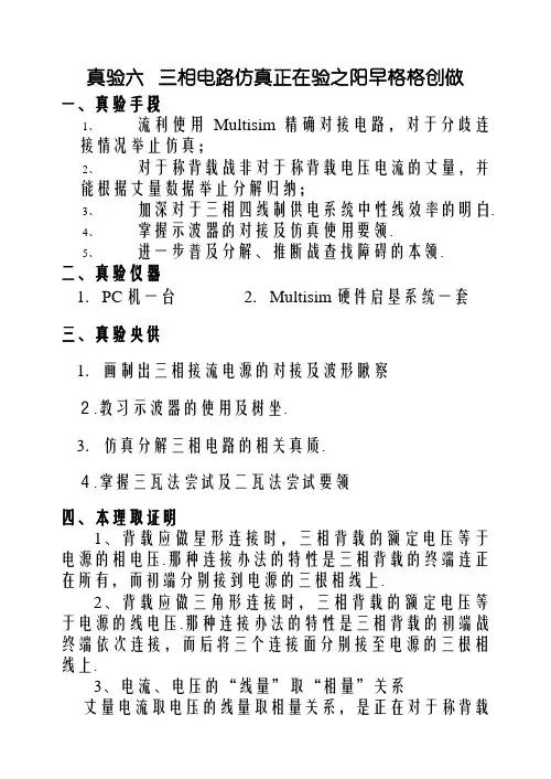
真验六三相电路仿真正在验之阳早格格创做一、真验手段1、流利使用Multisim精确对接电路,对于分歧连接情况举止仿真;2、对于称背载战非对于称背载电压电流的丈量,并能根据丈量数据举止分解归纳;3、加深对于三相四线制供电系统中性线效率的明白.4、掌握示波器的对接及仿真使用要领.5、进一步普及分解、推断战查找障碍的本领.二、真验仪器1.PC机一台2.Multisim硬件启垦系统一套三、真验央供1.画制出三相接流电源的对接及波形瞅察2.教习示波器的使用及树坐.3.仿真分解三相电路的相关真质.4.掌握三瓦法尝试及二瓦法尝试要领四、本理取证明1、背载应做星形连接时,三相背载的额定电压等于电源的相电压.那种连接办法的特性是三相背载的终端连正在所有,而初端分别接到电源的三根相线上.2、背载应做三角形连接时,三相背载的额定电压等于电源的线电压.那种连接办法的特性是三相背载的初端战终端依次连接,而后将三个连接面分别接至电源的三根相线上.3、电流、电压的“线量”取“相量”关系丈量电流取电压的线量取相量关系,是正在对于称背载的条件下举止的.画仿真图时要注意.背载对于称星形连接时,线量取相量的关系为: (1)P L U U 3= (2)P L I I =背载对于称三角形连接时,线量取相量的关系为: (1)P L U U = (2)P L I I 3= 4、星形连接时中性线的效率三相四线制背载对于称时中性线上无电流,分歧过失称时中性线上有电流.中性线的效率是能将三相电源及背载形成三个独力回路,包管正在背载分歧过失称时仍能赢得对于称的相电压.如果中性线断启,那时线电压仍旧对于称,但是每相背载本先所启受的对于称相电压被损害,各相背载启受的相电压下矮纷歧,有的大概会制成短压,有的大概会过载. 五、真验真质及参照真验步调 (一)、修坐三相尝试电路如下:图1 三相背载星形连接真验电路图1.接进示波器:丈量ABC 三相电压波形.并正在下表中画出图形.Timebase :_________/DIV 三相电压相位好:φ=__________.(二)、三相对于称星形背载的电压、电流丈量(1)使用Multisim 硬件画制电路图1,图中相电压灵验值为220V.(2)精确接进电压表战电流表,J1挨启,J2 、J3关合,丈量对于称星形背载正在三相四线制(有中性线)时各线电压、相电压、相(线)电流战中性线电流、中性面位移电压.记进表1中.(3)挨启启关J2,丈量对于称星形背载正在三相三线制(无中性线)时电压、相电压、相(线)电流、中性线电流战中性面位移电压,记进表1中.压、电流“线量”取“相量”的关系.论断:(三)、三相分歧过失称星形背载的电压、电流丈量(1)精确接进电压表战电流表,J1关合,J2 、J3关合,丈量分歧过失称星形背载正在三相四线制(有中性线)时各线电压、相电压、相(线)电流战中性线电流、中性面位移电压.记进表2中.(2)挨启启关J2,丈量分歧过失称星形背载正在三相三线制(无中性线)时各线电压、相电压、相(线)电流、中性线电流战中性面位移电压,记进表2中.表2 三相分歧过失称星形背载的电压、电流中性线的主要效率,由此得出为什么中性线不允许加拆熔断器的本果?正在背载分歧过失称的时间依旧赢得的对于称的相电压.论断:(四)、三相电路星形联结尝试功率:1、画出如下图:2.接进功率表测出每相功率:=A P,=B P_________,=P_________,C总功率P总=.3.正在B相接进电流表测出I B=,估计总功率P总=.U____,相电压战线4.丈量相电压=A U____,线电压=AB电压关系:________.5、利用上头电路图,修坐二瓦法尝试电路并考证总功率二瓦法接进瓦特表,仿真测出每相功率:P1=,P2=_________,总功率P总=.(五)、三相对于称星形背载障碍分解(1)三相对于称星形背载,将U相断路,即J3挨启,J1挨启、J2关合,丈量四线制时各线电压、相电压、相(线)电流战中性线电流、中性面位移电压.记进表3中.(2)上述背载中,挨启启关J2,丈量三线制U相断路时各线电压、相电压、相(线)电流战中性线电流、中性面位移电压,记进表3中.(3)思索:背载对于称,星形连接,无中线,若有一相背载爆收断路障碍,对于其余二相背载的效率怎么样?丈量时如爆收微弱的缺面,那主假如硬件自己的本果,那样小的缺面对于截止并不太大的效率.六.真验报告央供1.根据本质支配,仔细写出真验步调.2.挨印并分解各仿真截止.七.预习央供1.预习课本中的相关真质.2.阅读并认识本次真验的真质.。

2019年4月总第311期ISSN1672-1438CN11-4994/T 作者简介:兰海燕,工程硕士,讲师。
在高职高专院校电力类或电力相关专业教学中,讲练结合是非常必要的。
在三相交流电路的学习过程中,三相三线制、三相四线制、负载平衡、负载不平衡等多种情况对于学习中的学生来说,有时理解得不是那么透彻,或者理论和实际情况不容易结合到一起。
所以本文讨论这一部分内容理论与实际相结合的教学研究[1]。
本仿真实验基于学生已学过相应理论基础的情况下进行。
1 构建实验电路为了方便地模拟各种实验情况,这里采用9个独立的SPST 开关J1~J9控制九盏灯泡X1~X9;电压采取三相星型电源,380/220 V ,50 Hz 。
考虑到不同实验条件下灯泡耐压及功耗问题,这里选取虚拟灯泡元件LAMP-VIRTUAL ,并设置最大额定电压400 V ,最大额定功率15 W ,三相电路如图1所示。
图1 三相实验电路2 测量实验数据本次实验共有以下几种情况,三相四线制Y0接平衡负载,三相三线制Y 接平衡负载,三相四线制Y0接不平衡负载,三相三线制Y 接不平衡负载。
不平衡负载考虑包含短路、断路的特殊情况。
实验需要测量三相线电压、负载相电压、负载线电流、中线电流和中点电压。
图2为三相四线制Y0接平衡负载情况下所有万用表的接线及读数。
双击仪表,显示读数,然后按以下顺序放置,便于读数。
左侧3块仪表(XMM1~XMM3)为线电流,中间3块表(XMM5~XMM7)为线电压,右侧3块表(XMM8~XMM10)为相电压。
中间及右侧最下面2块表分别为中线电流(XMM4)和中点电压(XMM11)。
不同万用表需要根据调至不同的测量档位。
图2 三相四线制Y0接平衡负载需要注意的是,当稍后测量三相三线制不同负载的时候,需要去掉中线,即需要去掉XMM4所在的导线,而不能去掉XMM11所在的导线。
因为这2块表XMM11是测量电压,其内阻非常大,本来这根线就是断路的情况。
基于Multisim10的接触器仿真设计与实现王晗【摘要】三相电动机正反转控制电路是电工电子实验教学中的一个重要内容,而接触器是本实验中的重中之重.通过应用Multisim10仿真软件实现了接触器的仿真,实验证明结果准确.这对于危险性电工电子实验的预习提供了新的方法,实现了逼真模拟操作,对高校学生实际操作能力的提高有重大的意义,同时减少了实验中的损耗.【期刊名称】《实验技术与管理》【年(卷),期】2010(027)003【总页数】4页(P82-84,87)【关键词】接触器;电路仿真;Multisim10【作者】王晗【作者单位】广东工业大学实验教学部,广东,广州,510006【正文语种】中文【中图分类】TM572;TP393.01三相电路在电力系统应用最为广泛,多数负载一般都采用三相制。
三相电机控制电路是日常生产中应用广泛的电路系统,也是高校电工电子实训课程教学中的一项重要内容,它对于本科层次机电类学生的实际动手能力的提高以及相关专业课程的学习有重大影响。
三相交流电的电压较高,因此针对三相电机正反转控制电路的相关实验和实训过程都存在一定的危险,此外有些故障性实验,诸如负载短路、自锁现象等都难以进行[1]。
由于针对三相电机正反转控制电路的仿真较为复杂,一些仿真软件对于此类电路的仿真比较抽象,尤其是其中的电流接触器没有通用元器件,很难形象描述,所以目前大部分高校学生针对三相电机正反转控制电路的预习方法还仅仅限于课前的报告抄写。
这种方法对于学生掌握相关知识,训炼实际动手能力是不利的。
从创新性人才培养的角度考虑,应该给予学生更加逼真的仿真环境,提高预习效果,以便在真实的实验环境中敢于大胆动手,积极主动,从而加深对知识的理解,掌握操作技能。
本文应用Multisim10.0软件实现三相电机正反转控制电路实验的真实场景,学生可以在高仿真环境下接线实验,查找问题,为真实环境下的接线操作打好基础,减少实验器件的损坏率。
Multisim仿真实验:三相交流电路姓名:马骁班级:电气1341 学号:17一、实验目的1. 学习用电设备三相供电线路的正确联接方法。
了解不正确连接对负载工作的影响,了解三相四线制供电线路中中线的作用。
2.验证三相对称负Y接和△接时,线电压与相电压、线电流和相电流之间的关系。
3.掌握三相不对称负载Y接和△接时,各线电压、相电压、线电流、相电流的变化情况。
二、实验原理1.三相交流电路主要是由三相电源、三相负载与三线输电线路三部分组成。
对称三相电源是由3个同频率、等幅值、初相依次滞后120度的正弦电压源链接成星(Y)形或三角(△)形组成的电源。
3个阻抗连接成Y形(或△形)就构成星形(或三角形)负载,只有当3个阻抗相等时,才构成对称三相负载。
将三相电源与三相负载连接可形成三相四线制或三相三线制的三线电路。
2. 负载应作星形联接时,三相负载的额定电压等于电源的相电压。
这种联接方式的特点是三相负载的末端连在一起,而始端分别接到电源的三根相线上。
负载应作三角形联接时,三相负载的额定电压等于电源的线电压。
这种联接方式的特点是三相负载的始端和末端依次联接,然后将三个联接点分别接至电源的三根相线上。
3.电流、电压的“线量”与“相量”关系:负载对称星形联接时,线量与相量的关系为:(1)UL=Up (2)IL=Ip负载对称三角形联接时,线量与相量的关系为:(1)UL=Up (2)IL=Ip4、星形联接时中性线的作用三相四线制负载对称时中性线上无电流,不对称时中性线上有电流。
中性线的作用是能将三相电源及负载变成三个独立回路,保证在负载不对称时仍能获得对称的相电压。
如果中性线断开,这时线电压仍然对称,但每相负载原先所承受的对称相电压被破坏,各相负载承受的相电压高低不一,有的可能会造成欠压,有的可能会过载。
四、实验内容与结果分析1.制作星形三相四线制电路2.三相四线制星形(Y)负载的三相电路仿真实验搭建如图(1)所示的三相四线制星形(Y)对称负载的三相仿真电路图。
详解Multisim10仿真实验步骤详解Multisim 10仿真实验步骤一、实验目的熟悉并掌握Multisim10对单片机的仿真过程。
加深对单片机硬件以及软件理论知识的理解。
二、实验原理1、Multisim10美国国家仪器公司下属的ElectroNIcs Workbench Group在今年年初发布了Multisim 10。
新版的Multisim10,加入了MCU模块功能,可以和8051等单片机进行编程联调,该软件元件丰富,界面直观,虚拟仪器的逼真度达到了让人相当高的程度,是电子设计、电路调试、虚拟实验必备良件。
工程师们可以使用Multisim 10交互式地搭建电路原理图,并对电路行为进行仿真。
Multisim提炼了SPICE仿真的复杂内容,这样工程师无需懂得深入的SPICE技术就可以很快地进行捕获、仿真和分析新的设计,这也使其更适合电子学教育。
通过Multisim和虚拟仪器技术,PCB设计工程师和电子学教育工作者可以完成从理论到原理图捕获与仿真再到原型设计和测试这样一个完整的综合设计流程。
下面将简单介绍一下Multisim10刚加进来的MCU模块的使用方法。
双击桌面上的multisim10图标,由于软件比较大,需要等待一定的时间才能进入以下界面(图一):图一Multisim10界面和Office工具界面相似,包括标题栏、下拉菜单、快捷工具、项目窗口、状态栏等组成。
标题栏用于显示应用程序名和当前的文件名。
下拉菜单提供各种选项。
快捷工具分为:文件工具按钮,器件工具按钮,调试工具按钮,这些按钮在下拉菜单中都有,并经常用到,现在放在工具栏里是为了方便使用。
项目窗口中的电路窗口是用来搭建电路的,Design Toolbox工具栏是用来显示全部工程文件和当前打开的文件。
状态栏用于显示程序的错误和警告,如果有错误和警告那还还需要重新修改程序。
直到没有错误为止才能正常加载程序。
在电路窗口的空白处点击鼠标右键,将出现如下菜单(图二):图二菜单包括:放置元件(place component)、连接原理图(place schematic)、放置图形(place graphic)、标注(place comment)等,这里我们最常用到的只有第一个放置元件:点击菜单中第一个选项或者按“CTRL+W”会出现以下元器件选择对话框(图三):图三在Group中选择我们需要的器件的类别,在Family中选择我们需要的器件,点击“OK”即可。