港迪制动单元说明书
- 格式:pdf
- 大小:679.79 KB
- 文档页数:26

HM5070CA门座起重机说明书江阴市华澄实业有限公司2007年8月一、总则:HM5070CA门座起重机为船厂用起重设备。
可供船厂在码头或船坞边作安装和起吊作业。
为同时适应我国南北方的温度、湿度和风力状况等自然条件,起重机的设计和校核均按我国现行国家标准《起重机设计规范》和《起重机安全规程》中的要求执行,以保证本起重机在各船厂都可以正常工作。
本机设置在轨距为10.5米的轨道上运行,门架的基距为12米。
本机采用滑触线供电装置电源为三相380V50HZ交流电源。
为减少风载荷,本起重机采用无缝钢管组成的直臂架,并可以在变幅时使吊载近似地沿水平线移动,从面使动作平稳可靠,节省变幅功率。
为提高工作效率,本起重机设有主、副起升机构。
加上起重机可以任意角度回转及与起升或变幅联合动作,使吊载可以最短的移动路线完成作业,达到较高效率作业目的。
行走机构为工作性机构,供起重机移位或吊载工况下行走。
本机门座内的净空高度为8米,足供大型载货卡车安全通过。
起重机总体性能表行走轨道/最大轮压:QU80 250KN/轮二、机构1.起升机构主、副起升机构均由变频电动机、制动器(为确保安全采用两套制动器)、减速箱、卷筒等组成。
卷筒轴端装有限位开关以限制起升高度和深度。
高度限位开关调整在行走轨道面以上50m,轨道面以下(主钩:-12m,副钩:-10m)时作用,当一个方向限位动作时,起升只能向极限的反方向动作。
本机构的起重能力为50吨吊钩和12吨副吊钩,分别在35m和70m幅度内可分别起吊50T和12T载荷,在司机室墙上安装有载荷指示,当相应幅度起重量接近规定值时发出预警信号,当载荷超出5%时自动切断起升方向电源,只能作下降动作。
超载限制器为安装在人字架横梁处的三芯滑轮中的压式传感器,幅度传感器安装在臂架下铰处。
2、变幅机构变幅机构用钢丝绳变幅驱动直臂架,由电动机、减速箱、制动器和卷筒等组成。
为确保安全采用两套制动器,每套制动器都能支持住臂架。
盘式制动器使用说明书盘式制动器使用说明书盘式制动器使用说明书目录一、性能与用途.1二、结构特征与工作原理..1三、安装与调整..4四、使用与维护..9五、润滑...12六、特别警示...13七、故障原因及处理方法...12附图1:盘式制动器结构图...15附图2:盘形闸结盘式制动器使用说明书目???录一、性能与用途 (1)二、?结构特征与工作原理 (1)三、?安装与调整 (4)四、?使用与维护 (9)五、?润滑? (12)六、特别警示 (13)七、?故障原因及处理方法? (12)附图1:盘式制动器结构图 (15)附图2:盘形闸结构图 (16)附图3:?制动器限位开关结构图 (17)附图4:?盘式制动器的工作原理图 (18)附图5:?盘式制动器安装示意图 (19)附图6:?制动器信号装置安装示意图 (20)一、性能与用途盘式制动器是靠碟形弹簧产生制动力,用油压解除制动,制动力沿轴向作用的制动器。
盘式制动器和液压站、管路系统配套组成一套完整的制动系统。
适用于码头缆车、矿井提升机及其它提升设备,作工作制动和安全制动之用。
其制动力大小、使用维护、制动力调整对整个提升系统安全运行都具有重大的影响,安装、使用单位必须予以重视,确保运行安全。
盘式制动器具有以下特点:1、制动力矩具有良好的可调性;2、惯性小,动作快,灵敏度高;3、可靠性高;4、通用性好,盘式制动器有很多零件是通用的,并且不同的矿井提升机可配不同数量相同型号的盘式制动器;5、结构简单、维修调整方便。
二、结构特征与工作原理1、盘式制动器结构(图1)盘式制动器是由盘形闸(7)、支架(10)、油管(3)、(4)制动器信号装置(8)、螺栓(9)、配油接头(11)等组成。
盘形闸(7)由螺栓(9)成对地把紧在支架(10)上,每个支架上可以同时安装1、2、3、4对甚至更多对盘形闸,盘形闸的规格和对数根据提升机对制动力矩的大小需求来确定。
2、盘形闸结构(图2)盘形闸由制动块(1)、压板(2)、螺钉(3)、弹簧垫圈(4)、滑套(5)、碟形弹簧(6)、接头(7)、组合密封垫(8)、支架(9)、调节套(10)、油缸(11)、油缸盖(12)、盖(13)、放气螺栓(17)、放气螺钉(19)、O形密封圈(20)、Yx密封圈(21)、螺塞(22)、Yx密封圈(23)、压环(24)、活塞(25)、套筒(26)、联接螺钉(27)、键(28)及其它副件、标件等组成。

MOTORR/L1S/L2T/L3U V WIMSymbol for groundingBraking resistorCircuit breaker for wiring(MCCB)T erminal block for main circuitPower sourceMotorFunctions of Terminals for Main CircuitIMCircuit breaker for wiring(MCCB)MotorBraking resistorL1L2P/DB+N-DB-U V W3-phase 400V type 0.75 to 15kWSpecification of potentiometer for frequency setting:select a potentiometer of “10 kΩ, 1/4 W or higher” rating. Relay output specification:1c contact (contact capacity 230V AC, 0.3A; 30V DC 0.3A resistive load).Open-collector Output specification: max. rating 50 VDC/50 mA.Please refer to the User Manual for the SOURCE status terminal arrangement diagram and the functions of various terminals.Terminal No.Terminal NameExplanation of terminal functionR/L1,S/L2,T/L3U,V,W P/DB+,DB-N-×2Power supply for Main circuit Inverter outputBraking resistor connection Internal DC voltage (negative)GroundFor 1-phase 200 V type, connect to terminal L1 and L2.Connect to 3-phase motor.Connect to braking resistor.Negative terminal of internal DC voltage.Ground terminal.1-phase 200 V: ground resistance 100Ω or less 3-phase 400 V: ground resistance 10Ω or less Ground the neutral of power source.VF200 SERIESPanasonic Industrial Devices SUNX Suzhou Co., Ltd.No.97, Huoju Road, New District Suzhou, Jiangsu province, ChinaSINKSOURCESW1SW2SW3SW4SW5NONC COMRelay output(TR1、TR2)Specifications are subject to change without notice.Please contact...........Simple Vector Control InverterHigh-efficiency Operation, Outstanding PerformanceCommon terminalsCommon terminalsAnalog output (Note)4 to 20mA 0 to 20mA 4 to 20mA0 to 20mA4 to 20mA 0 to 20mA(Note)(Note)RS485communication terminal(0 to 10V)0 to 5V 0 to 10V0 to 5V 0 to 10VRun /Stop Forward /ReverseNote) a built-in 200 Ω resistor should be set between terminal No.24 and a common terminal. If analog input signal of 4 to 20mA/0 to 20mA is used, external resistor connection can be eliminated by connecting terminal No.24 to No.14 or No.16. For external connection, it is recommended to use a resistor of 200 Ω, 1/4 W.All Rights Reserved Panasonic Industrial Devices SUNX Suzhou Co., Ltd. 2013■Telephone: +81-512-6843-2580 ■Facsimile: +81-512-6843-2590■No.97.Huoju Road, New District Suzhou, Jiangsu province, China P.R.215009Panasonic Industrial Devices SUNX Suzhou Co., Ltd.PowerfulTurntableInjection moldingmachineCopy parameters Operation panelcan be prolongedUse vector control to output higher torqueat low-speedNetworkEquip with standard RS485 SerialCommunication InterfaceCorresponding Functions forWire Winding MachinesToughIncorporate with Output Short-CircuitProtection CircuitsEquip with High-speed CurrentLimiting Protection function EasyApply large-scale operation panelto further improve the operabilityDetachable operation panelControl PanelComputerRS485 (Max. 500m)New Operation ModeDuring ONThe winding mode control function operates at the frequencies of atriangle wave as shown below.Repeated operation around the Winding SpindleSpinnerApply to most textile equipmentsin which inverters are used.During OFFVF200VF200VF200VF200CopyCopy11 kW(400V)15 kW(400V)5.5 kW(400V)7.5 kW(400V)2.2 kW(200V)2.2 kW(400V)3.7 kW(400V)0.2 kW(200V)0.4 kW(200V)0.75 kW(200V)1.5 kW(200V)0.75 kW(400V)1.5 kW(400V)Higher torque can be generated at low-medium speed (1Hz→150%) bymaking use of our Company’s original vector control technology. Equipmentswith great fluctuation in loads and requiring a sufficient starting torque, forexample conveyor belts and turntables on which there are large numbersof semi-finished products, can be operate smoothly. In addition, the vectorcontrol technology also plays a significant role in the operation of the cannedfoods caulking machines, punching machines, injection molding machines,as well as other machines that require low-speed torque. Inverter with highercapacity is not needed in this case, which contributes greatly to the reductionof cost and installation space.It is also equipped with auto-tuning function which can conduct simple andappropriate parameter settings thus giving a full play to the motor characteristic.Highly visible 7-segment large format display;Ease-to-use large volume knob;Easy recognizable operation key.Parameter can be easily copy to another unit.Have a dimension of 72mm×72mm, it is attractive even if it is mounted on the panel surface.Standard LAN cables (max. 5m), which can be bought easily from the market,are used to realize the connection between the operation panel andthe host. It has the characteristics of ease purchase and affordable price.31 unitsCan control up to 31 VF200 units via the RS485 serial communicationlines. VF200 is also installed with two protocols : Modbus-RTU andMEWTOCOL, that allow control, data collection/monitoring viacomputer or PLCs.The FP series PLCs produced by our Company support both Modbus-RTU and MEWTOCOL.Which can be connected directly to the touchscreen GT series to provide you with a convenientoperating environment. For example, you mayconduct various operations such as monitoring,setting and operation via the screen.·Random swing mode: can effectively prevent the accumulation ofwires at the same point·Winding Wire Length Stop Mode: it will automatically stop after thelength of the winding wire had accumulated to the specified value.·Pulse Input Controlled length Calculation Mode: easily indicate theaccumulated length of the winding wire, and the results can be transmitted.·Two-point Mode: the reference frequency can be ultimately changed toa secondary frequency with the smooth running of the winding wire.With built-in short-circuit protectioncircuitsFaultshort-circuitVF200 can detect an over-current resulting from a short circuit dueto a fault in the electric motor as a result of over-load, in this case,it will instantaneously disconnect the output to protect the circuit,therefore, you can rest assured that it is safe.VF200 will not trip and keep operating even if instantaneous over-current is caused by a change in loads, thus improve the productivity.It is also applicable to the rapid increase in the speed of a heavyturntable and the stirring of materials with a higher viscosity such asbread and noodles.TripOutput CurrentOutput Frequency Output FrequencyOutput CurrentUpperPeak ValueSettingFrequencyLowerPeak ValueStar/StopRandom ModeCommon ModeRandomly swing within thespecified rangeWastewater beingdischargedfrom canteenkitchensFlowmeter ①Filter Flowmeter ②4-20mAAnalog input4-20mAAnalog inputControl panelWater used forindustrial useControl terminals(①-③)0-10VAnalog outputFP-XAFPX-C30T AFPX-A21Main body Operation PanelUnit: mm3-phase 400 V input typeNote) The cooling fan is not mounted on 0.75 kW model.※Please process the mounting platebased on the dimensions of the panelcut-out.The appropriate thickness of the platePanel Cut-outDimensions ofPanel Cut-out (A View)1-phase 200 V input type Unit: mmNote) Cooling fan is not mounted on 0.2 kW~0.75 kW model.0.2, 0.4kW100 112 130 143 120 52.2kW130 143 130 143 5160InvertercapacityW1W H1H D Φd0.75, 1.5kW 100 112 130 143 51500.75, 1.5kW2.2,3.7kW5.5, 7.5kW11, 15kWInvertercapacityW1W H1H DΦd5557100130150112163143130130190143143203150150179179204 223 2652831-phase, 200 to 230V AC (proportional to power supply voltage)1-phase, 200 to 230V AC, 50/60 Hz±5% of rated input frequency0.2 to 2.2kW150% of rated output current for 1 minute+10% and –15% of rated input AC voltageOperation continues when voltage is above 165V AC.Operation continues for 15 ms when voltage drops below 165V AC.3-phase, 380 to 460V AC (proportional to power supply voltage)3-phase, 380 to 460V AC, 50/60 Hz±5% of rated input frequency0.75 to 15kW150% of rated output current for 1 minute+10% and –15% of rated input AC voltageOperation continues when voltage is above 323V AC.Operation continues for 15 ms when voltage drops below 323V AC.Rated VoltageNumber of phases,voltage and frequencyAllowable frequency fluctuationStandard output of applicablemotor (kW)Over-load Current RatingAllowable voltage fluctuationInstantaneous voltagedrop ride-through capabilityInputpowersupplyInputpowersupplyRated VoltageNumber of phases,voltage and frequencyAllowable frequency fluctuationStandard output of applicablemotor (kW)Over-load Current RatingAllowable voltage fluctuationInstantaneous voltagedrop ride-through capabilityRatedOutputRatedOutputNote 5: the AVF200-REM1 operation panel is applicable to both the 200V and 400V types.Composition of PLC5SpecificationsUse the small-sized PLC [FP-X] and VF200of Our Company to control the tank pump pressureDecompositiontankSetting tank Storage tankControl unit C30TAnalog I/O card(Mounting holes)(Mounting holes)Unit: mmUnit: mmC o n t r o lPID function Automatic tuningSlip compensation control Cooling fan ON/OFF controlCommunication functionB r a k i n gRegenerative braking torque DC braking O u t p u t s i g n a lAnalog outputOpen-collector outputRelay outputD i s p l a yOperation/control statusDetails of abnormality P r o t e c t i o nCurrent limit Trip (stop)Stall prevention functionE n v i r o n m e n tAmbient temperature and humidity Storage temperature and humidity Vibration Altitude LocationEnclosure Cooling methodNote 1: it is -10 to +40°C when multiple inverters are installed side-by-side.Frequency range Frequency display Frequency accuracy Frequency resolutionInverter control mode Carrier frequencyO p e r a t i o nStart/StopForward/Reverse run JOG operation Stop mode Reset function Start frequency Stop frequencyRide-through restart select Speed search Retry functionC o n t r o lFrequency setting signalFrequency/voltage characteristics Torque boostAcceleration/deceleration timeAcceleration/deceleration characteristics The 2nd function select Multi-speed frequency settingSkip frequency setting Upper frequency limit setting Lower frequency limit settingO u t p u t F r e q u e n c ySeries name: VF200Applicable motor capacity:002 :0.2 kW004 :0.4 kW 007 :0.75 kW 015 :1.5 kW022 :2.2 kW 037 :3.7 kW Voltage class: Panel type:12341-phase 200V type: 0.2 to 2.2kW; 3-phase 400V type: 0.75 to 15 kW055 :5.5 kW075 :7.5 kW 110 :11 kW150 :15 kW A VF200 007 2 □12342 for 1-phase 200 V type; 4 for 3-phase 400V typewithout marks: operation panelP: simple panelProduct Ordering SystemBias/gain frequency setting External stop function Automatic tuning of motor constant Available Available·Protocols : MEWTOCOL-COM/Modbus (RTU) (switchable)·Communication pattern: Half duplex Output functions: operation signal, arrival signal, overload alarm, frequency detection, abnormal reverse run signal Output functions: operation signal, arrival signal, overload alarm, frequency detection, Output voltage, internal DC voltage, setting frequency, communication station No., operation(setting value, measured value and output value), progress of automatic tuning, accumulative operation time and accumulative operation time of fanOvercurrent and overvoltage stall preventionIndoor areas free of corrosive gases, flammable gases, oil mist or dust PID control mode (optional)·Interface : RS485 serial communication·Communication speeds : 4800/9600/19200/38400 bps (switchable)·Maximum number of connected units: 31·Maximum transmission distance: 500 m (in total)·200 V 0.2 kW: 100% or higher; 0.4 kW: 80% or higher; 0.75 to 2.2 kW: 20% or higher ·400 V 0.75 to 15 kW: 20% or higher Operate at the frequency below stop frequency ·Braking torque level: 0 to 100 (20 steps adjustable)·Braking time: adjustable from 0.1 to 120 sOutput specification: 0 to 10V DC (max. 1 mA)Output function: output frequency and output current proportion (switchable)Output specification: max. rating 50V DC/50 mAalarm, current detection, timer OFF signal and output frequency/current proportion PWM signal (cycle: 1 ms) (switchable)Output specification: 1c contact (contact capacity 230 VAC, 0.3 A resistive load)abnormal reverse run signal alarm, current detection and timer OFF signal (switchable)Output frequency, linear speed display (switchable) and rotation directiontimes of timer, alarm type, control circuit terminal status (I/O signal), operation status, PID Specific symbol is indicated when the protection function is activated (the latest four abnormalities are stored.)Current limit can be set within 1 to 200% of rated output current.Instantaneous overcurrent (SC1-6) and abnormal temperature (OH)Overcurrent (OC1-3), overload and electronic thermal relay (OL), undervoltage (LU),overvoltage (OU1-3), cooling fan fault (FAN), external fault (AU), operation fault (OP) and CPU fault (CPU)-10 to +50°C (Note 1) (without freezing) and below 90%RH (without condensation)-25 to +65°C and below 95%RH 5.9m/s 2 (0.6G) or lower 1000m or lowerIP20 cabinet-mounted·400 V 0.75 kW: self-cooling; 1.5 to 15 kW: air-cooling·200 V 0.2 to 0.75 kW: self-cooling; 1.5 to 2.2 kW: air-cooling Bias frequency: adjustable from -99 to 250%Gain frequency: adjustable from 0 to 500%External fault stop/coast-to-stop (switchable)·Volume (10 kΩ, 1/4 W or higher)·0 to 5 V DC 、0 to 10 V DC·4 to 20 mA, 0 to 20 mA (An external resistor of 200 Ω/1/4 W or higher is connected.)·PWM signal (cycle: 0.9 to 1100 ms)·Frequency rise SW/reduction SW/storage SW signalDigital displayAnalog setting: within ±0.5% of maximum setting frequency (25°C±10°C)Digital setting: within ±0.01% of maximum setting frequency (-10°C to +50°C)Digital setting: 0.1 HzAnalog setting: 0.1 Hz (in 50/60 Hz mode)High carrier frequency sinusoidal PWM control (V/F control or simple vector control is available.)·V/F control setting: 7 options can be selected (adjustable from 0.8 to 10 kHz).·Simple vector control setting: 4 options can be selected (adjustable from 2.5 to 10 kHz).(0.8,1.1,1.6,2.5,5.0,7.5,10.0kHz)·1a contact signal and 3-wire input (1a and 1b contact signals) can be selected.·Operation panel buttons·RS485 communication·Operation panel buttons·1a contact signal (reverse run can be disabled.)·RS485 communication·Wait time (0.1 to 100 s) can be set.Operation frequency: adjustable from 0.5 to 400 Hz; acceleration/deceleration time: adjustable from 0.04 to 3600sRamp-to-stop / coast-to-stop (switchable)Stop signal reset/external reset/panel reset (optional) / power supply reset Adjustable from 0.5 to 60 Hz Adjustable from 0.5 to 60 Hz0 Hz restart/operation frequency restart/speed search restart (switchable)Speed search Operation during startup (optional)Retry select: validity of function, details of retry faults Retry times: adjustable from 1 to 10 timesPanel setting (operation panel): volume and digital setting Analog setting signal input from external control :Digital setting signal input from external control:Communication setting: RS485 communicationBase frequency: fixed at 50/60 Hz, adjustable from 45 to 400 Hz In 3-point V/F mode: adjustable voltage and frequency V/F curve: constant/square torque mode (switchable)Adjustable from 0 to 40%/auto torque boost (switchable)0.04 to 3600 s (independent acceleration/deceleration setting)Linear and S-shaped acceleration/deceleration (switchable)The 2nd function select (acceleration/deceleration time, torque boost, V/F characteristics (base frequency/3-point V/F mode), electronic thermal and analog frequency setting)·Multi-speed operation: up to 16 speed settings (No limitation to frequency setting)·Timer operation: up to 8 speed settings (No limitation to frequency setting)·Pulse input operation: up to 8 speed settings (No limitation to frequency setting)It can be linked with acceleration/ deceleration time.Up to 3 settings (skip frequency band adjustable from 1 to 10 Hz)Adjustable from 0.5 to 400 Hz Adjustable from 0.5 to 400 Hz0.5 to 400Hz SpecificationsSpecifications。
Serial No. H-V001-E-10Table of contents(1) Be sure to read the following warranty clauses of our product ..... 1 (2) General operating instructions ........................................................... 2 (3) General instructions for transportation, unpacking and storage .... 3 (4) Name of parts ...................................................................................... 4 (5) Working pressure vs. temperature .................................................... 6 (6) Specification of limit switch (option) ............................................ 10 (7) Installation procedure ...................................................................... 10 (10) Adjustment procedure for stopper ............................................... 14 (11) Disassembling & assembling method for replacing parts ........ 15 (12) Inspection items ............................................................................. 16 (13) Troubleshooting .. (16)Diaphragm V alve Type 72User’s manualThis user’s guide contains information important to the proper installation, maintenance and safe use of an ASAHI A V Product. Please store this manual in an easily accessible location.<Warning & Caution Signs>This symbol reminds the user to take caution due to the potential for serious injury or death.This symbol reminds the user to take caution due to the potential for damage to the valve if used in such a manner. <Prohibited & Mandatory Action Signs>Prohibited: When operating the valve, this symbol indicates an action that should not betaken.Mandatory action: When operating the valve, this symbol indicates mandatory actions that must be adhered to.(1) Be sure to read the following warranty clauses of our product- Always observe the specifications of and the precautions and instructions on using our product.- We always strive to improve product quality and reliability, but cannot guarantee perfection.Therefore, should you intend to use this product with any equipment or machinery that may pose the risk of serious or even fatal injury, or property damage, ensure an appropriate safety design or take other measures with sufficientconsideration given to possible problems. W e shall assume no responsibility for any inconvenience stemming from any action on your part without our written consent in the form of specifications or other documentedapproval.- The related technical documents, operation manuals, and other documentation prescribe precautions on selecting, constructing, installing, operating, maintaining, and servicing our products. For details, consult with our nearest distributor or agent.- Our product warranty extends for one and a half years after the product is shipped from our factory or one year after the product is installed, whichever comes first. Any product abnormality that occurs during the warranty period or which is reported to us will be investigated immediately to identify its cause. Should our product be deemed defective, we shall assume the responsibility to repair or replace it free of charge.- Any repair or replacement needed after the warranty period ends shall be charged to the customer.- The warranty does not cover the following cases:(1) Using our product under any condition not covered by our defined scope of warranty.(2) Failure to observe our defined precautions or instructions regarding the construction, installation, handling, maintenance, or servicing of our product.(3) Any inconvenience caused by any product other than ours.(4) Remodeling or otherwise modifying our product by anyone other than us.(5) Using any part of our product for anything other than the intended use of the product.(6) Any abnormality that occurs due to a natural disaster, accident, or other incident not stemming fromsomething inside our product.WarningCaution(2) General operating instructions- Using a positive-pressure gas with our plastic piping may pose a dangerous condition due to the repellent force particular to compressible fluids even when the gas is under similar pressures used forliquids.Therefore, be sure to take the necessary safety precautions such as covering the piping with protective material. For inquiries, please contact us. For conducting a leak test on newly installed piping, be sure to check for leaks under water pressure. If absolutely necessary to use a gas in testing, please consult your nearest service station beforehand. - Do not step on or apply excessive weight on valve. (It can be damaged.) - Do not use the valve in conditions where the fluid may have crystallized. (The valve will not operate properly.)- Keep the valve away from excessive heat or fire. (It can be damaged, or destroyed.)- Always operate the valve within the pressure vs. temperature range.(The valve can be damaged or deformed by operating beyond the allowable range.)- Allow sufficient space for maintenance and inspection.- Select a valve material that is compatible with the media. For chemical resistance information, referto “CHEMICAL RESIST ANCE ON ASAHI A V V AL VE”.(Some chemicals may damage incompatible valve materials.)- Keep the valve out of direct sunlight, water and dust. Use cover to shield the valve.(The valve will not operate properly.)- Perform periodic maintenance.(Leakage may develop due to temperature changes or periods of prolonged storage, rest, or operation.)- The travel stop may have to be adjusted if media leakage is detected between the upstream &downstream sides of the valve.- Bonnet bolt torque should be checked before installation, as they may become loose after long-termstorage. A periodic check of the valve condition as well as bonnet & flange bolt torque should bemade part of preventative maintenance program properly re-tightening the bolts as necessary. It isespecially important to re-tighten all bolts during the first shutdown.CautionWarning(3) General instructions for transportation, unpacking and storage- When suspending and supporting a valve, take care and do not stand under a suspended valve.- This valve is not designed to handle impacts of any kind.A void throwing or dropping the valve. - A void scratching the valve with any sharp object. - Do not over-stack cardboard shipping boxes. Excessively stacked packages may collapse. - A void contact with any coal tar creosote, insecticides, vermicides or paint. (These chemicals may cause damage to the valve.) - When transporting a valve, do not carry it by the handle. - Store products in their corrugated cardboard boxes. A void exposing products to direct sunlight, andstore them indoors (at room temperature). Also avoid storing products in areas with excessivetemperatures. (Corrugated cardboard packages become weaker as they become wet with water or otherliquid. Take care in storage and handling.)- After unpacking the products, check that they are defect-free and meet the specifications.CautionWarningNominal Size: 200, 250mm (8”, 10”) with Limit Switch (Option)(In case of body material PVC)No. DESCRIPTION No. DESCRIPTION[36] Limit Switch [38] Nut (A)[37] Bracket (A) [40] Limit Switch Rod(5) Working pressure vs. temperature(6) Specification of limit switch (option)Nominal Size Type CodeProtection Grade200, 250mm (8”, 10”) 1LS1-J IP67Limit Switch Rating Rate V oltage (V)Resistive Load (A) Inductive Load(A)AC125 10 6 AC250 10 6 DC115 0.8 0.2 DC230 0.4 0.1(7) Installation procedure- When suspending and supporting a valve, take care and do not stand under a suspended valve.- Be sure to conduct a safety check on all hand and power tools to be used before beginning work. - W ear protective gloves and safety goggles as fluid remain in the valve even if the pipeline is empty. (Y ou may be injured.)- When installing a pipe support by means of a U-band or something similar, take care not to over-tighten. (Excessive force may damage the pipe.)- When installing pipes and valves, ensure that they are not subjected to tension, compression, bending, impact, or other excessive stress.- When connecting an ASAHI A V V alve to metal piping, take care not to let the pipe stress on the ASAHI A V V alve.- Use flat faced flanges for connection to ASAHI A V V alves. - Ensure that the mating flanges are of the same standards.- Be sure to use sealing gaskets (A V Gasket), bolts, nuts, and washers and tighten them to specifiedtorques. (When a non-A V gasket is used, a different tightening torque specification should be followed.)● T orque wrench ● Spanner wrench ● Bolt, Nut, W asher (For many flanges specification)●A V gasketProcedure1) Set the A V gasket between the flanges.2) Insert washers and bolts from the pipe side, insert washers and nuts from the valve side, thentemporarily tighten them by hand.Necessary itemsCautionWarning* Quotes from the Azbil Catalog* ON when between “N.O.3” and “N.O.4” is full open or full closeConnection Diagram- The parallelism and axial misalignment of the flange surface should be under the values shownin the following table to prevent damage the valve.(A failure to observe them can cause destruction due to stress application to the pipe)Unit: mm (inch)Nom. SizeAxialMisalignmentParallelism(a-b)200, 250mm(8”, 10”)1.5(0.06”)1.0(0.04”)3)Using a torque wrench, tighten the bolts and nuts gradually to the specified torque in a diagonal manner.(Refer to fig.1.)- Tighten the bolts and nuts gradually with a torque wrench to thespecified torque level in a diagonal manner.Recommended torque value Unit:N-m{kgf-cm}[lb-inch]Nominal. Size200, 250mm(8”, 10”)Torque value55{561}[488]Fig. 1 CautionCaution(Axial misalignment) (Parallelism)(8) Connection of limit switch procedure (option)- Shut down the power on the equipment before connecting wires. There are risks of electrical shock depending on the level of operating voltage.- Be sure that the terminal cover and body cover are put on during the operation. - If you use the limit switch at 1mA-100mA or 5-30V , consult near Asahi dealer.● Screw driver (+) ● Connector (G1/2) ● Crimp-style terminal ● Wire stripper ● Terminal crimping toolProcedure1) Loosen the three screws used to attach the limit switch cover with ascrewdriver (+) and remove the cover from the limit switch. *These screws are captive.2) Pull and remove the protective cap, made of resin, from the cover.3) Draw the cable through the connector.4) Strip the cable with a wire stripper.5) Install a crimp-style terminal on the lead wire with a terminal crimping tool.6) Connect the terminal screw with a screwdriver (+) according to the internal circuit diagram show in page 10.* Tighten the screws. (If not, electric leaks or shocks may occur.)7) Tighten the above three screws with a screw driver (+) to install the cover on the limit switch.8) Tighten the cable by connector.CautionWarningNecessary items(9) Operating procedure Caution(10) Adjustment procedure for stopper- If a stopper is loose, adjust it. (To learn how to adjust it, see the operation manual.) - Tighten the stoppers securely. (Too weak a torque on a stopper may cause it to loosen.)●Two spanner wrenches●Protective gloves ●Safety gogglesProcedure1) Remove the gauge cover.2) Fix the stopper and loosen the set nut.3) Loosen the stopper.4)5) slightly, and tighten the set nut up to fix.6) Turn the handle back to the original position, and apply grease on the bottom and top of seat.7) Install the gauge cover without allowing the gasket to come off.Necessary itemsCaution(11) Disassembling & assembling method for replacing parts- Be sure to conduct a safety check on all hand and power tools to be used before beginning work. - W ear protective gloves and safety goggles as fluid remain in the valve even if the pipeline is empty. (Y ou may be injured.)- Please drain fluid completely from the pipeline.- Do not change or replace valve parts under line pressure.● Torque wrench● Spanner wrenches ● Protective gloves● Safety gogglesProcedure1) Loosen the bolt- nut for bonnet & body.2) Remove valve bonnet from the body.3) Fully close the valve.4) Remove the diaphragm at counter-clockwise.5) Fit the new diaphragm at clockwise.6) Return 1/2 to 1 rotation the diaphragm at counter-clockwise.7) Fully open the valve.8) Mount the bonnet to the valve.9) Using a torque wrench, tighten the bolts and nuts gradually to the specified torque in a diagonal manner.Bonnet torque valueNecessary items Caution(12) Inspection items- Perform periodic maintenance. (Leakage may develop due to temperature changes or over periods of prolonged storage, rest or operation.)●Inspect the following items;(13) TroubleshootingProblem Cause TreatmentThe fluid can not be sealedeven when the valve is closed.Adjustment stopper is working. Adjuster the stopper.Foreign matter is in the valve.Fully open the valve and wash the foreign matter away.The valve sheet or the diaphragm is scratched. Repair or replace.The valve can not be opened fully. Lack of the inserted metal of diaphragm. Replace the inserted metal. Compressor pin is broken. Disassemble and replace. The valve does not operate even when the handle isturned.Compressor pin is broken. Disassemble and replace. Stem is broken. Disassemble and replace. The fluid leaks from the bodyand bonnet.Tightening bolt is loose.Re-tighten the bolt.The fluid is crystallized.Disassemble and clean the valve. The seal is worn.Replace. The fluid leaks from the stem. Diaphragm is broken. Replace.(14) Handling of residual and waste materials- Make sure to consult a waste treatment dealer for recommendations on the proper disposal of plastic valves. (Poisonous gas is generated when the valve is burned improperly.)(1) Check for any flaw, crack, or deformation on the outside. (2) Check whether fluid leaks to the outside.(3)Check the tightness of coupled bolt nut between the body and the bonnet and that of the gauge cover (loose or not). (4) Check whether the operation of the handle is smooth. ※Re-tighten the bonnet diagonally, referring to the bonnet tightening torque value as above. CautionWarningDiaphragm V alve T ype 72Distributorhttp://www.asahi-yukizai.co.jp/en/ Information in this manual is subject to change without notice March 2023。

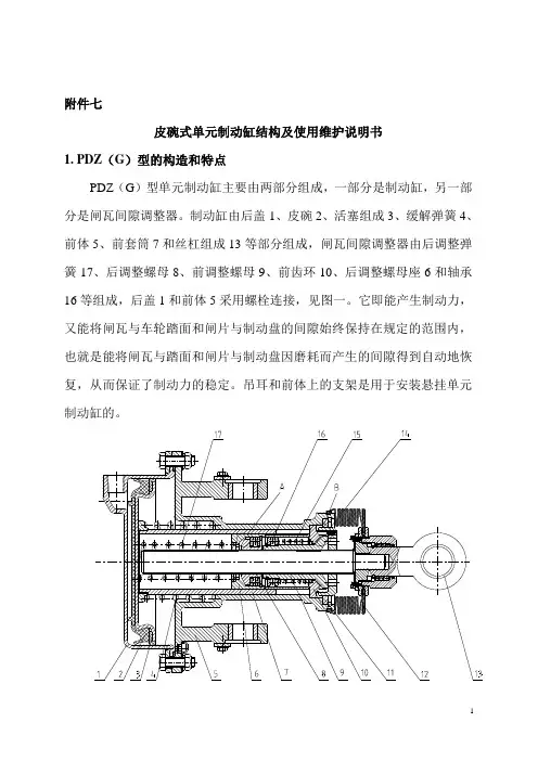
附件七皮碗式单元制动缸结构及使用维护说明书1. PDZ(G)型的构造和特点PDZ(G)型单元制动缸主要由两部分组成,一部分是制动缸,另一部分是闸瓦间隙调整器。
制动缸由后盖1、皮碗2、活塞组成3、缓解弹簧4、前体5、前套筒7和丝杠组成13等部分组成,闸瓦间隙调整器由后调整弹簧17、后调整螺母8、前调整螺母9、前齿环10、后调整螺母座6和轴承16等组成,后盖1和前体5采用螺栓连接,见图一。
它即能产生制动力,又能将闸瓦与车轮踏面和闸片与制动盘的间隙始终保持在规定的范围内,也就是能将闸瓦与踏面和闸片与制动盘因磨耗而产生的间隙得到自动地恢复,从而保证了制动力的稳定。
吊耳和前体上的支架是用于安装悬挂单元制动缸的。
图1 PDZ(G)型单元制动缸的结构1-后盖2-皮碗3-活塞组成4-缓解弹簧5-前体6-后调整螺母座7-前套筒8-后调整螺母9-前调整螺母10-前齿环11-止环12-防尘套13-丝杠组成14-前挡圈15-前调整弹簧16-轴承17-后调整弹簧1.1该制动缸采用单向作用式,即闸瓦或闸片磨耗后可自动调整过大的闸瓦或闸片间隙,当间隙过小时(更换新闸瓦),需要人工转动复原螺母来调整;1.2该制动缸系列采用皮碗活塞式结构,皮碗采用特殊结构的自封式整体橡胶皮碗,当皮碗磨耗后,仍能保持原有的过盈量,使密封性能不受影响,并且皮碗的受力硬芯较大,导向由尼龙支撑环导向,整个皮碗的受力变形部分很小,因而不会出现褶裂,橡胶皮碗只起密封作用。
该结构检修方便,不需任何工具就可以更换,更换后不需重新压紧。
1.3考虑到单元制动缸在转向架上的恶劣工作环境,后盖采用不锈钢精铸而后机加工成型,内表面采用抛光工艺,减小了摩擦阻力,避免了在运用过程中的锈蚀;1.4丝杠采用四头不自锁螺纹,前后调整螺母在丝杠上转动灵活,锁闭以锥面方式锁闭,性能可靠。
2. PDZ(G)型单元制动缸的作用原理PDZ(G)型单元制动缸的工作状态可分为:正常间隙制动位、正常间隙缓解位、过大间隙制动位和过大间隙缓解位等四部分组成。
工作原理该系列液压推杆制动器由制动架和相匹配的yt1型电力液压推动器两大部分组成。
当通电时,电力液压推动器动作,其推杆迅速升起,并通过杠杆作用把制动瓦打开(松闸);当断电时,电力液压推动器的推杆在弹簧力的作用下,迅速下降,并通过杠杆作用把制动瓦合拢(抱闸)。
□制动器的安装及调整●制动器安装方式:○纵装:松开螺母4、5使主弹簧处于自由状态,松开6、8螺母,转动螺杆7撑开制动臂,再将制动器套装在制动轮节器9—弹簧座spring base 上。
10—弹簧架刻度机 spring notches ○横装:当制动轮已装在电机与其它机件之间时,松开螺母4、5、6、7、8,转动螺杆取下螺杆3和7,将制动臂放倒。
从侧南装到制动轮上。
●制动器的调整○推动器工作行程的调整在保证闸瓦最小退距的情况下,推动器的工作行程愈小愈理想,因此需要调节其安装高度h1,其调整方法:松开螺母6和8(见图),转动螺杆7,使h1安装尺寸符合表1的要求。
调好后拧紧螺母6、8。
○制动力矩的调整松开螺母4,夹住螺杆的尾部方头,转动螺母5,使方形弹簧座位于弹簧架刻线以内,调整发后将螺母4和5拧紧退即可。
○制动瓦的退距调整当制动瓦打开时,调整螺栓1,使两边退距基本保持一致。
○固定制动瓦的螺母(见图),应松紧适当,使制动瓦与制动轮可以随位。
□使用和维修要定期检查制动器的工作状况。
检查时应着重以下各项:○制动器的构件无能运动是否正常,调整螺母是否紧固。
○推动器的构件是否正常,液压油是否足量。
有无漏油和渗油现象。
引入电线的绝缘是否良好。
○尺寸h1不得小于表1所列之最小尺寸,如超出要求须立即调整,否则失去制动作用。
○制动瓦是否正常的靠在制动轮上,磨擦表面的状态是否完好,有无油腻脏物。
当制动衬垫的厚度达到表2中的数值时,则应更换制动衬垫。
○制动轮的温度不应超过200℃。
○杠杆和弹簧发现裂纹应更换。
篇二:制动器说明书(参考) 1 绪论1.1 课题背景及目的汽车的普及伴随着能源消耗的增多,而如今的生活,汽车已经是人们日常生活离不开的必要工具。
制动单元DBU-1030/4045/4200用户手册1.综述DBU系列制动单元的作用是将马达在减速的过程中产生的再生能量,以热能的形式消耗在制动电阻上,从而改善变频器的制动性能及缩短变频器的制动时间。
在使用DBU系列制动单元之前,请仔细阅读本说明,如有疑问,请与我公司联系。
本说明对你的日常维护,维修;故障检测,检修提供了有力的帮助。
1.1购入检查所有制动单元在出厂前,均经过严格仔细的检验,测试;在你开箱验收时,请确认如下事项.如有异常,请与我公司业务部联系.。
检查项目检查方法与订购的产品是否一致? 查看CDBR的型号.所收物品是否有损伤? 查看整体外观,检查制动单元是否在运输中损伤1.2 制动单元型号说明1.3 DBU 系列制动单元技术条件ED :表示制动率在一个制动周期为120sS 时,制动时间所占比率.如下图可表示为ED=t1/t2=10%.t表1.41为ED=10%时的配置表,普通机械、10层一下电梯、起重机大小车选用。
AC200V~AC300V AC380V~AC460V 制动单元型号-DBU 2015 2022 2030 4030 4045 4220 4300 峰值电流(A) 50 75 90 50 75 300 500 额定电流(A) 15 25 30 15 25 85120配线 mm 24-64-66-84-64-616-36 25-50制动起始电压(V) 380V ±5VDC630/DC660/DC690/DC730/DC760V ±10V 最大回滞误差 约8V约16V 输入输出特性同步信号可多台并机,推鉴不超过3台。
电源 直流母线电压DC 243-400V DC 460~800V散热器过热 温度开关+85℃保护故障输出 RELAY 接点0.6A125V AC/2A30VDC(Ta,Tb,Tc) 外接电源R,S 端子4220、4300两款需外接380V AC 电源于R,S 端子,有外接电源时,红色POWER 指示灯亮散热风机工作条件 制动单元,能量吸收电阻板温升超过+45℃时风机工作,低于+45℃风机停止工作电源指示PCB 上直流母线输入端子有电压(大于50V )输入,红色上电“POWER ”指示灯亮指示功能运行指示制动单元工作时,绿色“BRAKING ”指示灯亮 环境温度 -10℃~+40℃(无冰冻) 存储温度 -10℃~+50℃ 湿度 90%RH(无凝霜)环境条件振动10~20HZ 为1G, 20~50HZ 可达0.2G 机械构造壁挂式IP20变频器功率KW 制动单元型号 制动单 元 数 量 电阻配置 电阻数量 制动转矩 (10%ED) 0.4 DBU-4015 1 70W 750Ω 1230 0.75 DBU-4015 1 70W 750Ω 1 130 1.5 DBU-4015 1 260W 400Ω 1 125 2.2 DBU-4015 1 260W 250Ω 1 135 3.7 DBU-4015 1 390W 150Ω 1 135 5.5 DBU-4015 1 520W 100Ω 1 135 7.5 DBU-4015 1 780W 75Ω 1 130 11 DBU-4015 1 1040W 50Ω 1 135 15 DBU-4015 1 1560W 40Ω 1 125 18.5 DBU-4030 1 4800W 32Ω 1 125 22 DBU-4030 1 4800W 27.2Ω 1 125 30 DBU-4030 1 6000W 20Ω 1 125 37 DBU-4045 1 9600W 16Ω 1 125 45 DBU -4045 1 9600W 13.6Ω 1 125 55 DBU -4030 2 6000W 20Ω 2 135 75 DBU -4045 2 9600W 13.6Ω 2 145 110 DBU -4030 3 9600W 20Ω 3 100 160 DBU -4220 1 40KW 3.4Ω 1 140 220 DBU -4220 1 60KW 3.2Ω 1 110 300 DBU -4220 2 40KW4.5Ω 2 110 600DBU -4220360KW3Ω3130ED : 表示制动率在一个制动周期为120s 时,制动时间所占比率,如下图可表示为ED=t1/t2=20%.。
港迪变频器HF500系列快速使用指南2016.10.13武汉港迪电气传动技术有限公司Wuhan Guide Electric Drive Technology Co.,Ltd.目录一、 上电前 (1)二、 快速启动设置 (2)三、 端子控制运行 (4)四、 模拟量控制运行: (5)五、 电机自学习 (7)六、 Profibus通讯控制运行 (9)七、 保护参数 (13)八、 制动器控制 (14)九、 并机变频器调试 (16)十、 特殊功能 (17)1、 电机选择 (17)2、 力矩控制与速度控制切换(矢量控制模式下) (18)3、 力矩控制,速度限制(矢量控制模式下) (19)4、 力矩限制(矢量控制模式下) (19)5、 主从力矩控制(矢量控制模式下) (19)6、 自动恒功率控制(需在现场验证) (矢量控制模式下) (23)7、 上电自动运行功能 (25)8、 旋转机构自由滑行停车 (25)9、 运行过程中修改加减速时间(V1.12以上版本中有,V1.05版本中无) (26)10、 自由功能块 (26)十一、 新增(V1.12) (28)1、 监视值 (28)2、 晶闸管动作选项 (28)3、 驱动多台电机 (28)4、 大车机构开闸参数 (28)5、 龙门吊防止振动 (28)6、 主从机构转动惯量自学习 (29)7、 异常速度错误 (29)十二、 新增(V1.13) (29)1、 DROOP功能(双机刚性联轴/速度控制‐‐‐‐推荐) (29)2、 主从方法2功能(双机刚性联轴/速度控制) (30)3、 同步功能(双机非刚性联轴) (31)4、 开环矢量速度估算滤波时间 (36)5、 速度控制/零转矩切换功能 (36)十三、 新增(V1.16) (37)1、 新增一种减速过压抑制功能 (37)2、 新增DI端子功能“开抱闸接触器反馈确认” (37)3、 新增抓斗防开斗功能 (38)4、 电机超频 (38)5、 模拟常规切电阻控制 (39)一、 上电前Step 1.检查主回路端子是否接紧,有无松动现象,抽查控制线是否有松动现象。