超声波电源机箱产品说明书
- 格式:docx
- 大小:291.38 KB
- 文档页数:10
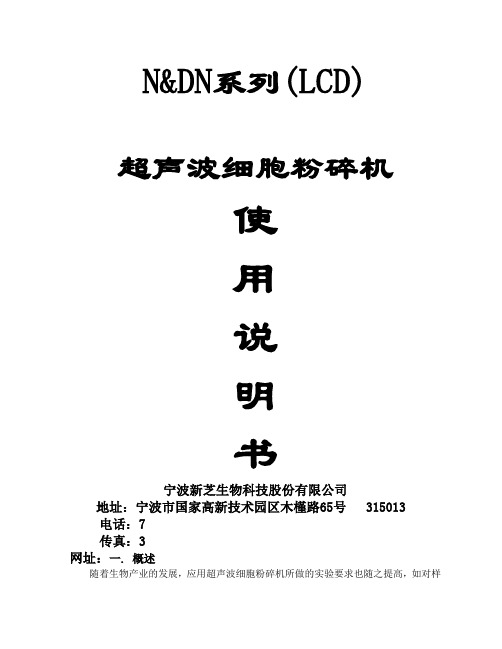
N&DN系列(LCD)超声波细胞粉碎机使用说明书宁波新芝生物科技股份有限公司地址:宁波市国家高新技术园区木槿路65号 315013电话:7传真:3网址:一. 概述随着生物产业的发展,应用超声波细胞粉碎机所做的实验要求也随之提高,如对样品温度的测定、控制,低温冷却样品及整机的智能化程度的提高等等,都提出了新的要求,为进一步完善此类仪器的各项性能,我公司在现有各种型号的超声波细胞粉碎机的基础上,吸收国外最新技术,结合微电脑控制、选频、测温、保护等软硬件技术而研制的超声波细胞粉碎机,它具有技术先进、性能可靠、操作简便、外型美观、显示清晰明亮、测温控温精确等优点。
超声波细胞粉碎机是一种利用强超声在液体中产生空化效应,对物质进行超声处理的多功能、多用途的仪器,能用于动植物组织、细胞、细菌、芽胞菌种的破碎,同时可用来乳化、分离、分散、匀化、提取、脱气、清洗及加速化学反应等等。
该机广泛应用于生物化学、微生物学、药物化学、表面化学、物理学、动物学、农学、医学、制药等领域教学、科研、生产。
Ф12 1/2”20-25KHz 100-950W 100 - 200mlФ15 5/8”20-25KHz- 500mlФ18 3/4”20-25KHz 200-950W 200 - 500mlФ20 3/4” -1000mlФ25 1” -1200ml本机由超声波发生器和超声波换能器组件两大部分组成。
超声波发生器(电源)是将220VAC、50Hz的单相电通过变频器件变为20-25kHz、约600V的交变电能、并以适当的阻抗与功率匹配来推动换能器,作纵向机械振动,振动波通过浸入在样品溶液中的钛合金变幅杆对被破碎的各类细胞产生空化效应,从而达到破碎细胞之目的。
其电原理由整流电源,开关电源、变频系统、功率放大器、锁相频率自动跟踪器、功率调节器、功率检测器、功率保护器及微电脑控制等组成。
换能器组件是由压电振子、变幅放大器所组成的产生机械能的聚能变幅装置。

UltrasoundAuto Registration in less than one minuteThe Philips EPIQ ultrasound system features our most powerful Philips architecture ever applied to ultrasound imaging – touching all aspects of acoustic acquisition and processing, allowing ultrasound to evolve to a more definitive modality. Anatomical Intelligence Ultrasound (AIUS) allows EPIQ Fusion and Navigation Auto Registration to provide successfulalignment of CT volumes to ultrasound in under one minute for the effective characterization of lesions. Performing automated fusion in less than one minute allows for more time to focus on the procedure ahead and less time on performing the registration necessary for accurate fusion.Fusion combines the strengths of multiple modalitiesUltrasound is a fast, high-resolution, and dynamictool but can often lack the anatomical context provided by CT and MRI. Fusion allows specific regions of interest to be targeted for highly detailed analysis while benefiting from the anatomical detail provided by CT or MRI. This can be ideal for contrast-enhanced ultrasound (CEUS) examinations of indeterminate abdominallesions, especially if there are multiple lesions that require interrogation, or if a lesion is unidentifiable on standard B-mode ultrasound.Fusion imaging benefits are based on the ability to bring together innate advantages of various imaging modalities that helps to provide the best possible outcome for the patient, but registration of two imaging modalities can be time-consuming and technically challenging, often taking up to 10 minutes to achieve successful fusion with conventional registration techniques. Now with Evolution 1.0 the EPIQ platform has fully integrated fusion and navigation capabilities that helps clinicians achieve fast fusion of different modalities and high levels of clinical confidence .Auto Registration on EPIQ Evolution 1.0A 1.5 cm recurrent hepatocellular carcinoma in the left lobe of the liver in a 79-year-old patient with a history of liver cirrhosis was examined under ultrasound using Auto Registration. This occult mass demonstrated well under contrast enhanced CT, but was previously undetected under ultrasound. Upon re-examination, this time using the Philips EPIQ ultrasound system, the occult mass was seen as a hypervascular region relative to the surrounding parenchyma with contrast ultrasound.A previously acquired CT scan was imported into the Philips EPIQ system for fusion with contrast-enhanced ultrasound. The patient was positioned supine with the Philips patient tracker on the xiphisternum to maintain fusion accuracy despite patient motion throughout the procedure.Traditional fusion techniques would have required the use of at least one internal landmark such as a vessel confluence as an anchor point for the fusion between the two modalities. Due to advanced cirrhosis, much of the portal tree in the liver had become very narrow and was poorly visualized in ultrasound. The lack of identifiable anatomy on ultrasound made traditional fusion methods impossible.Prof. Imai performed Auto Registration between a priorcontrast CT and ultrasound using the vessel-based technique. An ultrasound sweep volume was acquired to include optimal display of the portal vasculature.The Auto Registration tool performed segmentation of vessels from the hepatic cell phase (although portal venous phase is also commonly used by other centers) image series from the CT scan, as well as the portal vessels that were included in the ultrasound volume acquisition. Despite a narrowing of the portal vasculature in this patient, Prof. Imai succeeded in assuring adequate vessels in this ultrasound volume.Alignment of vessel maps took less than one minute to provide a clear demonstration of the mass on CT/ultrasound fusion.Correct alignment between the CT and ultrasound was validated by scanning in multiple planes over the liver and by reviewing the corresponding fused image.Of note: when Prof. Imai can visualize sufficient vessels on the ultrasound image – as in this case – he performs vessel-based registration. In cases where visualization of vessels present a challenge, Prof. Imai starts with surface-based registration and focuses the sweep volume on the posterior surface of the liver.Once the images are fused, Prof. Imai typically checks from both the left and right lobes, consistently finding Auto Registration to be accurate. Prof. Imai states, “There are significant advantagesProf. Yasuharu Imai, MD, FACP, FACGDirector, Department of Gastroenterology and Hepatology Tokyo Medical University Hachioji Medical Center Tokyo, JapanAuto Registration case study 1Two methods for Auto Registration in the liverRegistration using the liver surfaceAutomatic CT/ultrasound liver surface registration first extracts the 3D surface of the liver from the non-contrast CT scan. Then an ultrasound sweep of the liver is acquired such that part of the diaphragm touching the liver surface is captured in the sweep. The 3D shape of the diaphragm is automatically extracted from the ultrasound sweep. This 3D contour from the ultrasound can be considered as the partial 3D surface of the liver because they are adjacent to each other. The registration algorithm then finds the best way to align the 3D liver surface from the CT volume with the partial 3D liver surface from the ultrasound sweep volume. This is analogous to facial recognition, where one is trying to match a full picture with a portion of another picture of the same individual using thecontour of the face.Registration using the liver vesselsAutomatic CT/ultrasound liver vessel registration first extracts the 3D vessel trees of the entire liver from the contrast CT. Then an ultrasound sweep of the liver is acquired such that some vessels are captured in the sweep and automatically extracted. The registration algorithm then finds the best fit to align the 3D vessel trees within the liver CT volume and the 3D vessel trees acquired within the ultrasound sweep volume. This is analogous to matching fingerprints, where one is trying to match a complete fingerprint to a portion of another fingerprint of the same individual.To meet the demands of different clinical scenarios, Philips Auto Registration on EPIQEvolution 1.0 uses either vessel-based or surface-based techniques to perform automated fusion in less than one minute.2to using other modalities with ultrasound. Lesion detection issimplified for further evaluation, and an opportunity exists for subsequent monitoring. The added clinical benefit of fusion imaging does not have to add additional time to the procedure.”Follow-up careIn the case of this patient in which traditional approacheswere not feasible, Auto Registration allowed the team to localize the lesion and further characterize it using CEUS with the goal to continue monitoring this lesion using ultrasound with CEUS.Case 1. Contrast enhanced CT demonstrates lipiodol deposition after chemoembolization.Deposition of LipiodolRecurrent lesionCase 1. Fusion imaging assists in lesion localization underultrasound, where clearly defined on contrast CT. The recurrent lesion was unclear on B-mode ultrasound.Case 1. Sonazoid distribution on ultrasound fused with contrast enhanced CT for an anatomical reference.Fusion imaging of CT and CEUS demonstrates HCC RFA post-treatment in reference to the CT of the pre-treated area, confirming successful treatment.3Dr. MAF McNeill, MBBS FRCRDr. Ben Stenberg, PhDRadiology Department, Freeman Hospital NHS Newcastle upon Tyne, UKAuto Registration case study 2A 77-year-old patient with a history of previous Hartmann’s procedure for pT3 N1 Dukes C adenocarcinoma of the distal sigmoid colon had a routine follow-up CT at one year which demonstrated no evidence of disease recurrence. However,a repeat CT six months later performed for increasing weight loss demonstrated a small nodule adjacent to the rectalstump and a new 1.5 cm segment 5 liver lesion in keepingwith solitary metastasisThe patient’s past medical history includes cardiovascular disease, previous ischemic stroke, and severe chronic renal impairment. In combination with marked spinal degenerative disease, the patient is wheelchair-bound and has mobility only with assistance. As a result he was unable to tolerate MRI for further evaluation of the surgical resection site, and the decision was that treatment of the solitary liver metastasis with liver resection carried too great a risk given these co-morbidities.With surgery ruled out, percutaneous ablation of the liver metastasis was considered the best treatment option.The radiology team felt that microwave ablation was technically feasible, using ultrasound guidance as the preferred imaging modality due to pre-existing renal disease, with an effort to avoid additional iodinated contrast injections that would be required with CT guidance.An initial ultrasound was performed at pre-assessment,but the lesion could not be identified. The patient was promptly referred for fusion-guided CEUS to further localize the lesion andassess suitability for ultrasound-guided percutaneous access.A fused ultrasound and CT image confirms that the metastasis is truly invisible onB mode imaging, based on diagnosis; hence the need for contrast ultrasound assessment under fusion guidance.This patient exhibited some discomfort while being positioned on the bed, and was unable to lie supine for an extended period due to discomfort in his lower back. Furthermore, he was unable to lie flat due to neck discomfort, and deliberate efforts were made to keep the scanning time minimal.Fusion imaging using Auto Registration was performed usingthe C9-2 transducer under the general abdominal setting.A manual sweep of the liver was acquired, with the focus onthe liver surface. The diaphragmatic surface from the sweep acquisition was automatically aligned to that on the pre-acquired CT volume. Image fusion was achieved in less than a minute.Fusion of the CT and ultrasound volumes provided the clinician with an immediate multi-planar reconstruction of the CT volume, offering a dynamic CT display that aligned to the real-time ultrasound image. Dr. McNeill scanned to locate the lesion on the reformatted CT display, to assist in finding the area to focus on the real-time ultrasound image for further evaluation with contrast.45Progressive peripheral washout confirms the malignant nature of the lesion.Subtle central vascularity seen in a predominantly hypo-enhancinglesion, appreciated on the initial arterial phase.A single bolus of 2.4 ml ultrasound contrast agent was injected via a peripheral cannula. The lesion demonstrated initial hypo-enhancement in the arterial phase, with peripheral wash out through the portal venous and late phase. This confirmed the lesion to be metastatic in nature, and as suspectedon CT, appropriately sited for percutaneous access, and deep enough to the liver capsule to allow for microwave ablation.Dr. McNeill states, “Fusion imaging with Philips Auto Registration proved to be clinically relevant without shifting focus and time away from the patient’s needs. The clinical value of fusion in this case is self-evident, as it eliminated the need for additional iodinated contrast as used in CT, as well as offering a viable alternative for treatment planning.”Follow-up careThe general preference at this facility is to perform procedures under ultrasound guidance where possible. Furthermore,ultrasound-guided treatment is ideal for this patient because the iodinated contrast used in CT increases the chance of contrast-induced nephropathy in an already high-riskpatient with chronic kidney disease. Percutaneous microwave ablation will be performed under general anaesthetic using fusion-guided CEUS to guide needle placement. Dr. McNeill states, “Percutaneous treatment is possible in this patient as fusion-guided CEUS allows a lesion not visible on B-mode ultrasound to be confidently targeted for microwave ablation. Co-morbidities make CT guided ablation or surgical resection unsuitable. Therefore with limited treatment options we are able to offer a potentially curative procedure rather than other higher-risk procedures, or possibly palliation/best supportive care.”6Auto Registration using a vessel based segmentation of theportal vasculature.Auto Registration using a vessel based segmentation of theportal vasculature.Fusion imaging – surface based Auto Registration. Visible target areas on CT and ultrasound confirm accurate alignment.Auto Registration using a vessel based segmentation of theportal vasculature.The Freeman Hospital clinicians offer tips for making the mostof fusion imaging, based on their own experiences.While there are several methods of fusion registration, including point matching and plane matching, they have found Auto Registration to be quick and easy because it allows accurate registration with a simple sweep through the liver. The data auto-aligns with precision, without the need to perform additional fine manual adjustments. Fusion is performed in three planes, rather than in two dimensions (as with plane matching), which reduces error margins and makes registration more robust, particularly within the liver and kidneys. As might be expected, small error margins are unavoidable due to factors such as differing patient incline, position, and respiration, compounded by distance. They would routinely use Auto Registration for a study of the liver or kidneys, and reserve plane matching for examinations of EVAR grafts, which lends itself nicely to plane matching given the static graft material being readily identified on both CT and ultrasound.Auto Registration typically reduces the registration processto less than one minute. A difficult point match registrationcan take between seven to ten minutes to adequately perform.Clinical tips1. There are several steps that can be taken to increase thechances of success with Auto Registration. Because the Auto Registration function works by detecting and matching specific anatomical landmarks (for example, vessels or diaphragm),it only works if those structures are available on the 3Dultrasound sweep acquired during the registration process.Therefore a high-quality image is important, and a goodacoustic window to access the liver is key, preferably atpaused, neutral respiration. This is likely to be an intercostal view of the liver hilum for a vascular match, and a subcostalor intercostal view with as much diaphragm visible as possible for the surface match. The greater the volume and the better optimized the image, the greater the success rates.2. It is also important to realize that the success of AutoRegistration is patient-dependent, in much the same waya standard B-mode ultrasound is affected by patient factors.A patient who is unable to breath-hold or cooperate for areasonable period of time may significantly reduce the chance of successful Auto Registration.3. Quality of the cross-sectional study to be fused should alsobe high, as imaging degraded by artifacts will make the process more challenging. Similarly, if there has been a significantchange in the internal abdominopelvic structures, fusion may not be possible (for example, reduction or increase in volume of ascites).4. Ultrasound fusion is a dynamic study performed with patientswho are moving and breathing, which means that motiondiscrepancies occur between the two fused images at various phases during the respiratory cycle. As long as the practitioner is aware of this, it does not greatly affect contrast studieswhere a close fusion (<10 mm discrepancy) is sufficient.The team initially spent time attempting to achieve perfectfusion, before realizing that this was unnecessary in the majority of cases because close fusion was sufficient to provide them with the clinical benefits of the examination.5. Of course, great importance should be given to more accuratefusion during interventional procedures, and initial care should be taken to register the ultrasound and cross-sectional dataset at the point of respiration at which the procedure is likely to be performed, allowing the greatest accuracy of registration at the required point.Keys to finding successwith Auto Registration7©2016 Koninklijke Philips N.V. All rights are reserved.Philips reserves the right to make changes in specifications and/or to discontinue any product at any time without notice or obligation and will not be liable for any consequences resulting from the use of this Printed in The Netherlands. 4522 991 19381 * MAY 2016Applications for fusion imaging at Freeman Hospital, Newcastle upon Tyne Additional benefits of thePhilips approach to fusionPhilips fusion imaging has the capability of free handAuto Registration with C5-1, C9-2, S5-1, and electronicAuto Registration with X6-1 to provide clinicians accessto quick and easy fusion.The Philips system features a separate patient tracker, which allows the magnetic field generator to be moved during an examination without having to reset the whole procedure or perform a new registration process. In the view of Dr. McNeill “This is particularly useful in the theatre setting in our practice where the registration is performed before the patient is prepped and the field generator can be moved and reinstated during the sterilization process without interfering with the accuracy of the registration.There are other instances where this is useful, such as movingthe field generator for access for cannulation during a contrast study, or during percutaneous biopsies where the field generator may not be optimally positioned having started the procedure.The other standout feature with the Philips system is the depthof functionality. Not only are there multiple ways to register, adjust, and display the fusion imaging, but there are multiple applications such as ultrasound-ultrasound fusion, multiple target planning, and needle tracking functions. This allows the system to grow with the needs of your service instead of limiting it.”Endovascular aneurysm repair (EVAR) graft assessment Microbubble studies of EVAR grafts have been dramatically improved with the addition of fusion technology, allowing clinicians to combine the high sensitivity of CEUS withthe anatomical data provided by CT for greater overall detection and evaluation of endoleaks, where CT findingsare often equivocal.Percutaneous ablation of liver lesionsThe team is now able to treat lesions in the liver that are difficult to identify and target with any single imaging modality. Fusion-guided CEUS provides far greater confidence in the ability to perform percutaneous therapy, and allows for treatment that may otherwise not be possible. They feel this impact is one of the greatest strengths of the system for them.Focal liver biopsiesTargeting active tumors, particularly in previously ablatedliver lesions, is becoming increasingly important in the context of developing percutaneous treatment of primary or secondary liver tumors. Lesions that develop recurrence often have active tumor in their periphery. This can be difficult to appreciateon B-mode ultrasound, and may be subtle or indeterminate on CT. Combining CEUS with CT allows accurate definitionof potential sites of recurrence and enables accurate targeting for tissue sampling.Head and neck applicationsTargeting lesions and PET hotspots in the head and neck using linear transducer fusion is a direction the clinicians at Freeman Hospital would like to explore in the future as this has the potential to be of great benefit, ensuring PET-positive nodules or nodes are targeted for biopsy and not adjacent reactive lymphadenopathy.。

超声波使用说明书模块实物图如下图所示:123(12V+)(GND)(485通信口)一、接线说明模块采用DC12V供电;图中标号为1的红色箭头处接电源正,标号为2的红色箭头处接电源负。
标号为3的红色箭头处接485通信线。
二、通信协议说明模块采用485通信,波特率为9600;通信协议如下:协议头预留字节预留字节预留字节距离高字节距离低字节帧尾校验和0Xfe0X000X000X000Xxx0Xxx0Xef0Xxx校验和计算方法:从协议头到帧尾个各数据之和取最低两位距离返回值单位为:mm;例:0xfe0x000x000x000x040xb00xef0xa1当返回数据如上所示时,测距结果为1200mm。
三、模块测量方法由于模块是高精度设计用,所以对测量环境有严格的说明界定。
请参考如下测量安装方式,否则会产生较大的测量误差。
安装方式如下:滤波处理装置,可以用PCB板来固定代替移动平面是本模块的移动方向,反射平面是基础高度。
在移动平面方向前后运动将会测量到实际的反射平面与模块的实际距离。
测量条件:1:参考平面(模块固定的平面)一定要垂直于反射平面。
2:测量模块在反射面这个方向上的1米半径范围内不能有遮挡物。
3:在移动模块到了指定位置后(想测量的距离位置处),模块的前端一定要绝对垂直于反射面。
4:根据超声波的扇形反射面原理,最好在超声波的接收端安装反射能量限定装置,这样能更准确的获得实际的测量结果。
在实际应用场合,有更多的安装要求。
基本的测量测试,照目前条件能基本反应出来。
成都镓舒适科技有限公司2014-09-01。

目录一、仪器介绍...............................................................................................- 2 -1、HS Q6性能特点..............................................................................- 2 -2、HS Q6 技术参数:.........................................................................- 3 -二、仪器的按键说明 ...................................................................................- 4 -三、仪器各功能介绍...................................................................................- 5 -1、全屏 .........................................................................................- 5 -2、参数设置 .........................................................................................- 6 -3、调校 .........................................................................................- 6 -4、曲线制作 .........................................................................................- 7 -5、包络 .........................................................................................- 8 -6、工艺保存 .........................................................................................- 8 -7、焊缝功能 .........................................................................................- 9 -9、性能校验 ...................................................................................... - 10 -10、频谱分析 .................................................................................... - 11 -11、厚度测量 .................................................................................... - 11 -12、缺陷Φ值 .................................................................................... - 11 -四、文件管理............................................................................................ - 12 -五、工艺文件............................................................................................ - 12 -六、Q6外部接口使用说明 ...................................................................... - 14 -七、仪器的安全使用、保养与维护 .........................................................- 17 -HS Q6 微型台式超声波检测仪全程、连续、动态、大容量实时记录检测回波、数据超声仪器的又一创意、创新高端产品,性能更优一、仪器介绍1、HS Q6性能特点→4.8寸彩色宽屏,分辨率高达800×480,亮度400cd,亦可全屏显示,不同环境,不同要求,共同满足→独具一键摇杆技术,检测一指操控,舍我其谁→SD卡储存设计,有限空间,无限储存,完全满足动态波形全过程记录→超声检测、超声测厚,源自一体,容于一机→高性能安全环保锂电池,模块插接式,使用便捷、工作高效→功能全面,性能卓越,裂纹测高,AVG曲线,缺陷φ值自动计算,焊缝坡口形式,性能校验,曲面修正等功能→高速FFT处理,进行频谱分析,实测探头频率→VGA接口,无缝对接投影仪→主/从USB接口,传输方便→通过U盘直接升级软件→近场高分辨力专门针对薄板和复合材料的探伤应用,对金属类材料和焊缝的探伤,性能更优本仪器的基本功能:全屏、调校、曲线制作(AVG/DAC)、缺陷φ值、厚度测量、包络、伤波存储、动态记录、自动增益、波峰记忆、灵敏度恢复、距离补偿、焊缝坡口图、频谱分析、裂纹测高、性能校验等。

DCX V系列超声波发生器使用手册EDP 500-220-112版本号:Rev.A必能信超声(上海)有限公司上海市松江区荣乐东路758号邮编:201613电话:+86-021-3781-0588DCX V系列超声波发生器使用手册手册更新必能信通过不断改进设备的电路及零部件来保证其在超声波塑料焊接、金属焊接、清洗和相关技术领域的领先地位。
当这些技术改进通过完整的测试程序之后即投入到实际生产中。
关于任何技术改进的信息都将会增加到新版本的技术文件中并打印成册。
因此,当用户就某一部件向售后服务进行咨询时,请告知文件首页上的版本信息及位于页脚处的打印日期。
版权和商标版权©2012必能信超声公司保留所有权利没有必能信超声公司的书面许可,本手册的内容不得以任何形式进行复制。
Mylar是杜邦帝人薄膜公司的注册商标。
Loctite 是乐泰公司的注册商标。
WD-40是WD-40制造公司的注册商标。
Windows 7, Windows Vista和Windows XP是微软公司的注册商标。
在此提到的其他商标和服务标志都有其相应的所有者。
DCX V系列超声波发生器使用手册前言非常感谢您选购必能信的产品!必能信DCX V系列焊接系统是利用超声波能量对塑料件进行焊接的设备,是此类先进技术的最新一代产品,适用于多种不同的应用要求。
本操作手册是该产品技术文件的一部分,请将手册和设备放置在一起,便于查询参考。
再次感谢您选择必能信!绪论操作手册分成若干个章节,便于用户查找设备搬运、安装、设置、编程、操作以及维护等信息。
用户可以通过目录快速查找到所需内容。
如果需要其他帮助或信息,请联系必能信生产支持部门(请参考1.4小节:如何联系必能信)或与当地必能信销售代表联系。
DCX V系列超声波发生器使用手册目录1安全与支持1.1安全要求及警告 - - - - - - - - - - - - - - - - - - - - - - - - - - - - - - - - - - 1-21.1.1手册中的常用标志 - - - - - - - - - - - - - - - - - - - - - - - - - - - - - - - 1-21.1.2产品上常用标志 - - - - - - - - - - - - - - - - - - - - - - - - - - - - - - - - 1-21.2预防措施- - - - - - - - - - - - - - - - - - - - - - - - - - - - - - - - - - - - - - 1-31.2.1设备用途- - - - - - - - - - - - - - - - - - - - - - - - - - - - - - - - - - - - 1-41.2.2排放物 - - - - - - - - - - - - - - - - - - - - - - - - - - - - - - - - - - - - - 1-41.2.3设置工作场所- - - - - - - - - - - - - - - - - - - - - - - - - - - - - - - - - - 1-41.2.4遵循的规章及条例 - - - - - - - - - - - - - - - - - - - - - - - - - - - - - - - 1-51.3保修政策- - - - - - - - - - - - - - - - - - - - - - - - - - - - - - - - - - - - - - 1-61.4如何联系必能信 - - - - - - - - - - - - - - - - - - - - - - - - - - - - - - - - - - 1-91.4.1联系必能信之前 - - - - - - - - - - - - - - - - - - - - - - - - - - - - - - - - 1-91.5设备返修- - - - - - - - - - - - - - - - - - - - - - - - - - - - - - - - - - - -1-102设备概述2.1产品型号- - - - - - - - - - - - - - - - - - - - - - - - - - - - - - - - - - - - - - 2-22.1.1设备简介- - - - - - - - - - - - - - - - - - - - - - - - - - - - - - - - - - - - 2-32.1.2超声波发生器使用手册 - - - - - - - - - - - - - - - - - - - - - - - - - - - - - 2-42.2关于其他必能信设备 - - - - - - - - - - - - - - - - - - - - - - - - - - - - - - - - 2-52.3与必能信产品的兼容 - - - - - - - - - - - - - - - - - - - - - - - - - - - - - - - - 2-52.4系统特性- - - - - - - - - - - - - - - - - - - - - - - - - - - - - - - - - - - - - - 2-62.4.1焊接系统- - - - - - - - - - - - - - - - - - - - - - - - - - - - - - - - - - - - 2-62.4.2超声波发生器- - - - - - - - - - - - - - - - - - - - - - - - - - - - - - - - - - 2-62.4.3机架 - - - - - - - - - - - - - - - - - - - - - - - - - - - - - - - - - - - - - - 2-62.4.4换能器/变幅器/焊头组件- - - - - - - - - - - - - - - - - - - - - - - - - - - 2-72.5控制器和显示器 - - - - - - - - - - - - - - - - - - - - - - - - - - - - - - - - - - 2-82.5.1DCX V系列超声波发生器前面板功能简介- - - - - - - - - - - - - - - - - - - - 2-82.5.2DCX V系列超声波发生器后面板功能简介- - - - - - - - - - - - - - - - - - - - 2-92.6焊接系统- - - - - - - - - - - - - - - - - - - - - - - - - - - - - - - - - - - - - -2-102.6.1工作原理- - - - - - - - - - - - - - - - - - - - - - - - - - - - - - - - - - - -2-102.6.2应用 - - - - - - - - - - - - - - - - - - - - - - - - - - - - - - - - - - - - - 2-102.7技术术语 - - - - - - - - - - - - - - - - - - - - - - - - - - - - - - - - - - - - - 2-103设备的运输及处理3.1设备运输 - - - - - - - - - - - - - - - - - - - - - - - - - - - - - - - - - - - - - - 3-23.1.1环境要求 - - - - - - - - - - - - - - - - - - - - - - - - - - - - - - - - - - - - 3-23.2设备接收 - - - - - - - - - - - - - - - - - - - - - - - - - - - - - - - - - - - - - - 3-23.3包装拆卸 - - - - - - - - - - - - - - - - - - - - - - - - - - - - - - - - - - - - - - 3-33.4小零件盘点 - - - - - - - - - - - - - - - - - - - - - - - - - - - - - - - - - - - - - 3-33.4.1电缆线 - - - - - - - - - - - - - - - - - - - - - - - - - - - - - - - - - - - - - 3-43.5设备发还 - - - - - - - - - - - - - - - - - - - - - - - - - - - - - - - - - - - - - - 3-44设备的安装及设置4.1关于安装 - - - - - - - - - - - - - - - - - - - - - - - - - - - - - - - - - - - - - - 4-24.2安装要求 - - - - - - - - - - - - - - - - - - - - - - - - - - - - - - - - - - - - - - 4-24.2.1安装空间 - - - - - - - - - - - - - - - - - - - - - - - - - - - - - - - - - - - - 4-24.2.2环境要求 - - - - - - - - - - - - - - - - - - - - - - - - - - - - - - - - - - - - 4-74.2.3电源输入范围- - - - - - - - - - - - - - - - - - - - - - - - - - - - - - - - - - 4-74.2.4气动要求 - - - - - - - - - - - - - - - - - - - - - - - - - - - - - - - - - - - - 4-74.3安装步骤 - - - - - - - - - - - - - - - - - - - - - - - - - - - - - - - - - - - - - - 4-84.3.1安装超声波发生器- - - - - - - - - - - - - - - - - - - - - - - - - - - - - - - - 4-84.3.2电气连接 - - - - - - - - - - - - - - - - - - - - - - - - - - - - - - - - - - - 4-104.4超声波发生器的设置 - - - - - - - - - - - - - - - - - - - - - - - - - - - - - - - 4-184.4.1选择报警模式- - - - - - - - - - - - - - - - - - - - - - - - - - - - - - - - - 4-184.4.2设置超声波发生器- - - - - - - - - - - - - - - - - - - - - - - - - - - - - - - 4-184.5换能器/变幅器/焊头组件的安装- - - - - - - - - - - - - - - - - - - - - - - - - 4-194.5.120kHz系统换能器/变幅器/焊头组件的安装 - - - - - - - - - - - - - - - - - 4-204.5.230kHz系统换能器/变幅器/焊头组件的安装 - - - - - - - - - - - - - - - - - 4-204.5.340kHz系统换能器/变幅器/焊头组件的安装 - - - - - - - - - - - - - - - - - 4-214.5.4焊头和焊嘴的组装- - - - - - - - - - - - - - - - - - - - - - - - - - - - - - - 4-214.6换能器冷却 - - - - - - - - - - - - - - - - - - - - - - - - - - - - - - - - - - - - 4-224.7安装调试 - - - - - - - - - - - - - - - - - - - - - - - - - - - - - - - - - - - - - 4-234.8需要帮助? - - - - - - - - - - - - - - - - - - - - - - - - - - - - - - - - - - - - 4-235技术参数5.1技术参数 - - - - - - - - - - - - - - - - - - - - - - - - - - - - - - - - - - - - - - 5-25.1.1环境要求 - - - - - - - - - - - - - - - - - - - - - - - - - - - - - - - - - - - - 5-25.1.2电气要求 - - - - - - - - - - - - - - - - - - - - - - - - - - - - - - - - - - - - 5-2DCX V系列超声波发生器使用手册5.2结构描述- - - - - - - - - - - - - - - - - - - - - - - - - - - - - - - - - - - - - - 5-45.3标准模块及元器件 - - - - - - - - - - - - - - - - - - - - - - - - - - - - - - - - - 5-55.3.1系统方框图- - - - - - - - - - - - - - - - - - - - - - - - - - - - - - - - - - - 5-55.3.2电路 - - - - - - - - - - - - - - - - - - - - - - - - - - - - - - - - - - - - - - 5-55.3.3换能器和变幅器 - - - - - - - - - - - - - - - - - - - - - - - - - - - - - - - - 5-75.3.4部件功能描述- - - - - - - - - - - - - - - - - - - - - - - - - - - - - - - - - -5-136设备的操作6.1启动超声能量- - - - - - - - - - - - - - - - - - - - - - - - - - - - - - - - - - - - 6-26.2振幅设置- - - - - - - - - - - - - - - - - - - - - - - - - - - - - - - - - - - - - - 6-26.2.1使用外部振幅控制 - - - - - - - - - - - - - - - - - - - - - - - - - - - - - - - 6-26.2.2使用网页界面- - - - - - - - - - - - - - - - - - - - - - - - - - - - - - - - - - 6-26.3重设超声波发生器报警 - - - - - - - - - - - - - - - - - - - - - - - - - - - - - - - 6-26.4网页界面- - - - - - - - - - - - - - - - - - - - - - - - - - - - - - - - - - - - - - 6-36.4.1系统要求- - - - - - - - - - - - - - - - - - - - - - - - - - - - - - - - - - - - 6-36.4.2连接至网页界面 - - - - - - - - - - - - - - - - - - - - - - - - - - - - - - - - 6-36.4.3网页界面的使用 - - - - - - - - - - - - - - - - - - - - - - - - - - - - - - - - 6-96.5超声测试- - - - - - - - - - - - - - - - - - - - - - - - - - - - - - - - - - - - - -6-106.5.1使用输入/输出接口 - - - - - - - - - - - - - - - - - - - - - - - - - - - - - -6-116.5.2使用网页界面- - - - - - - - - - - - - - - - - - - - - - - - - - - - - - - - - -6-117设备的维护7.1常规维护注意事项 - - - - - - - - - - - - - - - - - - - - - - - - - - - - - - - - - 7-27.2DCX V系列超声波发生器定期常规维护 - - - - - - - - - - - - - - - - - - - - - - - 7-37.2.1定期清洁设备- - - - - - - - - - - - - - - - - - - - - - - - - - - - - - - - - - 7-37.2.2换能器/变幅器/焊头组件的维护 - - - - - - - - - - - - - - - - - - - - - - - 7-47.2.3常规零件的更换 - - - - - - - - - - - - - - - - - - - - - - - - - - - - - - - - 7-77.3校准 - - - - - - - - - - - - - - - - - - - - - - - - - - - - - - - - - - - - - - - - 7-77.4元器件清单- - - - - - - - - - - - - - - - - - - - - - - - - - - - - - - - - - - - - 7-77.4.1系统电缆线清单 - - - - - - - - - - - - - - - - - - - - - - - - - - - - - - - - 7-87.4.2建议备件清单- - - - - - - - - - - - - - - - - - - - - - - - - - - - - - - - - - 7-87.5系统连线图- - - - - - - - - - - - - - - - - - - - - - - - - - - - - - - - - - - - -7-127.6故障分析- - - - - - - - - - - - - - - - - - - - - - - - - - - - - - - - - - - - - -7-137.6.1常见电气故障- - - - - - - - - - - - - - - - - - - - - - - - - - - - - - - - - -7-137.6.2风扇/电源开关故障 - - - - - - - - - - - - - - - - - - - - - - - - - - - - - -7-147.6.3超声功率故障- - - - - - - - - - - - - - - - - - - - - - - - - - - - - - - - - -7-147.6.4焊接循环故障- - - - - - - - - - - - - - - - - - - - - - - - - - - - - - - - - -7-157.7冷启动 - - - - - - - - - - - - - - - - - - - - - - - - - - - - - - - - - - - - - - -7-16 7.7.1执行一次冷启动操作 - - - - - - - - - - - - - - - - - - - - - - - - - - - - - -7-16DCX V系列超声波发生器使用手册附图索引图 1.1DCX V系列超声波发生器上的安全标志(水平安装式) - - - - - - - - - - - - - - - - - -1-2图 1.2DCX V系列超声波发生器上的安全标志(竖直安装式) - - - - - - - - - - - - - - - - - -1-3图 1.3CE标志- - - - - - - - - - - - - - - - - - - - - - - - - - - - - - - - - - - - - - - - -1-5图 2.1DCX V系列超声波发生器外形图(水平安装式) - - - - - - - - - - - - - - - - - - - - -2-3图 2.2DCX V系列超声波发生器外形图(竖直安装式) - - - - - - - - - - - - - - - - - - - - -2-3图 2.3DCX V系列超声波发生器前面板示意图 - - - - - - - - - - - - - - - - - - - - - - - - -2-8图 2.4DCX V系列超声波发生器后面板示意图 (水平安装式) - - - - - - - - - - - - - - - - - -2-9图 2.5DCX S系列超声波发生器后面板示意图 (竖直安装式) - - - - - - - - - - - - - - - - - -2-9图 4.1DCX V水平安装式超声波发生器外形图 - - - - - - - - - - - - - - - - - - - - - - - - -4-3图 4.2DCX V竖直安装式超声波发生器外形图(400 W, 750 W 和800 W) - - - - - - - - - - - -4-4图 4.3DCX V 竖直安装式超声波发生器外形图 (1.25 kW和1.5 kW) - - - - - - - - - - - - - - -4-5图 4.4DCX V竖直安装式超声波发生器外形图 (2.5 kW 和 4 kW) - - - - - - - - - - - - - - - -4-6图 4.5DCX V超声波发生器接口示意图 (水平安装式) - - - - - - - - - - - - - - - - - - - - 4-10图 4.6DCX V超声波发生器接口示意图 (竖直安装式) - - - - - - - - - - - - - - - - - - - - 4-10图 4.7用户输入/输出电缆识别和线色图解 - - - - - - - - - - - - - - - - - - - - - - - - - - 4-11图 4.8常见数字式输入/输出接线图 - - - - - - - - - - - - - - - - - - - - - - - - - - - - - 4-15图 4.9常见模拟式输入/输出接线图 - - - - - - - - - - - - - - - - - - - - - - - - - - - - - 4-15图 4.10射频电缆连接示意图- - - - - - - - - - - - - - - - - - - - - - - - - - - - - - - - - - 4-16图 4.11换能器/变幅器/焊头组装示意图 - - - - - - - - - - - - - - - - - - - - - - - - - - - 4-19图 4.12焊头和焊嘴组装示意图 - - - - - - - - - - - - - - - - - - - - - - - - - - - - - - - - 4-21图 5.1系统方框图 - - - - - - - - - - - - - - - - - - - - - - - - - - - - - - - - - - - - - - -5-5图 5.220 kHz CR-20S换能器外形图 - - - - - - - - - - - - - - - - - - - - - - - - - - - - - -5-7图 5.320 kHz CH-20S换能器外形图 - - - - - - - - - - - - - - - - - - - - - - - - - - - - - -5-8图 5.420 kHz变幅器外形图 - - - - - - - - - - - - - - - - - - - - - - - - - - - - - - - - - -5-8图 5.520 kHz换能器/变幅器/焊头组件外形图- - - - - - - - - - - - - - - - - - - - - - - - -5-9图 5.630 kHz换能器外形图 - - - - - - - - - - - - - - - - - - - - - - - - - - - - - - - - - 5-10图 5.730 kHz变幅器外形图 - - - - - - - - - - - - - - - - - - - - - - - - - - - - - - - - - 5-11图 5.830 kHz换能器/变幅器/焊头组件外形图- - - - - - - - - - - - - - - - - - - - - - - - 5-11图 5.940 kHz, 4TR和4TJ换能器外形图 - - - - - - - - - - - - - - - - - - - - - - - - - - - 5-12图 5.1040 kHz变幅器外形图 - - - - - - - - - - - - - - - - - - - - - - - - - - - - - - - - - 5-12图 5.1140 kHz换能器/变幅器/焊头组件外形图- - - - - - - - - - - - - - - - - - - - - - - - 5-13图 6.1测试连线图 - - - - - - - - - - - - - - - - - - - - - - - - - - - - - - - - - - - - - - 6-11图 7.1换能器/变幅器/焊头组件的接触面修整示意图 - - - - - - - - - - - - - - - - - - - - - 7-5图 7.2系统连线图 - - - - - - - - - - - - - - - - - - - - - - - - - - - - - - - - - - - - - -7-12DCX V系列超声波发生器使用手册附表索引表 1.1保修期- - - - - - - - - - - - - - - - - - - - - - - - - - - - - - - - - - - - - - - - - 1-6表 1.2联系电话- - - - - - - - - - - - - - - - - - - - - - - - - - - - - - - - - - - - - - - -1-11表 2.1产品型号- - - - - - - - - - - - - - - - - - - - - - - - - - - - - - - - - - - - - - - - 2-2表 2.2超声波发生器和换能器匹配表 - - - - - - - - - - - - - - - - - - - - - - - - - - - - - 2-5表 2.3DCX V系列超声波发生器前面板显示器- - - - - - - - - - - - - - - - - - - - - - - - - 2-8表 2.4DCX V系列超声波发生器后面板接口- - - - - - - - - - - - - - - - - - - - - - - - - - 2-9表 3.1环境要求一览表 - - - - - - - - - - - - - - - - - - - - - - - - - - - - - - - - - - - - 3-2表 3.2包装拆卸步骤 - - - - - - - - - - - - - - - - - - - - - - - - - - - - - - - - - - - - - 3-3表 3.3小零件盘点表 - - - - - - - - - - - - - - - - - - - - - - - - - - - - - - - - - - - - - 3-4表 3.4DCX V系列系统电缆线 - - - - - - - - - - - - - - - - - - - - - - - - - - - - - - - - 3-4表 4.1环境要求一览表 - - - - - - - - - - - - - - - - - - - - - - - - - - - - - - - - - - - - 4-7表 4.2输入电流和断路器规格- - - - - - - - - - - - - - - - - - - - - - - - - - - - - - - - - 4-7表 4.3用户输入/输出电缆线信号及信号规则 - - - - - - - - - - - - - - - - - - - - - - - - -4-11表 4.4数字输入信号的功能 - - - - - - - - - - - - - - - - - - - - - - - - - - - - - - - - - -4-12表 4.5数字输出信号的功能 - - - - - - - - - - - - - - - - - - - - - - - - - - - - - - - - - -4-13表 4.6模拟输入信号的功能 - - - - - - - - - - - - - - - - - - - - - - - - - - - - - - - - - -4-13表 4.7模拟输出信号的功能 - - - - - - - - - - - - - - - - - - - - - - - - - - - - - - - - - -4-13表 4.8默认用户输入/输出接口信号及信号规则 - - - - - - - - - - - - - - - - - - - - - - - -4-14表 4.9超声波组件扭矩值 - - - - - - - - - - - - - - - - - - - - - - - - - - - - - - - - - - -4-20表 4.10工具一览表 - - - - - - - - - - - - - - - - - - - - - - - - - - - - - - - - - - - - - -4-20表 4.11焊嘴扭矩值一览表 - - - - - - - - - - - - - - - - - - - - - - - - - - - - - - - - - - -4-21表 4.12连续运行最大功率 & 满功率占空比 - - - - - - - - - - - - - - - - - - - - - - - - - - -4-22表 4.13换能器冷却步骤 - - - - - - - - - - - - - - - - - - - - - - - - - - - - - - - - - - - -4-22表 5.1环境要求一览表 - - - - - - - - - - - - - - - - - - - - - - - - - - - - - - - - - - - - 5-2表 5.2输入电压- - - - - - - - - - - - - - - - - - - - - - - - - - - - - - - - - - - - - - - - 5-2表 5.3输入电流和断路器规格- - - - - - - - - - - - - - - - - - - - - - - - - - - - - - - - - 5-3表 5.4连续运行最大功率 - - - - - - - - - - - - - - - - - - - - - - - - - - - - - - - - - - - 5-3表 5.5DCX V系列超声波发生器尺寸一览表- - - - - - - - - - - - - - - - - - - - - - - - - - 5-4表 6.1重设DCX V超声波发生器 - - - - - - - - - - - - - - - - - - - - - - - - - - - - - - - 6-2表 6.2超声波发生器测试程序(用户输入/输出)- - - - - - - - - - - - - - - - - - - - - - - -6-11表 6.3超声波发生器测试程序(网页界面)- - - - - - - - - - - - - - - - - - - - - - - - - - -6-11表 7.1换能器/变幅器/焊头组件修整步骤- - - - - - - - - - - - - - - - - - - - - - - - - - - 7-4表 7.2超声波发生器组件扭矩值- - - - - - - - - - - - - - - - - - - - - - - - - - - - - - - - 7-6表 7.3螺栓扭矩值一览表 - - - - - - - - - - - - - - - - - - - - - - - - - - - - - - - - - - - 7-7表 7.4DCX V系列电缆线清单 - - - - - - - - - - - - - - - - - - - - - - - - - - - - - - - - 7-8表 7.5建议备件清单 - - - - - - - - - - - - - - - - - - - - - - - - - - - - - - - - - - - - - 7-8表 7.6DCX V系列超声波发生器使用的换能器- - - - - - - - - - - - - - - - - - - - - - - - - 7-9表 7.7DCX V系列超声波发生器使用的变幅器- - - - - - - - - - - - - - - - - - - - - - - - - 7-9表 7.8DCX V系列超声波发生器使用的其他零件 - - - - - - - - - - - - - - - - - - - - - - -7-10表 7.9常见电气故障的排除 - - - - - - - - - - - - - - - - - - - - - - - - - - - - - - - - - -7-13表 7.10风扇/电源开关故障的排除- - - - - - - - - - - - - - - - - - - - - - - - - - - - - - -7-14表 7.11超声波功率故障的排除- - - - - - - - - - - - - - - - - - - - - - - - - - - - - - - - -7-14表 7.12焊接循环故障的排除 - - - - - - - - - - - - - - - - - - - - - - - - - - - - - - - - - -7-15表 7.13冷启动步骤 - - - - - - - - - - - - - - - - - - - - - - - - - - - - - - - - - - - - - -7-16DCX V系列超声波发生器 1: 安全与支持使用手册1:安全与支持1.1安全要求及警告 - - - - - - - - - - - - - - - - - - - - - - - - - - - - - - - - - - 1-21.1.1手册中的常用标志 - - - - - - - - - - - - - - - - - - - - - - - - - - - - - - - 1-21.1.2产品上常用标志 - - - - - - - - - - - - - - - - - - - - - - - - - - - - - - - - 1-21.2预防措施- - - - - - - - - - - - - - - - - - - - - - - - - - - - - - - - - - - - - - 1-31.2.1设备用途- - - - - - - - - - - - - - - - - - - - - - - - - - - - - - - - - - - - 1-41.2.2排放物 - - - - - - - - - - - - - - - - - - - - - - - - - - - - - - - - - - - - - 1-41.2.3设置工作场所- - - - - - - - - - - - - - - - - - - - - - - - - - - - - - - - - - 1-41.2.4遵循的规章及条例 - - - - - - - - - - - - - - - - - - - - - - - - - - - - - - - 1-51.3保修政策- - - - - - - - - - - - - - - - - - - - - - - - - - - - - - - - - - - - - - 1-61.4如何联系必能信 - - - - - - - - - - - - - - - - - - - - - - - - - - - - - - - - - - 1-91.4.1联系必能信之前 - - - - - - - - - - - - - - - - - - - - - - - - - - - - - - - - 1-91.5设备返修- - - - - - - - - - - - - - - - - - - - - - - - - - - - - - - - - - - - - -1-10本章节主要介绍了操作手册中及产品上所使用的不同安全标志的含义,以及超声波焊接的其他安全信息,同时也提供了必能信的联系方式。

目录1、概述 (2)2、工作原理 (2)3、整机结构名称 (2)4、电气原理 (3)5、产品特点.......................................................................................................3-46、使用条件 (4)7、安装操作指南 (5)8、维护保养 (5)9、配套清单 (5)9、变幅杆更换...................................................................................................6-7上海生析超声仪器有限公司1、概述上海生析超声仪器有限公司是一家集研究、设计、生产、销售以及维修超声波设备的专业产家。
生析公司有着集十多年生产超声波设备经验,设计及生产多种规格超声设备,产品种类有台式超声波清洗器、工业超声波清洗、超声波细胞破碎仪、超声波乳化仪、超声波处理器、超声波塑料焊接机、超声波换能器等等。
其产品广泛应用于全国高等院校的实验室、光学工业、珠宝首饰、航天工业、五金工业、汽车制造工业。
生析超声仪器有限公司以先进雄厚的技术力量,不断开发新产品,“高技术、高品质、优质的售后服务” 是生析公司的宗旨。
它将为广大客户提供全面的超声设备与服务。
2、工作原理超声换能器震动时产生的超声波作用于液体时,液体中每个气泡的破裂会产生能量极大地冲击波,相当于瞬间产生几百度的高温和高达上千个大气压,这种现象被称为“空化效应”。
超声空化是强超声在液体媒质中引起的一种特有的物理过程,它伴随有许多奇妙的现象和惊人的效应。
空化基本效应表现为高温效应,放电效应,发光效应,以及冲击、压力效应等等。
人们正是利用这些独特的效应而广泛应用于医药、生物、化学、物理等领域。
3、整机结构名称前面板后面板①连接线缆②套筒③换能器④变幅杆⑤液晶控制器⑥仪器机箱⑦输出插座(连接换能器)⑧仪器铭牌⑨保险丝座⑩总电源插座(11)总电源开关(12)输入插座(连接温度探头)(13)过流保护指示4、电气原理1.发生器本发生器的原理方框示意图:超声电路结构2.换能器所采用的压力换能器是夹心单螺钉结构,不同型号和功率的换能器配用不同规格和数量的电压陶瓷片。
AIXPLORER MACH 20 UltraFast TM IntelligenceIntelligence and Innovationin UltrasoundAixplorer MACH® 20 ultrasound systems leverage 10 years of clinical expertise to help you handle exams with ease and confi dence.Understanding your everyday challenges, the Aixplorer MACH® 20 performance meets innovation with leading edge UltraFast™ technology.The UltraFast™ technology allows for the acquisition up to 20,000 frames per second1, this technology off ers new possibilities for patient management. The next generation of the UltraFast™ technology — has 5x more computing power2.21 - Bercoff J, Ultrafast Ultrasound Imaging. Ultrasound Imaging - Medical Applications.2011 Aug; DOI: 10.5772/197292 - In comparison with Aixplorer® MultiWave™ systems AN ECO-DESIGNEDPRODUCTThe company is certifiISO 14001. This certificonfi rms that the companyhas voluntarily implementedan environmental management policy, demonstrating a strongcommitment to minimizeenvironmental impactthroughout theproduct’ life cycle.Image Quality for Improved Diagnostic Confi denceDesigned for optimal sensitivity and operator comfort, our multi-application transducer family can also be used on other Aixplorer MACH® 20 products.3High Quality B-Mode ImagingAixplorer MACH® 20 off ers excellent B-mode image quality with incredible defi nition in both fundamental and harmonic imaging modes.Designed to fi t the needs of radiologists, a portfolio of advanced features is availableto improve image quality, resolution and contrast.Innovative Imaging ModesShearWave™ PLUS (SWE TM PLUS) elastography is capable of visualizing, analyzing and quantifying the tissue stiffness in real-time 1,2,3. This non-invasive approach is clinically proven to be reliable and highly reproducible.Aixplorer MACH® 20 gives you the flexibility to benefit from proprietary ShearWave™ PLUSelastography on the transducers of your choice.4Key Attributes:• Increased SWE TM PLUS frame rates • Accelerated filling of the SWE TM PLUS box• Increased penetration to visualize deep lesions• Preserving the quality of theB-mode1 - Cosgrove D, Berg W, Doré J et al. Shear wave elastography for breast masses is highly reproducible. European Radiology. 2012 May; 22(5): 1023–1032.2 - Hudson J, Milot L, Parry C et al. Inter-and intra-operator reliability and repeatability of shear wave elastography in the liver: a study in healthy volunteers. Ultrasound Med Biol. 2013 Jun;39(6):950-53 - Garcovich M, Veraldi S, Di Stasio E et al. DLiver Stiffness in Pediatric Patients with Fatty Liver Disease: Diagnostic Accuracy and Reproducibility of Shear-Wave Elastography. Radiology . 2017 Jun; 283(3):820-827.4 - Peer Reviewed Articles ShearWave™ Elastography for Breast Imaging. MKG.EC.3355 - Peer Reviewed Articles ShearWave™ Elastography for Liver and Abdominal Imaging. MKG.EC.3376 - Peer Reviewed Articles ShearWave™ Elastography for Musculo-Skeletal System. MKG.EC.3377 - Correas J-M, Tissier A-M, Khairoune A et al. Prostate Cancer: Diagnostic Performance of Real-Time Shear-Wave Elastography. Radiology 2015 Apr;275(1):280-9.Angio PLanewaveUltraSensitive Imaging (Angio PL.U.S.)Angio PL.U.S. is a color mode that offers enhanced sensitivity and resolution of blood flow. Angio PL.U.S. provides the possibility to explore microvascular flow.TriVu™ ImagingTriVu is a real-time imagingmode that allows you to display morphology (B-mode), stiffness(SWE PLUS) and flow information (equivalent to Angio PL.U.S.), all inthe same image, simultaneously.TriVu is the answer to confident and timely diagnosis.Needle PLUS™Needle PLUS™ addresses the challenge of limited needle visibilityand the need to predict the needle trajectory. This real-time imagingmode allows you to perform biopsies with precision and confidencewithout loss of B-mode information.5General ImagingBreastWith over 200 publications in peer-reviewed medical journals, SWE has been proven to be a complementary tool for: breast lesion diagnosis and characterization 1, biopsy planning 2 and treatment; therapy monitoring 3 and prognostics. Allowing to performexams with ease and confidence for all breast morphologies.Muscles and T endonsShearWave PLUS with its unique ability to analyze tissue stiffness (up to 1,200 kPa or 20 m/s), and in real time, is an asset for tendinopathy assessment and muscle disorders quantification. By adding innovative imaging modes, such as Angio PL.U.S. and Needle PLUS™, ultrasound exams benefit from complementary diagnostic information.LiverAixplorer MACH® 20 offers a suite of diagnostic imaging tools for non-invasiveassessment and follow-up of liver diseases. The utility of SWE in the management of patients with chronic liver disease has been demonstrated in more than 160 clinical publications for evaluation 4 and diagnosis 5 of hepatic fibrosis and follow-up and monitoring of patients.Masculine HealthIn addition to conventional ultrasound modes, ShearWave™ PLUS in real time andAngio PL.U.S. make ultrasound a multi-parametric modality. Thus, it can be used for the detection and characterization of prostate and testicular lesions. Targeted biopsies can also be performed with confidence and precision.Ob GynThe advanced visualization capabilities of Aixplorer MACH® 20 let you clearly see fine morphological structural details of the ovaries, adnexae and endometrium, including difficult cases such as a fibroid uterus 6, 7. The system reveals the smallest of fetus structures and let you explore morphology and detect abnormalities in early stages of the pregnancy.61 - Berg WA, Cosgrove DO, Doré CJ, et al. Shear-wave elastography improves the specificity of breast US: the BE1 multinational study of 939 masses. Radiology. 2012 Feb;262(2):435-49.2 - Mullen R, Thompson JM, Moussa O et al.Shear-wave elastography contributes to accurate tumour size estimation when assessing small breast cancers. Clin Radiol. 2014;69(12):1259–1263.3 - Lee SH, Chang JM, Han W, et al. Shear-Wave Elastography for the Detection of Residual Breast Cancer After Neoadjuvant Chemotherapy. Ann Surg Oncol. 2015;22 Suppl 3:S376–S384.4 - Gao Y, Zheng J, Liang P, et al. Liver Fibrosis with Two-dimensional US Shear-Wave Elastography in Participants with Chronic Hepatitis B: A Prospective Multicenter Study. Radiology. 2018 Nov;289(2):407-415.5 - Garcovich M, Veraldi S, Di Stasio E, et al. Liver Stiffness in Pediatric Patients with Fatty Liver Disease: Diagnostic Accuracy and Reproducibility of Shear-Wave Elastography. Radiology. 2017;283(3):820–827.6 - Engineering Clinical Evaluation (Ece) V10 Endocavity Probes Evaluation in Gynecology Dr Shojai Aix En Provence; PM.TP/TR.0347 - V10 CMR Validation – Institut de Radiologie de Paris – Gynecology; PM.TP/TR.0361. Widescreen 21.5” Full HD monitorImage uniformity, deep blacks and refined detail2. Large 13.3” Full HD touch displayMore flexibility to define your workflow3. Intuitive control panelwith revolutionary SonicPad TM Improved user experience and workflow4. Low noise level, optimized cooling fan architecture Reduced noise for all environments5. Reduced footprint Suitable for any practiceDesigned to be the New Standard734512SuperSonic ImagineFor more information contact:+33 (0)4 42 99 24 24******************************M K G .E C .197 R e v A © S u p e r S o n i c I m a g i n e - A p r i l 2020Indications for Use: The SuperSonic Imagine Aixplorer MACH® range ultrasound diagnostic systems and transducers are intended for general purpose pulse echo ultrasound imaging, soft tissue viscoelasticity imaging and Doppler fluid flow analysis of the human body. The Aixplorer MACH® ultrasound diagnostic systems are indicated for use in the following applications, for imaging and measurement of anatomical structures: Abdominal, Small Organs, Musculoskeletal, Superficial Musculoskeletal, Vascular, Peripheral Vascular, Intraoperative, OB-GYN, Pelvic, Pediatric, Transrectal, Transvaginal, Urology, Neonatal/Adult Cephalic and Non-invasive Cardiac. In addition, the SuperSonic Imagine Aixplorer MACH® ultrasound diagnostic systems and associated transducers are intended for: measurements of abdominal anatomical structures; measurements of broadband shear wave speed, and tissue stiffness in internal structures of the liver and the spleen; measurements of brightness ratio between liver and kidney; visualization of abdominal vascularization, microvascularization and perfusion; quantification of abdominal vascularization and perfusion. The shearwave speed, beam attenuation, viscosity and stiffness measurements, the brightness ratio, the visualization of vascularization, microvascularization and perfusion, the quantification of vascularization and perfusion may be used as an aid to clinical management of adult and pediatric patients with liver disease. It is intended for use by licensed personnel qualified to direct the use of the medical ultrasound devices. CE certificate no. 26415, FDA cleared K180572.2020 Hologic Inc., All rights reserved. Hologic, SuperSonic, UltraFast, Aixplorer, Aixplorer MACH, Angio PL.U.S., Needle PL,US, NL SWE™, Planewave UltraSensitive, ShearWave, SonicPad, SWE and associated logos are trademarks and/or registered trademarks of Hologic, Inc., and/or its subsidiaries in the United States and other countries. This information is intended for medical professionals in the U.S. and other markets and is not intended as a product solicitation or promotion where such activities are prohibited. Because Hologic materials are distributed through websites, eBroadcasts and tradeshows, it is not always possible to control where such materials appear. For specific information on what products are available for sale in a particular country, please contact your local Hologic representative.。
第一章概述1-1 什么是超声波?超声波是一与频率(声音)有关,超出人类听觉范围内的音波,通常在18000至20000周/秒。
1-2 超声波焊接的原理:基本原理是利用电子发生器产生高频高压电信号,通过换能器系统使用电信号转换为高频机械振动。
超声波焊接是在塑胶组件上,通过一万五千次的高速热磨擦,令塑胶熔合。
按其方式可分为直接与传导二种熔接方法。
直接熔接:即先使材质如线或带相互重叠,固定于塑胶熔接机之类具上,让其能量转换器HORN )直接在上面产生音波振动效能而熔接传导熔接:即熔接时,离超声波振动,隔一段距离籍其音波振动传导熔接1-3 特点:A.可熔接除铁氟龙以外的热可塑性塑胶;B •熔接时间极为短暂,通常范围(0.05-1秒);C •可经由介质如水、油等熔接于接合面;D.熔接效果,可达气密,液密封效果;E.可作直接与传导熔接;F.熔接能量因塑胶材质而异,而且并非超声波振动全部材质,只选择适合发生的振动面生热,所以产品表面无伤痕之顾虑,此为传导熔接之特色,在较硬的塑胶质熔接时,更能发挥其熔接效果;G •超声波熔接不会产生如化学药剂之毒性,为一安全的熔接加工;H .无须添加任何粘剂,振动简单快捷。
1-4 应用:超声波应用范围极广,一般我们均熟悉被应用地医学、军事上,其中在工业领域中应用也极为广泛。
如:超声波清洗、超声波探伤、超声波打磨抛光等等。
在超声波熔接中,应用有:1、熔接;2、埋植;3、成型;4、铆接;5、点焊;6、振落;7、热熔。
第二章机器外形图2- 1主机及电箱图:1■主机配件:①计数器②焊头高低仃程微调表③气压阀④上升速度⑤限们升微调⑥焊头下降⑦锁紧手柄⑧机架上升、下降手柄轮⑨换能器盒⑩变幅杆⑪台板©启动开关⑬急停开关⑭限位微调©下降速度©6气压表a电流指示灯b频率计节c触摸屏d电源开关第三章塑料焊接机主要参数主机外形尺寸:700X 400X 300控制箱尺寸:430X 590X 170主机净重:148 kg控制箱净重:18 kg最大输出功率:2600 W工作频率:20KHZ焊接时间:0- 3(可调)预压时间:0- 3秒(可调)保压时间:0- 3秒(可调)气缸仃程:80mm气源压力:0・ 15Mpa —0・6Mpa电源:AC220V 士10% 50KHZ第四章操作说明第一步:装好模具打开主机电源箱一进入系统手动模式 自动模式第二步:屏面显示T档位选择返 回空载电流指示灯在四个小格之内,越小越好。
超声波电源机箱84A产品说明书本产品提供超声波能源,使能够切割或焊接塑料制品的装置,技术为基础,多样地应用在各种领域。
本说明书应和本产品一起装备和保管。
该说明书记载着本产品的操作、设置、安装、运行、维护等相关的内容。
该说明书未能解答部分可直接与本公司联系。
目录安全相关要求事项及警告--------------- 4本说明书的记号解说----------------- 5产品中标示的记号------------------- 5注意事项 ----------------------------- 5普通注意事项 ---------------------- 5概要---------------------------------- 6特征---------------------------------- 6电源机箱------------------------- 6换能器--------------------- 7焊接系统 ---------------------------- 8运行原理--------------------------- 8设置及安装---------------------------- 8环境注意事项 ---------------------------8验收-----------------------------------9检验范围 ----------------------9打开包装 ------------------------------9设置及安装----------------------------10安装位置---------------------------10电源要求-----------------------11AC 通电----------------------- 11机箱安装 ---------------------- 11正面 ----------------------------- 11背面------------------------------ 12换能器冷却 ---------------------------15电源机箱内部-----------------------16结构 -----------------------------16连接线插口------------------------- 16 SMPS ---------------------------- 16系统操作插口-------------------- 16振幅控制装置 ----------------------17超声波试运顺序 ----------------------- 17预防装置 -----------------------------17设备定期清扫--------------------17定期更换部件-----------------------20产品说明书和产品中使用的安全相关指示记号和图标进行解释。
超声波电源机箱84A产品说明书本产品提供超声波能源,使能够切割或焊接塑料制品的装置,技术为基础,多样地应用在各种领域。
本说明书应和本产品一起装备和保管。
该说明书记载着本产品的操作、设置、安装、运行、维护等相关的内容。
该说明书未能解答部分可直接与本公司联系。
目录1.1安全相关要求事项及警告--------------- 4 1.1.1本说明书的记号解说----------------- 5 1.1.2产品中标示的记号------------------- 5 1.2 注意事项----------------------------- 5 1.2.1 普通注意事项---------------------- 5 1.3 概要---------------------------------- 61.4 特征---------------------------------- 61.4.1 电源机箱------------------------- 61.4.2 换能器--------------------- 72.1 焊接系统---------------------------- 82.1.1运行原理--------------------------- 83.1 设置及安装---------------------------- 8 3.1.1 环境注意事项---------------------------8 3.2验收-----------------------------------93.2.1 检验范围----------------------93.3 打开包装------------------------------94.1 设置及安装----------------------------10 4.1.1 安装位置---------------------------104.1.2 电源要求-----------------------114.1.3 AC 通电----------------------- 114.2机箱安装---------------------- 114.2.1 正面----------------------------- 114.2.3 背面------------------------------ 124.3 换能器冷却---------------------------155.1 电源机箱内部-----------------------165.1.1. 结构-----------------------------165.1.2 连接线插口------------------------- 16 5.1.3 SMPS ---------------------------- 165.1.4系统操作插口-------------------- 165.1.5 振幅控制装置----------------------176.1超声波试运顺序----------------------- 177.1 预防装置-----------------------------17 7.1.1设备定期清扫--------------------177.1.2定期更换部件-----------------------20产品说明书和产品中使用的安全相关指示记号和图标进行解释。
如果需要更多帮助请联系我们。
1.1安全相关要求事项及警告1.1.1本说明书的记号解说本说明书中以下三种几号请特别留意查看。
-------------------------------------------------------参考ⓘ包含重要情报的标记、并非人身安全相关内容。
初期忽略掉会产生重复操作或反复操作的可能性。
.--------------------------------------------------------------------------------------------------------------注意! 如不注意会产生潜在的危险,而且不纠正会对设备产生损坏的安全障碍的要素标记。
--------------------------------------------------------------------------------------------------------------警告! 本警告是说明可能引起重伤或死亡的状况和操作。
-------------------------------------------------------1.1.2产品中标示的记号本电源机箱内部装有因电压而产生的伤害危险,所以贴着表示危险的标签。
1.2 注意事项1.2.1 普通注意事项整备电源机箱的时候主意以下几点。
▪电气连接电源之前一定要确认开关是否处于关闭状态上。
▪电源机箱是为了提供高电压的电源。
机箱内电路板开始工作之前请做好以下准备措施。
▪关闭电源开关.▪拔除面板上的插口.▪等待电容器放电时间大约2分钟▪电源机箱内有高压电流流动,不可打开机箱罩操作。
▪RF 电线和旋转插口没有连接的情况下不可开动机器。
1.3 概要电源机箱具有以下功能。
▪保存共振频率: 保存最后焊接工作中使用的焊头频率。
▪AFC : 探索共振频率作用到模具上.▪振幅操控: 外部操控DC电压使振幅控制在10%~100%之间.▪输入电压不稳定解决方法: 输入电压不稳定时也能让换能器的振幅维护不变。
▪稳增振幅装置: 焊接时保持振幅不减,维持输出振幅。
▪系统保护: 有以下几种保护电源机箱的功能.1. 超负电压2. 超负电流3. 错误位相(状态)5. 超输出▪软启动功能: 4种软启动时间可选操作.1.4 特征1.4.1 电源机箱电源由超声波超声波电源机箱、电路板和操纵装置组成.50/60 Hz的电源转换为20kHz, 30kHz 甚至40kHz 电能.1.4.2 换能器换能器转换器是把高频率的电子震动转换成与之相等的机械震动. 转换器的核心部分材料是压电陶瓷。
在本材料上供应交流电的时候会产生反复膨胀和收缩,这个过程中把90%以上的电能转换为机械能.3.1 设置及安装3.1.1 环境注意事项电源机箱是作为电子组合体把电转换为超声波能量的能量转换器请在运输过程中特别注意。
机箱不能摔或不当状态运输或不当操作,大多数情况产品会损坏。
机械能区域安装时请遵守第一页的环境注意提示 .3.2 验收电源机箱属于易损物品。
不小心摔或不当使用都会对产品有损坏。
.3.2.1 检验范围本机箱在发货前经过严格检测并包装,尽管如此也希望严格按照以下验收方式验收。
收到货后请按照以下方式验收。
小型配件对照确认。
-------------------------------------------------------参考ⓘ收到货后请确认是否有破损如有马上联系运输公司。
包装盒及泡沫材料请保管好。
(如有组件破损要发回时使用).--------------------------------------------------------3.3 打开包装电源机箱是完全组装好后交货的。
发货时会用坚固的包装箱包装。
包装箱内装有其他附件物品。
考虑到可能发生重新包装或发回的可能性请记住包装箱内的排列顺序。
4.1 设置及安装4.1.1 安装位置。
根据以下方式安装电源机箱。
注意!工作环境如果灰尘多时电源机箱应使用小型过滤器。
----------------------------------------------------------4.1.2 电源要求------------------------------------------------------------ 警告!一切前期连接线路工作时电源开关必须保持off状态。
为了预防电冲击将Power supply连接至接地Power source。
------------------------------------------------------------ 4.1.3 AC 通电Power supply单向,接地,3-线的50Hz或60Hz 电力连接至source。
4.2 机箱安装4.2.1 正面Set(LED闪烁)-Down(Up)-Set(LED停止闪烁)▪Test–操控运行频率,提供显示并保存等选项。
▪频率控制–外部原因产生频率变化(10%~100%)或设定频率.▪Reset –Over Load 解除及删除保存频率.4.2.3 背面4.3 换能器冷却换能器的压电陶瓷材料在超过60℃/140℉以上时候换能器的性能和稳定性都会受到影响。
. 切割机的模具部位在运行时周边温度不应超过50℃/122℉.特别是必须用1-1/2秒以上的超声波运行时间(on-time)的时候为了延长换能器的寿命,维持高度的性能稳定用清洁而干燥的压缩空气进行冷却。
特别是40KHZ换能器的冷却。
-------------------------------------------------------------参考ⓘ换能器-变幅器-模具的表面需要清洁时有可能发生更多的热量。
必须让保持表面清洁。
-------------------------------------------------------------- --------------------------------------------------------------警告! 模具区域触摸或测温时请确认超声波是否处于关闭状态。
-------------------------------------------------------------- ▪模具区域是否处于安全温度范围的检验,请用以下两种测量方式中的一种(实际机械操作停止后立刻及模具的已经断开电源的情况下测量温度).▪换能器内部温度达到48℃/120℉以上时需要冷却。
▪没有测温装置时用手触摸换能器Front driver。
如感觉到热或烫手时必须进行冷却。
--------------------------------------------------------------- 警告!如循环产生高负荷则需要对模具部位的追加冷却措施。
--------------------------------------------------------------- 5.1 电源机箱内部5.1.1. 结构电源机箱由以下构成.▪连接线插口▪SMPS▪系统开关▪超声波电源模块▪操作开关5.1.2 连接线插口连接线插口用于超声波从电源机箱中导入、节流的插口。