plc的rtc模块用法
- 格式:doc
- 大小:13.59 KB
- 文档页数:9

资料编码:2304LC1200-3LC1200系列PLC硬件功能说明书!使用产品之前请仔细阅读产品说明书公司简介苏州市凌臣采集计算机有限公司成立于2006年,是一家本着与客户共赢、为客户创造方案价值的经营理念的企业。
为客户提供各种测试测量、运动控制、机器视觉、机器人等自动化设备的核心零部件和系统解决方案。
凌臣科技于2017年开始创立凌臣采集LCT品牌,研发了包括工控机、PLC控制器、EtherCAT步进驱动器、PCI/PCIe运动控制卡、远程IO模块、气动阀岛等产品,为我司的客户提供了更具性价比的方案解决。
凌臣科技十分重视研发的投入,目前员工总数270人其中研发技术人员占比超50%。
公司同时于2014年成立了基于PC-Base的“授人渔“自动化培训机构,为自动化行业培养了大量专业技术人才。
公司和ADLINK、ABB、ACS、TRIO、TOYO等知名企业保持着长期紧密的合作关系。
LC1200系列通用型运动控制器凌臣全新一代LC1200系列运动控制器,结合CODESYS工业自动化软件平台,将运动控制技术和信息化技术融合于一身,更好的服务于非标自动化,3C,光伏,物流,锂电...目录1产品概述 (4)2型号铭牌信息 (5)3.产品规格说明书 (6)3.1结构与尺寸规格 (6)3.2硬件配置与技术参数: (7)3.3软件配置与技术参数: (8)4.安装与固定 (10)4.1安装环境要求 (10)4.1.1安装环境 (10)4.1.2安装空间 (10)4.1.3安装注意事项 (10)4.2安装方法 (11)4.2.2将DIN导轨固定到控制柜内安装平面上 (11)4.2.3将连接好的模块组安装到导轨上 (12)4.2.4安装系统防护组件——尾板 (13)5.硬件介绍及接线 (14)5.1电源配线 (14)5.2CPU模块输入输出配线 (15)5.2.1接线注意事项 (15)5.2.2外部接线 (15)5.3CPU模块通信配线 (16)5.3.1线缆连接要求 (17)5.3.2通过工业以太网总线连接 (19)5.3.3通过RS485的串行通信连接 (20)5.3.4LC1200系列PLC以太网协议的通讯连接 (24)6.运行与维护 (28)6.1运行与停机操作 (28)6.2指示灯、复位键说明 (29)6.2.1指示灯应用说明 (29)6.2.2复位键操作说明: (29)6.2SD卡使用说明 (30)6.3例行维护保养 (30)1、产品概述这是一款面向通用应用场景,基于CODESYS标准平台开发的中型PLC,本机资源丰富,支持IO模块,支持IEC标准及PLCopen标准。

Moisture Sensitivity Level: MSL=1• RTC module with built-in crystal oscillating at 32.768 kHz• 350 nA timekeeping current at 3 V • Timekeeping down to 1.0 V• 1.3 V to 4.4 V I2C bus operating voltage • Low operating current of 35 μA (at 400 kHz)• 32.768kHz square wave on power-up to drive a microcontroller inlow-power mode– Programmable from 1 Hz to 32.768kHz;– Can be disabled • 400 kHz I2C serial interface• Oscillator stop detection circuit monitors clock operation• Accurate programmable watchdog– 62.5 ms to 31 min timeout• Counters for tenths/hundredths of seconds, seconds, minutes, hours, day, date, month, year, and century• Software clock calibration to compensate deviation of crystal due to temperature • Automatic leap year compensation• Ultra-small, 3.2 x1.5 mm, lead-free 8-pin ceramic leadless chip carrier• Wide range in communication & measuring equipment • Commercial & Industrial applications • Automotive electronics applications • Wireless communications • PDA and Palm Pilots• Credit Cards with Security TechnologyAbsolute Maximum RatingsIn accordance with the Absolute Maximum Rating System IEC 601341) HBM: Human Body Model, according to JESD22-A114. 2) MM: Machine Model, according to JESD22-A115.These data are based on characterization results, not tested in production. Stresses above these listed maximum ratings may cause permanent damage to the device. Exposure beyond specified operating conditions may affect device reliability or cause malfunction.1)Capacitance2) At 25°C, f = 1MHz. 3) Outputs deselected.Frequency Characteristics T amb = +25°C; f OSC = 32.768 kHzStatic CharacteristicsValid for T amb= -40°C to +85°C; V DD= 1.3 V to 4.4 V (except where noted)1. Oscillator startup guaranteed down to 1.5 V only.I2C Interface Dynamic CharacteristicsValid for T amb= -40°C to +85°C; V DD= 1.3 V to 4.4 V (except where note d)1. Transmitter must internally provide a hold time to bridge the undefined region (300 ns max) of the falling edge of SCL. I2C Interface Timing CharacteristicsPIN DESCRIPTIONS:Dimensions: mmMaximum Reflow Conditions in accordance with IPC/JEDEC J-STD-020C “Pb-free”TemperatureConditions Units Average Ramp-up Rate (T Smax to T P )3°C/second max °C/s Ramp Down Rate (T cool )6°C/second max °C/s Time 25°C to Peak Temperature (T to-peak )8 minutes maxm PreheatTemperature Min (T Smin )150 °C Temperature Max (T Smax )200 °C Time Ts min to Ts max (ts)e s 081 ~ 06 Time Above LiquidusTemperature Liquidus (T L )217 °C Time above Liquidu s (t L )60 ~150 sec Peak TemperaturePeak Temperature (T P )260 °C Time within 5°C of Peak Temperature (t P )20 ~ 40secRECOMMENDED REFLOW PROFILE:Abracon LLC’s products are COTS – Commercial-O -The-Shelf products; suitable for Commercial, Industrial and, where designated, Automotive Applica tions. Abracon’s products are not specifically designed for Military, Aviation, Aerospace, Life-dependent Medical applications or any application requiring high reliability where component failure could result in loss of life and/or property. For applications requiring high reliability and/or presenting an extreme operating environment, written consent and authorization from Abracon LLC is required. Please contact Abracon LLC for more information.。

Moisture Sensitivity Level: MSL=1• Smart cards • Wireless sensors and tags • Medical/Healthcare electronics • Sports and fitness electronics • Smart Utility meters • Data loggers • Appliances • Tracking systems • Home security systems • Industrial and Consumer electronics • Communications equipment Absolute Maximum RatingsNotesPower Supply Voltage (V DD ) -0.3 3.8 V Backup Supply voltage (V BACKUP )-0.33.8V Input Voltage (V I )V DD Power state-0.3 V DD + 0.3 V V BACKUP Power State-0.3 V BACUUP + 0.3V Output Voltage (V O ) V DD Power state -0.3V DD + 0.3 V V BACKUP Power State-0.3V BACUUP + 0.3V Input Current (I I A m 01 01- )Output Current (I O )-20 20 mA PSW Output Continuous Current (I OPC )50 mA PSW Output Pulsed Current (I OPP )150 mA 1 second pulse ESD Voltage (V ESD )CDM±500 V Charged Device Model HBM±4000 V Human Body ModelLatch-up Current (I LU )100 mA Operating Temperature Range (T OP ) -40+85 ºCStorage Temperature (T STG ) -55+125 ºC Stored as bare product Lead Temperature (T SLD )+300 ºC Hand soldering for 10s Reflow Soldering Temperature (T REF )+260ºCReflow profile per JEDEC J-STD-020D• Ultra-Low current consumption:*************************************************************************• RTC module with built-in crystal oscillating at 32.768 kHz• Operating voltage: 1.5 – 3.6V• Operating temperature range: -40 to +85°C• Factory calibrated Time accuracy ±2.0ppm typ. @ 25°C• Automatic Battery Switchover• Trickle Charger, Power Management & Power Switch Function• Programmable CLKOUT frequencies• I 2C Bus Interface (fast mode 400kHz)• Time keeping mode down to 1.5 V • Programmable Alarm, Timer and INT • Up to 512 Bytes of general purpose RAM• Small and compact package size: 3.7 x 2.5 x 0.9 mm. RoHS-compliant and 100% lead freeN RNDPower Supply and Switchover ParametersT A = -40 to +85°C, Typ. values at +25°C Parameters Type Power State Test ConditionsMin. Typ. Max.Units System Power Voltage (V DD ) Static V DD Power Clocks operating and RAM and registersretained1.53.6V V DD I2C Interface Voltage (V DDIO )StaticV DD PowerI 2C operation1.53.6 V V DD Start-up Voltage (V DDST ) (1)RisingPOR->V DD Power1.6 V V DD Reset Voltage(V DDRST )FallingV DD Power ->PORV BACKUP < V BACKUP, MINor no V BACKUP1.3 1.5 V V DD Rising Switch-overThreshold Voltage(V DDSWR )Rising V BACKUP Power->V DD PowerV BACKUP ≥ V BACKRST1.6 1.7 V V DD Falling Switch-overThreshold Voltage (V DDSWF )FallingV DD Power ->V BACKUP PowerV BACKUP ≥ V BACKSW, MIN1.2 1.5 V V DD Switch-overThreshold Hysteresis (V DDSWH ) (2)Hyst.V DD Power <->V BACKUP Power70 mV V DD Falling Slew Rate toSwitch to V BACKUP State (V DDFS ) (4)FallingV DD Power ->V BACKUP PowerV DD < V DDSW, MAX0.7 1.4 V Backup Voltage (V BACKUP )StaticV BACKUP PowerClocks operating and RAM and registersretained1.4 3.6 V Backup SwitchoverVoltage Range(V BACKSW ) (5)Static V DD Power ->V BACKUP Power1.6 3.6 V Falling Backup PORVoltage (V BACKRST ) (7)Falling V BACKUP Power -> POR V DD < V DDSWF1.1 1.4 V V BACK Margin above V DD(V BMRG ) (3)Static V BACKUP Power200 mV V BACK Supply SeriesResistance (R BACKESR ) (6)Static V BACKUP Power1.01.5kΩN RND(1) V DD must be above V DDST to exit the POR state, independent of the V BACKUP voltage. (2) Difference between V DDSWR and V DDSWF .(3) V BACKUP must be higher than V DD by at least this voltage to insure the AB-RTCMC-32.768kHz-IBO5-S3 remains in the V BACKUP Power state.(4) Maximum V DD falling slew rate to guarantee correct switchover to V BACKUP Power state. There is no V DD falling slew rate requirement if switching to the V BACKUP power source is not required. (5) V BACKUP voltage to guarantee correct transition to V BACKUP Power state when V DD falls.(6) Total series resistance of the power source attached to the V BACKUP pin. The optimal value is 1.5 kΩ, which may require an external resistor. V BACKUP power source ESR (Equivalent Series Resistance) + external resistor value = 1.5 kΩ.(7) V BACKRST is also the static voltage required on V BACKUP for register data retention.Operating ParametersT A = -40 to +85°C, Typ. values at +25°CPositive-going Input Threshold Voltage (V T+) 3.0V1.52.0 V 1.8V1.1 1.25 Negative-going InputThreshold Voltage (V T-)3.0V0.8 0.9V1.8V 0.50.6Input Leakage Current (I ILEAK)3.0V0.02 80 nA Input Capacitance (C I )3pF PSW Output Resistance toV DD (R DSON )PSW enabled1.7V1.75.8 Ω1.8V 1.6 5.4 3.0V 1.1 3.8 3.6V1.053.7 Output Leakage Current (I OLEAK)1.7V – 3.6V0.0280nAOscillator ParametersT A = -40 to +85°C unless otherwise indicated. V DD = 1.7 to 3.6V, Typ. values at +25°C and 3.0VCrystal Frequency (F XT ) 32.768 kHzXT Oscillator FailureDetection Frequency (F OF )8 kHz Calibrated RC Oscillator Frequency (F RCC ) (1)Factory calibrated at +25°C,V DD = 2.8V 64 Hz Uncalibrated RC Oscillator Frequency (F RCU ) Calibration disabled (OFFSETR=0) – 128Hz level89 122 200 Hz Uncalibrated RC Oscillator Cycle-to-Cycle Jitter, |Median| (J RCCC )Calibration disabled (OFFSETR=0) – 128Hz level2000 ppmCalibration disabled (OFFSETR=0) – 1Hz level 500 RC Oscillator Cycle-to-Cycle Jitter, MIN, MAX (J RCCC ) 128Hz level at +25°C -11 %128Hz level -10 to +70°C -3.5 3.5 128Hz level -40 to +85°C -10 10 XT Mode Digital Calibration Accuracy (A XT ) (1)Calibrated at an initial temperature and voltage. Factory calibrated at +25°C,V DD = 3.0V-2+2ppmN RND(Continued)UnitsAutocalibration Mode Timing Accuracy, 512 second period, T A= -10 to +60°C (A AC ) (1) 24 hour run time 35ppm1 week run time20 1 month run time 10 1 year run time3 Autocalibration Mode OperatingTemperature (T AC ) (2)-10+60°C(1) Timing accuracy is specified at 25°C after digital calibration of the internal RC oscillator and digital calibration of the 32.768 kHz crystal. The 32.768 kHz tuning fork crystal has a negative temperature coefficient with a parabolic frequency deviation, which can result in a change of up to 150 ppm across the entire operating temperature range of -40°C to 85°C in XT mode. Autocalibration mode timing accuracy is specified relative to XT mode timing accuracy from -10°C to 60°C.(2) Outside of this temperature range, the RC oscillator frequency change due to temperature may be outside of the allowable RC digital calibration range (+/-12%) for autocalibration mode. When this happens, an autocalibration failure will occur and the ACF interrupt flag is set. The AB-RTCMC-32.768kHz-IBO5-S3 should be switched to use the XT oscillator as its clock source when this occurs. Please see the AUTOCALIBRATION FAILURE section in the application manual for more details.XT Frequency CharacteristicsT A = -40 to +85°C unless otherwise indicated. V DD = 1.7 to 3.6V, Typ. values at +25°C and 3.0V, f OSC = 32.768kHzUnits Frequency Accuracy (∆F/F) T A = +25°C; Calibration disabled (OFFSETX=0)±100 (1)ppm Frequency vs. Temperature Characteristics (∆F/F 0) T OPR = -40 to +85°C-0.035ppm /°C 2 * (T OPR -T 0)2 ±10%ppm Turnover Temperature (T 0)+20 +25+30 °C Aging First YearT A = +25°C±3 ppmOscillator Start-up Voltage T A = -40 to +85°C 1.6V Oscillator Start-up Time V DD = 1.7V – 3.6V 1.0 s CLKOUT Duty CycleF CLKOUT = 32.768kHz;T A = +25°C506070%(1) The XT mode digital calibration accuracy is +/-2 ppm, see OSCILLATOR PARAMETERS.A = -40 to +85°C unless otherwise indicated. V DD = 1.7 to 3.6V, Typ. values at +25°C and 3.0V T N RNDXT Frequency vs. Temperature CharacteristicsV DD Supply CurrentD(1) Excluding external peripherals and pull-up resistor current. All other inputs (besides SDA and SCL) are at 0V or V DD . Test conditions: Continuous burst read/write, 55h data pat tern, 25 μs between each dat a byte, 20 pF load on each bus pin. (2) All inputs and outputs are at 0V or V DD .(3) All inputs and outputs except CLK /INT are at 0V or V DD . 15 pF load on CLK /INT , pull-up resistor current not included.V BACKUP Supply CurrentT A = -40 to +85°C. Typ. values at +25°C, Max. values at +85°C. V BACKUP power state Max. Units V BACKUP Supply Current in XT Oscillator Mode (I VBACK:XT) Time keeping mode with XT oscillator running (1)<V DDSWF 3.0V 63 330 nA 1.8V 60 290 V BACKUP Supply Current in RC Oscillator Mode(I VBACK:RC) Time keeping mode with only the RC oscillator running (XT oscillator is off) (1) <V DDSWF 3.0V19220nA1.8V 16 170 Average V BACKUP Supply Current in Autocalibrated RC Oscillator Mode (I VBACK:ACAL ) Time keeping mode with only the RC oscillator running andAutocalibration enabled. ACP=512 seconds (1) <V DDSWF3.0V25235 nA1.8V21190 V BACKUP Supply Current in V DD powered mode (I VBACK:VDD )V DD powered mode (1)1.7-3.6V3.0V-5 0.6 20 nA1.8V-100.516(1) Test conditions: All inputs and outputs are at 0V or V DD .BREF Electrical CharacteristicsDDT A = -20 to +70°C. Typ. values at +25°C, V = 1.7 to 3.6V. UnitsV BACKUP Falling Threshold (V BRF )0111 2.3 2.5 3.3 V1011 1.9 2.1 2.8 11011.6 1.82.5 1111 1.4 V BACKUP Rising Threshold (V BRR )01112.63.0 3.4 V 1011 2.1 2.5 2.9 1101 1.9 2.2 2.7 11111.6N RND(Continued)T A = -20 to +70°C. Typ. values at +25°C, V DD = 1.7 to 3.6V.UnitsV BACKUP Threshold Hysteresis (V BRH ) 0111 0.5 V1011 0.4 1101 0.4 1111 0.2 BREF/BPOL Change to BBOD Valid (t BREF ) All valid BREF values 1000 ms V BACKUPAnalog ComparatorRecommended OperatingTemperature Range (T BR )All valid BREF Values -20+70°CI 2C AC Electrical Characteristics T A = -40 to +85°C. Typ. values at +25°C Units SCL Input Clock Frequency (f SCL ) 1.7 – 3.6V10400 kHz Low Period of SCL Clock (t LOW ) 1.7 – 3.6V 1.3µs High Period of SCL Clock (t HIGH ) 1.7 – 3.6V 600ns Rise Time of SDA and SCL (t RISE ) 1.7 – 3.6V 300 ns Fall Time of SDA and SCL (t FALL ) 1.7 – 3.6V300 ns START Condition Hold Time (t HD:STA ) 1.7 – 3.6V 600 ns START Condition Setup Time (t SU:STA ) 1.7 – 3.6V 600 ns SDA Setup Time (t SU:DAT V 6.3 – 7.1 ) 100 ns SDA Hold Time (t HD:DAT V 6.3 – 7.1 ) 0 ns STOP Condition Setup Time (t SU:STO ) 1.7 – 3.6V 600 ns Bus Free Time before a New Transmission (t BUF ) 1.7 – 3.6V1.3µsN RNDPower-on AC Electrical CharacteristicsN RRST AC Electrical CharacteristicsRecommended Land PatternBLOCK DIAGRAM: NRN3.7 x 2.5 x 0.9 mm Pb RoHS/RoHS II compliant AB-RTCMC-32.768kHz-IBO5-S32TAPE & REEL:T = 1000pcs/reel Dimensions: mmAbracon Corporation’s products are COTS – Commercial-Off-The-Shelf products; suitable for Commercial, Industrial and, where designated, Automotive Applica-tions. Abracon’s products are not specifically designed for Military, Aviation, Aerospace, Life-dependant Medical applications or any application requiring high reliability where component failure could result in loss of life and/or property. For applications requiring high reliability and/or presenting an extreme operating environment, written consent and authorization from Abracon Corporation is required. Please contact Abracon Corporation for more information.LLC ABRACON IS ISO9001-2015CERTIFIED 5101 Hidden Creek Ln Spicewood TX 78669Phone: 512-371-6159 | Fax: 512-351-8858For terms and conditions of sales, please visit: REVISED : 01.08.2019N R N D。

目录1. 概述 (1)2. FAQ (2)2.1 RTC功能描述 (2)2.2 RTC时钟源 (2)2.3 RTC寄存器配置 (3)2.4 RTC中断配置 (3)2.5 RTC启动LETIMER (3)3. 实验指导 (4)3.1 实验目的 (4)3.2 实验设备 (4)3.3 实验内容 (4)3.4 试验步骤 (4)3.5 实验参考程序 (4)3.6 实验结果 (5)4. 免责声明 (6)1. 概述实时时间计数器(Real Time Counter,简称RTC)是EFM32片上低功耗外设,内部包含一个24位向上计数器,其可以工作于EM0~EM2模式,在EM2模式下只有RTC工作时MCU总电流消耗少于1.2µA。
RTC有两个比较匹配寄存器,当RTC计数器的值与比较寄存器的值相等时,可触发相应的匹配事件,该事件可以触发中断或产生PRS信号。
触发的中断可唤醒处于低功耗模式的MCU。
此外RTC也可以利用两个匹配事件触发启动LETIMER。
2. FAQ2.1 RTC功能描述1. RTC具有哪些功能?A:实时时间计数器(RTC)内部包含一个24位的计数器,有16种分频选择,最大分频值为32768,用户可以根据自己的需求进行配置。
同时RTC两个比较匹配寄存器的匹配事件可以用来启动LETIMER,产生中断信号或作为PRS信号源。
2. 怎样利用与RTC相关的emlib库函数?A:首先将em_rtc.c文件加入工程中,然后在需要调用与RTC相关的emlib库函数的源文件中添加如程序清单2.1所示的预编译代码。
程序清单2.1 RTC头文件#include "em_rtc.h"2.2 RTC时钟源1. 如何配置RTC的时钟源?A:用户可根据具体的应用环境来灵活选择RTC的时钟源。
在大多数低功耗系统中,可选择LFRCO来作为RTC时钟源。
但当对定时要求很精确的应用需选择LFXO。
EFM32 RTC提供了16种时钟分频配置可供用户选择。
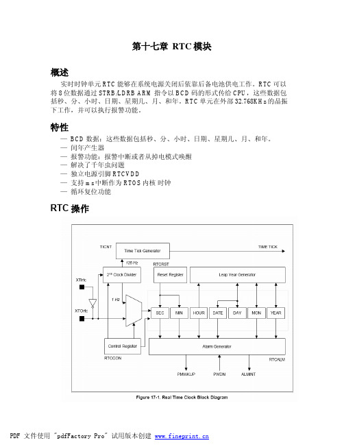
第十七章RTC模块概述实时时钟单元RTC能够在系统电源关闭后依靠后备电池供电工作。
RTC可以将8位数据通过STRB/LDRB ARM指令以BCD码的形式传给CPU,这些数据包括秒、分、小时、日期、星期几、月、和年。
RTC单元在外部32.768KHz的晶振下工作,并可以执行报警功能。
特性—BCD数据:这些数据包括秒、分、小时、日期、星期几、月、和年。
—闰年产生器—报警功能:报警中断或者从掉电模式唤醒—解决了千年虫问题—独立电源引脚RTCVDD—支持ms中断作为RTOS内核时钟—循环复位功能RTC操作闰年产生器闰年产生器可以基于BCDDATE、BCDMON、BCDYEAR决定每月的最后一天的日期是28、29、30还是31。
一个8位计数器只能表示两位BCD码,因此不能决定00年是否是闰年,例如它不能区别1900年还是2000年。
RTC模块通过硬件逻辑支持2000年为闰年(注意1900年不是闰年,2000年才是闰年)。
因此这两位“00”指的是2000年,而不是1900年。
寄存器读写要写BCD寄存器时必须要将RTCCON寄存器的0位置1,要显示秒、分、小时、日期、星期几、月、和年等时间,必须单独读取BCDSEC, BCDMIN, BCDHOUR, BCDDAY, BCDDATE, BCDMON, and BCDYEAR寄存器的值。
但是这中间可能存在1秒钟的偏差,因为要读多个寄存器。
例如,用户读到的结果是2059年12月31日23点59分,如果读取BCDSEC寄存器的值是1-59则没问题,但是如果是0,由于存在这1s钟的偏差,时间将变成2060年1月1日0时0分。
这种情况下,应该重新读取BCDYEAR – BCDSEC寄存器的值。
后备电池操作即使系统电源关闭,RTC模块可以由后备电池通过RTCVDD引脚供电。
当系统电源关闭时,CPU和RTC的接口应该被阻塞,后备电池应该只驱动晶振电路和BCD计数器,以最小化功耗。
第二章、TWIDO系列PLC介绍2-1 系列构成2-2 TWIDO主要功能2-3 安装与接线2-4 I/O地址分配2-5 TWIDO语言对象-内部软元件说明2-1 系列构成掌握要点:TWIDO 系列PLC介绍了解TWIDO系列PLC的系统构成。
2-1-1 CPU、I/O说明:TWIDO是一体化的小型PLC,由本体和扩展单元组成。
本体:集成了CPU,存储器,电源,输入、输出几部分。
Twido 控制器有以下两种模式CPU:一体型模块型一体型控制器包括:10 I/Os TWDLCAA 10DRF 不可扩展16 I/Os TWDLCAA 16DRF 不可扩展24 I/Os TWDLCAA 24DRF 可扩展4个模块40 I/Os TWDLCAA 40DRF 可扩展7个模块TWDLCAE 40DRF 可扩展7个模块,带以太网接口模块型控制器包括:20 I/Os TWDLMDA 20DTK 可扩展4个模块TWDLMDA 20DUK 可扩展4个模块TWDLMDA 20DRT 可扩展7个模块40 I/Os TWDLMDA 40DTK 可扩展7个模块TWDLMDA 40DUK 可扩展7个模块以下是控制器列表:扩展:本体通过连接扩展单元增加I/O点数和特殊功能(如AD/DA,通讯接口)。
数字量I/O或继电器类型的15个扩展模块模拟量I/O类型的8个扩展模块有多种点数组合、输出类型供用户选择下表为数字量和继电器扩展I/O模块:下表列出了模拟量扩展I/O模块:下表列出了可用选件:2 个连接器(20引脚)TWDFCN2K20 2 个连接器(26引脚)TWDFCN2K26 TWDLCAA40DRF 和TWDLCAE40DRF系列一体型基控制器具有的高级集成特征:内置100Base-TX 以太网端口:仅TWDLCAE40DRF板上的实时时钟(RTC):TWDLCAA40DRF和TWDLCAE40DRF第四个高速计数器(FC):TWDLCAA40DRF和TWDLCAE40DRF外部电池:TWDLCAA40DRF和TWDLCAE40DRF另外用户可选择两种编程设备对TWIDO进行编程和监控:* 安装了编程软件的计算机;专用掌上电脑。
样例程序:RTC 模块的使用 1. 简介本程序功能如下: 实现RTC 基本功能,每1 秒触发中断,使与P10_0的LED 以周期为2秒闪烁, 每5s 触发中断,使与P10_1的LED 以周期为10秒闪烁。
涉及到的模块有:RTC ,I/O 。
2. XE164F/XE164FM 的RTC 模块介绍 XE164F/XE164FM 的实时时钟(RTC )模块有一组预分频器和定时器级联构成,主要用来长时间记时。
RTC 由三个模块组成:8:1分频器、16位定时器、32位RTC 定时器模块。
特点:l 48位定时器,测量长时间间隔。
l 可用做系统时钟,指示当前时间和日期。
l 可分为5个定时器,并且有相应中断。
32位RTC 定时器可分为: l 10-bit 定时器 CNT0。
l 6-bit 定时器CNT1。
l 6-bit 定时器CNT2。
l 10-bit 定时器 CNT3。
计数器均向上计数,且有对应的中断。
T14、CNT0、CNT1、CNT2、CNT3 的关系如下:定时器T14和COUNT0~COUNT3级联可构成48位定时器,最大可用时间跨度248个T14输入时钟,若不进行预分频,计数频率为32kHz 时,该时间值将超过200年。
3. 操作流程B ySA CL (W H ) 刘志东4. DAvE 配置4.1 New Project:选择XE164F/XE164FMXE164F XE164FM4.2 The project settings XE164FB ySA CL (W H ) 刘志东XE164FMSystem clock XE164FXE164FMB ySA CL (W H ) 刘志东4.3 RTC 配置(XE164F 和XE164FM 的配置基本相同,以XE164F 为例) 使能RTC 模块,使能预分频,RTC 模块运行在同步模式下设定T14时基为1ms设定CNT0 中断周期为1s ,CNT1 中断周期为5s ,B ySA C L (W H ) 刘志东允许RTC 模块中断请求,运行CNT0、CNT1中断请求配置RTC 中断优先级:将RTC INT 从右边拖到左边表格对应的位置。
plc的rtc模块用法
PLC的RTC模块用法
PLC是一种可编程逻辑控制器,用于自动化控制和监控系统。
PLC常用于汽车、机器人、制造业、能源等领域。
其中,RTC模块是PLC的重要组成部分,它可以实现时间管理、计时、日期显示等功能。
本文将详细介绍PLC的RTC模块的用法。
1. 什么是RTC模块
RTC(Real Time Clock)即实时时钟模块,是一种实时时钟芯片,通过电池供电,使得PLC能够在断电后保存时间数据。
RTC芯片有多种类型,如DS1302、DS1307等,这些芯片都支持I2C总线协议与PLC进行通信。
与PLC内置的定时器不同,RTC模块具有更高的精度和更低的功耗,可以长期稳定运行。
2. RTC模块的功能
RTC模块的主要功能有以下几个:
(1) 实现时间管理:RTC模块可以保存当前时间和日期,PLC可以通过读取RTC 模块的数据,实现时间管理和控制。
(2) 实现计时和计数:RTC模块可以实现精确计时和计数,可以应用于流程控制、计时等功能中。
(3) 实现日期显示:RTC模块可以将保存的日期数据转换为人们容易理解的格式,并显示在PLC的触摸屏上。
(4) 实现报警功能:RTC模块可以设置报警时间,当达到设定时间时,触发PLC 的报警输出。
(5) 实现特殊功能:一些高级RTC芯片内置温度传感器、电压监测等功能,可以用于温度控制、电池电压监测等特殊应用中。
3. RTC模块的连接
RTC模块与PLC的连接主要有以下两种方式:
(1) I2C接口连接方式
这种连接方式需要用到I2C总线接口,将RTC的SDA(串行数据线)、SCL(串行时钟线)接到PLC的I2C总线输入端,同时将RTC的VCC(电源+)和GND (电源-)接到PLC的电源输出端,如下图所示:
 SPI接口连接方式
这种连接方式需要用到SPI总线接口,将RTC的MOSI(主设备串行输入)、MISO(主设备串行输出)、SCK(时钟线)、CS(片选信号线)接到PLC的SPI 总线输入端,同时将RTC的VCC(电源+)和GND(电源-)接到PLC的电源输出端,如下图所示:
 初始化RTC模块,包括设置时钟频率、校准时钟、清除计时器等。
(2) 读取RTC模块的时钟数据,包括秒钟、分、时、日、月、星期、年等数据。
(3) 根据需要调整时钟数据,比如设置闹钟时间、修改时间等。
(4) 将调整后的时钟数据写入RTC模块,同时保存在PLC的存储器中。
(5) 通过读取时钟数据,实现各种时间管理和控制功能,比如显示日期时间、计时、计数、报警等。
下面以DS1302为例演示RTC模块的使用步骤。
(1) 初始化RTC模块
DS1302的初始化流程包括以下几个步骤:
设置时钟数据格式
DS1302_WriteByte (0x8E); 写保护命令
DS1302_WriteByte (0x00); 禁止写保护
DS1302_WriteByte (0x80); 使能RAM写入保护
DS1302_WriteByte (0x90); 格式:时分秒年月日周
校准时钟
DS1302_WriteByte (0xBE); 打开时钟使能
DS1302_WriteByte (0x00); 关闭写保护
DS1302_WriteByte (0x00); 写入秒
DS1302_WriteByte (0x59); 写入分
DS1302_WriteByte (0x23); 写入时
DS1302_WriteByte (0x01); 写入日
DS1302_WriteByte (0x01); 写入月
DS1302_WriteByte (0x21); 写入年
DS1302_WriteByte (0x01); 写入星期
清除计时器
DS1302_WriteByte (0x8E); 写保护命令
DS1302_WriteByte (0x00); 禁止写保护
DS1302_WriteByte (0x90); 使能RAM写入保护
DS1302_WriteByte (0xBE); 打开时钟使能
DS1302_WriteByte (0x80); 关闭写保护
DS1302_WriteByte (0xC0); 使能计时器
DS1302_WriteByte (0x00); 写入0秒计时器
(2) 读取RTC模块的时钟数据
DS1302通过I2C总线发送读写命令,读取RTC模块的时钟数据并保存在PLC 内存中,代码示例如下:
读取秒钟
DS1302_WriteByte(0xbe); 打开时钟数据传输使能
Second = DS1302_ReadByte(); 读取秒数
DS1302_WriteByte(0x81); 关闭时钟数据传输使能
(3) 调整时钟数据
DS1302可以通过I2C总线发送写命令,修改时钟数据,比如设置闹钟时间,代码示例如下:
设置闹钟时间
DS1302_WriteByte (0x8E); 写保护命令
DS1302_WriteByte (0x00); 禁止写保护
DS1302_WriteByte (0x80); 使能RAM写入保护
DS1302_WriteByte (0x88); 设置闹钟的秒数为8秒
DS1302_WriteByte (0x59); 设置闹钟的分钟数为59分
DS1302_WriteByte (0x18); 设置闹钟的小时数为18时
DS1302_WriteByte (0x00); 写入日
DS1302_WriteByte (0x01); 写入月
DS1302_WriteByte (0x21); 写入年
DS1302_WriteByte (0x01); 写入星期
(4) 写入时钟数据
DS1302可以通过I2C总线发送写命令,将调整后的时钟数据写入RTC模块和PLC内存中,代码示例如下:
写入时钟数据
DS1302_WriteByte (0xBE); 打开时钟使能
DS1302_WriteByte (0x80); 关闭写保护
DS1302_WriteByte (0x80); 写入秒数
DS1302_WriteByte (0x59); 写入分数
DS1302_WriteByte (0x23); 写入小时数
DS1302_WriteByte (0x01); 写入日期
DS1302_WriteByte (0x01); 写入月份
DS1302_WriteByte (0x21); 写入年份
DS1302_WriteByte (0x01); 写入星期
DS1302_WriteByte (0x00); 关闭时钟使能
(5) 时间管理和控制
DS1302可以读取当前时间和日期,实现各种时间管理和控制功能,比如显示日期时间、计时、计数、报警等。
代码示例如下:
读取时间数据
DS1302_ReadTime(&hour, &minute, &second, &day, &month, &year, &weekday);
显示日期时间
printf("The current date and time
is %04d-%02d-%02d %02d:%02d:%02d\n", year, month, day, hour, minute, second);
计时
while(1){
t = DS1302_GetTime();
printf("The elapsed time is %d seconds\n", t);
Sleep(1000);延时1秒
}
计数
while(1){
n = DS1302_GetCount();
printf("The count value is %d \n", n);
}
报警
while(1){
if(DS1302_AlarmTriggered()){
printf("The alarm is triggered!");
}
}
5. 总结
RTC模块是PLC的重要组成部分,可以实现时间管理、计时、日期显示、报警等功能。
不同类型的RTC芯片有不同的功能和接口,需要根据实际应用选择。
使用RTC模块需要进行初始化、读取、调整、写入、时间管理等步骤,需要注意时钟精度和电源管理等问题。
掌握RTC模块的使用方法,可以为自动化控制和监控系统提供更精确的时间支持。