KLM5516工业级16口以太网交换机说明书
- 格式:docx
- 大小:214.52 KB
- 文档页数:6


可靠性目录目录第1章 VRRP配置.................................................................................................................1-11.1 VRRP简介.........................................................................................................................1-11.2 VRRP配置.........................................................................................................................1-21.2.1 设定虚拟IP地址是否可以使用ping命令ping通...................................................1-31.2.2 设置MAC地址和虚拟IP地址的对应关系..............................................................1-31.2.3 添加或删除虚拟IP地址..........................................................................................1-41.2.4 设置备份组的优先级...............................................................................................1-51.2.5 设置备份组的抢占方式...........................................................................................1-51.2.6 设置认证方式及认证字...........................................................................................1-61.2.7 设置VRRP的定时器..............................................................................................1-71.2.8 设置监视指定接口...................................................................................................1-71.3 VRRP显示和调试..............................................................................................................1-81.4 VRRP典型配置举例..........................................................................................................1-91.4.1 VRRP单备份组举例................................................................................................1-91.4.2 VRRP监视接口举例..............................................................................................1-111.4.3 VRRP多备份组举例..............................................................................................1-131.5 VRRP故障诊断与排错.....................................................................................................1-15第1章 VRRP配置1.1 VRRP简介VRRP(Virtual Router Redundancy Protocol)是一种容错协议。

以太网交换机使用说明书目录物品清单 (4)第一章用户手册简介 (5)1.1 用途 (5)1.2 约定 (5)1.3 用户手册概述 (5)第二章产品概述 (6)2.1 产品简介 (6)2.2 产品特性 (6)2.2.1 主要特性 (6)2.2.2 规格说明 (7)第三章安装指南 (8)3.1 安装 (8)3.1.1 安装在桌面上的方法 (8)3.1.2 安装在机架上的方法 (8)3.1.3 加电 (8)3.2 交换机的外观 (8)3.2.1 前面板 (8)3.2.2 后面板 (10)3.3 注意事项 (10)第四章交换机基本概念 (12)4.1 系统配置 (12)4.1.1 系统信息 (12)4.1.2 IP地址参数 (12)4.1.3 文件传输 (12)4.1.4 保存与复位 (13)4.2 端口管理 (13)4.2.1 端口参数 (13)4.2.2 端口监控 (14)4.2.3 端口描述 (14)4.2.4 端口统计与端口状态 (14)4.2.5 端口带宽 (15)4.2.6 端口广播风暴 (15)4.3 网络配置 (15)4.3.1 最大老化时间与动态地址表 (15)4.3.2 静态地址表 (16)4.3.3 静态安全地址表 (16)4.3.4 Ping检测 (16)4.4 虚拟局域网管理 (16)4.4.1 VLAN模式配置 (17)4.4.2 Global VID配置 (18)4.4.3 VLAN配置 (18)VLAN组 (19)4.4.4 MTU4.5 Trunk配置 (19)4.6 优先级管理 (20)4.6.1 优先级配置 (20)4.6.2 端口优先级表 (20)4.6.3 TOS优先级 (20)4.6.4 802.1p优先级 (20)4.6.5 802.1p优先级映射表 (21)第五章 WEB管理 (22)5.1 概述 (22)5.2 WEB管理的连接 (22)5.2.1 准备工作 (22)5.2.2 连接 (25)5.3 WEB管理界面及操作方法 (26)5.3.1 系统配置 (27)5.3.2 端口管理 (30)5.3.3 网络配置 (37)5.3.4 VLAN管理 (41)5.3.5 Trunk配置 (45)5.3.6 优先级管理 (46)第六章带外管理 (52)6.1 概述 (52)6.2 带外(out-of-out)的连接方法 (52)6.3 带外管理的界面及操作方法 (53)6.4 CLI命令使用说明 (53)6.4.1 语法帮助 (53)6.4.2 命令帮助使用说明 (53)6.4.3 常用命令 (54)管理 (58)第七章 Telnet7.1 概述 (58)7.2 Telnet的连接方法 (58)7.3 连接 (60)附录A RJ-45插座/连接器引脚详细说明 (62)物品清单小心打开包装盒,检查包装盒里应有的配件:一台交换机一根交流电源线一根串口线一本用户手册两个L型支架(KN-S1008M+除外)如果发现包装盒内产品有所损坏或者任何配件短缺的情况,请及时和当地经销商联系。

目录第1章 S5516以太网交换机介绍.........................................................................................1-11.1 S5516以太网交换机简介............................................................................................1-11.2 S5516以太网交换机的体系结构..................................................................................1-11.3 S5516交换机功能特性列表........................................................................................1-3第2章 S5516以太网交换机用户接口..................................................................................2-12.1 配置环境搭建.............................................................................................................2-12.2 命令行接口................................................................................................................2-72.2.1 命令行模式......................................................................................................2-82.2.2 命令行在线帮助.............................................................................................2-102.2.3 命令行错误信息..............................................................................................2-132.2.4 历史命令........................................................................................................2-142.2.5 编辑特性.......................................................................................................2-142.2.6 显示特性.......................................................................................................2-15第3章终端服务..................................................................................................................3-13.1 终端服务简介.............................................................................................................3-13.2 配置口终端服务......................................................................................3-13.3 Telnet终端服务.........................................................................................................3-13.3.1 Telnet服务种类................................................................................................3-13.3.2 建立Telnet连接..............................................................................................3-23.3.3 Telnet连接的监控与维护..................................................................................3-2第4章系统管理..................................................................................................................4-14.1 文件系统配置.............................................................................................................4-14.1.1 文件系统简介...................................................................................................4-14.1.2 目录操作.........................................................................................................4-14.1.3 文件操作..........................................................................................................4-14.1.4 存储设备操作..................................................................................................4-24.1.5 文件系统操作..................................................................................................4-24.1.6 文件系统使用举例............................................................................................4-24.2 配置文件管理............................................................................................................4-34.2.1 配置文件内容及格式.........................................................................................4-34.2.2 查看S5516以太网交换机的当前配置和起始配置................................................4-34.2.3 修改和保存当前配置.........................................................................................4-44.2.4 擦除Flash中配置文件.....................................................................................4-44.3 FTP配置...................................................................................................................4-44.3.1 FTP简介.........................................................................................................4-44.3.2 FTP服务器配置任务列表..................................................................................4-54.3.3 启动/关闭FTP服务器......................................................................................4-54.3.4 配置FTP服务器的验证和授权..........................................................................4-54.3.5 配置FTP服务器的运行参数..............................................................................4-64.3.6 FTP服务器的监控与维护..................................................................................4-64.3.7 FTP客户端介绍...............................................................................................4-74.4 维护调试工具............................................................................................................4-74.4.1 show命令查看系统状态和系统信息...................................................................4-74.4.2 系统基本配置及管理.........................................................................................4-84.4.3 网络连接的测试工具.........................................................................................4-94.4.4 日志功能.......................................................................................................4-114.4.5 调试功能........................................................................................................4-174.5 MAC地址表管理......................................................................................................4-184.5.1 MAC地址表管理简介......................................................................................4-184.5.2 MAC地址表管理配置任务列表........................................................................4-184.5.3 设置MAC地址表项........................................................................................4-194.5.4 设置系统MAC地址老化时间..........................................................................4-194.5.5 关闭/开启MAC地址学习功能........................................................................4-204.5.6 MAC地址表管理的监控与维护........................................................................4-204.5.7 地址表管理典型配置举例................................................................................4-224.6 设备管理.................................................................................................................4-234.6.1 设备管理简介................................................................................................4-234.6.2 设备管理配置任务列表....................................................................................4-234.6.3 复位单板........................................................................................................4-234.6.4 设备管理的监控与维护....................................................................................4-23第5章网管配置..................................................................................................................5-15.1 SNMP配置................................................................................................................5-15.1.1 SNMP协议简介...............................................................................................5-15.1.2 SNMP配置......................................................................................................5-35.1.3 SNMP的监控与维护.........................................................................................5-75.1.4 SNMP典型配置举例.........................................................................................5-85.2 RMON配置...............................................................................................................5-95.2.1 RMON简介.....................................................................................................5-95.2.2 RMON配置...................................................................................................5-105.2.3 RMON的监控与维护......................................................................................5-125.2.4 RMON典型配置举例......................................................................................5-145.3 SMON配置.............................................................................................................5-165.3.1 SMON简介...................................................................................................5-165.3.2 SMON配置...................................................................................................5-165.3.3 SMON的监控与维护......................................................................................5-17第6章 Line配置..................................................................................................................6-16.1 Line简介...................................................................................................................6-16.1.1 Line配置概述..................................................................................................6-16.1.2 Line的编号......................................................................................................6-16.2 Line配置...................................................................................................................6-26.2.1 进入Line配置模式...........................................................................................6-26.2.2 配置异步接口属性............................................................................................6-36.2.3 配置终端属性...................................................................................................6-46.2.4 设置优先级......................................................................................................6-56.2.5 配置Modem属性.............................................................................................6-56.2.6 配置重定向功能................................................................................................6-56.3 Line的监控与维护......................................................................................................6-56.3.1 显示Line的用户使用信息.................................................................................6-56.3.2 显示Line的物理属性和一些配置.......................................................................6-5第1章 S5516以太网交换机介绍1.1 S5516以太网交换机简介随着Internet市场的不断发展传真可视电话Video On Demand等宽带业务领域延伸以太网接入因其成本低速度高而倍受市场的关注华为公司根据不同的客户类型需求Quidway S5516以太网交换机是华为公司自主开发的面向城域网和企业网用户的L2/L3以太网交换机三层交换功能及IP路由功能1个10Base-T 固定以太网端口及1个Console口大型企业和园区网的汇聚设备以及中小型企业网的骨干设备如华为Quidway NetEngine80/16E/08/05È绪ΪQuidwayS8016/S6506ÏÂÐпɻã½Ó¶à¸ö¹¤×÷×鼶ÒÔÌ«Íø½»»»»úΪ¸÷²ã´Î¶àÑùµÄÁ¬Íø½â¾ö·½°¸l Internet宽带接入l企业网和园区网组网l提供多播服务和多播路由功能视频服务及视频点播服务在本文中1.2 S5516以太网交换机的体系结构S5516以太网交换机的硬件设计采用了业界流行的网络产品结构其中l交换转发平面与网络接口根据地址转发表同时硬件完成VLAN优先级端口聚合等功能配置协议处理该平面由CPU系统来完成包括配置管理路由和TCP/IP协议栈主要完成网络层协议及数据链路层相关协议和管理报文的处理图1-1 S5516以太网交换机软件体系结构图1.3 S5516交换机功能特性列表表1-1 功能特性列表业务实现线速二/三层交换l所有端口支持线速转发l32Gbps交换容量l包转发率24Mpps交换模式l存储转发模式流控l支持IEEE 802.3x 流控l背压式流控VLAN l最多支持4K个VLANl符合IEEE 802.1Q标准l支持基于端口的VLANl支持GARP VLAN注册协议l支持VTP协议组播l GMRPl IGMP Snooping生成树支持生成树协议及快速生成树协议业务实现安全特性l支持二四层包过滤源/目的MAC地址l用户分级管理和口令保护QoS l支持带宽管理MAC地址TCP/UDP 端口号和ToS / Diffserv值流控的粒度为64kbpsl支持优先级MAC地址TCP/UDP 端口号和ToS / Diffserv值支持SPTFTP协议加载升级管理l支持命令行配置l支持Telnet远程配置l支持配置口配置l支持远端拨号l支持SNMP管理29组MIBTracertl支持通过Modem拨号第2章 S5516以太网交换机用户接口2.1 配置环境搭建S5516以太网交换机支持用户进行本地与远程配置1. 通过配置口搭建本地配置环境第一步建立本地配置环境或终端图2-1 通过配置口搭建本地配置环境第二步如Windows 3.X的Terminal或Windows9X的超级终端等设置终端通信参数为8位数据位无校验和无流控如图2-2至图2-4所示图2-2 新建连接图2-3 连接端口设置图2-4 端口通信参数设置第三步自动进行配置否则会显示S5516自检信息直到出现命令行提示符键入命令需要帮助可以随时键入2. 通过Telnet搭建配置环境如果S5516不是第一次上电在VLAN接口模式下使用ip address命令并已指定属于各个VLAN 的以太网端口然后对S5516进行配置通过Telnet配置S5516前需要对S5516的VLAN进行配置STP及VLAN配置VLAN配置第一步先通过Console口在S5516上进行欲登录的Telnet用户的授权验证Quidway(config-line-vty0)# password xxxxQuidway(config)# enable password xxxx&说明如果没有配置口令而通过Telnet登录password required, but none set.第二步建立配置环境图2-5 通过局域网搭建本地配置环境第三步并设置其终端类型为VT100图2-6 运行Telnet程序图2-7 与S5516建立Telnet连接&说明第四步在微机上键入S5516主机IP地址输入已设置的登录口令如Quidway>如果出现的提示S5516以太网交换机最多允许5个telnet用户第五步配置S5516或查看S5516运行状态必须输入已设置的口令?关于具体的命令请参考以后各章节通过Telnet配置S5516时修改后可能会导致Telnet连接断开如有必要修改若S5516的IP地址改变重新建立Telnet连接3. 通过Modem拨号与S5516配置口连接搭建远程配置环境第一步先通过Console口在S5516上进行欲登录的Modem用户的授权验证xxxx是欲设置的该Modem用户登录口令xxxx是欲设置的该Modem用户由普通用户模式进入特权用户模式的口令Modem用户登录缺省需要口令的验证在S5516上通过以下命令将Console口配置为Modem方式如图2-8所示在微机的串口和S5516的Console口分别挂接ModemS5516图2-8 搭建远程配置环境第四步与S5516建立连接图2-9 拨号号码设置图2-10 在远地微机上拨号第五步出现命令行提示符如果想要进入特权用户模式需要帮助可以随时键入2.2 命令行接口S5516以太网交换机向用户提供一系列配置命令以及命令行接口命令行接口有如下特性l通过Telnet进行本地或远程配置l配置命令分级保护l用户可以随时键入以获得在线帮助如TracertѸËÙÕï¶ÏÍøÂçÊÇ·ñÕý³£ÄÚÈÝÏ꾡µÄµ÷ÊÔÐÅÏ¢l用Telnet命令直接登录并管理其它S5516·½±ãÓû§ÉÏÔØl提供类似Doskey的功能l命令行解释器对关键字采取不完全匹配的搜索方法如show命令2.2.1 命令行模式S5516以太网交换机的命令行采用分级保护方式各命令模式是针对不同的配置要求实现的比如它只完成查看运行状态和统计信息的简单功能如果设置了enablepassword¼üÈëconfig terminal进入全局配置模式键入不同的配置命令进入相应的配置模式l普通用户模式l特权用户模式l全局配置模式l千兆以太网端口配置模式l OSPF协议配置模式l RIP协议配置模式l VLAN接口配置模式l VLAN配置模式l VTP配置模式l Line配置模式各命令模式的功能特性表2-1 命令模式功能特性列表命令模式功能提示符进入命令退出命令普通用户模式查看交换机的简单运行状态和统计信息Quidway>与交换机建立连接即进入exit断开与交换机连接特权用户模式查看交换机的全部运行状态和统计信息interface gigabitethernet 1/1或interface gigabitethernet 2/1exit返回全局配置模式end返回特权用户模式OSPF协议配置模式配置OSPF协议参数Quidway(config-router-ospf)#在全局配置模式下键入routerospfexit返回全局配置配置模式end返回特权用户模式RIP协议配置模式配置RIP协议参数Quidway(config-router-rip)#在全局配置模式下键入routerripexit返回全局配置模式end返回特权用户模式VLAN接口配置模式配置VLAN和VLAN汇聚对应的IP接口参数Quidway(config-VLAN-Interface1)#在全局配置模式下键入&说明缺省为QuidwayÀ¨ºÅÖбíÃ÷µ±Ç°µÄÅäÖÃģʽ>表示特权用户l helpl完全帮助l部分帮助通过上述各种在线帮助能够获取到帮助信息(1) 在任一配置模式下Quidway> helpHelp may be requested at any point in a command by enteringa question mark '?'. If nothing matches, the help list willbe empty and you must backup until entering a '?' shows theavailable options.Two styles of help are provided:1. Full help is available when you are ready to enter acommand argument (e.g. 'show ?') and describes each possibleargument.2. Partial help is provided when an abbreviated argument is entered and you want to know what arguments match the input(e.g. 'show use?').(2) 在任一命令模式下?Quidway# ?Privilege EXEC mode commands:Privilege EXEC mode commands:cd Change current directoryclear Enter clear command groupclock Manage the system clockconfigure Enter configuration modecopy Copy from one file to anotherdebug Debugging functionsdelete Delete a filedir List files on a filesystemdisable Turn off privileged EXEC mode commandsenable Turn on privileged EXEC mode commandserase Erase startup configurationexit Exit from the EXECformat Format file systemftp Open FTP connectionhelp Description of the interactive help systemlock Lock the terminalmkdir Create a new directorymore Display the contents of a filemove Move from one file to anotherno Negate a command or set its defaultsping Send echo messagesptvl Pvtl realted processpwd Display current working directoryrename Rename a filereset Reset slotrmdir Remove an existing directorysend Send a message to other tty linesshow Show running system informationsqueeze Deleted file permanentlytelnet Open a TELNET connectionterminal Set terminal line parameterstracert Trace route to destinationundelete Recover a deleted filewrite Write running configuration(3) 键入一命令?如果该位置为关键字Quidway# show ?aaa Display AAA informationaccess-lists Display ACL's contentsacl Access Control Listarp Show ARP Entrychannel Show informational channel's contentsclock Display the system clockconfig-user Can login or logout userscontroller Display controller informationdebugging Show current setting of debugging switchdhcp-server Show the relevant information of DHCP server egress Mapping rule for egress queuefans Fansfib fibflow-action Flow actionftp-server Display information about FTP serverftp-user Display information about FTP usersgarp Generic attribute registration protocolgmrp GARP multicast registration protocolgvrp GARP vlan registration protocolhistory Display the session command historyigmp-snooping IGMP Snoopinginterface Display interface informationip Global IP configuration subcommandsipfdb FDBline TTY line informationlink-aggregation Ports aggregation modelogging Show informational center configuration and contents mac-address Configure MAC addressmemory Show mem infomonitor-port Show the monitor portrmon RMON informationroute-map Display configured route-mapsrouter Show router informationrule-map Rule for separating streamrunning-config Current operating configurationslot Slotsmon SMON informationsnmp Snmp statisticsspanning-tree Spanning Tree Protocolstartup-config Contents of startup configurationtask Show system tasktcp Status of TCP connectionstime-range Time rangetraffic Traffic modelusers Display information about terminal linesversion System hardware and software statusvlan Vlan configuration informationvtp VTP configuration(4) 键入一命令?如果该位置为参数Quidway(config)# interface gigabitethernet ?<1-4> Slot numberQuidway(config)# interface gigabitethernet 1?/Quidway(config)# interface gigabitethernet 1/?<1-4>Quidway(config)# interface gigabitethernet 1/1 ?<cr><cr>表示该位置无参数直接键入回车即可执行其后紧接Quidway# d?debug delete dir disable(6) 键入一命令?列出命令以该字符串开头的所有关键字均可以通过在特权用户模式下执行terminal language 命令切换为中文显示如果通过语法检查否则向用户报告错误信息表2-2 命令行常见错误信息表英文错误信息错误原因没有查找到命令没有查找到关键字Unrecognized command参数类型错参数值越界Incomplete command输入命令不完整Too many parameters输入参数太多Ambiguous command输入参数不明确2.2.4 历史命令命令行接口提供类似Doskey功能用户可以随时调用命令行接口保存的历史命令命令行接口为每个用户最多可以保存10条历史命令表2-3 访问历史命令操作按键结果访问上一条历史命令上光标键如果还有更早的历史命令否则响铃警告则取出下一条历史命令响铃警告用光标键对历史命令进行访问但对于Windows 9X超级终端光标键会无效这时可以用组合键和来代替2.2.5 编辑特性命令行接口提供了基本的命令编辑功能每条命令的最大长度为256个字符表2-4 编辑功能表按键功能普通按键若编辑缓冲区未满并向右移动光标响铃告警光标前移则响铃告警若已经到达命令尾左光标键若已经到达命令首右光标键若已经到达命令尾上下光标键显示历史命令2.2.6 显示特性命令行接口提供了如下的显示特性提示信息和帮助信息可以用中英文两种语言显示提供了暂停功能如表2-5所示Ctrl+CÔÝÍ£ÏÔʾʱ¼üÈë¿Õ¸ñ¼ü¼ÌÐøÏÔʾÏÂÒ»ÆÁÐÅÏ¢第3章终端服务3.1 终端服务简介S5516以太网交换机向用户提供以下进入命令行接口的终端服务l通过Console口利用Modem拨号登录到S5516进行远程配置3.2 配置口终端服务通过Console口即控制台配置环境的搭建参见第二章相关内容表3-1 Console口终端服务特性服务特性回显方式本地不回显终端类型VT100波特率9600bit/s数据位8位奇偶校验无停止位1位流控无二进制传输协议XModem3.3 Telnet终端服务3.3.1 Telnet服务种类Telnet协议在TCP/IP协议族中属于应用层协议S5516以太网交换机提供的Telnet服务包括如图4-1所示对S5516进行配置管理S5516所示服务特性字符模式VT100表3-4 Telnet连接的监控与维护操作命令显示当前Line连接情况show users显示每条Line连接情况show users all显示当前建立的所有TCP连接情况show tcp briefshow users命令只能显示与S5516建立连接的Telnet客户使用的端口则需要执行show tcp brief命令包括Telnet客户和Telnet服务器连接查看每条Line的连接情况Quidway# show tcp briefLocalAddress LocalPort ForeignAddress ForeignPort State129.102.100.142 23 129.102.001.092 1038 ESTABLISHED 0.0.0.0 23 0.0.0.0 0 LISTEN以上显示信息表示该TCP连接的本地IP地址为129.102.100.142远地IP地址为129.102.001.92另外本地有一个对23号端口监听的服务器第4章系统管理4.1 文件系统配置4.1.1 文件系统简介文件系统实现的主要功能为管理存储设备目录的管理创建修改以及显示文件的内容4.1.2 目录操作文件系统可以创建并删除目录请在特权用户模式下进行下列配置恢复删除的文件显示文件的内容拷贝文件显示指定的文件的信息表4-2 文件操作操作命令删除文件delete file-url恢复删除文件undelete file-url彻底删除回收站中的文件squeeze file-url显示文件的内容more[ / binary ] file-url重新命名文件rename fileurl-source fileurl-dest拷贝文件copy fileurl-source fileurl-dest移动文件move fileurl-source fileurl-dest显示目录或文件信息dir [ / all ] [ file-url ]4.1.4 存储设备操作文件系统可以格式化指定的存储设备表4-3 存储设备操作操作命令格式化存储设备format filesystem4.1.5 文件系统操作用户通过命令可以修改当前文件系统的提示方式表4-4 文件系统操作操作命令文件系统的提示方式file prompt { alert | quiet }4.1.6 文件系统使用举例Quidway# format flash:All sectors will be erased, proceed? [confirm]yFormat flash: completedQuidway# cd flash:/Quidway# pwdflash:/Quidway# mkdir testQuidway# dirDirectory of *0 drw- 0 Mar 09 2002 12:01:44 test523776 bytes total (476160 bytes free)4.2 配置文件管理4.2.1 配置文件内容及格式配置文件为一文本文件l以命令格式保存只保存非缺省的常数同一命令模式的命令组织在一起节与节之间通常用空行或注释行隔开开始的为注释行l节的顺序安排通常为物理端口配置路由协议配置等4.2.2 查看S5516以太网交换机的当前配置和起始配置S5516以太网交换机上电时因此将Flash中配置文件称为起始配置则S5516用缺省参数初始化S5516运行过程中正在生效的配置称为当前配置表4-5 查看S5516配置操作命令查看S5516的起始配置show startup-config查看S5516的当前配置show running-config&说明4.2.3 修改和保存当前配置用户通过命令行接口可以修改S5516以太网交换机当前配置需要用write命令保存当前配置到Flash中表4-6 保存当前配置操作命令保存当前配置write4.2.4 擦除Flash中配置文件用erase命令可以擦除S5516以太网交换机Flash中的配置文件S5516下次上电将采用缺省的配置参数进行初始化可以擦除Flash中配置文件可能会引起S5516软件和配置文件不匹配如加载了错误的配置文件表4-7 擦除Flash中配置文件操作命令擦除Flash中配置文件erase4.3 FTP配置4.3.1 FTP简介FTP协议在TCP/IP协议族中属于应用层协议FTP协议基于相应的文件系统实现S5516以太网交换机提供的FTP服务包括用户可以运行FTP客户端程序登录到服务器上l FTP Client服务可以输入FTP命令建立与远程FTP Server的连接并访问远程服务器上的文件表4-8 启动/关闭FTP服务器操作命令启动FTP服务器ftp server enable关闭FTP服务器no ftp serverFTP服务器可同时支持多个用户的访问FTP服务器执行相应的动作4.3.4 配置FTP服务器的验证和授权FTP服务器的授权信息是提供给FTP用户的顶级工作目录才能得到FTP服务器的服务例明文授权工作目录为c S5516文件系统支持的路径名配置FTP用户的验证信息在全局配置模式下Quidway(config)# user quidway ftp-directory c:/ftp/quidway4.3.5 配置FTP服务器的运行参数为了防止未授权用户的非法入侵则断开与该FTP客户端的连接表4-9 配置FTP服务器的超时断连时间操作命令配置FTP服务器的超时断连时间ftp timeout minute恢复FTP服务器的超时断连时间的缺省值no ftp timeout缺省情况下4.3.6 FTP服务器的监控与维护FTP服务器提供以下命令请在除普通用户模式以外的所有其它配置模式下进行下列操作包括FTP服务器支持的最大用户数和超时断连时间(1) 显示当前FTP服务器的配置情况FTP服务器已经启动现在登录的用户数为0个(2) 显示当前FTP用户的配置情况有一个FTP用户和FTP服务器建立了连接密码为huawei远地端口号为1074现在已经有2分钟没有向FTP服务器发送服务请求作为S5516提供给用户的一个附加功能是一个应用模块并键入FTP客户端的命令来进行相应的操作建立4.4 维护调试工具4.4.1 show命令查看系统状态和系统信息show命令根据功能可以划分为以下几类下面只介绍一些有关系统的show命令其中show version还可在普通用户模式下进行(1) 显示系统版本4.4.3 网络连接的测试工具1. pingping主要用于检查网络连接及主机是否可达表4-13 ping命令操作命令支持IP协议ping ping [ -a ip-address ] [ -c count ] [ -d ] [ -i { interface-type interface-number | interface-name } ] [ ip ] [ -n ] [ -p pattern ] [ -q ] [ -r ] [ -s packetsize ] [ -t timeout ] [ -v ] [ ip ]host各选项及参数意义详见命令参考手册ping命令章节l对每一ping报文的响应情况则输出报文序号l最后的统计信息接收报文数最大和平均值它主要用于检查网络连接是否可达tracert的执行过程是因此第一跳发送回一个ICMP错误消息以指明此数据包不能被发送TTL为2Õâ¸ö¹ý³Ì²»¶Ï½øÐÐÖ´ÐÐÕâЩ¹ý³ÌµÄÄ¿µÄÊǼǼÿһ¸öICMP TTL超时消息的源地址表4-14 tracert命令操作命令Trace Route tracert [ -f first-TTL ] [ -m max-TTL ] [ -p port ] [ -q nqueries ] [ -w timeout ] host该命令各选项及参数意义详见命令手册tracert命令章节Quidway# tracert 35.1.1.48traceroute to (35.1.1.48), 30 hops max, 56 byte packet1 (128.3.112.1) 19 ms 19 ms 0 ms2 (128.32.216.1) 39 ms 39 ms 19 ms3 (128.32.136.23) 39 ms 40 ms 39 ms4 (128.32.168.22) 39 ms 39 ms 39 ms5 128.32.197.4 (128.32.197.4) 40 ms 59 ms 59 ms6 131.119.2.5 (131.119.2.5) 59 ms 59 ms 59 ms7 129.140.70.13 (129.140.70.13) 99 ms 99 ms 80 ms8 129.140.71.6 (129.140.71.6) 139 ms 239 ms 319 ms9 129.140.81.7 (129.140.81.7) 220 ms 199 ms 199 ms10 (35.1.1.48) 239 ms 239 ms 239 ms从上面结果可以看出从源主机到目的地都经过了哪些网关Quidway# tracert 18.26.0.115traceroute to (18.26.0.115), 30 hops max1 (128.3.112.1) 0 ms 0 ms 0 ms2 (128.32.216.1) 19 ms 19 ms 19 ms3 (128.32.216.1) 39 ms 19 ms 19 ms4 (128.32.136.23) 19 ms 39 ms 39 ms5 (128.32.168.22) 20 ms 39 ms 39 ms6 128.32.197.4 (128.32.197.4) 59 ms 119 ms 39 ms7 131.119.2.5 (131.119.2.5) 59 ms 59 ms 39 ms8 129.140.70.13 (129.140.70.13) 80 ms 79 ms 99 ms9 129.140.71.6 (129.140.71.6) 139 ms 139 ms 159 ms10 129.140.81.7 (129.140.81.7) 199 ms 180 ms 300 ms11 129.140.72.17 (129.140.72.17) 300 ms 239 ms 239 ms12 * * *13 128.121.54.72 (128.121.54.72) 259 ms 499 ms 279 ms14 * * *15 * * *16 * * *17 * * *18 (18.26.0.115) 339 ms 279 ms 279 ms对以上显示内容的相应说明如下表4-15 tracert命令说明表显示内容内容说明tracertroute to (18.26.0.115)表示将要到达的目的主机名及IP地址40 bytes packet表示数据报40字节表示经由网关名0 ms 0 ms 0 ms 表示三份数据报的ICMP报文分别在0 ms0 ms收到以及哪些网关出现了故障它作为S5516系统软件模块的信息枢纽而存在并且能够进行细致的分类它通过与Debug程序的结合S5516以太网交换机的日志系统具有以下一些特性Console Telnet终端和哑终端logbuf 日志主机trapbuf SNMP六个方向的日志输出可按等级进行信息过滤可按模块进行信息过滤2. SYSLOG配置(1) 开启或关闭日志功能请在全局配置模式下进行下列操作表4-16 开启或关闭日志功能操作命令开启日志系统logging on关闭日志系统no logging on&说明在syslog开启时输出的原因对系统性能有一定的影响S5516的日志系统l通过Console口向本地控制台输出日志信息此功能有助于远程维护用于记录日志信息日志系统直接将日志信息发往日志主机供随时查看用于记录信息每个输出方向通过配置命令指定所需要的通道发送到相应的输出方向以及配置通道的过滤信息请在全局配置模式下进行下列配置表4-17 输出日志信息操作命令向Console方向输出信息set console channel { channel-number| channel-name }向Telnet终端或哑终端输出信息set monitor channel { channel-number | channel-name }向日志缓冲区输出信息set logging buffered [ size buffersize ][ channel{ channel-number | channel-name }]取消向日志缓冲区输出信息no logging buffered向日志主机输出信息set logging host host-ip-addr [ channel{ channel-number | channel-name }] [ facility local-number ] [ language{ chinese | english } ]取消向日志主机输出信息no logging host host-ip-addr向告警缓冲区输出信息set logging buffered [ size buffersize ][ channel{ channel-number | channel-name }]取消向告警缓冲区输出信息no trappings buffered向SNMP输出信息set snmp channel { channel-number | channel-name }目前它们是输出方向信息通道号缺省的信息通道名控制台0console监视终端1monitor日志主机2loghost日志缓冲区4logbuf告警缓冲区3trapbufsnmp5snmpagent&说明但首先需要开启信息中心(3) SYSLOG定义的优先级SYSLOG按信息的严重等级或紧急程度划分为八个等级采用的规则是越紧急的日志报文emergencies表示的等级为0debugging为7µ±ÉèÖÃÑÏÖصȼ¶ãÐֵΪdebugging时表4-18 syslog定义的优先级严重等级描述emergencies极其紧急的错误alerts需立即纠正的错误critical关键错误errors需关注但不关键的错误warnings警告设置允许PPP协议日志信息等级为debugging及以上的信息从控制台输出表4-19 定义信息通道的内容操作命令向信息通道中添加对于某模块某类信息的过滤记录enable source {modu-name | all } type { l og | trap | debug } [ level severity ] [ channel {channel-number | channel-name } ]删除信息通道中对于某模块某类信息的过滤记录disable source {modu-name | all } type { log | trap | debug } [ level severity ] [ channel {channel-number | channel-name } ]删除信息通道中关于某模块或全部模块的内容no source { modu-name | all } [ channel { channel-number | channel-name } ]modu-name是模块名level是信息重要级别在此级别以下的信息不输出channel-name是要设置的信息通道名它的模块名为all但对于不同信息通道告警。
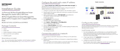
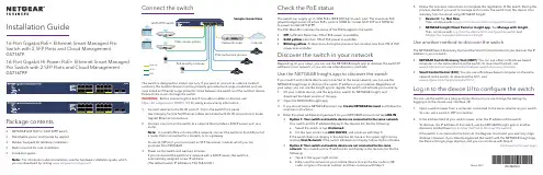
Installation Guide16-Port and 24-Port Gigabit Ethernet Smart Managed Pro Switch with 2 SFP Ports48-Port Gigabit Ethernet Smart Managed Pro Switch with 2 Copper and 2 Copper/SFP Combo PortsModels GS716Tv3, GS724Tv4 and GS748Tv5 Package Contents• Switch• Power cord• Rubber footpads for tabletop installation• Rack-mount kit for rack installation• Installation guideEthernet cables are not included.Note: For more information about installation, see the hardware installation guide, which you can download from https:///support/.Configure the switch with a static IP addressNote: If your network uses a DHCP server, this section does not apply. Godirectly to Connect the switch to a network.If you are using static IP addresses in your network, configure the switch IPaddress before you connect the switch to a network.1. Configure a computer with a static IP address in the 192.168.0.x subnet.2. Plug the switch into a power outlet and connect your computer to the switchusing an Ethernet cable.3. Open a web browser and enter 192.168.0.239 in the address bar.The default IP address of the switch is 192.168.0.239.A login page displays.4. Enter password for the password.The System Information page displays.5. Select System > Management > IP Configuration.The IP Configuration page displays.6. Select the Static IP Address radio button.7. Enter the static IP address, subnet mask, and default gateway IP address thatyou want to assign to the switch.8. Click the Apply button.Your settings are saved.Connect the switch to a network1. Connect device to the RJ-45 network ports or SFP port on the switch frontpanel.2. Connect an RJ45 port or SFP port on the switch to a network that includes aDHCP server.Note: In a small or home office network, connect the switch to the LAN portof a router, that in turn, is connected to an Internet modem.Configure the switchYou can configure the switch by using the local browser interface, or by installingthe Smart Control Center Utility (see Smart Control Center Utility) on yourWindows-based computer.Local browser access1. For initial configuration, open a web browser on a computer that is on thesame network and subnet as the switch and enter the switch’s IP address.If you are unsure how to determine the IP address of the switch, you can usethe Smart Control Center Utility.2. A login page displays. Enter password for the password.The System Information page displays.3. Configure the switch for your network.For information about switch configuration, see the user manual for yourswitch, which you can download from /support/.Sample connectionsNETGEAR, Inc.350 East Plumeria DriveSan Jose, CA 95134, USA NETGEAR INTL LTDFloor 1, Building 3, University Technology Centre Curraheen Road, CorkT12EF21, Ireland© NETGEAR, Inc., NETGEAR and the NETGEAR Logo are trademarks of NETGEAR, Inc. Any non‑NETGEAR trademarks are used for reference purposes only.SupportThank you for purchasing this NETGEAR product. You can visithttps:///support/ to register your product, get help, access the latest downloads and user manuals, and join our community. We recommend that you use only official NETGEAR support resources.Si ce produit est vendu au Canada, vous pouvez accéder à ce document en français canadien à https:///support/download/.(If this product is sold in Canada, you can access this document in Canadian French at https:///support/download/.)For regulatory compliance information including the EU Declaration of Conformity, visit https:///about/regulatory/.See the regulatory compliance document before connecting the power supply. Do not use this device outdoors. If you connect cables or devices that are outdoors to this device, see https:///000057103 for safety and warranty information.Smart Control Center UtilityThe Smart Control Center Utility runs on Windows-based computers. You can visit /support/, enter Smart Control Center in the search box, and click the Downloads button.Install the Smart Control Center UtilityNote: The Smart Control Center Utility requires Adobe Air. If Adobe Air is not detected during Smart Control Center Utility installation, you are prompted to allow Adobe Air to be installed.Note: For optimal discovery performance, we recommend that you restart your computer after installing the Smart Control Center Utility.Configure the switch with the Smart Control Center Utility1. Connect the computer to the network.The computer that is running the Smart Control Center Utility must be on the same network (with same broadcast domain) as the switch.2. Click the Discover button.The Smart Control Center Utility finds Smart Managed Switches on thenetwork and displays each switch’s MAC address, IP address, and modelnumber.If the utility does not discover your switch, verify that the cable connections are secure and that the computer’s IP address is in the same subnet as the switch, and click the Discover button.You might need to temporarily turn off the antivirus program, firewall, or both on the computer so that the utility can discover the switch.3. Select the switch that you want to configure.4. Click the Web Browser Access button.5. When prompted, enter the password.The default password is password.6. Click the Login button.The System Information page displays.7. Configure the switch for your network.For information about switch configuration, see the user manual for yourswitch, which you can download from /support/.8. When you are finished with the configuration, return the computer’s antivirusprogram and firewall to their usual settings. Troubleshooting tipsHere are some tips for correcting simple problems that might occur.• Be sure to power on your computer and switch in the following sequence:1. Turn on the switch and wait about two minutes.2. Turn on the computer and connect it to the switch.• Make sure the Ethernet cables are plugged in.For each powered-on computer connected to the switch, the corresponding switch LAN port status LED is lit.• Make sure the network settings of the computer are correct.In most cases, computers should be configured to obtain an IP addressthrough DHCP. If your network uses static IP addresses, be sure that theswitch and computer are configured with valid IP addresses. For morei nformation, see the software administration manual.September 2019。
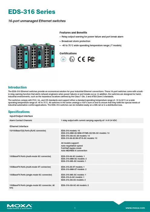
EDS-316Series16-port unmanaged Ethernet switchesFeatures and Benefits•Relay output warning for power failure and port break alarm•Broadcast storm protection•-40to75°C wide operating temperature range(-T models)CertificationsIntroductionThe EDS-316Ethernet switches provide an economical solution for your industrial Ethernet connections.These16-port switches come with a built-in relay warning function that alerts network engineers when power failures or port breaks occur.In addition,the switches are designed for harsh industrial environments,such as the hazardous locations defined by the Class1Div.2and ATEX Zone2standards.The switches comply with FCC,UL,and CE standards and support either a standard operating temperature range of-10to60°C or a wide operating temperature range of-40to75°C.All switches in the series undergo a100%burn-in test to ensure that they fulfill the special needs of industrial automation control applications.The EDS-316switches can be installed easily on a DIN rail or in a distribution box. SpecificationsInput/Output InterfaceAlarm Contact Channels1relay output with current carrying capacity of1A@24VDCEthernet Interface10/100BaseT(X)Ports(RJ45connector)EDS-316models:16EDS-316-MM-SC/MM-ST/MS-SC/SS-SC models:14EDS-316-SS-SC-80models:14EDS-316-M-SC/M-ST/S-SC models:15All models support:Auto negotiation speedFull/Half duplex modeAuto MDI/MDI-X connection100BaseFX Ports(multi-mode SC connector)EDS-316-M-SC models:1EDS-316-MM-SC models:2EDS-316-MS-SC models:1100BaseFX Ports(multi-mode ST connector)EDS-316-M-ST models:1EDS-316-MM-ST models:2100BaseFX Ports(single-mode SC connector)EDS-316-MS-SC models:1EDS-316-S-SC models:1EDS-316-SS-SC models:2EDS-316-SS-SC-80models:2100BaseFX Ports(single-mode SC connector,80km)Standards IEEE802.3for10BaseTIEEE802.3u for100BaseT(X)and100BaseFXIEEE802.3x for flow controlOptical Fiber800Typical Distance4km5km40km80kmWavelength Typical(nm)130013101550TX Range(nm)1260to13601280to13401530to1570RX Range(nm)1100to16001100to16001100to1600Optical PowerTX Range(dBm)-10to-200to-50to-5RX Range(dBm)-3to-32-3to-34-3to-34Link Budget(dB)122929DispersionPenalty(dB)311Note:When connecting a single-mode fiber transceiver,we recommend using anattenuator to prevent damage caused by excessive optical power.Note:Compute the“typical distance”of a specific fiber transceiver as follows:Linkbudget(dB)>dispersion penalty(dB)+total link loss(dB).DIP Switch ConfigurationEthernet Interface Port break alarmSwitch PropertiesPacket Buffer Size 1.25MbitsMAC Table Size4KProcessing Type Store and ForwardPower ParametersInput Current Non-fiber models:0.34A@24VDCFiber models:0.4A@24VDCConnection1removable6-contact terminal block(s)Operating Voltage9.6to60VDCInput Voltage12/24/48VDCRedundant dual inputsReverse Polarity Protection SupportedOverload Current Protection SupportedPhysical CharacteristicsHousing MetalIP Rating IP30Dimensions80.1x135x105mm(3.15x5.31x4.13in) Weight1140g(2.52lb)Installation DIN-rail mountingWall mounting(with optional kit) Environmental LimitsOperating Temperature Standard Models:-10to60°C(14to140°F)Wide Temp.Models:-40to75°C(-40to167°F) Storage Temperature(package included)-40to85°C(-40to185°F)Ambient Relative Humidity5to95%(non-condensing)Standards and CertificationsHazardous Locations ATEXClass I Division2EMI CISPR32,FCC Part15B Class AMaritime DNVEMC EN55032/24Vibration IEC60068-2-6EMS IEC61000-4-2ESD:Contact:6kV;Air:8kVIEC61000-4-3RS:80MHz to1MHz:20V/mIEC61000-4-4EFT:Power:2kV;Signal:1kVIEC61000-4-5Surge:Power:2kV;Signal:2kVIEC61000-4-6CS:10VIEC61000-4-8PFMFSafety UL508UL60950-1CSA C22.2No.60950-1Shock IEC60068-2-27Freefall IEC60068-2-32MTBFTime257,516hrsStandards MIL-HDBK-217FWarrantyWarranty Period5yearsDetails See /warrantyPackage ContentsDevice1x EDS-316Series switchInstallation Kit4x cap,plastic,for RJ45port1x cap,plastic,for SC fiber port(-M-SC/S-SC models)2x cap,plastic,for SC fiber port(-MS-SC/MM-SC models)1x cap,plastic,for ST fiber port(-M-ST models)2x cap,plastic,for ST fiber port(-MM-ST models) Documentation1x quick installation guide1x warranty cardDimensionsOrdering InformationModel Name 10/100BaseT(X)PortsRJ45Connector100BaseFX PortsMulti-Mode,SCConnector100BaseFX PortsMulti-Mode,STConnector100BaseFX PortsSingle-Mode,SCConnectorOperating Temp.EDS-31616–––-10to60°C EDS-316-T16–––-40to75°C EDS-316-M-SC151––-10to60°C EDS-316-M-SC-T151––-40to75°C EDS-316-M-ST15–1–-10to60°C EDS-316-M-ST-T15–1–-40to75°C EDS-316-MM-SC142––-10to60°C EDS-316-MM-SC-T142––-40to75°C EDS-316-MM-ST14–2–-10to60°C EDS-316-MM-ST-T14–2–-40to75°C EDS-316-MS-SC141–1-10to60°C EDS-316-S-SC15––1-10to60°C EDS-316-S-SC-T15––1-40to75°CEDS-316-SS-SC14––2-10to60°C EDS-316-SS-SC-8014––2-10to60°C EDS-316-SS-SC-T14––2-40to75°C Accessories(sold separately)Power SuppliesDR-120-24120W/2.5A DIN-rail24VDC power supply with universal88to132VAC or176to264VAC input byswitch,or248to370VDC input,-10to60°C operating temperatureDR-452445W/2A DIN-rail24VDC power supply with universal85to264VAC or120to370VDC input,-10to50°C operating temperatureDR-75-2475W/3.2A DIN-rail24VDC power supply with universal85to264VAC or120to370VDC input,-10to60°C operating temperatureMDR-40-24DIN-rail24VDC power supply with40W/1.7A,85to264VAC,or120to370VDC input,-20to70°Coperating temperatureMDR-60-24DIN-rail24VDC power supply with60W/2.5A,85to264VAC,or120to370VDC input,-20to70°Coperating temperatureWall-Mounting KitsWK-46Wall-mounting kit,2plates,8screws,46.5x66.8x1mmRack-Mounting KitsRK-4U19-inch rack-mounting kit©Moxa Inc.All rights reserved.Updated Jul10,2023.This document and any portion thereof may not be reproduced or used in any manner whatsoever without the express written permission of Moxa Inc.Product specifications subject to change without notice.Visit our website for the most up-to-date product information.。

十六口转换器集线器安全操作及保养规程1. 引言十六口转换器集线器(以下简称集线器)是一种常见的网络设备,用于扩展局域网中的可用端口数量。
为了确保集线器的正常运行和延长其使用寿命,本文档将介绍集线器的安全操作和保养规程。
2. 安全操作规程2.1 使用适配器和电源线 - 确保使用正确的适配器和所配备的电源线。
- 不要使用损坏或老化的电源线和适配器,以免发生电气问题或火灾。
2.2 电源连接 - 在连接集线器之前,确保将电源线插入可靠的电源插座。
- 不要使用电源线与其他高功率设备(如电吹风、电动工具等)共用同一个插座。
- 保持电源线的整洁,避免其被压到或扭曲,以防损坏或电气故障。
2.3 网络连接 - 将集线器连接到合适的网口,并确保连接牢固。
- 如果集线器支持自动协商功能,确保连接到其他设备的网线也支持此功能。
2.4 防止过载 - 不要连接过多的设备到集线器上,以防止过载和性能下降。
- 根据集线器的规格和性能要求,合理分配设备的连接。
2.5 避免灰尘和温度过高 - 安装集线器在干燥、通风良好的环境中,避免灰尘进入设备。
- 不要将集线器放置在过热的区域,以免影响其工作状态。
2.6 防止外部干扰 - 避免将集线器放置在强磁场或高频电磁辐射的区域。
- 尽量避免集线器受到物理冲击或振动,以防损坏内部元件。
2.7 禁止拆卸或维修 - 不要尝试拆卸集线器或进行任何未经授权的维修。
- 如果发现集线器存在问题或需要维修,请联系厂家或相关技术人员进行处理。
3. 保养规程3.1 清洁集线器 - 在断开电源的情况下,使用柔软的布擦拭集线器的外壳和连接口。
- 不要使用任何化学清洁剂、溶剂或有害物质来清洁集线器。
3.2 定期检查 - 定期检查集线器的外观、电源线和连接口是否存在损坏或异常。
- 检查集线器的指示灯是否工作正常,以确保其正常运行状态。
3.3 固件升级 - 根据厂家提供的指引,使用合适的方法进行集线器固件的升级。

P/N: 1802055160023 *1802055160023*TN-5516A/5518A Series Quick Installation GuideMoxa ToughNet SwitchVersion 4.1, January 2021Technical Support Contact Information/support2021 Moxa Inc. All rights reserved.OverviewThe ToughNet TN-5516A/5518A series M12 managed Ethernet switches are designed for industrial applications in harsh environments. The TN series switches use M12 connectors to ensure tight, robust connections, and guarantee reliable operation against environmental disturbances, such as vibration and shock. The wide 24 to 110 VDC with dual power input increases the reliability of your communications.The TN-5516A series includes PoE and non-PoE switches.•TN-5516A series: 16 Fast Ethernet M12 ports.•TN-5516A-8PoE series: 8 Fast Ethernet and 8 PoE Fast Ethernet M12 ports.The TN-5518A series also includes PoE and non-PoE switches.•TN-5518A series: 16 Fast Ethernet M12 ports, supports additional 2 Gigabit ports located on the bottom of the unit, with or withoutbypass function.•TN-5518A-8PoE series: 8 Fast Ethernet and 8 PoE Fast Ethernet M12 ports, supports additional 2 Gigabit ports located on the bottom of the unit, with or without bypass function.The -40 to 75°C operating temperature and IP54 rated waterproof enclosure allow deployment in harsh environments. TheTN-5516A/5518A series Ethernet switches are compliant with mandatory sections of the EN 50155 standard covering operating temperature, power input voltage, surge, ESD, and vibration, as well as conformal coating and power insulation, making the switches suitable for a variety of industrial applications.Package ChecklistYour ToughNet TN-5516A/5518A switch is shipped with the following items. If any of these items are missing or damaged, please contact your customer service representative for assistance.• 1 Moxa ToughNet switch•Panel mounting kit•Quick installation guide (printed)•Warranty cardFeaturesAnti-Vibration Circular Connectors for Robust Links•M12 D-coding 4-pin female connectors for Fast Ethernet 10/100BaseT(X) ports•M12 X-coded 8-pin female connectors for Gigabit Ethernet 10/100/1000BaseT(X) ports•M12 A-coding 5-pin male connectors for console and relay output •M23 6-pin male connectors for power inputIsolated Power Inputs•Supports 24 to 110 VDC (16.8 to 137.5 VDC)High Performance Network Switching Technology•IPv6 ready•IEEE 1588 PTP (Precision Time Protocol) for the precise time synchronization of networks•DHCP Option 82 for IP address assignment with different policies •EtherNet/IP and Modbus/TCP industrial Ethernet protocols supported•Turbo Ring and Turbo Chain (recovery time <20 ms @250 switches),and STP/RSTP/MSTP for network redundancy•IGMP Snooping and GMRP for filtering multicast traffic from industrial Ethernet protocols•Port-based VLAN, IEEE802.1Q VLAN, and GVRP protocol to ease network planning•QoS (IEEE 802.1p/1Q and ToS/DiffServ) allows real-time traffic classification and prioritization•802.3ad, LACP for optimum bandwidth utilization•TACACS+, SNMPv3, IEEE 802.1X, HTTPS, and SSH to enhance network security•SNMP v1/v2c/v3 for different levels of network management •RMON for efficient network monitoring and proactive capability •Bandwidth management prevents unpredictable network status •Lock port allows access by only authorized MAC addresses•Port mirroring for online debugging•Automatic warning by exception through email, relay output •Automatic recovery of connected devices’ IP addresses•Line-swap fast recovery•LLDP for automatic topology discovery through network management software•Loop protection prevents network loops•Configurable through Web browser, Telnet/Serial console, CLI, and Windows utilityDesigned for Industry-Specific Applications•Two Gigabit Ethernet ports to meet high bandwidth requirements. •Bypass relay option on the 2 Gigabit Ethernet ports ensures non-stop data communication in the event a switch stops working due to a power failure.•Complies with all EN 50155 mandatory test items*•-40 to 75°C operating temperature range•IP54 rugged high-strength case•Panel mounting or DIN rail mounting installation capability*This product is suitable for rolling stock railway applications, as defined by the EN 50155 standard. For a more detailed statement, click here:/doc/specs/EN_50155_Compliance.pdf**The TN-5516A Series (non-PoE) can also be deployed on trucks and features both Ethernet and serial interfaces. These switches can collect data from different signal sources on the truck, and transmit that information to the vehicle dispatch center. Recommended Optional Accessories•CBL-M23(FF6P)Open-BK-100-IP67: 1-meter M23 to 6-pin power cable with IP67-rated female 6-pin M23 connector•CBL-M12D(MM4P)/RJ45-100 IP67: 1-meter M12-to-RJ45 Cat-5E UTP Ethernet cable with IP67-rated male 4-pin M12 D-coded connector •A-CAP-M12F-M: Metal cap for M12 female connector•A-CAP-M12M-M: Metal cap for M12 male connector•A-PLG-WPM23-01: M23 cable connector, 6-pin female, crimp type •M12X-8PMM-IP67-HTG: Field-installable M12 X-coded crimp type, slim design connector, 8-pin male, IP67-rated•M12D-4PMM-IP67: Field-installable M12 D-coded crimp type, slim design connector, 4-pin male, IP67-rated•M12A-5PFF-IP67-HTG: Field-installable M12 A-coded crimp type, slim design connector, 5-pin female, IP67-rated•CBL-M12XMM8PRJ45-Y-100-IP67: 1-meter M12-to-RJ45 Cat-5 UTP Ethernet cable with IP67-rated 8-pin male X-coded crimp type M12 connector•CBL-M12XMM8PRJ45-Y-200-IP67: 2-meter M12-to-RJ45 Cat-5 UTP Ethernet cable with IP67-rated 8-pin male X-coded crimp type M12 connector•CBL-M12XMM8PRJ45-Y-300-IP67: 3-meter M12-to-RJ45 Cat-5 UTP Ethernet cable with IP67-rated 8-pin male X-coded crimp type M12 connector•M12D-4P-IP68: Field-installable M12 D-coded screw-type connector, male 4-pin, IP68-rated•M12A-5P-IP68: Field-installable M12 A-coded screw-type connector, female 5-pin, IP68-rated•DK-DC50131: DIN rail mounting kit, 50 x 131 mmTN-5516A/5518A Panel Layouts1.Model name Array2.Screw holes forpanel mounting kit3.Console port4.Grounding screw5.Relay output port6.Power input port(male 5-pin shieldedM23 connector)7.PWR1 LED: forpower input 18.PWR2 LED: forpower input 29.FAULT LED10.MSTR/HEAD LED: forring master or chainhead11.CPLR/TAIL LED: forring coupler or chaintail12.TP port’s 10/100Mbps LED13.10/100BaseT(X)port (M12 D-coded4-pin femaleconnector)14.Waterproof vent15.Product label16.12 screw holes forDIN rail mounting kit17.E2 LED: Not used bythe TN-5516A series18.E1 LED: Not used by the TN-5516A series19.Gigabit Ethernet port E1 (corresponds to port 17 in the TN-5518AUser’s Manual)20.Gigabit Ethernet port E2 (corresponds to port 18 in the TN-5518AUser’s Manual)TN-5516A-8PoE/5518A-8PoE Panel Layouts1.Model name Array2.Screw holes forpanel mounting kit3.Console port4.Grounding screw5.Relay output port6.Power input port(male 5-pin shieldedM23 connector)7.PWR1 LED: forpower input 18.PWR2 LED: forpower input 29.FAULT LED10.MSTR/HEAD LED: forring master or chainhead11.CPLR/TAIL LED: forring coupler or chaintail12.TP port’s 10/100Mbps LED13.10/100BaseT(X)port (M12 D-coded4-pin femaleconnector)14.Waterproof vent15.Product label16.12 screw holes forDIN rail mounting kit17.E2 LED: Down-sideE2 Gigabit port's10/100/1000 MbpsLED18.E1 LED: Down-side E1 Gigabit port's 10/100/1000 Mbps LED19.Gigabit Ethernet port E1 (corresponding to port 17 in the TN-5518AUser’s Manual)20.Gigabit Ethernet port E2 (corresponding to port 18 in the TN-5518AUser’s Manual)Mounting Dimensions TN-5516A SeriesUnit = mm (inch)TN-5516A-8PoE SeriesUnit = mm (inch)TN-5518A SeriesUnit = mm (inch)TN-5518A-8PoEUnit = mm (inch)Panel/Wall MountingSTEP 1:Mounting the TN-5516A/5518A to a wall requires 4 screws. Use the ToughNet switch as a guide to mark the correct positions of the 4 screws. STEP 2:Use the 4 screws in the panelmounting kit. If you would like to useyour own screws, make sure thescrew head is between 6.0 mmand 7.0 mm in diameter and theshaft is less than 4.0 mm indiameter, as shown at the right.Do not screw the screws in all the way—leave a space of about 2 mm to allow room for sliding the ToughNet switch between the wall and the screws.NOTE Before tightening the screws into the wall, make sure the screw head and shaft size are suitable by inserting the screw through one of the keyhole-shaped apertures of the ToughNet switch.STEP 3:Once the screws are fixed in the wall, hang the ToughNet switch on the 4 screws through the large opening of the keyhole-shaped apertures, and then slide the switch downwards. Tighten the four screws for added stability.NOTE To provide greater protection from vibration and shock, use screws with shaft diameter between 6.0 mm and 7.0 mm, and fix the ToughNet switch onto the wall directly through the large opening of the keyhole-shaped apertures.DIN Rail Mounting (optional)You can use the optional DIN rail mounting kit DK-DC50131 (must be purchased separately) to mount the TN-5516A/5518A on a 35 mm DIN rail.STEP 1: Use 12 screws (6 screws per plate) to attach the two DIN railattachment plates to the rear panelof the switch.STEP 2:If the spring-loaded bracket is locked in place, push the recessed button to release it. Once released, you should feel some resistance from the spring as you slide the bracket up and down a few millimeters in each direction.STEP 3: Position the ToughNet switch on the DIN rail, tilting to hook clamps over the top edge of the rail. STEP 4: Swing the switch down fully onto the DIN rail until both clamps completely latch.To remove the Moxa ToughNet Switchfrom the DIN rail use a screwdriver to pullout the two spring-loaded brackets fromthe bottom until they are fixed in the“locked” position. Then reverse Steps 3and 4 above.Wiring RequirementsPlease read and follow these guidelines: •Use separate paths to route wiring for power and devices. If power wiring and device wiring paths must cross, make sure the wires are perpendicular at the intersection point.NOTE Do not run signal or communications wiring and power wiring through the same wire conduit. To avoid interference, wires with different signal characteristics should be routed separately.•You can use the type of signal transmitted through a wire to determine which wires should be kept separate. The rule of thumb is that wiring that shares similar electrical characteristics can be bundled together. •Keep input wiring and output wiring separated. • It is strongly advised that you label wiring for all devices in the systemwhen necessary.Grounding the ToughNet SwitchGrounding and wire routing help limit the effects of noise due toelectromagnetic interference (EMI). Run the ground connection from the grounding screw to the grounding surface prior to connecting devices.Connecting the Power SuppliesIn non-PoE switches, the ToughNet TN-5516A/5518A series switches support two sets of power input—power input 1 and power input 2. The M23 6-pin male connector on the TN-5516A/5518A non-PoE switches’ front panel is used for the dual power inputs.Pinouts for the power input port on the TN-5516A/5518A (non-PoE series)Pinouts for the power input port on the TN-5516A/5518A-PoE seriesPinDescription Usage 1 PWR1 Live / DC + Connect “PWR1 Live / DC +” to the positive(+) terminal when using a DC power source.2 PWR1 Neutral / DC - Connect “PWR1 Neutral / DC -” to thenegative (-) terminal when using a DC power source. The negative input for the twopower supplies are N1/V- and N2/V-.3 Chassis Ground Connect the “Chassis Ground” to theequipment ground bus for DC inputs.4 PWR2 Neutral / DC - Connect “PWR2 Neutral / DC -” to thenegative (-) terminal when using a DC power source. The negative input for the twopower supplies are N1/V- and N2/V-.5PWR2 Live / DC + Connect “PWR2 Live / DC +” to the positive (+) terminal when using a DC power source. STEP 1: Plug your power cord connector into the power input port of the TN-5516A/5518A switch.STEP 2: Screw the nut on your power cord connector into the power input connector on the switch to ensure a tight connection.Connecting the Relay OutputsEach TN-5516A/5518A switch has two sets of relay outputs—relay output 1 and relay output 2. The M12 A-coded 5-pin male connector on the TN-5516A/5518A’s front panel is used for the two relay outputs. Use a power cord with an M12 A-coded 5-pin female connector to connect the relay contacts. You can purchase an M12 power cable from Moxa; the model number is CBL-M12 (FF5P)/OPEN-100 IP67.Pinouts for the relay output port on the TN-5516A/5518AN.C.: Not connectedFAULT:The two sets of relay contacts of the M12 A-coded 5-pin male connector are used to detect user-configured events. The two wires attached to the fault contacts form an open circuit when a user-configured event is triggered. If a user-configured event does not occur, the fault circuit remains closed.Connecting the Data Lines10/100BaseT(X) Ethernet Port ConnectionAll TN-5516A/5518A models have 16 10/100BaseT(X) Ethernet ports (M12 D-coded 4-pin female connector). The 10/100TX ports located on the TN-5516A/5518A front panel are used to connect to Ethernet-enabled devices. Most users configure these ports for Auto MDI/MDI-X mode, in which case the port’s pinouts are adjusted automatically depending on the type of Ethernet cable used (straight-through or cross-over), and the type of device (NIC-type or HUB/Switch-type) connected to the port.In what follows, we give pinouts for both MDI (NIC-type) ports and MDI-X (HUB/Switch-type) ports. We also give cable wiring diagrams for straight-through and cross-over Ethernet cables.Pinouts for the 10/100BaseT(X) Ports on the TN-5516A/5518AHousing: shieldPinouts for the 10/100/1000BaseT(X) M12 (8-pin) PortM12 (4-pin, M) to M12 (4-pin, M) Cross-Over Cable WiringM12 (4-pin, M) to M12 (4-pin, M) Straight-Trough Cable WiringM12 (4-pin, M) to RJ45 (8-pin) Cross-Over Cable WiringM12 (4-pin, M) to RJ45 (8-pin) Straight-Trough Cable WiringBypass Relay FunctionThe 2 Gigabit Ethernet ports on the TN-5518A-2GTXBP andTN-5518A-8PoE-2GTXBP are equipped with a bypass relay function. When the switch is operating normally, these two Gigabit ports work in the same way as the other ports. That is, frame ingressions are processed and then forwarded. In the event the switch stops working due to a power failure, the bypass relay function will be triggered to ensure non-stop data communication.The figure below illustrates the bypass relay function. For example, if Switch B loses power, then the two Gigabit ports will be bypassed through the relay circuit and the transmission line from Switch A to B and the transmission line from Switch B to C will interconnect automatically;when done this way, there will be no stoppage.The bypass relay function helps the network recover from single-node failures in a linear topology.Since the maximum segment length of category 5 twisted-pair cable is 100 meters, cable length must be considered when designing a network that utilizes this function. For example, the total length of the cables from Switch A to B and from B to C must be no more than 100 meters. This way,if the two adjacent nodes (switch B and C for example) encounter a power failure, there will be no stoppage, provided that the total length of the cables A-to-B, B-to-C, and C-to-D are no more than 100 meters.The bypass relay function works best for networks with linear topologies. ToughNet™ switches with bypass relay function are not recommended to be used in networks that employ ring topologies because network loops may occur when redundancy protocols such as RSTP or TurboRing™ are applied.Bypassing Switch A Switch B Switch C Switch DLED IndicatorsSeveral LED indicators are located on the ToughNet switch’s front panel. The function of each LED is described in the table below.LED Color State DescriptionPWR1 AMBER ON Power is being supplied to power input PWR1. OFFPower is not being supplied to power inputPWR1PWR2 AMBER ON Power is being supplied to power input PWR2. OFFPower is not being supplied to power inputPWR2.FAULT RED ONWhen the corresponding PORT alarm isenabled, and a user-configured event istriggered.OFFWhen the corresponding PORT alarm isenabled and a user-configured event is nottriggered, or when the corresponding PORTalarm is disabled.MSTR/ HEAD GREENONWhen the TN switch is either the Master of thisTurbo Ring, or the Head of this Turbo Chain.BlinkingWhen the TN switch is Ring Master of thisTurbo Ring and the Turbo Ring is broken, or itis Chain Head of this Turbo Chain and theTurbo Chain is broken.OFFWhen the TN switch is neither the Master ofthis Turbo Ring, nor the Head of this TurboChain.CPLR/ TAIL GREENONWhen the TN switch enables the couplingfunction to form a back-up path in this TurboRing, or it is the Tail of this Turbo Chain.Blinking When Turbo Chain is down.OFFWhen the TN switch disables the couplingfunction of Turbo Ring, or it is not the Tail ofthe Turbo Chain.TP (10/ 100M) AMBERON TP port’s 10 Mbps link is active.Blinking Data is being transmitted at 10 Mbps.OFF TP port’s 10 Mbps link is inactive. GREENON TP port’s 100 Mbps link is active.Blinking Data is being transmitted at 100 Mbps.OFF TP port’s 100 Mbps link is inactive.PoE Ports AMBERONPower is being supplied to a Powered Device(PD)OFFPower is not being supplied to a PoweredDevice (PD)E1/E2 (10/ 100/ 1000M) AMBEROn TP port’s 10 or 100 Mbps link is active.Blinking Data is being transmitted at 10 or 100 Mbps.OFF TP port’s 10 or 100 Mbps link is inactive. GREENON TP port’s 1000 Mbps link is active.Blinking Data is being transmitted at 1000 Mbps.OFF TP port’s 1000 Mbps link is inactive.SpecificationsInput Current TN-5516A-WV Series: 0.39 A @ 24 VDC,0.09 A @ 110 VDCTN-5516A-8PoE Series: 8.37 A @ 24 VDC,1.65 A @ 110 VDCTN-5518A-2GTX Series 0.68 A @ 24 VDC,0.16 A @ 110 VDCTN-5518A-8PoE-2GTX Series:8.66 A @ 24 VDC, 1.69 A @ 110 VDC Input Voltage 24/36/48/72/96/110 VDCRedundant dual inputsOperating Temperature -40 to 75°C (-40 to 167°F)Storage Temperature -40 to 85°C (-40 to 185°F)。

目录1.简介 (2)1.1 启封 (2)1.2 安装过程 (3)2 安装位置 (3)2.1 桌面或架上安装 (4)2.2 机架安装 (4)3. 连接交换机 (4)3.1 设备到交换机 (4)3.2 交换机/HUB到交换机 (5)3.3 应用示例 (6)4. 理解指示灯 (7)4.1 指示灯定义 (7)5. 故障处理 (8)5.1 故障原因 (8)附录A. 技术规范 (9)附录B. 电缆规格 (10)附录C. 电磁辐射及安全认证 (11)11.简介本交换机是一个具有16个10/100M口的即插即用的快速以太网交换机,该交换机具有速率自适应(10/100Mbps)和模式自探测(全双工或半双工),方便安装及使用,利用该交换机的交换技术每个网络连接可以使用高达200Mbps的带宽来传输数据,交换的总带宽为3.2Gbps.用户可以使用这种交换机改善他们的网络性能.1.1 启封一台16口10/100Mbps以太网交换机一条交流电源线两套机架支架和螺丝本用户手册21.2 安装过程2 安装位置本交换机可以放置在一个平面(如桌面)或机架上,为连接方便起见,交换机的放置应遵循以下原则:交换机放置应方便电缆的连接。
连接电缆应远离电源接口,及无线电、显示器等。
要保证交换机的放置位置有较好的通风环境(若环境温度超出0-40摄氏度温度范围,交换机将不能正常工作)。
32.1 桌面或架上安装1. 把要放置的第一台交换机放置在一个坚固的平面上.2. 把第二台交换机放置在第一台交换机上面,请不要在桌面上叠放超过3台交换机,以防摇动。
2.2 机架安装1. 利用支架和螺丝在机架安装。
2 使用十字螺丝起子固定交换机。
3. 连接交换机3.1 设备到交换机连接10 Base-T设备可使用3类或5类双绞线(管脚定义见附录B)连接100 Base-T设备可使用3类或5类双绞线(管脚定义见附录B)4最大电缆长度为100米(根据IEEE的规范)3.2 交换机/HUB 到交换机本交换机可以连接10/100Mbps交换机或HUB,连接方式如下: 3.2.1 MDI(级连口)口与MDI-X(非级连口)口的连接缆.线缆.53.3 应用示例交换机可以克服HUB-HUB的连接限制,改善网络的整体性能,交换机对传输网络中的数据包可以进行智能决策,所以交换机可以减少网络中的不必要的数据传输.下面示例显示交换机能够进行网络分段,减少网段中的节点数目减少冲突.64. 理解指示灯4.1 指示灯定义指示灯可以提供交换机及各端口状态等有用的信息指示灯 状态 说明电源灯 ON 交换机加电.显示模式绿色 指示灯指示Link / Act状态黄色 指示灯指示FDX / Col状态111-16口指示灯Link / Act状ON 端口有一个可靠的连接态闪烁 传送或接受数据.ON 全双工连接FDX / Col状态闪烁 冲突绿色 100Mbps连接黄色 10Mbps连接前面板有显示模式切换开关75. 故障处理5.1 故障原因交换机的故障一般有下列几种情况:设备没有加电错误的电缆连接交换端口无效注意:由于 Port 16 MDI-X 和 MDI port 共占用一个端口结构,不要同时使用两个端口。
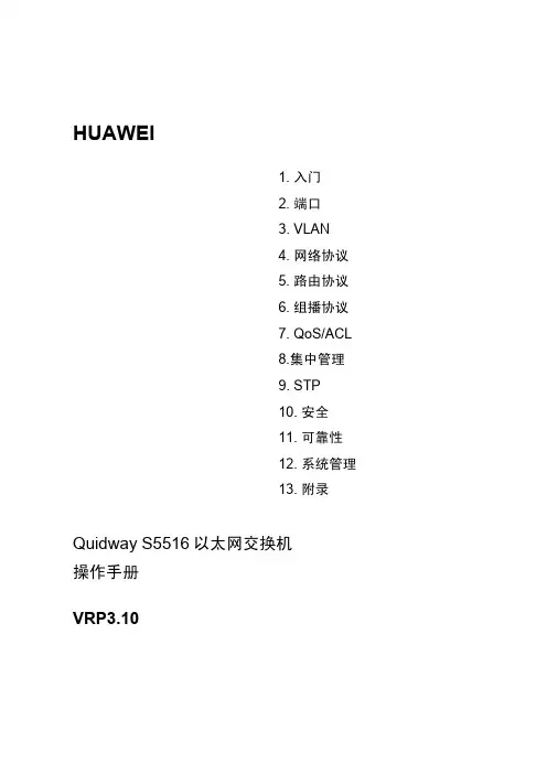
HUAWEI1. 入门2. 端口3. VLAN4. 网络协议5. 路由协议6. 组播协议7. QoS/ACL8.集中管理9. STP10. 安全11. 可靠性12. 系统管理13. 附录Quidway S5516以太网交换机操作手册VRP3.10Quidway S5516以太网交换机操作手册资料版本: T1-081694-20060930-C-1.04产品版本: VRP3.10BOM 编码: 31160994华为技术有限公司为客户提供全方位的技术支持。
通过华为技术有限公司代理商购买产品的用户,请直接与销售代理商联系。
直接向华为技术有限公司购买产品的用户,可与就近的华为办事处或用户服务中心联系,也可直接与公司总部联系。
华为技术有限公司地址:深圳市龙岗区坂田华为总部办公楼邮编:518129网址:声明Copyright ©2006华为技术有限公司版权所有,保留一切权利。
非经本公司书面许可,任何单位和个人不得擅自摘抄、复制本书内容的部分或全部,并不得以任何形式传播。
®、HUAWEI®、华为®、C&C08®、EAST8000®、HONET®、®、视点®、ViewPoint®、INtess®、ETS®、DMC®、TELLIN®、InfoLink®、Netkey®、Quidway®、SYNLOCK®、Radium®、雷霆®、M900/M1800®、TELESIGHT®、Quidview®、Musa®、视点通®、Airbridge®、Tellwin®、Inmedia®、VRP®、DOPRA®、iTELLIN®、HUAWEI OptiX®、C&C08iNET®、NETENGINE™、OptiX™、iSite™、U-SYS™、iMUSE™、OpenEye™、Lansway™、SmartAX™、边际网™、infoX™、TopEng™均为华为技术有限公司的商标。
Tel: ************/83E-mail:***********.cn 机架安装式16口工业以太网管理型交换机产品亮点:• 两个插槽,最多16个端口,可选RJ45、光纤、千兆及POE模块• 1U 19”半长机架安装,金属外壳,端口可选前置或后置• 容易配置的管理特性,包括SNMP, VLAN, QoS, IGMP, Radius/802.1x及路由选项• RSTP,支持快速、灵活的冗余• 坚固性设计,-20 ~ 70°C工作温度• 符合网络设备构建系统NEBS 3与欧洲电信标准协会ETSI标准,适用于严格应用场合• 符合美国电气制造商协会NEMA-TS2标准,特别适用于交通控制系统• 符合美国电气及电子工程师学会IEEE 1613和国际电工委员会IEC61850电源等级概述:SIXNET RK16是真正的工业以太网交换机,可提供包括千兆、光纤端口和POE选项的16个端口。
采用坚固的1U 19”半长机架安装,节省费用和空间。
RK16具有两个灵活的插槽,可选择10/100 RJ45端口,10、100或1000 Mbps光纤端口,或 10/100/1000 Mbps千兆RJ45端口以及POE模块,光纤端口有支持70+km长距离型。
RK16具有网络管理、网络优化级网络安全等最先进的软件特性。
特性:坚固灵活的硬件• 最多16个端口,符合IEEE 802.3标准• 2个灵活的插槽,可选电口、光口、千兆及POE模块• 节省空间的1U 19”半长机架安装金属外壳• 方便的前面板或后面板安装端口• 可选冗余电源输入• 可选两路报警输出继电器实时安全特性• 支持快速生成树协议(RSTP),构建快速冗余环• 支持SNMP v1,v2协议,实现网络管理• 支持SNMP v3协议,确保网络安全性• 支持SNMP通知(traps),及时报告报警及事件• 支持优先级划分(Qos/Cos/Tos/DiffServ),确保实时性• 支持IGMP(v1&v2)多播过滤(snooping & querying)• 支持VLAN,以便隔离网络通信Tel: ************/83E-mail:***********.cn • 支持链路汇聚(trunking),倍增网络带宽• 支持广播与多播风暴保护• 支持RMON及端口镜像,高级诊断特性• 真正的安全性,支持HTTPS, SNMPv3, Radius/802.1x等真正的工业设计,长期可靠性• -20 ~ +70 °C 工作温度,可选更宽温度范围• 免费固件升级• 符合NEBS Layer 3及ETSI,满足严格要求应用• 符合NEMA-TS2,适用于交通控制系统• 符合IEEE 1613 & IEC61850• 符合UL, CUL (CSA), CE 及FCC技术规格:一般性规格工作存储转发,线速交换,无阻塞模式所有端口支持全双工或半双工,及流量控制MAC地址4096转发及过滤速率 6.0 Mpps典型延迟时间 5 us,100 Mbps;16 us,10 Mbps以太网隔离1500 Vrms 1 minute配置端口RS232 (DB9)RJ45电端口RJ45口最多16个RJ45口,完全符合IEEE 802.3RJ45口速率和双工可配置,支持全双工和半双工,自动协商速率,10/100及10/100/1000(千兆端口)RJ45 MDI/MDIX自动mdi/mdix切换,自动支持直连和交叉线以太网供电(POE)最多8 POE端口(每单元一个POE模块),48 VDC, 125 VDC及交流单元光纤端口光纤端口可选10, 100, 1000 Mbps,距离可达70 km收发器可选SC, ST, MTRJ 及 LC 型连接器ST多模10BASE-FL 典型2+km; 850nm;使用50-62.5/125um光纤> 发送功率(dB): -19.5 min, -15 max> 接收灵敏度(dB): -31 typTel: ************/83 E-mail:***********.cnST多模SC100BASE-FX 典型2+km; 1310 nm; 使用50-62.5/125um光纤> 发送功率(dB): -23.5 min, -20 max> 接收灵敏度(dB): -31 maxMTRJ多模100BASE-FX 典型2+ km; 1310 nm; 使用50-62.5/125um光纤> 发送功率(dB): -23.5 min, -20 max> 接收灵敏度(dB): -31 maxLC多模100BASE-FX 典型2+ km; 1310 nm; 使用50-62.5/125um光纤> 发送功率(dB): -19 typ> 接收灵敏度(dB): -31 maxSC多模1000BASE-SX 典型550+ m; 850 nm; 使用50-62.5/125um 光纤> 发送功率(dB): -9.5 typ> 接收灵敏度(dB): -17 maxSC单模100BASE-FX 典型18+ km; 1310 nm; 使用9/125 um 光纤> 发送功率(dB): -15 typ> 接收灵敏度(dB): -31 maxLC单模100BASE-FX 典型15+ km; 1310 nm; 使用9/125 um 光纤> 发送功率(dB): -15 typ> 接收灵敏度(dB): -28 maxSC单模长距100BASE-FX 典型40+ km; 1310 nm; 使用9/125 um 光纤> 发送功率(dB): -5 typ> 接收灵敏度(dB): -34 maxSC单模1000BASE-LX 典型10+ km; 1310 nm; 使用9/125 um 光纤> 发送功率(dB): -9.5 typ> 接收灵敏度(dB): -20 maxSC单模长距1000BASE-LX 典型25+ km; 1310 nm; 使用9/125 um 光纤> 发送功率(dB): -4 typ> 接收灵敏度(dB): -21 maxSC单模长距1000BASE-ZX 典型40+ km; 1550 nm; 使用9/125 um 光纤> 发送功率(dB): -4 typ> 接收灵敏度(dB): -21 maxSC单模长距1000BASE-ZX 典型70+ km; 1550 nm; 使用9/125 um 光纤> 发送功率(dB): -3 typ> 接收灵敏度(dB): -23 max其它收发器请联系SIXNET网络管理支持的设备所有符合IEEE 802.3标准的设备协议SNMPv1/v2/v3, RMON, DHCP, SNTP, TFTP, STP, RSTP,QoS/CoS/ToS/DS, IGMPv1/v2, VLAN (tag and port based),HTTP, HTTPS (SSL & TSL), Telnet, Radius/802.1x等等Tel: ************/83E-mail:***********.cn 支持的工业协议Modbus/TCP, EtherNet/IP, PROFInet, FF HSE等等标准IEEE 802.3, 802.3u, 802.3x, 802.1D/w, 802.1p, 802.1Q,802.3z, 802.3ab, 802.3ad管理接口Web, 文本(Telent), CLI (命令行接口) 及SNMP电源和报警输出电源输入冗余电源输入选项(对于DC输入方式)输入电压范围100~240 VAC, 47-63 Hz.18~36 VDC,或-36 ~ -70 VDC,或88~150VDC功耗全部电口30 W;具有两个光口时50 W工业浪涌和冲击保护15 kW 尖峰, 5 kW (10次,每次10 us)报警输出选项1路Form C常闭触点,用于电源与软件状态报警环境工作温度-20 ~ 70°C (短期-40 ~ 85°C,符合IEC 60068)储存温度-40 ~ 85°C湿度 5 ~ 95% RH (不结露) (可选电路板涂层保护)振动NEBS (GR-63-CORE)冲击NEBS (GR-63-CORE)自由落体NEBS (GR-63-CORE)海拔高度-200 ~ 13000 ft. (-60 ~ 4000 m)标准和认证电气安全性UL60950, CUL (CSA) CEEMC FCC part 15, ICES-003, CE, NEBS(GR-1089-CORE)电源部分IEEE 1613 and IEC 61850 Class C rated交通控制系统NEMA TS2 rated网络设备构建系统NEBS Level 3 (GR-63 & GE-1089)欧洲电信标准协会ETSI compliantRoHS / WEEE RoHS (Pb free) / WEEE compliant ...ISO9001:2000Certified "Total Quality" company ...工业保证3年,需注册机械外壳1U 19" 半长机架金属粉末涂层钢防护IP30 粉尘防护安装19"机架安装(可选19" 托架,23"及ETSI机架安装组件)尺寸 1.8" x 8.8" x 10" (4.4 cm x 22.2 cm x 25.4 cm)重量 4 lbs (1.8 kg)Tel: ************/83E-mail:***********.cn 图片:端口前置面板端口后置面板。
目录第1章 IP地址配置.................................................................................................................1-11.1 IP地址简介........................................................................................................................1-11.1.1 IP地址的分类和表示...............................................................................................1-11.1.2 子网和掩码..............................................................................................................1-21.2 IP地址配置........................................................................................................................1-31.2.1 配置主机名和对应的IP地址....................................................................................1-31.2.2 配置VLAN接口的IP地址.......................................................................................1-41.3 IP地址的显示和调试..........................................................................................................1-41.4 IP地址配置举例.................................................................................................................1-51.5 IP地址配置排错.................................................................................................................1-5第2章 ARP配置....................................................................................................................2-12.1 ARP简介............................................................................................................................2-12.2 ARP配置............................................................................................................................2-22.2.1 手工添加/删除静态ARP映射项..............................................................................2-22.2.2 配置动态ARP老化定时器的时间............................................................................2-22.3 ARP的显示和调试.............................................................................................................2-3第3章 DHCP Relay配置........................................................................................................3-13.1 DHCP Relay简介...............................................................................................................3-13.2 DHCP Relay配置...............................................................................................................3-23.2.1配置DHCP Server的IP地址.................................................................................3-23.2.2配置VLAN接口对应的DHCP Server组................................................................3-33.2.3 配置DHCP Server组的用户地址表项.....................................................................3-33.2.4 使能/禁止VLAN接口上的DHCP安全特性.............................................................3-33.2.5 使能/禁止伪DHCP服务器检测功能........................................................................3-43.3 DHCP Relay显示和调试....................................................................................................3-43.4 DHCP Relay配置示例.......................................................................................................3-53.5 DHCP Relay配置排错.......................................................................................................3-6第4章 IP性能配置.................................................................................................................4-14.1 IP性能配置........................................................................................................................4-14.1.1 配置TCP属性.........................................................................................................4-14.1.2 配置特殊IP报文是否送CPU..................................................................................4-24.1.3 配置是否转发三层广播报文.....................................................................................4-24.2 IP性能显示和调试..............................................................................................................4-34.3 IP性能配置排错.................................................................................................................4-4第1章 IP地址配置1.1 IP地址简介1.1.1 IP地址的分类和表示IP地址是分配给连接在Internet上的设备的一个32比特长度的地址。
端口配置目录目录第1章以太网端口配置........................................................................................................1-11.1 以太网端口简介.........................................................................................................1-11.2 以太网端口配置.........................................................................................................1-21.2.1 以太网端口配置任务列表..................................................................................1-21.2.2 进入/退出以太网端口配置模式...........................................................................1-21.2.3 关闭/打开以太网端口.......................................................................................1-31.2.4 设置以太网端口的描述字符串............................................................................1-31.2.5 设置以太网端口的双工状态..............................................................................1-31.2.6 设置以太网端口的速率.....................................................................................1-41.2.7 设置以太网端口连接的网线类型........................................................................1-51.2.8 设置以太网端口的流量控制...............................................................................1-51.2.9 禁止/允许长帧通过以太网端口...........................................................................1-51.2.10 禁止/允许以太网端口进行MAC地址学习.........................................................1-61.2.11 设置以太网端口的链路环回检测功能................................................................1-61.2.12 设置以太网端口的优先级................................................................................1-71.2.13 将以太网端口设置为Trunk端口.....................................................................1-71.2.14 设置Trunk端口的属性...................................................................................1-81.2.15 指定以太网端口所属的VLAN..........................................................................1-81.3 以太网端口的监控与维护............................................................................................1-91.4 以太网端口配置举例.................................................................................................1-101.4.1 配置Trunk端口的PVID......................................................1-101.5 以太网端口配置排错.................................................................................................1-11第2章以太网端口汇聚配置.................................................................................................2-12.1 以太网端口汇聚简介...................................................................................................2-12.2 以太网端口汇聚配置...................................................................................................2-12.2.1 以太网端口汇聚配置任务列表............................................................................2-12.2.2 将一组以太网端口设置为同一个汇聚组的成员....................................................2-12.3 以太网端口汇聚的监控与维护.....................................................................................2-22.4 以太网端口汇聚典型配置举例.....................................................................................2-22.4.1 配置参与汇聚的以太网端口...............................................................................2-22.5 以太网端口汇聚故障的诊断与排除...............................................................................2-3第1章以太网端口配置1.1 以太网端口简介S5516以太网交换机在后面板上提供1个固定的10Base-T以太网接口在前面板上提供4个千兆扩展模块插槽满配置情况下S5516以太网交换机支持的以太网端口特性如下可以与升级软件所在的网络设备协商确定双工工作方式l1000Base-LX/SX以太网端口工作在千兆全双工模式下1000Base-SX 模块可以为用户提供4个千兆多模光端口可以工作在半双工自协商模式下作为升级软件用的10Mbit/s以太网端口不可配置下面一起来介绍1.2 以太网端口配置1.2.1 以太网端口配置任务列表要配置以太网端口的相关特性参数然后对相关参数进行配置l进入/退出以太网端口配置模式l关闭/打开以太网端口l设置以太网端口的描述字符串l设置以太网端口的双工状态l设置以太网端口的速率l设置以太网端口连接的网线类型l设置以太网端口的流量控制l禁止/允许长帧通过以太网端口l禁止/允许以太网端口进行MAC地址学习l设置以太网端口的链路环回检测功能l设置以太网端口的优先级l将以太网端口设置为Trunk端口l设置Trunk端口的属性l指定以太网端口所属的VLAN1.2.2 进入/退出以太网端口配置模式要对以太网端口进行配置也可以通过退出命令回到全局配置模式表1-1 进入以太网端口配置模式操作命令进入以太网端口配置模式interface interface_type interface_number请在以太网端口配置模式下进行下列配置表1-2 退出当前所在的以太网端口操作命令退出当前所在的以太网端口exit1.2.3 关闭/打开以太网端口可以指定关闭/打开当前的以太网端口表1-3 关闭/打开以太网端口操作命令关闭以太网端口shutdown打开以太网端口no shutdown这一对命令一般用于重新启动以太网端口通过先关闭端口再将其打开的方法这在某些情况需要使其生效缺省情况下1.2.4 设置以太网端口的描述字符串可以对以太网端口设置必要的描述请在以太网端口配置模式下进行下列配置端口的描述字符串为空全双工进行设置请在以太网端口配置模式下进行下列配置1000Base-LX/SX千兆以太网端口只能工作在全双工模式下全双工自协商缺省情况下自协商即自动与对端协商确定是工作在全双工状态还是工作在半双工状态一般强制双方的端口都工作在全双工状态1000Base-T以太网端口则能够支持10Mbit/s1000Mbit/s三种速率请在以太网端口配置模式下进行下列配置1000Base-LX/SX以太网端口只支持1000Mbit/s这一种速率10Mbit/s100Mbit/s缺省情况下1.2.7 设置以太网端口连接的网线类型1000Base-T以太网端口可以连接普通或交叉这两种类型的五类双绞线请在以太网端口配置模式下进行下列配置端口的网线类型为autoÐÍ1.2.8 设置以太网端口的流量控制可以通过下面的命令启动或关闭以太网端口的流量控制功能表1-8 设置以太网端口的流量控制操作命令启动以太网端口的流量控制flow-control关闭以太网端口的流量控制no flow-control缺省情况下1.2.9 禁止/允许长帧通过以太网端口在进行文件传输等大吞吐量数据交换的时候1518字节可以通过该命令请在以太网端口配置模式下进行下列配置表1-9 禁止/允许长帧通过以太网端口操作命令禁止长帧通过以太网端口jumboframe disable允许长帧通过以太网端口no jumboframe disable缺省情况下1.2.10 禁止/允许以太网端口进行MAC地址学习以太网端口可以进行MAC地址学习再收到以此地址为目的地址的数据报文时不会对其进行广播转发例如潜在的攻击者可能使用不同源地址的以太网帧来攻击交换机此时请在以太网端口配置模式下进行下列配置允许以太网端口进行MAC地址学习环回检测分为两种对内自环适用于检测本端口配合检查对端以及连接线路的物理状况只有在做测试时请在以太网端口配置模式下进行下列配置表1-11 设置以太网端口的链路环回检测功能操作命令指定以太网端口进行对内自环检测loopback internal指定以太网端口允许进行对外回波检测loopback external禁止以太网端口进行链路环回检测no loopback缺省情况下1.2.12 设置以太网端口的优先级可以通过下面的命令设置某个以太网端口的优先级表1-12 设置以太网端口的优先级操作命令设置以太网端口的优先级priority priority将以太网端口的优先级恢复为缺省值no priority缺省情况下1.2.13 将以太网端口设置为Trunk端口在与VLAN有关的配置中顾名思义TrunkËüÔÊÐíÖ¸¶¨µÄÒ»¸ö»ò¶à¸öVLAN的帧通过它只允许其所属VLAN的帧通过请在以太网端口配置模式下进行下列设置所有的以太网端口均为Access端口1.2.14 设置Trunk端口的属性将一个以太网端口指定为Trunk端口以后当指定允许通过的VLAN后而指定缺省的VLAN ID VLAN帧的发送和接收遵循IEEE 802.1Q标准表1-14 设置Trunk端口的属性操作命令指定Trunk端口允许通过的VLAN switchport trunk allowed vlan { vlan_list | all }取消对Trunk端口允许通过VLAN的指定no switchport trunk allowed vlan { vlan_list | all }设置Trunk端口的缺省VLAN ID switchport trunk native vlan vlan_id 将Trunk端口的缺省VLAN ID恢复为缺省值no switchport trunk native缺省情况下除了VLAN 1之外不允许其它任何VLAN的帧通过该设置只对Trunk端口有效此命令使用的条件是即Access端口所指定的VLAN 不是缺省VLAN并且必须已经存在表1-15 指定以太网端口所属的VLAN操作命令指定以太网端口所属的VLAN switchport access vlan vlan-id把以太网端口从指定VLAN中删除no switchport access vlan vlan-id缺省情况下后配置的归属关系将会覆盖原有的归属关系包括端口类型是否双工流控这些信息对于监控和维护以太网端口是有用处的使用clear命令可以清除以太网端口的统计信息其中表1-16 显示以太网端口的信息操作命令清除端口的统计信息clear interface[ interface_type [ interface_number ] ]显示端口的所有信息show interface [ interface_type [ interface_number ] ]Quidway# show interface gigabitethernet 1/1GigabitEthernet1/1 is upHardware is Gigabit Ethernet, Hardware address is 00e0.fc00.5516Auto-duplex, Auto-speed, 1000_BASE_TFlow control is enableAllow jumbo frame to passPVID is 11Priority is 0Description: S5516 GigaEth 2/1Mdi type: autoLoopback: internalIt is a vlan trunking port, vlan(s) passing this port:1(default vlan)vlan(s) allowed to pass this port:1(default vlan), 2-3, 6-10It is not a monitor portIt doesn't belong to a port-aggregation0 packets output0 bytes, 0 multicasts, 0 broadcasts, 0 pauses0 packets input0 bytes, 0 multicasts, 0 broadcasts, 0 pauses0 FCS errors0 long frames1.4 以太网端口配置举例1.4.1 配置Trunk端口的PVID1. 组网需求S5516系列以太网交换机与对端交换机使用Trunk端口GigabitEthernet 1/4相连PVID即缺省VLAN IDµ±ÒÔÌ«ÍøÖ¡·¢Ë͹ý³ÌÖгö´í¿ÉÒÔ½«PVID作为标签打上Quidway(config)# interface gigabitethernet 1/4²¢ÔÊÐí27到50ÕâЩVLAN最好已创建Quidway(config-if-GigabitEthernet1/4)# switchport trunk allowed vlan 2 6 7to 50 120Quidway(config-if-GigabitEthernet1/4)# exit创建VLAN 100设置端口GigabitEthernet 1/4的PVID为100Quidway(config-vlan100)# interface gigabitethernet 1/4Quidway(config-if-GigabitEthernet1/4)# switchport trunk native vlan 100Quidway(config-if- GigabitEthernet1/4)# show interface GigabitEthernet 1/4GigabitEthernet1/4 is upHardware is Gigabit Ethernet, Hardware address is 00e0.fc00.0010Auto-duplex, Auto-speed, 1000_BASE_TAllow jumbo frame to passFlow control is disablePVID is 100Priority is 0Mdi type: autoIt is a vlan trunking port, vlan(s) passing this port:1(default vlan), 2, 6-50, 120vlan(s) allowed to pass this port:1(default vlan), 2, 6-50, 120It is not a monitor portIt doesn't belong to a port-aggregation28 packets output3366 bytes, 0 multicast, 1 broadcasts, 0 pause701 packets input148879 bytes, 235 multicast, 425 broadcasts, 0 pause0 FCS errors0 long frames1.5 以太网端口配置排错故障现象故障排除l首先使用show interface命令检查该端口是否为Trunk端口则应先将其配置成Trunk端口则转下一步最好先创建该VLANÈçûÓд´½¨¸ÃVLAN然后再转而配置端口的PVID第2章以太网端口汇聚配置2.1 以太网端口汇聚简介链路汇聚是指将多个以太网链路汇聚在一起形成一个汇聚组从外面看起来在S5516中即最多可将16个端口汇聚到一起参与汇聚组的端口的起始值可以为任意一个可用的以太网端口除了编号最小的端口且一台S5516交换机可以支持多个千兆以太网汇聚组同一汇聚组内的以太网端口号必须连续如果组内的端口是同一槽内的端口如果组内的端口跨越了两个槽槽号必须连续l将一组以太网端口设置为同一个汇聚组的成员2.2.2 将一组以太网端口设置为同一个汇聚组的成员该配置任务用来将一组以太网端口汇聚到一起请在全局配置模式下进行下列配置2.3 以太网端口汇聚的监控与维护使用以下命令可以查看参与汇聚的端口的相关信息其他成员端口名和各端口的模式等表2-2 显示参与汇聚的以太网端口的信息操作命令显示参与汇聚的以太网端口的信息show link-aggregation [ GigabitEthernet master_interface_number ]Quidway# show link-aggregation gigabitethernet1/1Master port: GigabitEthernet1/1Other sub-ports:GigabitEthernet1/2GigabitEthernet1/3GigabitEthernet1/4GigabitEthernet2/1GigabitEthernet2/2GigabitEthernet2/3GigabitEthernet2/4Mode: ingress-egress2.4 以太网端口汇聚典型配置举例2.4.1 配置参与汇聚的以太网端口1. 组网需求本例将验证端口汇聚命令的使用以实现出/入负荷在各成员端口中进行分担因为Trunk端口上允许多个VLAN通过需要将流量在各个端口中进行分担用2个端口汇聚接入S30262. 组网图图2-1 配置汇聚以太网端口示例图3. 配置步骤配置S5516将以太网端口GigabitEthernet1/1至GigabitEthernet1/2汇聚到一起显示该汇聚端口的信息配置端口汇聚不成功可以按照如下步骤进行请检查所输入的参数中以太网端口的起始值是否小于终结值则转下一步请检查所输入的端口号起始/终结值所涵盖范围内的以太网端口是否都不是已有的汇聚组的成员则转下一步请检查参与汇聚的端口的总数目是否小于或等于16个l如果以上检查都正确。
组播协议配置目录目录第1章 GMRP配置.............................................................................................................1-11.1 GMRP协议简介.........................................................................................................1-11.2 GMRP配置...............................................................................................................1-11.2.1 GMRP配置任务列表........................................................................................1-11.2.2 启动/关闭全局GMRP......................................................................................1-11.2.3 启动/关闭端口GMRP......................................................................................1-21.3 GMRP的监控与维护..................................................................................................1-21.4 GMRP典型配置举例..................................................................................................1-3第2章 IGMP Snooping配置...............................................................................................2-12.1 IGMP Snooping简介..................................................................................................2-12.2 IGMP Snooping配置..................................................................................................2-32.2.1 IGMP Snooping的配置任务列表.......................................................................2-32.2.2 启动/关闭IGMP Snooping...............................................................................2-42.2.3 设置路由器端口老化时间..................................................................................2-42.2.4 设置响应查询最晚时间.....................................................................................2-52.2.5 设置多播组端口成员老化时间...........................................................................2-52.3 IGMP Snooping的监控与维护....................................................................................2-52.4 IGMP Snooping典型配置举例....................................................................................2-72.4.1 启动IGMP Snooping.......................................................................................2-72.5 IGMP Snooping故障诊断与排错.................................................................................2-8第1章 GMRP配置1.1 GMRP协议简介GMRP GARP多播注册协议Generic Attribute Registration Protocol的一种应用维护交换机中的动态组播注册信息并动态更新本地的组播注册信息以便使同一交换网内所有支持GMRP特性的设备的组播信息达成一致也包括由其他交换机动态注册到本地交换机的组播注册信息必须先启动全局GMRPGMRP的主要配置任务列表如下表1-1 启动/关闭全局GMRP操作命令启动全局GMRP gmrp关闭全局GMRP no gmrp缺省情况下1.2.3 启动/关闭端口GMRP在启动端口GMRP之前请在千兆以太网端口配置模式下进行下列配置不启动端口GMRPÆäÖÐ表1-3 GMRP的监控与维护操作命令显示GMRP的统计信息show gmrp statistics [ ports_list ]显示GMRP的全局状态信息show gmrp status打开GMRP的事件/报文调试开关debug gmrp { event | packet }关闭GMRP的事件/报文调试开关no debug gmrp { event | packet }(1) 显示GMRP的统计信息Quidway# show gmrp statisticsGMRP statistics on port GigabitEthernet1/1Gmrp StatusGmrp Last Pdu OriginǧÕ×ÒÔÌ«Íø¶Ë¿ÚGigabitEthernet 1/1的GMRP为开启状态最后的GMRP数据单元来源为0000.0000.0000È«¾ÖGMRP已经处于启动状态1.4 GMRP典型配置举例1. 组网需求为了实现交换机之间组播信息的动态注册和更新2. 组网图S5516 AS5516 B图1-1 GMRP示例组网图3. 配置步骤配置S5516 A启动全局GMRP在千兆以太网端口GigabitEthernet 2/1上启动端口GMRPQuidway(config)# gmrpQuidway(config)# interface gigabitethernet 4/1Quidway(config-if-GigabitEthernet4/1)# gmrp第2章 IGMP Snooping配置2.1 IGMP Snooping简介1. 原理IGMP Snooping和IGMP Internet组管理协议它们使用的都是相同的报文IGMP运行在网络层当第二层设备收到主机和路由器之间传递的IGMP报文时再由IGMP Snooping分析IGMP报文所带的信息以后从路由器下发的多播报文就根据MAC多播地址表进行转发而且都是IGMP特定组查询报文它不会向端口发任何报文如下图所示图2-1 未实现IGMP Snooping时多播报文的传播过程示意图当应用IGMP Snooping后如下图交换机路由器主机主机Internet图2-2 实现IGMP Snooping 时多播报文的传播过程示意图2. 实现实现IGMP Snooping 的示意图IGMPSnoopingIGMPIGMP图2-3 实现IGMP Snooping 示意图IGMP Snooping 对收到的IGMP 报文作以下处理l IGMP通用查询报文如果是旧路由器端口如果是新端口同时启动对新路由器端口的老化定时器路由器端口老化时间和响应查询最晚时间都可手工配置只向被查询的IP多播组发特定组查询l IGMP报告报文则会新建MAC多播组,并将所有路由器端口下发到此MAC多播组在芯片中的MAC多播转发表中则只新建IP多播组如果报告的MAC多播组存在并且该端口属于该MAC多播组不管在何种情况下收到IGMP报告报文此时间可手工配置当IGMP Snooping收到某端口对某IP多播组的离开报文以确认此端口还有没有此组的其他成员3. 特性l可动态指定路由器端口l可通过命令行启动/关闭IGMP Snooping的运行但命令行的操作与IGMP Snooping是否启动无关l当IGMP Snooping出现问题2.2 IGMP Snooping配置2.2.1 IGMP Snooping的配置任务列表对IGMP Snooping的配置命令没有先后顺序的要求l启动/关闭IGMP Snoopingl设置路由器端口老化时间l设置响应查询最晚时间l设置多播组端口成员老化时间2.2.2 启动/关闭IGMP Snooping为了控制IGMP Snoopng是否在二层建立和维护MAC多播转发表请在全局配置模式下进行下列配置但在GMRP运行时将无法启动IGMP Snooping¿ÉÒÔÔÚÆô¶¯I GMP Snooping之前在特权用户模式下使用命令show gmrp status来查看GMRP是否正在运行IGMP Snooping处于启动状态即指交换机上行与运行IGMP的路由器相连的端口如果在该时间之内没有收到路由器发来的通用查询报文请在全局配置模式下进行下列配置路由器端口老化时间为260秒2.2.4 设置响应查询最晚时间设置响应查询最晚时间的目的是就把该端口从多播组端口成员中删去表2-3 设置响应查询最晚时间操作命令设置响应查询最晚时间igmp-snooping max-response-time seconds将响应查询最晚时间恢复为缺省值no Igmp-snooping max-response-time缺省情况下2.2.5 设置多播组端口成员老化时间设置多播组端口成员老化时间的目的是则向这些端口的对端发送查询报文表2-4 设置多播组端口成员老化时间操作命令设置多播组端口成员老化时间igmp-snooping host-aging-time secondsno igmp-snooping host-aging-time将多播组端口成员老化时间恢复为缺省值缺省情况下2.3 IGMP Snooping的监控与维护请在特权用户模式或全局配置模式下进行下列操作show系列命令还可以在除普通用户模式以外的所有其它模式下使用全局配置模式操作命令显示IGMP Snooping的统计信息show igmp-snooping statistics显示VLAN下的IP多播组和MAC多播show igmp-snooping group [ vlan vlanid ]组信息打开IGMP Snooping的调试开关debug igmp-snooping { all | abnormal |groups | packets | timers }关闭IGMP Snooping的调试开关no debug igmp-snooping { all | abnormal| groups | packets | timers }(1) show igmp-snooping configuration命令将显示IGMP Snooping的所有配置信息Quidway# show igmp-snooping configurationEnable IGMP-Snooping.The router port timeout is 300 second(s).The max response timeout is 30 second(s).The member port timeout is 300 second(s).上述信息表示路由器端口老化时间为300秒多播组端口成员老化时间为300秒此命令在IGMP Snooping没有按预期建立MAC 多播组时对诊断IGMP Snooping很有用处l IGMP Snooping收到一个IGMP 通用查询报文l IGMP Snooping收到零个IGMP 版本1的报告报文l IGMP Snooping收到零个IGMP离开报文l IGMP Snooping发送零个IGMP特定组查询报文&说明而是将路由器端口单独列出并显示在所有本VLAN下的多播组前面Quidway# show igmp-snooping group vlan 2***************Multicast group table***************Vlan(id):2.Router port(s):GigabitEthernet4/1IP group(s):the following ip group(s) match to one mac group.IP group address:230.45.45.1Member port(s):Ethernet1/1MAC group(s):MAC group address:01-00-5e-2d-2d-01Member port(s):Ethernet1/1上述信息表示l路由器端口是GigabitEthernet 4/1l IP多播组成员是GigabitEthernet 1/1l MAC多播组成员是GigabitEthernet 1/1交换机的路由器端口与路由器相连2.组网图交换机路由器主机主机Internet图2-4 配置IGMP Snooping 组网图3. 配置步骤Quidway# show gmrp statusÏÔʾIGMP Snooping 当前的状态当IGMP Snooping 没有启动时Quidway(config)# igmp-snooping enable2.5 IGMP Snooping 故障诊断与排错故障现象原因分析1¹ÊÕÏÅųý1l 如果IGMP Snooping 没有启动l如果排除了原因1原因分析2¹ÊÕÏÅųý2show igmp-snooping group或show igmp-snooping group [ vlan vlanid ]查看多播组是否是所预期的则向IGMP Snooping 开发或维护人员求助则进入原因分析3底层建立的多播转发表不对l在特权模式下打开IGMP Snooping的组开关show igmp-snooping group或show igmp-snooping [ vlan vlanid]查看底层的MAC多播转发表和IGMP Snooping的MAC多播转发表是否一致可以在特权用户模式下使用命令show mac vlan显示底层在vlanid下所建立的MAC多播转发表是否和IGMP Snooping建立的MAC多播转发表一致。
端口目录目录第1章以太网端口配置...........................................................................................................1-11.1 以太网端口简介..................................................................................................................1-11.2 以太网端口配置..................................................................................................................1-11.2.1 进入以太网端口视图................................................................................................1-21.2.2 打开/关闭以太网端口...............................................................................................1-21.2.3 对以太网端口进行描述............................................................................................1-21.2.4 设置以太网端口双工状态........................................................................................1-31.2.5 设置以太网端口速率................................................................................................1-31.2.6 设置以太网端口网线类型.........................................................................................1-41.2.7 设置以太网端口流量控制.........................................................................................1-41.2.8 允许/禁止长帧通过以太网端口................................................................................1-51.2.9 设置以太网端口的链路类型.....................................................................................1-51.2.10 把当前以太网端口加入到指定VLAN.....................................................................1-61.2.11 设置以太网端口缺省VLAN ID..............................................................................1-71.2.12 设置端口的VLAN VPN特性.................................................................................1-71.2.13 设置以太网端口环回监测功能...............................................................................1-81.3 以太网端口显示和调试......................................................................................................1-91.4 以太网端口配置举例..........................................................................................................1-91.5 以太网端口排错................................................................................................................1-10第2章以太网端口汇聚配置....................................................................................................2-12.1 以太网端口汇聚简介..........................................................................................................2-12.2 以太网端口汇聚配置..........................................................................................................2-12.2.1 将一组以太网端口设置为汇聚端口..........................................................................2-12.3 以太网端口汇聚显示和调试................................................................................................2-22.4 以太网端口汇聚配置举例...................................................................................................2-22.5 以太网端口汇聚配置排错...................................................................................................2-3第1章以太网端口配置1.1 以太网端口简介S5516以太网交换机提供4个千兆扩展模块插槽,用户可根据自己的实际情况,选配如下模块:4端口1000Base-SX模块、4端口1000Base-LX模块、4端口10/100/1000Base-T模块、4端口1000Base-X SFP模块、4端口堆叠模块。
EncendidoApagadoIndicador de alimentaciónActividad(intermitente)Sin conexión (apagado)EnlaceIndicadores de L/A puertosIndicadores de 100M puertos100 Mbps10 Mbps (apagado)Router opcionalEquipo ServidorMódemopcionalInternetConmutador Ethernet de 16 puertos ProSafe JFS516Paso 2. Conectar la alimentación Paso 3. Comprobar el estado Paso 1. Conectar el equipoJFS516Guía de instalaciónSeptiembre de 2012Este símbolo se ha colocado conforme a la directiva 2002/96 de la UE sobre Residuos de Aparatos Eléctricos y Electrónicos (la Directiva RAEE). Si se tuviera que desechar este producto dentro de la Unión Europea, se tratará y se reciclará de conformidad con lo dispuesto en las leyes locales pertinentes, en aplicación de la directiva RAEE.NETGEAR, el logotipo de NETGEAR y Connect with Innovation son marcas comerciales o marcas comerciales registradas de NETGEAR, Inc. o sus filiales en Estados Unidos y otros países. La información contenida en el documento puede sufrir modificaciones sin previo aviso. El resto de marcas y nombres de productos son marcas comerciales o marcas comerciales registradas de sus respectivos titulares. © NETGEAR, Inc. Todos los derechos reservados.Sólo para uso en interior en todos los países de la UE y Suiza.Para la declaración de conformidad de la UE completa, visite /app/answers/detail/a_id/11621/.Condiciones : Con el fin de mejorar el diseño interno, el funcionamiento y la fiabilidad, NETGEAR se reserva el derecho de realizar modificaciones del producto descrito en el presente documento sin previo aviso. NETGEAR no asume responsabilidad alguna derivada del uso o la aplicación de los productos o circuitos descritos en el presente documento.EspecificacionesEspecificaciones DescripciónInterfaz de redConector RJ-45 para interfaz Ethernet 10BASE-T, o 100BASE-TXCable de red Cable Ethernet categoría 5 (Cat 5) o superior Puertos16AC (alimentación)100-240VAC 50-60Hz, 0,3A máx Consumo de energía 4.6W máx.Peso1,43Kg (3,15 libras)Dimensiones(anchura x profundidad x altura)330 mm x 169 mm x 43 mm 13 pulg. x 6,65 pulg. x 1,7 pulg.Temperatura de funcionamiento 0–40° C (32–104° F)Humedad de funcionamiento Humedad relativa 90%, no condensadaCumplimiento con las normas electromagnéticas CE Clase A, FCC Clase A, VCCI Clase A, C-Tick Clase A, CCCNormativas de seguridadMarca CE, comerciales listadas en UL (UL 60950-1), CB, CCCServicio técnicoUna vez instalado el dispositivo, busque el número de serie en la etiqueta del producto y regístrelo en https:// .Debe registrar su producto antes de poder usar el soporte telefónico de NETGEAR. NETGEAR recomienda registrar su producto en su sitio web NETGEAR. Para actualizaciones del producto y soporte web, visite .。
KLM5516 百兆16口非网管型导轨式工业级以太网交换机
●支持百兆16电口
●符合重工业 EN61000-6-2 标准
●10/100M ,全 / 半双工,MDI/MDI-X 自适应 ●坚固的金属外壳,IP40 防护等级
●支持DC12V 、24V 、48V 或AC/DC220V 电源输入 ●工业级宽温设计,无风扇设计
产品简述
KLM5516系列交换机可以用于即插即用的简单应用方式,满足用户的需求。
所有的电口支持自动协商、
Auto-MDI/MDI-X 等功能。
非网管型KLM5516 系列交换机提供冗余电源支持,可同时提供宽范围的直流和交流电源输入。
在结构安装方面该交换机是一款紧凑型交换机,占用空间小,使用卡轨安装。
技术参数
安装尺寸
订购型号。