Hydrothermal Synthesis
- 格式:pdf
- 大小:291.35 KB
- 文档页数:5
Handbook of Heterogeneous CatalysisContents:1 Introduction1.1 Principles of Heterogeneous Catalysis (James A. Dumesic)1.2 Development of the Science of Catalysis (Burtron H. Davis)1.3 Development of Industrial Catalysis (Uwe Dingerdissen)2 Preparation of Solid Catalysts2.1 Developing Industrial Catalysis (Ewald Gallei)2.2 Computer-Aided Strategies for Catalyst Development (Manfred Baerns)2.3 Bulk Catalysts and Supports2.3.1 Fused Catalysts (Robert Schlögl)2.3.2 Skeletal Metal Catalysts (Mark S. Wainwright)2.3.3 Precipitation and Co-precipitation (Ferdi Schüth)2.3.4 Sol-Gel Process (Miron V. Landau)2.3.5 Hydrothermal Zeolite Synthesis (Pierre A. Jacobs)2.3.6 Ordered Mesoporous Materials (Freddy Kleitz)2.3.7 Pillared Clays (José J. Fripiat)2.3.8 Metal Organic Frameworks (Ulrich Müller)2.3.9 Sulfated Zirconia and Related Materials (Friederieke Jentoft)2.3.10 Ion Exchange Resins (Bruce C. Gates)2.3.11 Flame Hydrolysis (Dieter Kerner)2.3.12 Solid-State Reactions (Bernard Delmon)2.3.13 Heteropoly Compounds (Makoto Misono)2.3.14 High-Surface Area Carbides, Nitrides and Phosphides (S. Ted Oyama)2.3.15 Carbons (Robert Schlögl)2.4 Supported Catalysts2.4.1 Deposition Precipitation (John W. Geus)2.4.2 Impregnation and Ion Exchange (Michel Che)2.4.3 Solid-State Ion Exchange in Zeolites ( Hellmut G. Karge)2.4.4 Metal Clusters in Zeolites (Wolfgang M. H. Sachtler)2.4.5 Anchoring and Grafting of Coordination Metal Complexes onto Oxide Surfaces (Michel Che) 2.4.6 Chemical Vapor Deposition and Related Techniques (Yasuhiro Iwasawa)2.4.7 Spreading and Wetting (Helmut Knözinger)2.4.8 Tribochemical Methods (Bernd Kubias)2.4.9 Immobilization of Molecular Catalysts (Reiner Anwander)2.4.10 Ship-in-the-Bottle Catalysts (Stefan Ernst)2.4.11 Supported Liquid Catalysts (Peter Wasserscheid)2.4.12 Immobilization of Biological Catalysts (Marion B. Ansorge-Schumacher)2.5 Formation of the Final Catalyst2.5.1 Reactions during Catalyst Activation (Bernard Delmon)2.5.2 Catalyst Forming (Ferdi Schüth)2.6 Standard Catalysts2.6.1 Non-Zeolitic Standard Catalysts (Geoffrey C. Bond)2.6.2 Zeolite Standard Catalysts (Michael Stöcker)3 Characterization of Solid Catalysts3.1 Physical Properties3.1.1 Surface Area and Porosity (Kenneth S. W. Sing)3.1.2 Particle Size and Dispersion Measurements (Pierre Gallezot)3.1.3 Structure and Morphology X-Ray Powder Diffraction (Daniel Herein)3.1.3.2 X-Ray Absorption Spectroscopy (Diek C. Koningsberger)3.1.3.3 Electron Microscopy and Diffraction (Sbhaya K. Datye)3.1.3.4 Scanning Probe Techniques (Flemming Besenbacher)3.1.3.5 Heterogeneous Catalysis and High Electric Fields (Norbert Kruse)3.1.3.6 Gamma Spectroscopy (J. W. Niemantsverdriet)3.1.3.7 Solid-State NMR Spectroscopy (Michael Hunger)3.1.3.8 Vibrational Spectroscopy (Helmut Knözinger)3.1.3.9 Neutron Scattering (Hervé Jobic)3.1.3.10 Morphological Characteristics (Friedrich Schmidt)3.1.4 Mechanical Properties (Friedrich Schmidt)3.2 Chemical Properties3.2.1 Bulk Chemical Composition (Peter Albers)3.2.2 Surface Chemical Composition (Edmund Taglauer)3.2.3 Valence States3.2.3.1 Photoelectron and Auger Electron Spectroscopy (Giuliano Moretti)3.2.3.2 UV/Vis and EPR Spectroscopy (Michel Che)3.2.3.3 Photoluminescence Spectroscopy (Masakazu Anpo)3.2.3.4 Muon Spin Resonance (Emil Roduner)3.2.3.5 Temperature-Programmed Reduction and Oxidation (Helmut Knözinger)3.2.4 Acidity and Basicity3.2.4.1 Concepts and Analysis of Surface Acidity and Basicity (Hellmut G. Karge)3.2.4.2 Thermochemical Characterization of Surface Acidity and Basicity (James A. Dumesic) 3.2.4.3 IR Spectroscopy for the Characterization of Surface Acidity and Basicity (Helmut Knözinger)3.2.4.4 NMR Spectroscopy for the Characterization of Surface Acidity and Basicity (Michael Hunger)3.2.5 Active Phase-Support Interactions3.2.5.1 Metal-Support Interactions (Bert M. Weckhuysen)3.2.5.2 Oxide-Oxide Interactions (Bert M. Weckhuysen)3.2.6 Carbonaceous Deposits (Peter Albers)3.3 IUPAC Recommandations3.3.1 Reporting Physisorption Data for Gas/Solid Systems3.3.2 Methods and Procedures for Catalyst Characterization (J. Haber, J. H. Block, B. Delmon)4 Model Systems4.1 Single-Crystal Surfaces (Gabor A. Somorjai)4.2 Supported Metal Clusters (Bruce C. Gates)4.3 Metallic Glasses (Alfons Baiker)4.4 Bimetallic Model Catalysts (José A. Rodriguez)4.5 Ultrathin Oxide Films (Hans-Joachim Freund)4.6 Oxide Model Systems (Hicham Idriss)4.7 Microcrystalline Oxides (Adriano Zecchina)4.8 Oxide Solid Solutions (Frank S. Stone)5 Elementary Steps and Mechanisms5.1 Chemisorption5.1.1 Principles of Chemisorption (Hans-Joachim Freund)5.1.2 Reactivity Index Relations in Theoretical Heterogeneous Catalysis (Rutger van Santen)5.2 Microkinetics5.2.1 Rates of Catalytic Reactions (James A. Dumesic)5.2.2 Dynamics of Surface Reactions (G. Ertl)5.2.3 Theoretical Modelling of Catalytic Reactions (Jens K. Nørskov)5.2.4 Non-linear Dynamics: Oscillatory Kinetics and Spatio-Temporal Pattern Formation (Gerhard Ertl)5.2.5 Isotopic Labeling and Kinetic Isotope Effects (Frank Bauer)5.2.6 Transient Catalytic Studies (Kai-Olaf Hinrichsen)5.3 Factors Influencing Catalytic Action5.3.1 Substituent Effects (Helmut Knözinger)5.3.2 Spillover Effects (Frank Rößner)5.3.3 Ensemble and Ligand Effects in Metal Catalysis (Wolfgang M. H. Sachtler)5.3.4 Promotors and Poisons (Bruce E. Koel)5.4 Hydrocarbon Reaction Mechanisms (Bruce C. Gates)5.5 Computer Simulations5.5.1 Computer Simulations of Structures and Reactivity (C. Richard A. Catlow)5.5.2 Molecular Simulation of Adsorption and Diffusion (Doros N. Theodorou)5.5.3 Computer Simulation of Shape Selectivity Effects (Berend Smit)6 Makrokinetics and Transport Processes6.1 Rate Procurement and Kinetic Modelling (Jacob A. Moulijn)6.2 Diffusion Coefficients in Porous Media (Jörg Kärger)6.3 Simultaneous Heat and Mass Transfer and Chemical Reaction (Gerhard Emig)6.4 NMR Tomography (Lynn Gladden)6.5 Positron Emitters in Catalysis Research (Gert Jonkers)6.6 Computational Fluid Dynamics Simulation of Catalytic Reactors (Olaf Deutschmann)7 Activity Loss7.1 Deactivation and Regeneration (Jacob A. Moulijn)7.2 Recycling of Spent Catalysts7.2.1 Recycling of Spent Catalysts Containing Precious Metals (Christian Hagelüken)7.2.2 Recycling of Spent Catalysts Containing Base Metals (Sean Axon)8 Special Catalytic Systems8.1 Electrocatalysis8.1.1 Fundamentals of Electrocatalysis (Katharina Krischer)8.1.2 Electrochemical Modification of Catalytic Activity (Costas G. Vayenas)8.1.3 Industrial Electrocatalysis (Sigmar Bräuninger)8.2 Photocatalysis (M. Anpo)8.3 Chemical Sensors Based on Catalytic Reactions (Klaus Schierbaum)8.4 Heterogeneous Catalysis in Non-Conventional Solvents (Roger Gläser) 8.5 Sonocatalysis (Kenneth S. Suslick)9 Laboratory Testing of Solid Catalysts9.1 Laboratory Catalytic Reactors: Aspects of Catalyst Testing (Jacob A. Moulijn) 9.2 Ancillary Techniques in Laboratory Units for Catalyst Testing (Jens Weitkamp) 9.3 High-Throughput-Experimentation in Heterogeneous Catalysis (Ferdi Schüth)10 Reaction Engineering10.1 Catalytic Fixed-Bed Reactors (Gerhart Eigenberger)10.2 Fluidized-Bed Reactors (Joachim Werther)10.3 Slurry Reactors (Adrian Schumpe)10.4 Unsteady-State Reactor Operation (Eng. Yurii Matros)10.5 Short-Contact-Time Reactors (Götz Veser)10.6 Catalytic Distillation (Domenico Sanfilippo)10.7 Membrane Reactors (Jürgen Caro)10.8 Microstructured Catalytic Reactors (Albert Renken)11 Environmental Catalysis11.1 The Role of Catalysis in Environmental Protection (Wilhelm Keim)11.2 Automotive Exhaust Treatment (Egbert Lox)11.3 Treatment of Flue Gases from Stationary Sources (Pär Gabrielsson) 11.4 Catalytic Dehalogenation (R. F. Howe)11.5 Removal of Volatile Organic Compounds (James J. Spivey)11.6 Catalytic Combustion (Pio Forzatti)11.7 Catalytic Routes to Hydro(chloro)fluorocarbons (Z. Ainbinder)11.8 Heterogeneous Catalysis in the Troposphere (Valentin M. Parmon)11.9 Conversion of Biomass on Solid Catalysts (Pierre Gallezot)11.10 Catalysis in Water Remediation (Klaus-Dieter V orlop)12 Inorganic Reactions12.1 Ammonia Synthesis (Robert Schlögl)12.2 Ammonia Oxidation (Stephan T. Hatscher)12.3 HCN Production (Jörg Sauer)12.4 Claus Process (Eckhard Jüngst)12.5 Oxidation of Sulfur Dioxide (Fritz Näumann)Müller-Rochow Synthesis (Wilfried Kalchauer)12.7 Hydrazine Decomposition (Wilhelm Keim)13 Energy-Related Catalysis13.1 Perspectives in Oil Refining (Colin Baudouin)13.2 Hydrotreating (Roel Prins)13.3 Hydrodemetalation13.4 Catalytic Reforming (Mark D. Moser, Paula L. Bogdan)13.5 Fluid Catalytic Cracking (E. Thomas Habib, jr.)13.6 Hydrocracking and Dewaxing (J. A. Rob van Veen)13.7 Isomerization (S. T. Sie)13.8 Alkylation of Isobutane (Jens Weitkamp)13.9 Oligomerization of Alkenes (Cril T. O'Connor)13.10 Etherification (Outi Krause)13.11 Steam Reforming (Jens Rostrup-Nielsen)13.12 Water Gas Shift (Martin Muhler)13.13 Methanol Synthesis (John Bogild Hansen)13.14 Methanol to Hydrocarbons (Steinar Kvisle)13.15 Fischer-Tropsch Synthesis (Mark E. Dry)13.16 Gas-to-Liquids (Arend Hoek)13.17 Oxidative Coupling of Methane (Manfred Baerns)13.18 Catalysis in Direct Coal Hydrogenation (Matthias W. Haenel)13.19 Catalysis in Coal and Carbon Gasification (Ljubisa R. Radovic)13.20 Fuel Cell-Related Catalysis13.20.1 Fuel Processors (Ralf Peters)13.20.2 Fuel Cells (Jürgen Garche)14 Organic Reactions14.1 Aromatization of Light Alkanes (Cyril T. O'Connor)14.2 Ring Opening of Aromatics (Jens Weitkamp)14.3 Alkylation of Aromatics (David L. Stern)14.4 Isomerization and Transalkylation of Alkylaromatics (Jeffrey S. Beck)14.5 Non-Oxidative Activation of Alkanes (Yvonne Traa)14.6 Dehydrogenation of Alkanes (Karl J. Caspary)14.7 Dehydrogenation of Ethylbenzene (Martin Muhler)14.8 Metathesis of Alkenes (J. C. Mol)14.9 Dehydrogenation of Alcohols: Formaldehyde (Wei-Lin Dai)14.10 Hydrogenation Reactions14.10.1 Selective Hydrogenation of Hydrocarbons (Johann Gaube)14.10.2 Selective Hydrogenation of Functionalized Hydrocarbons (Hans-Ulrich Blaser) 14.10.3 Regioselective Hydrogenations (Peter Claus)14.10.4 Oleochemical Reactions (Bernhard Gutsche)14.11 Selective Oxidations14.11.1 Fundamentals of Hydrocarbon Oxidation (J. Haber)14.11.2 Oxidative Dehydrogenation of Alkanes (Anders Holmen)14.11.3 Oxyfunctionalization of Alkanes (Stephan Schunk)14.11.4 Oxyfunctionalization of Alkyl Aromatics (Frank Rosowski)14.11.5 Direct Ring Oxidation of Aromatics to Phenols (Elias Klemm)14.11.6 Heterogeneous Catalysis of Alkene Epoxidation (Mark A. Barteau)14.11.7 Oxyacetylation: Vinyl Acetate from Ethene (Stephan A. Schunk)14.11.8 Oxidation of C3 Hydrocarbons14.11.9 Ammoxidation of Hydrocarbons (Robert C. Grasselli)14.11.10 Ammoximation (Robert C. Grasselli)14.11.11 Oxidation of Alcohols (Alfons Baiker)14.11.12 Phenol Hydroxylation and Related Oxidations (Giuseppe Bellussi)14.12 Amination Reactions (Alfons Baiker)14.13 Halogenation Reactions (Ratnasamy)14.14 Acylation of Aromatics (Herman van Bekkum)14.15 Elimination and Addition Reactions (Helmut Knözinger)14.16 Stereoselective Reactions14.16.1 Catalysis on Chiral Surfaces (Alfons Baiker)14.16.2 Enantioselective Catalysis on Anchored Chiral Complexes (Hans-Ulrich Blaser) 14.16.3 Diastereoselective Catalysis (Michèle Besson)14.17 Miscellaneous Catalytic Systems14.17.1 Hydroformylation on Solid Catalysts (Vladimir A. Likholobov)14.17.2 Wacker Chemistry with Solid Catalysts (Pierre A. Jacobs)14.17.3 Oxidations on Immobilized Molecular Catalysis (Dirk De V os)14.17.4 Production of Chemicals from Carbon Dioxide (Paul Ratnasamy)15 Polymerization Reactions15.1 Polymerization on Phillips-Type Catalysts (Max P. McDaniel)15.2 Polymerization on Molecular Catalysts (Gerhard Fink)16 Reactions on Immobilized Biocatalysts (Udo Kragl)。


Microwave plasma chemical vapor depositionOxygen-conduscting Bi2O3What is Solid State Ionics?YBa 2Cu 3O 7-δ(YBCO) synthesis Pyrolysis“Unobtainium”“Hallelujahmountains”“bioluminescence”PyrolysisComplexationCitrate-methodMetal ion complex(+ammonium nitrate)Evaporation(viscosity)PyrolysisCalcination葡萄糖酸盐3甘氨酸High Tc superconductor vs. ITER ITER: International Thermonuclear Experimental Reactor ITER is designed to produce approximately500 MW of fusion power sustained for up to1,000 seconds by the fusion of about 0.5 g ofdeuterium/tritium mixture in itsapproximately 840 m3reactor chamber.Surface: 5778KCore: 15.7x10⁶KMicrowave CVD for YBCO films 陈春华, 彭定坤等,硅酸盐通报-1990年2期,p.62-65.CIGS器件结构衬底载气溶液芯片60μmLa1-x Sr x CoO3-d films by sol-gel methods Aqueous sol-gelto La1-x SrxCoO3-δfilmPolymeric sol-gelto La1-xSrxCoO3-δfilm380μm10 祄24μm5μmP.D. Yang (USTC 1993. UC Berkeley), Adv. Func. Mater. 12 (2002) 323.Cure & pyrolyze3600ºF = 1982ºCCosmos-1, June 21, 2005 (Failed)(The world's first solar sail spacecraft )Diameter: 30m, Area: 600m2100kgMylar: Biaxially-oriented polyethylene terephthalate“丹炉九还掷千金”([明]凌蒙初)卷十八丹客半黍九还富翁千金一笑破布衫巾破布裙,逢人惯说会烧银。
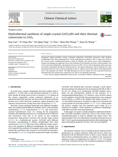
OriginalarticleHydrothermal synthesis of single-crystal CeCO3OH and their thermal conversion to CeO2Kun Gao a,Yi-Yang Zhu a,Da-Qing Tong a,Li Tian a,Zhao-Hui Wang a,b,Xiao-Zu Wang a,*a College of Chemistry and Chemical Engineering,Nanjing University of Technology,Nanjing210009,Chinab State Key Laboratory of Materials-Oriented Chemical Engineering,Nanjing University of Technology,Nanjing210009,China1.IntroductionIn recent years,cerium compounds have been widely used incatalysis[1–4],fuel cells[5]and chemical materials[6–8]due totheir specific4f energy levels of the Ce-element[9,10].Among allthe cerium compounds,cerium carbonate hydroxide,as animportant functional material,has been attracted much attentionbecause of its novel electronic properties,optical properties andchemical characteristics arising from their4f electrons[9–12].Recently,cerium carbonate hydroxide with different morphol-ogies was synthesized by different methods,such as self-assembly,sonochemical[13,14],hydrothermal[15–18],and microwave-assisted hydrothermal route[19].Among all the preparationmethods,the hydrothermal process is considered to be an effectiveand economical route due to its merits of low synthesistemperature,high powder reactivity and versatile shape control[20–23].In a hydrothermal system,CeCO3OH with differentstructures corresponding to distinct morphologies have beensynthesized[18,24,25].There have been sufficient studies report-ing on the synthesis of different morphologies,for example,Guoet al.reported the synthesis of triangular micro-plate,bundle-like,shuttle-like andflower-like structures of CeCO3OH by hydrother-mal method[15,16,18].Li and Zhao synthesized single-crystallineCeCO3OH with dendrite-like structures through a facile hydro-thermal method and obtained CeO2by heating CeCO3OH at5008Cfor6h[26].Zhang et al.synthesized CeCO3OH rhombic micro-plates by the precipitation method in the presence of3-aminopropyltriethoxysilane[28].However,most of these reportson the synthesis of CeCO3OH micro/nanoparticles were preparedusing CO(NH2)2or HMT as the alkaline and carbon resource[13–18]and added surfactant or template to adjust the nucleation andcrystal growth of CeCO3OH particles[13,15–18,28],which makesthe process complex and raw materials more costly.So it isimportant to explore a facile method to synthesize morphology-controlled CeCO3OH micro/nanomaterials.In this paper,we report a simple method to synthesize dendrite-like CeCO3OH crystallites using CeCl3Á7H2O as the cerium source,triethylenetetramine as both an alkaline and carbon source.Thepolycrystalline CeO2was obtained by calcination of the precursor at5008C for4h,partly maintaining the dendrite-like morphology.Theoptical absorption properties of CeO2were also investigated.2.ExperimentalAll chemical reagents were of analytical grade without furtherpurification.In a typical synthesis,0.001mol of CeCl3Á7H2O wasdissolved in60mL deionized water to form a clear solution,andthen0.30mL triethylenetetramine was added to the transparentsolution in order to completely react with Ce3+at258C for about0.5h with continued stirring.The resulting homogenous solutionChinese Chemical Letters25(2014)383–386A R T I C L E I N F OArticle history:Received10August2013Received in revised form8September2013Accepted26September2013Available online1December2013Keywords:CeCO3OHHydrothermalCerium carbonate hydroxideNanostructuresA B S T R A C THexagonal single-crystalline cerium carbonate hydroxide(CeCO3OH)precursors with dendritemorphologies have been synthesized by a facile hydrothermal method at1808C using CeCl3Á7H2O asthe cerium source,triethylenetetramine as both an alkaline and carbon source,with triethylenete-tramine also playing an important role in the formation of the dendrite structure.Polycrystalline ceria(CeO2)have been obtained by calcining the precursor at5008C for4h.The morphology of the precursorwas partly maintained during the heating process.The optical absorption spectra indicate the CeO2nano/microstructures have a direct band gap of2.92eV,which is lower than values of the bulk powderdue to the quantum size effect.The high absorption in the UV region for CeO2nano/microstructureindicated that this material was expected to be used as UV-blocking materials.ß2013Xiao-Zu Wang.Published by Elsevier B.V.on behalf of Chinese Chemical Society.All rightsreserved.*Corresponding author.E-mail address:wangxiaozu@(X.-Z.Wang).Contents lists available at ScienceDirectChinese Chemical Lettersj o u rn a l h om e p a g e:w w w.e l s e v i e r.c o m/l o c a t e/c c l e t1001-8417/$–see front matterß2013Xiao-Zu Wang.Published by Elsevier B.V.on behalf of Chinese Chemical Society.All rights reserved./10.1016/let.2013.11.047was transferred to a 100mL Teflon-line stainless steel autoclave,which was sealed and maintained at 1808C for 24h,and cooled to room temperature naturally.The white precipitate was collected by centrifugation,washed several times with distilled water and ethanol,and dried at 708C for 6h.The as-synthesized CeCO 3OH was calcined to produce straw-yellow CeO 2in air at 5008C for 4h.The XRD measurements were performed on a Bruker-D8Advanced X-ray diffractometer,equipped with graphite-monochromatizedhigh-intensity Cu K a radiation (l =1.5418A˚).The morphologies and sizes of the resulting products were examined by field-emission scanning electron microscopy (FESEM,Hitachi S-4800)and transmission electron microscopy (TEM,JEM2000EX),respec-tively.The thermal behavior of the resulting products was carried out by differential scanning calorimetric analysis (DSC)and thermogravimetric analysis (TG)with a Netzsch-449C simulta-neous TG/DSC apparatus heating from room temperature to 6008C (108C/min)in flowing air.UV/vis absorption spectra were acquired on a spectrophotometer (Shimadzu)and the analyzed range was 200–800nm.3.Results and discussionFig.1presents the typical XRD pattern of the as-synthesized CeCO 3OH products.All of the diffraction peaks in Fig.1can be exactly indexed to the pure hexagonal crystalline phase ofCeCO 3OH with lattice constants a =7.2382A˚,c =9.9596A ˚,which are in good agreements with the literature values (JCPDS 32-0189).No impurity peaks are detected,indicating the high purity of the final product.The strong and sharp diffraction peaks suggest that the products are highly crystallined.Fig.2shows a typical SEM image of the CeCO 3OH dendrite structure synthesized at 1808C for 24h.As shown in Fig.2,it reveals most of the as-prepared CeCO 3OH products display twofold-symmetric structures with a length of 1–2m m along the trunk.The detailed morphology of the structures of CeCO 3OH dendrites is further studied using TEM and SAED (Select-area electron diffraction).A typical high magnification TEM image of the structure of CeCO 3OH dendrites is shown in Fig.3.It reveals that the product is composed of a long central trunk with secondary and tertiary sharp branches,which are parallel to each other and emerge at 608angles with respect to the central trunk.The SAED pattern in the inset of Fig.3taken from an individual dendrite-like nanostructure is indexed to hexagonal CeCO 3OH,indicating that the individual is a single crystal.The diffraction pattern indicates the individual dendrite-like CeCO 3OH is well crystallized.The typical TG pattern of the as-prepared CeCO 3OH dendrite structure is shown in Fig.4a.The TG curve shows that CeCO 3OH begins to decompose at about 2808C and finishes at 6008C.Thetotal weight loss between 2808C and 6008C is measured at about 21.70%,which is close to the results in the theoretical value calculated from following reaction:4CeCO 3OH þO 2!4CeO 2þ2H 2O þ4CO 2(1)The DSC curve (Fig.4b)shows one endothermic peak with a maximum at 300.08C.The temperature range of the endothermic peak in the DSC curve agrees well with the weight loss in the TG curve,corresponding to endothermic behavior during the thermal decomposition/oxidation of CeCO 3OH to CeO 2.Fig.5shows the XRD pattern of CeO 2obtained by calcinations of as-prepared CeCO 3OH.All of the peaks are well assigned to pure face-centered cubic (fcc)structure of CeO 2with lattice constantsa =5.412A˚,which is in good agreement with the JCPDS card (No.43-1002).No obvious peaks for other elements or impurities were observed.The strong and sharp reflection peaks suggest that the as-prepared products are well crystallized.After the CeCO 3OH dendrites are calcined in air at 5008C for 4h,CeO 2dendrites are formed.As shown in Fig.6a,SEM image of CeO 2reveals that the dendrite morphology was partly sustained after thermal decomposition/oxidation to CeO 2.Fig.6b presents a typical TEM image of CeO 2dendrite and its corresponding ED pattern (Fig.6b inset).The discontinuous rings in ED pattern indicate that it could consist of CeO 2polycrystals with an oriented crystallographic axis.In our experiment,since triethylenetetramine was not used,noting products were obtained.Fig.7shows the SEM image of raw material (CeCl 3Á7H 2O),only erose particles were observed,indicating the triethylenetetramine plays an important role in the formation of CeCO 3OH dendrite structures.As is well known,triethylenetetramine at the room tempera-ture will release OH Àin the aqueous solution.Meanwhile,triethylenetetramine has large average capacities for the absorp-tion CO 2[27].So the CO 32Àanions in the solution may result from1020304050602θ (° )(002)(110)(112)(004)(300)(114)(302)(220)(222)(304)Fig.1.XRD patternof the CeCO 3OH dendrite-like nanostructure.Fig.2.SEM image of the as-synthesized CeCO 3OH.Fig.3.TEM image of the as-synthesized CeCO 3OH.K.Gao et al./Chinese Chemical Letters 25(2014)383–386384the possible oxidation of triethylenetetramine,the absorption andslight dissolution of CO 2from air.In the hydrothermal process,the C—N bond in triethylenete-tramine is the easiest bond to break,so upon heating to a certain temperature,triethylenetetramine hydrolyzes to form NH 4+and CO 32À.The cerium ions can exist in the form of [Ce(H 2O)n ]3+in aqueous solution,and then [Ce(H 2O)n ]3+is changed into [Ce(OH)(H 2O)n +]2+,and finally CeCO 3OH is obtained by the reaction between [Ce(OH)(H 2O)n À1]2+and CO 32À.It is proposed that dendrite structures are obtained through a seed-mediated growth in the presence of micelles of triethylenetetramine.The CeCO 3OH nuclei were created and used as seed center,these random moving nuclei in the environment can aggregate with each other to form anisotropic morphology.In our experiment,we consider that triethylenetetramine used as the alkaline and surfactant in the hydrothermal process.Therefore,existing triethylenetetramine,as a capping agent in the reaction system,is absorbed selectively on the different planes of CeCO 3OH seeds,helps to lower the surface energy and results in the different growth rate of different planes to form the dendrite structures.The real formation mechanism of CeCO 3OH dendrite structure needs further investigation.Fig.8shows the UV/vis diffuse absorption spectra of CeCO 3OH and CeO 2.Fig.8a shows the UV/vis absorption spectra for CeCO 3OH.The spectra displayed a strong absorption band below 400nm in the spectra.As seen in Fig.8b and 8c,when the synthesized particles were calcined to produce straw yellow CeO 2by heating at 5008C for 4h,the CeO 2has a stronger absorption band below 480nm in the spectra,which is originated from change-transfer transition between O 2p and Ce 4f bonds [28–30].The optional band gap E g can be determined based on the absorbance spectrum of the powders by the following equation:E g =1240/l AE ,where l AE is the edge wavelength of absorbance.The onset of absorption for CeO 2is at 425.3nm,which corresponds to the band gap energy (E g )of 2.92eV,lower than the values of bulk100200300400500600700800024681012←b. DSC cur veH e a t f l o w (m W /m g )Temerature (oC)← a . TG curve80859095100W e i g h t l o s s(%)Fig.4.TG-DSC pattern of the as-synthesized CeCO 3OH.10203040506070802θ (° )(111)(200)(220)(311)(222)(400)(311)(420)Fig.5.XRD pattern of the CeO 2sample.Fig.6.The typical SEM and TEM images of CeO 2obtained from thermal decomposition/oxidation of CeCO 3OH dendrite structure.Fig.7.SEM image of CeCl 3Á7H 2O powders.800700600500400300200b A b s o r b a n c e (a .u )Wavelength (nm)a800700600500400300200A b s o r b a n c e (a .u )Wavelength (nm)cFig.8.UV/vis absorption spectra of CeCO 3OH (a)and CeO 2(b),(c).K.Gao et al./Chinese Chemical Letters 25(2014)383–386385powders(3.19eV).In general,reduction in crystal size would increase the band gap width because of the quantum size effect [31].Hence,the high absorption in the UV region for CeO2show that the materials can be used as UV-blocking,shielding materials to avoid damage from ultraviolet rays and optical devices.4.ConclusionIn summary,we have successfully synthesized CeCO3OH dendrite structures by a facile hydrothermal method in the presence of triethylenetetramine.After annealing the CeCO3OH precursor powders at5008C for4h,CeO2nano/microstructures with dendrite morphology could be obtained with the morphology partly kept.It is believed that triethylenetetramine plays an important role in the growth of CeCO3OH dendrite structures.The optical absorption spectra indicate that the CeO2nano/microstruc-ture have a direct band gap of2.92eV,which is lower than the values of bulk powders.It is expected that these materials canfind potential application in catalysis and UV-blocking material. AcknowledgmentsThis work was supportedfinancially by the Program for Innovative Research Team in Jiangsu Province(No.SZK[2011]87), Creative and Innovative Talents Introduction Plan(No.SZT[2011]43) and Special Research Foundation of Young teachers of Nanjing University of Technology(No.39701007).References[1]D.Andreeva,I.Ivanov,L.Ilieva,et al.,Nanosized gold catalysts supported on ceriaand ceria–alumina for WGS reaction:influence of the preparation method, Powder Technol.333(2007)153–160.[2]rese,M.L.Granados,F.C.Galisteo,et al.,TWC deactivation by lead:a study ofthe Rh/CeO2system,Appl.Catal.B62(2006)132–143.[3]Y.Dai,B.D.Li,H.D.Quan,et al.,CeCl3Á7H2O as an efficient catalyst for one-potsynthesis of b-amino ketones by three-component Mannich reaction,Chin.Chem.Lett.21(2010)31–34.[4]M.Hajjami,A.G.Choghamarani,M.A.Zolfigol,et al.,An efficient and versatilesynthesis of aromatic nitriles from aldehydes,Chin.Chem.Lett.23(2012) 1323–1326.[5]G.Jacobs,L.Williams,U.Graham,et al.,Low-temperature water–gas shift:in-situDRIFTS reaction study of a Pt/CeO2catalyst for fuel cell reformer applications,J.Phys.Chem.B107(2003)10398–10404.[6]M.S.Tsai,Powder synthesis of nano grade cerium oxide via homogenous precipi-tation and its polishing performance,Mater.Sci.Eng.B110(2004)132–134. [7]D.S.Lim,J.W.Ahn,H.S.Park,et al.,The effect of CeO2abrasive size on dishing andstep height reduction of silicon oxidefilm in STI–CMP,Surf.Coat.Technol.200 (2005)1751–1754.[8]Y.H.Kim,S.K.Kimb,N.Kimb,et al.,Crystalline structure of ceria particlescontrolled by the oxygen partial pressure and STI CMP performances,Ultramicro-scopy108(2008)1292–1296.[9]A.W.Xu,Y.Gao,H.Q.Liu,The preparation,characterization,and their photo-catalytic activities of rare-earth-doped TiO2nanoparticles,J.Catal.207(2002) 151–157.[10]D.C.Koskenmaki,K.A.Gschneidner Jr.,Handbook on the Physics and Chemistry ofRare Earths,vol.1,North-Holland,Amsterdam,1978,pp.338–340.[11]Y.G.Sun,B.Mayers,Y.N.Xia,Template engaged replacement reaction:a one stepapproach to the large scale synthesis of metal nanostructures with hollow interiors,Nano Lett.3(2003)675–679.[12]A.P.Alivisatos,Semiconductor clusters,nanocrystals,and quantum dots,Science271(1996)933–937.[13]K.Li,P.S.Zhao,Synthesis and characterization of CeCO3OH one-dimensionalquadrangular prisms by a simple method,Mater.Lett.63(2009)2013–2015.[14]Z.Y.Guo,F.F.Jian,F.L.Du,Sonochemical synthesis of luminescent CeCO3OH one-dimensional quadrangular prisms,Mater.Res.Bull.207(2011)35–41.[15]Z.Y.Guo, F.L.Du,G.C.Li,et al.,Synthesis and characterization of single-crystal Ce(OH)CO3and CeO2triangular microplates,Inorg.Chem.45(2006) 4167–4169.[16]Z.Y.Guo,F.L.Du,G.C.Li,et al.,Synthesis and Characterization of bundle-likestructures consisting of single crystal Ce(OH)CO3nanorods,Mater.Lett.61(2007) 694–696.[17]M.Y.Cui,J.X.He,N.P.Lu,et al.,Morphology and size control of cerium carbonatehydroxide and ceria micro/nanostructures by hydrothermal technology,Mater.Chem.Phys.121(2010)314–319.[18]Z.Y.Guo,F.L.Du,G.C.Li,et al.,Hydrothermal synthesis of single-crystallineCeCO3OHflower-like nanostructures and their thermal conversion to CeO2, Mater.Chem.Phys.113(2009)53–56.[19]E.L.Qi,L.Y.Man,S.H.Wang,et al.,Microwave homogeneous synthesis andphotocatalytic property of CeO2nanorods,Chin.J.Mater.Res.25(2011)221–224.[20]L.Yan,R.B.Yu,J.Chen,et al.,Template-free hydrothermal synthesis of CeO2nano-octahedrons and nanorods:investigation of the morphology evolution,Cryst.Growth Des.8(2008)1474–1477.[21]X.J.Yang,X.P.Li,X.T.Bai,et al.,Facile synthesis and characterization of uniformCdS colloidal spheres,Chin.Chem.Lett.23(2012)1091–1094.[22]W.T.Yao,S.H.Yu,Recent advances in hydrothermal syntheses of low dimensionalnanoarchitectures,Int.J.Nanotechnol.4(2007)129–162.[23]D.Zhao,J.S.Tan,Q.Q.Ji,et al.,Mn2O3nanomaterials:facile synthesis andelectrochemical properties,Chin.J.Inorg.Chem.26(2010)832–838.[24]Z.H.Han,N.Guo,K.B.Tang,et al.,Hydrothermal crystal growth and characteri-zation of cerium hydroxycarbonates,J.Cryst.Growth219(2000)315–318. [25]C.H.Lu,H.C.Wang,Formation and microstructural variation of cerium carbonatehydroxide prepared by the hydrothermal process,Mater.Sci.Eng.B90(2002) 138–141.[26]K.Li,P.S.Zhao,Synthesis of single-crystalline Ce(CO3)(OH)with novel dendritemorphology and their thermal conversion to CeO2,Mater.Res.Bull.45(2010) 243–246.[27]Z.Wang,M.X.Fang,Y.L.Pan,et al.,Amine-based absorbents selection for CO2membrane vacuum regeneration technology by combined absorption–desorp-tion analysis,Chem.Eng.Sci.93(2013)238–249.[28]Y.W.Zhang,R.Si,C.S.Liao,et al.,Facile alcohothermal synthesis,size-dependentultraviolet absorption,and enhanced CO conversion activity of ceria nanocrystals, J.Phys.Chem.B107(2003)10159–10167.[29]N.Imanaka,T.Masui,H.Hirai,et al.,Amorphous cerium–titanium solid solutionphosphate as a novel family of band gap tunable sunscreen materials,Chem.Mater.15(2003)2289–2291.[30]S.Tsunekawa,T.Fukuda,A.Kasuya,Blue shift in ultraviolet absorption spectra ofmonodisperse CeO2Àx nanoparticles,J.Appl.Phys.87(1999)1318–1321. [31]Y.B.Yin,X.Shao,L.M.Zhao,et al.,Synthesis and characterization of CePO4nanowires via microemulsion method at room temperature,Chin.Chem.Lett.20(2009)857–860.K.Gao et al./Chinese Chemical Letters25(2014)383–386 386。
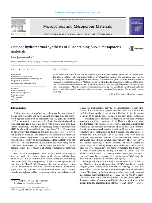
One-pot hydrothermal synthesis of Al-containing SBA-3mesoporousmaterialsEwa Janiszewska ⇑Adam Mickiewicz University,Faculty of Chemistry,Grunwaldzka 6,60-780Poznan,Polanda r t i c l e i n f o Article history:Received 8December 2012Received in revised form 9February 2014Accepted 10March 2014Available online 18March 2014Keywords:AlSBA-3synthesisAluminium incorporation Acidic properties FTIR +pyridine NH 3-TPDa b s t r a c tAlSBA-3mesostructured materials with different Si/Al ratios were directly synthesized for the first time.The influence of the synthesis medium (different pH of synthesis mixture)and aluminium source on the efficiency of aluminium incorporation was studied.The increase in pH of reacting mixture allows to introduce much higher number of Al atoms,but on the other hand it causes worse ordering of the struc-ture.The aluminium isopropoxide used as Al source leads to relatively high Al content in the final mate-rials.The presence of Al in the framework positions is proved by 27Al MAS NMR.The obtained materials show considerable catalytic activity for the acid-catalyzed reactions (dehydration of 2-propanol,cumene cracking).Ó2014Elsevier Inc.All rights reserved.1.IntroductionZeolites,due to their regular arrays of uniformly sized channels,strong surface acidity and large amount of active sites are exten-sively applied in industry as heterogeneous catalysts and sorbents [1].Processing of large organic molecules in fine chemical produc-tion often requires a molecular sieve with a larger pore size than that of conventional zeolites.The discovery of ordered mesoporous M41S family with controllable pore size from 1.5to 10nm offers an opportunity for processing of bulky molecules [2,3].However,the acidity of alumino-and metalosilicate mesoporous materials is always distinctively lower compared with zeolites [4,5].Limited hydrothermal stability of these materials,either in steam or in hot water [6,7]restricts their broad application.Therefore many efforts have been undertaken to improve their stability [8–11]or to prepare other,more robust and stable,mesoporous materials [9,12,13].SBA-15silica mesoporous materials [13]with more regular structure and thicker walls show much higher stability than MCM-41[14]due to contribution of some micropores connecting mesopores [15].The microporosity of SBA-3is more pronounced than those in SBA-15[16].However,the absence of active sites in the framework of these all siliceous materials limits their applications.Incorporation of aluminium or other metal cations into the amorphous walls of mesoporous silica materials is crucialto generate their catalytic activity [4].Nevertheless,it is very diffi-cult to incorporate metal species into the SBA-n siliceous frame-work by direct synthesis due to the difficulties in the formation of metal–O–Si bonds under required strongly acidic conditions [17].Therefore,most attempts are focused on the post-synthesis incorporation of heteroatoms [18,19].However,there are some disadvantages with these processes,such as complex experimental conditions,non uniform distribution of active sites and contribu-tion of extra-framework species which could block the channels.Therefore,it is challenging to find a simple one-step route to prepare the metalosilicate SBA-n materials with well ordered structure,uniform distribution of the heteroatoms within the framework and efficient catalytic functionality.There are only a few papers reporting a direct synthesis of metal-substituted SBA-n materials including the synthesis under weak acidic condi-tions [20],‘‘pH-adjusting’’[21],semi-crystallizing the framework or using zeolite units to modify the wall of SBA-n [22].For AlSBA-15and AlSBA-1both post-synthesis alumination and direct synthesis have been reported [19],while for AlSBA-3only the post-synthesis methods have been developed [23,24].Although the thermal and hydrothermal resistance of SBA-15and SBA-3are similar,the procedure of SBA-3synthesis is much simpler (lower temperature,one step of heating).It was also reported that the efficiency of niobium incorporation into the skel-eton of SBA-3was the highest amongst other hexagonally ordered mesoporous materials (like MCM-41,SBA-15).The NbSBA-3mate-rials were also more effective catalysts in gas phase oxidative dehydrogenation of propane and liquid phase oxidation of cyclo-hexene than the corresponding NbMCM-41and NbSBA =15[25]./10.1016/j.micromeso.2014.03.0131387-1811/Ó2014Elsevier Inc.All rights reserved.⇑Tel.:+48618291239;fax:+48618291555.E-mail address:eszym@.plThe aim of this study was a direct synthesis of AlSBA-3contain-ing exclusively tetrahedrally coordinated aluminium.The influence of aluminium source as well as the pH of the initial mixture on the textural and surface properties of obtained samples was investi-gated.The resulted materials were characterized by various phys-icochemical methods that prove an incorporation of aluminium into the structure and assess their structural/textural properties. The evaluation of the acidic properties of the materials has been estimated by means of NH3-TPD,FTIR with adsorbed pyridine as probe molecule and by catalytic test of2-propanol dehydration and cumene cracking.2.Experimental2.1.SynthesisAll SBA-3materials were synthesized according to the proce-dure reported by Stucky et al.[26].Cetyltrimethylammonium bro-mide(CTABr,Aldrich)and tetraethylorthosilicate(TEOS,Aldrich) were used as a porogeneous agent and silica source,respectively. Aluminium nitrate(Al(NO3)3Á9H2O,POCh,Poland),aluminium iso-propoxide(Al(isop)3,Aldrich)or aluminium sulphate(Al2(SO4)3-Á16H2O,POCh)were used as aluminium precursors.Concentrated HCl aqueous solution(37%,POCh)was used as the acid source. Aqueous ammonia(25%,POCh)was used to adjust the pH of the initial mixture.The aluminosilicate SBA-3samples were synthe-sized in strongly acidic condition according to following proce-dure:CTABr was dissolved in diluted HCl and then solution of aluminium source was admitted dropwise to the acidic CTABr solution.After stirring for15min,TEOS was added gradually(Si/ Al=50–2)with continuous stirring for next30min.It resulted in formation of white gel.The molar composition of the gel was1 Si:0.02–0.5Al:0.125CTABr:10.9HCl:164H2O.The typical strongly acidic medium was used for preliminary syntheses.In further experiments pH of the suspension was increased up to 2.2or 3.1value,respectively with aqueous ammonia.Stirring was continued for another2h and then the mixture was left at ambient,static condition for22h.The resulting precipitate was filtered,dried and calcined in air at550°C for8h.The same proce-dure was used for Al-free SBA-3for comparison.The samples were labeled as follows:x Al-y(z)where:x stands for Si/Al ratio,y stands for pH of the synthesis:2for synthesis at pH=2.2,3for synthesis at pH=3.1,z defines Al source:(n)–alumin-ium nitrate,(s)–aluminium sulphate,(i)–aluminium isopropoxide.2.2.CharacterizationThe obtained samples were characterized by means of standard methods.X-ray diffraction(XRD)patterns were recorded using a Bruker D8Advance diffractometer with Cu K a radiation (k=1.54056Å).Aluminium content in the calcined samples was determined by ICP–OES on a Varian Vista-MPX spectrometer.The BET surface area and pore parameters of the samples were deter-mined by nitrogen adsorption–desorption isotherm measurements at77K on a Quantachrome Nova1000sorptometer.The samples were outgassed at300°C prior to the measurement.Pore size dis-tribution were calculated from the desorption branch of the isotherm by the Barrett-Joyner-Halenda(BJH)method.The micro-porous surface was estimated using the t-plot method.Solid27Al MAS NMR analysis was performed on a Bruker AMX300WB spec-trometer.Solid29Si MAS NMR analysis was performed on a Varian 400MHz spectrometer.The Fourier transform infrared spectra were recorded with Bruker Tensor27spectrophotometer.Pyridine was used as basic probe agent.The samples were pressed under low pressure into a thin wafers and placed in the vacuum cell.The samples were outgased at400°C for2h and then pyridine was adsorbed at room temperature.The desorption was carried out for30min at each of the following temperatures:100,200, 300and400°C.The spectra were recorded at room temperature. NH3-TPD measurements were performed in aflow reactor.In a typical experiment,about40mg of sample was heated in He stream at the rate of10°/min up to500°C and kept at that temper-ature for0.5h,then cooled down to120°C and afterwards satu-rated with ammonia for0.5h.The physically adsorbed NH3was removed by purging with heliumflow at120°C for1h.The TPD analysis was carried in a range100–600°C with a heating rate 10°C/min.The desorbed NH3was detected and recorded by a TCD analyzer.The catalytic activity of the samples were examined in the 2-propanol(POCh)decomposition and cumene cracking(Aldrich). The catalytic tests were conducted in a pulse microreactor at-tached to the gas chromatograph(Chrom-5)equipped with TCD. The catalyst powder samples(0.015g)were activated in helium stream at350°C(2-propanol)or450°C(cumene)for0.5h prior to the catalytic tests.The decomposition of2-propanol was carried out at230°C and cumene craking at350°C for all samples.The volume of the injected substrate was1l l.3.Results and discussion3.1.X-ray diffractionThe pore ordering of the samples was confirmed by low angle XRD analysis.The presence of aluminium in the reacting mixture did not disturb the formation of SBA-3structure.As displayed in Fig.1,the samples showed typical patterns of the hexagonal phase of SBA-3,matching well those reported in the literature[23].The XRD patterns of AlSBA-3samples showed three well-resolved sharp peaks of higher intensity in comparison to intensity of peaks of all silica SBA-3samples.It indicated better ordering of AlSBA-3 samples than that of pure silica SBA-3(Fig.1A).Probably it can be caused by promoting role of anion accompanying the Al atoms which could affect the interaction of the surfactant with the silicate species.Similar effect was observed in synthesis of MCM-41mate-rials[27]or zeolites[28].The addition of some amount of certain anions to the synthesis mixture of MCM-41materials or zeolites reduced the synthesis time.The increase in pH of initial mixture resulted in a little lower intensity of XRD reflections which can re-sult from lower ordering of the products(Fig.1B).The source of aluminium does not influence the ordering markedly(Fig.1C).XRD patterns in the wide angle range were recorded in order to check the presence of any crystalline phase in resulted samples. We did not notice any distinct diffraction reflections corresponding to any crystalline phase(Fig.2),although some sensitivity limits of XRD in case of low content,small particles(below3nm)or very high dispersion of potential admixture should be taken into an ac-count.Only very broad band in the2h range15–30°is noticeable, which is always attributed to amorphous silica.3.2.Low-temperature nitrogen adsorption and ICP resultsThe composition and textural properties of resulting mesopor-ous materials are shown in Table1.The elemental analyses of all samples indicate much lower Al content in the products than in starting gels.It indicates that only a small fraction of aluminium is included into the walls.The same observations were reported for Al-bearing SBA-15or SBA-1[17,19,29].The low content of Al introduced into the products results from the fact,that applied acidic medium is much below isoelectric point of Al3+cations and subsequently difficult formation of Si–O–Al bands.The78 E.Janiszewska/Microporous and Mesoporous Materials193(2014)77–84isomorphous substitution of silicon in SBA-3for aluminium strongly depends on the Al source and pH of the synthesis mixture,as evidenced by the data in Table parison of the aluminium content in samples synthesized with the same source of alumin-ium (i.e.nitrate)at different pH in range 2–3indicates that in-crease in pH of the reacting mixture results in negligible augmentation of Al number.The Al 3+cations and positive charge of silica species existing in the synthesis mixture at low pH (<1)do not interact with each other because of the same charge.There-fore aluminium atoms are not introduced to the structure.If the pH of the synthesis mixture rises above the zero net charge of silica (pH >2),the Si species become negatively charged which enhances the interaction with the Al 3+species.The use of Al(NO 3)3or Al 2(SO 4)3causes the introduction of the lowest amount of alumin-ium,whereas the use of Al(isop)3allows to introduce the highest amount of aluminium under the same condition of syntheses.As the condition of synthesis are similar (pH,time of synthesis)the differences in the amount of introduced Al atoms can be caused by different reactivity of the Al species in the gel formed of the three aluminium sources towards bonding with Si species during the gelation process.The samples obtained with using inorganic source of aluminium (nitrate or sulphate)indicate similar AlTable 1Structural properties of samples.SampleSynthetic conditions Si/Al (ICP)S BET (m 2g À1)S mic /S macV pore (cm 3g À1)Aver.pore diam.(nm)Source of AlpH Si/Al (gel)Si-0–<11–107111.80.49 2.4550Al-0(n)Nitrate <1501126912.60.66 2.37Si-2–2.21–9537.30.46 2.6650Al-2(n)Nitrate 2.2503031081 6.30.76 2.8320Al-2(n)Nitrate 2.220314133111.00.76 2.3010Al-2(n)Nitrate 2.210135155715.70.78 2.002Al-2(n)Nitrate 2.2249.5163815.20.73 2.19Si-3–3.11–74811.70.45 2.4250Al-3(n)Nitrate 3.150********.40.81 2.8520Al-3(n)Nitrate 3.120178132712.40.71 2.1310Al-3(n)Nitrate 3.110103149815.70.70 1.882Al-3(n)Nitrate 3.1235.6151720.70.64 1.7050Al-2(s)Sulphate 2.25067786910.70.56 2.5720Al-2(s)Sulphate 2.220357126112.80.69 2.1910Al-2(s)Sulphate 2.210169135413.90.73 2.162Al-2(s)Sulphate 2.2236149217.00.64 1.7150Al-2(i)Isopropox 2.2501431056 6.90.73 2.7520Al-2(i)Isopropox 2.22060123310.50.64 2.0810Al-2(i)Isopropox 2.21026.7136014.20.65 1.912Al-2(i)Isopropox2.224.4107815.30.511.86‘‘–‘‘–Not measured.E.Janiszewska /Microporous and Mesoporous Materials 193(2014)77–8479content.Substantially higher Al loading in samples prepared with Al(isop)3can result from the presence of isopropanol generated upon hydrolysis which affects somewhat polarity of the system and does not generate additional anions(NO3Àor SO42À)potentially competing with silicate,therefore it facilitates bonding the liber-ated Al3+cations with just formed silicic acid.The recorded nitrogen adsorption/desorption isotherms are of type IV characteristic for mesoporous materials.The pure silica and aluminosilicate materials synthesized at higher pH show sim-ilar isotherms.Only samples,prepared at pH=2.2and3.1with Si/ Al molar ratio of50,show an isotherms with a steep rise in adsorbed volume at relative pressure p/p0>0.8,corresponding to relatively larger pore size(Table1).As the relative pressure increases to ca.p/p0$0.2isotherms of all samples containing alu-minium show a sharp step characteristic of capillary condensation of nitrogen within uniform mesopores(Fig.3A and C).Uniformity of mesopores of aluminosilicate samples is well visible in pore size distribution curves(Fig.3B).The other textural parameters vary more or less depending on the pH,source of aluminium or Al con-tent.The surface area and pore volume slightly decreases with growing pH of the synthesis mixture(regardless of the aluminium presence).This effect can be explained regarding the rate of silica condensation.At an elevated pH value a higher degree of silicate condensation is attained.The more rapid condensation should not impair the micelles markedly and subsequently less pro-nounced interaction lead to a lower surface area and pore volume. The presence of Al in the initial mixture results in some increase in surface area and pore volume in comparison to all silica SBA-3even if aluminium atoms are not incorporated into the resulted struc-ture(sample Si-0and50Al-0(n)).As the synthesis of SBA-3mate-rials is performed in a relatively short time(22h)it can be the effect of promoting action of anions accompanying aluminium that allow to obtain better ordering of the structure.These observation was also confirmed by XRD analysis.The synthesis in the presence of NO3Àanions allows to obtain higher BET value in comparison to the series obtained in the presence of SO42À.The same effect was observed by Laha et al.in the synthesis of MCM-41[27].The authors showed,that at the same promoter concentration,the time required for obtaining a well-ordered MCM-41decreased with increasing charge/radius(Z/r)ratio of the central atom of the pro-moter anion.It explain better promoting role of nitrate in compar-ison to sulphate anion.The pH does not affect the pore diameter and volume for all silica samples,whereas introduction of Al results in their increase.Pore volume for the series of samples synthesized in the presence of nitrate and sulphate at pH=2.2 increases up to Si/Al ratio of10and then decreases.In series pre-pared with Al isopropoxide at pH=2.2and nitrate at pH=3.1the pore volume decreases with aluminium content.The average pore diameter also decreases with the growing Al content in the mate-rials for all the studied series.The decreasing pore volume and average pore size can be explained by increasing contribution of micropores with increasing Al loading calculated by t-plot method (Table1).The second possible explanation of lower pore volume for the samples with the highest amount of Al is a blocking the pores by extra-framework aluminium species(observed in27Al MAS NMR spectra).All textural parameters are slightly higher for samples synthesized in the presence of aluminium nitrate (amongst all series synthesized at the same pH with different Al source).It is a result of mentioned before the best promoting role of nitrate groups.3.3.Promoting role of oxyanions on SBA-3structure formationThe hydrothermal syntheses of all silica SBA-3at pH=2.2were carried out in the presence or absence of sodium salts of nitrate or sulphate to check the promotion role of these oxyanions on the course of syntheses of SBA-3structure.Different SiSBA-3series were preparing by varying the synthesis time(0–22h).The con-centration of promoter was the same(oxyanion/Si molar ratio was0.05).The XRD patterns of samples obtained at different time show that the synthesis of ordered SiSBA-3materials in the pres-ence of nitrate or sulphate anions is faster than in their absence (Fig.4).It proves the promoting role of these anions in the synthe-sis of SBA-3materials.Similarly as in the synthesis of MCM-41[27] the promoting role of nitrate is slightly better than sulphate anion. Similar conclusion provide29Si MAS NMR analysis of samples ob-tained at different times in the presence or absence of these oxya-nions.It is seen,that the ratio of Q4peak(more condensed(SiO)4Si species)to Q3peak(less condensed(SiO)3SiOH species)is higher for samples obtained in the presence of nitrate or sulphate than in that prepared without any promoter,regardless of time of synthesis(Fig.5).It clearly indicates a faster formation of ordered SBA-3structure in the presence of promotors.80 E.Janiszewska/Microporous and Mesoporous Materials193(2014)77–843.4.Metal locationSolid state27Al MAS NMR spectra provide the information on the aluminium species in the samples and confirm an introduction of aluminium atoms into the framework for samples synthesized at higher pH(Fig.6).The signal at46ppm is assigned to tetrahedrally coordinated aluminium species[18,30].The absence of signal around0ppm,corresponding to the octahedrally coordinated alu-minium,indicates that no extra-framework alumina species were formed even upon calcination.Only spectra of calcined samples with the highest Al content indicates some amount of extra-frame-work alumina(À5.5ppm).Lack of any signal in the spectra of sam-ples synthesized at pH<1indicates the absence of any Al in this sample.The all silica composition of the latest sample is also con-firmed by the ICP-OES analysis.3.5.Acidity measurementsThe IR spectra of adsorbed pyridine were measured in order to estimate the strength and nature of acid sites in AlSBA-3materials. All the samples indicate the FTIR bands due to pyridine adsorbed on Lewis acid sites(1455cmÀ1),pyridine adsorbed on Brönsted acid sites(1544cmÀ1)and a band at1490cmÀ1attributed to pyr-idine associated with both Lewis and Brönsted acid sites[31,32].Only the series of samples obtained with aluminium sulphate do not show any band attributed to strong(Brönsted)acid sites even for sample with highest amount of aluminium(Fig.7B).The spec-tra show the bands at1446and1596cmÀ1at lower pyridine desorption temperature due to pyridine hydrogen bonds with sila-nols group and band at1575cmÀ1assigned to weak Lewis-bound pyridine(Fig.8B).Bands attributed to hydrogen-bonded pyridine decay after evacuation at300°C.The band originated from weak Lewis-bound pyridine decays after desorption of pyridine at 300°C only for samples with low aluminium content,whereas it maintains even after evacuation at400°C for samples with high Al loading.Fig.8A compares of chemisorption of pyridine on sam-ples at300°C for samples with different Si/Al ratios synthesized with Al(isop)3.The intensity of band at1455cmÀ1due to Lewis acid sites is much higher in comparison to the intensity of band as-signed to Brönsted acid sites for all series indicating higher amount of Lewis acid sites in samples.The intensity of bands attributed to both,Lewis and Brönsted acid sites,increase with increasing amount of aluminium in the samples.This indicate that the acidity increases with increasing aluminium content.The FTIR spectra of pyridine adsorption on pure silicas SBA-3(sample Si-0or 50Al-0(n),not shown)show no peaks at1455or1544cmÀ1attributed to Lewis and Brönsted acid sites,respectively.The strength of acid sites was evaluated by NH3-TPD analysis. The TPD profiles of all samples show one broad peak in the temper-ature range of200–550°C with maximum at300°C(Fig.9).It cor-responds to the desorption of NH3from the weak,medium and strong acid sites of the materials with great majority of medium acid sites[31].The number of acid sites,calculated(Table2)as well reflected by the amount of chemisorbed ammonia is highest for samples synthesized with isopropoxide and in series increases with Al/Si ratio in starting gel(Fig.9B).These results are in good agreement with activity in reactions requiring acid sites.The aluminosilicate SBA-3materials under study show a remarkable activity in2-propanol decomposition which is in con-trast to all silica samples(Fig.10A).The dehydration reaction to propene results from action of the acid sites on the surface of cat-alysts due to the presence of Al atoms in the structure.The pres-ence of such centres was indicated in the NH3-TPD and FTIR with pyridine as a sonde measurements.The activity increases with the Al content in initial gels for all series and it is consistent with the number of introduced aluminium atoms.The samples obtained by using aluminium sulphate show the lowest activity,whereas the samples synthesized in the presence of aluminium isopropox-ide show the highest activity amongst series synthesized at theE.Janiszewska/Microporous and Mesoporous Materials193(2014)77–848182 E.Janiszewska/Microporous and Mesoporous Materials193(2014)77–84same pH.The series of samples obtained at higher pH show insig-nificant higher activity than the series obtained at lower pH(with the same source of aluminium)due to much higher aluminium content.The samples with the highest aluminium loading show some activity(11–13%)in cumene cracking(Fig.10B).Only the samples synthesized with aluminium sulphate show negligible activity in this reaction similarly as samples of all series with lower aluminium loading suggesting a weak acid strength of their active centres.These results are in good agreement with FTIR with pyri-dine as a sond results.4.ConclusionsThe results reveal for thefirst time that Al can be successfully incorporated into SBA-3by direct synthesis.The presence of Al atoms in tetrahedral framework positions of SBA-3structure has been confirmed by27Al MAS-NMR measurement.The number of Al incorporated in SBA-3structure depends on used source of alu-minium and on pH of synthesis mixture.Some increase in pH of initial mixture is necessary to introduce Al to the structure. Aluminium isopropoxide used as aluminium source allows to introduce the highest amount of aluminium without altering the structural ordering and the textural features.The IR spectra of ad-sorbed pyridine indicate the presence of both Lewis and Broensted acid sites in the samples with introduced Al and the above results are consistent with these of NH3-TPD data exhibiting the prevailing contribution of medium acidic sites.The catalytic activity of theTable2Total number of acid sites evaluated by NH3-TPD(l mol/g).Al/Si pH=2.2pH=3.1 Nitrate Sulphate Isopropoxide Nitrate0.02––––0.0526–39290.125886370.518741320177‘‘–‘‘–Not measured.5020102Si/Al 5020102 isopropox.nitrate, pH=3.1Si/AlFig.10.Conversion(%)2-propanol over samples.E.Janiszewska/Microporous and Mesoporous Materials193(2014)77–8483samples in reaction requiring acidic active sites(2-propanol dehy-dration,cumene cracking)depends on the number of aluminium incorporated into the siliceous framework.AcknowledgmentThe author appreciate National Science Centre forfinancial support from Grant No.N204119238.References[1]G.Bellussi,M.S.Rigutto,in:J.C.Jansen,M.Stöcker,H.G.Karge,J.Weitkamp(Eds.),Advanced Zeolite Science and Applications,Stud.Surf.Sci.Catal.,vol.85, Elsevier,Amsterdam,1994,pp.177–213.[2]J.S.Beck,J.C.Vartuli,W.J.Roth,M.E.Leonowicz,C.T.Kresge,K.D.Schmitt,C.T.-W.Chu,D.H.Olson,E.W.Sheppard,S.B.McCullen,J.B.Higgins,J.L.Schlenker,J.Am.Chem.Soc.114(1992)10834–10843.[3]C.T.Kresge,M.E.Leonowicz,W.J.Roth,J.C.Vartuli,J.S.Beck,Nature359(1992)710–712.[4]A.Corma,Chem.Rev.97(1997)2373–2420.[5]A.Corma,V.Fornés,M.T.Navarro,J.J.Pérez-Pariente,J.Catal.148(1994)569–574.[6]J.M.Kim,J.H.Kwak,S.Jun,R.Ryoo,J.Phys.Chem.99(1995)16742–16747.[7]D.Trong On,S.M.J.Zaidi,S.Kaliaguine,Micropor.Mesopor.Mater.22(1998)211–224.[8]J.M.Kim,S.Jun,R.Ryoo,J.Phys.Chem.B103(1999)6200–6205;R.Ryoo,S.Jun,J.M.Kin,M.J.Jim,mun.(1997)2225–2226.[9]K.R.Kloetstra,H.Van Bekkum,J.C.Jansen,mun.(1997)2281–2282.[10]R.Mokaya,W.Jones,mun.1997(2185–2186)(1998)1839–1840.[11]R.Mokaya,Angew.Chem.111(1999)3079;R.Mokaya,Angew.Chem.Int.Ed.Engl.38(1999)2930–2934.[12]S.S.Kim,W.Zhang,T.J.Pinnavaia,Science282(1998)1302–1305.[13]D.Y.Zhao,J.Feng,Q.Huo,N.Melosh,G.H.Fredickson,B.F.Chmelka,G.D.Stucky,Science279(1998)548–552.[14]F.Kleitz,W.Schmidt,F.Schüth,Micropor.Mesopor.Mater.65(2003)1–29.[15]R.Xu,W.Pang,J.Yu,Q.Huo,J.Chen,Chemistry of Zeolites and Related PorousMaterials:Synthesis and Structure,J.Wiley&Sons(Asia)P LTD,Singapore, 2007.pp.467–601.[16]R.Ryoo,C.H.Ko,M.Kruk,V.Antochshuk,M.Jaroniec,J.Phys.Chem.B104(2000)11465–11471.[17]A.Vinu,V.Murugesan,W.Böhlmann,M.Hartmann,J.Phys.Chem.B108(2004)11496–11505.[18]N.Lin,Y.Yang,Z.Y.Wu,H.J.Wang,J.H.Zhu,Micropor.Mesopor.Mater.139(2011)130–137.and references therein.[19]M.Hartmann,A.Vinu,S.P.Elangovan,V.Murugesan,W.Böhlmann,Chem.Commun.11(2002)1238–1239.and references therein.[20]Y.Yue,A.Gédéon,J.-L.Bonardet,N.Melosh,J.-B.D’Espinose,J.Fraissard,Chem.Commun.(1999)1967–1968.[21]S.Wu,Y.Han,Y.-C.Zou,J.-W.Song,L.Zhao,Y.Di,S.-Z.Liu,F.-S.Xiao,Chem.Mater.16(2004)486–492.[22]D.T.On,S.Kaliaguine,Angew.Chem.Int.Edit.40(2001)3248–3251.[23]O.A.Anunziata,M.L.Martínez,M.G.Costa,Mater.Lett.64(2010)545–548.[24]M.L.Martínez,M.B.Gómez Costa,G.A.Monti,O.A.Anunziata,Micropor.Mesopor.Mater.144(2011)183–190.[25]B.Kilos,A.Tuel,M.Ziolek,J.C.Volta,Catal.Today118(2006)416–424.[26]Q.Huo,D.I.Margolese,U.Ciesla,D.G.Demuth,P.Feng,T.E.Gier,P.Sieger,A.Firouzi,B.F.Chmelka,F.Schüth,G.D.Stucky,Chem.Mater.6(1994)1176–1191.[27]ha,R.Kumar,Micropor.Mesopor.Mater.53(2002)163–177.[28]R.Kumar,P.Mukherjee,R.K.Pandey,P.Rajmohanan,A.Bhaumik,Micropor.Mesopor.Mater.22(1998)23–31.[29]V.V.Balasubramanian,C.Anand,R.R.Pal,T.Mori,W.Böhlmann,K.Ariga,A.K.Tyagi,A.Vinu,Micropor.Mesopor.Mater.121(2009)18–25.[30]G.Engelhardt,in:H.van Bekkum,E.M.Flanigen,P.A.Jacobs,J.C.Jansen(Eds.),Introduction to Zeolite Science and Practice,2nd Revised and Expanded Edition,Stud.Surf.Sci.Catal.,vol.137,Elsevier,Amsterdam,2001,pp.387–418.[31]Y.Li,W.Zhang,L.Zhang,Q.Yang,Z.Wei,Z.Feng,C.Li,J.Phys.Chem.B108(2004)9739–9744.[32]T.Klimova,J.Reyes,O.Gutiérrez,L.Lizama,Appl.Catal.A335(2008)159–171.84 E.Janiszewska/Microporous and Mesoporous Materials193(2014)77–84。
xx大学全日制硕士专业学位论文磷酸铁形貌特征对磷酸铁锂电化学性能的影响磷酸铁形貌特征对磷酸铁锂电化学性能的影响摘要锂离子电池是第三代可充二次电池,因具有工作电压高、比容量较高、循环寿命长、对环境污染小等特点,近年来成为化学电源领域的研究热点,具有广阔的应用前景。
相对于Ni-Cd、Ni-MH及铅酸电池这类传统的二次电池来说,锂离子电池具有不可比拟的优点。
但目前锂离子电池还存在成本过高、安全性较差、功率密度低等不足,这些都限制了锂离子电池尤其是动力锂离子电池的广泛应用。
其中起着决定性作用的是正极材料,它不仅影响着锂离子电池的成本,而且还决定了电池的总体性能。
因此,对正极材料的研究是其中的关键。
传统的锂离子电池正极材料在价格、安全性、循环性能等方面存在着缺陷,例如钴酸锂安全性能差、价格昂贵且有毒,镍酸锂制备困难、安全性差,锰酸锂循环稳定性差、容量衰减快。
橄榄石型结构的磷酸铁锂(LiFePO4)以原料来源广泛、比容量高、价格低廉、对环境污染小、循环稳定性好、安全性高等优点,受到全球学术界和产业界的极大关注。
传统的高温固相法制备LiFePO4正极材料的铁源一般为二价铁,如草酸亚铁、乙酸亚铁等,但考虑到二价铁源成本较高,且合成过程中容易氧化,而且在工业生产中,用二价铁源合成LiFePO4时,会产生大量的CO2气体,不仅污染空气,还会对生产设备造成腐蚀,因此,近年来的研究逐渐转向成本低廉且不易氧化的三价铁源,如磷酸铁、氧化铁(Fe2O3)等。
近几年,以磷酸铁为原料的碳热还原法制备磷酸铁锂工艺得到了广泛的应用。
碳热还原法是用含三价铁的试剂作为铁源,将作为还原剂和导电剂的过量的碳源加入反应物与之充分混合,在高温下将三价铁还原为二价铁,制备得到产物。
磷酸铁路线的主要优点是工艺过程简单容易控制,可以通过对原材料的有效控制来有效提高产品的批次稳定性。
此法可应用于大规模生产中,是一种实用的技术路线。
在用磷酸铁为原料制备磷酸铁锂的过程中,磷酸铁的结构及形貌对磷酸铁锂产品的性能有很大的影响,不同的磷酸铁原料合成出的磷酸铁锂电化学性能相差非常大。
One-step hydrothermal synthesis of ordered mesostructured carbonaceous monoliths with hierarchical porosities wYan Huang,a Huaqiang Cai,a Dan Feng,a Dong Gu,a Yonghui Deng,a Bo Tu,a Huangting Wang,b Paul A.Webley b and Dongyuan Zhao*abReceived (in Cambridge,UK)19th March 2008,Accepted 2nd April 2008First published as an Advance Article on the web 9th May 2008DOI:10.1039/b804716bHierarchical carbonaceous monoliths with ordered 2-D hexa-gonal mesostructures have been successfully synthesized by using phenolic resols as precursors and mixed triblock copolymers as templates via a one-step hydrothermal approach.Among the various nanostructured materials,porous carbon monoliths have attracted great interest in many fields,such as electrochemistry,energy storage,separation and chromato-graphy,mainly due to their high thermal and chemical stabi-lities,large surface areas and substantial advantages concerning mass transport.1–3Since the hierarchical structure of multi-level pores can greatly benefit mass flow transporta-tion,great interest has been focused on the design and synth-esis of carbon monoliths that have tailored porosity and pore interconnectivity.4Various approaches towards the synthesis of hierarchically-structured carbon monoliths with ordered mesopore channels have been conducted using the ‘‘nanocast-ing’’strategy,which involves multiple steps:first,the synthesis of mesoporous silica monolith templates with hierarchical porosities by a surfactant self-assembly process,then replica-tion of the silica template with carbon sources,and finally removal of the silica template.5–7However,this nanocasting strategy is somewhat fussy and costly given its complicated multiple step synthetic procedures,and sacrificial use of both surfactants and monolithic silica templates.Recently,ordered mesoporous carbon materials with var-ious symmetries have been successfully synthesized by an organic–organic self-assembly strategy via a solvent evapora-tion-induced self-assembly (EISA)method,8–10or by common aqueous reaction routes under atmospheric pressure at rela-tively low temperatures.11,12However,these methods are problematic for large-scale industrial production because of long processing times and the large vessels used for the inter-face assembly of mesostructures.Hydrothermal synthesis is a more efficient approach under controlled temperature and pressure that has been extensively exploited in a variety of inorganic syntheses of zeolites,nanomaterials,catalysts and ion-conductors.13–15In addition,this powerful method isfaster and more energy efficient than conventional aqueous chemical processing conditions.Herein,we report a facile,one-step,hydrothermal synthesis of carbon monoliths with hierarchical porosities,built up from ordered mesopores and interconnected macropores.Mixed triblock poly(propylene oxide)–poly(ethylene oxide)–poly-(propylene oxide)(PEO–PPO–PEO)copolymers of Pluronic F127and P123were employed as templates,and phenolic resols were used as carbon precursors (Fig.1).The synthesiswas carried out under hydrothermal conditions,in the pre-sence of a base catalyst,in an aqueous medium,at 1001C,for 10h.The resultant carbonaceous monoliths were formed in high yield (around 90wt%based on the carbon precursor),and were thermally stable and crack-free.It is interesting that the monoliths showed hierarchically porous structures,with interconnected macropores of around 3m m,ordered 2-D hexagonally-arranged mesopores of around 3nm and micro-pores in the mesopore walls.Microspherical and body-cen-tered cubic mesoporous carbons with irregular shapes could also be obtained by only employing F127as the template (see ESI w ).Our results also show that the high temperature synth-esis approach could be useful for the large-scale industrial production of mesoporous carbonaceous materials.The synthesis of monoliths was carried out in an autoclave with an aqueous solution containing the triblock copolymer templates.Typically,1.0g of phenol and 3.5mL of a formalde-hyde solution (37wt%)were dissolved in 5mL of a 0.5M NaOH solution and stirred at 701C for 0.5h.Then,an aqueous solution of mixed PEO–PPO–PEO (0.75g P123and 1.25g F127in 10mL of water)was added to the above solution,and the mixture continuously stirred at 701C for an additional 3h.After that,the solution was poured into an autoclave and transferred into an oven at 1001C for 10h.The polymeric monolith wasFig.1Schematic representation of the hydrothermal synthesis route towards carbon monoliths with hierarchical porosities.aDepartment of Chemistry,Shanghai Key Laboratory of Molecular Catalysis and Innovative Materials,Advanced Materials Laboratory,Fudan University,Shanghai,200433,P.R.China.E-mail:dyzhao@;Fax:+8621-6564-1740;Tel:+8621-5566-4194bDepartment of Chemical Engineering,Monash University,VIC 3800,Australiaw Electronic supplementary information (ESI)available:Character-isation data and procedures.See DOI:10.1039/b804716bThis journal iscThe Royal Society of Chemistry mun.,2008,2641–2643|2641COMMUNICATION /chemcomm |ChemCommD o w n l o a d e d b yE a s t C h i n a U n i v e r s i t y o f S c i e n c e & T e c h n o l o g y o n 15 M a r c h 2012P u b l i s h e d o n 09 M a y 2008 o n h t t p ://p u b s .r s c .o r g | d o i :10.1039/B 804716BView Online / Journal Homepage / Table of Contents for this issuecollected by filtration,washed with water anddried in air.The obtained monolith sample was calcined at 6001C for 3h in a nitrogen flow to obtain mesoporous carbonaceous monoliths.To obtain carbon spheres,2.0g of F127was used as the template in the hydrothermal synthesis,and the other processes were per-formed according to the above procedure.To obtain ordered 3-D body-centered cubic mesostructured carbon,2.0g of F127was used as the template,and the autoclave was placed in a 1001C oil bath with vigorous magnetic stirring.A detailed characterization of the products is given in the ESI.wPhotographs of our typical,as-synthesized polymeric mono-liths and calcined carbon materials show a good bulk macro-scopic appearance (Fig.2),and both are very stable and crack-free.The color of the as-synthesized polymeric monolith is buff,and it turns to black after calcination at 6001C.The sizes of the monoliths can be easily adjusted by choosing autoclaves with different inner diameters.A typical,as-synthesized monolith in Fig.2a is large,with a length of B 1.0cm and a diameter of B 1.4cm.The high yield of carbonaceous monoliths and the relatively rapid speed of the procedure suggest that this high temperature synthetic approach could be useful for the large-scale industrial production of mesoporous carbonaceous materials.Mesoporous carbon monoliths obtained after carbonization at 6001C for 3h under a nitrogen atmosphere exhibit a black color and a similar column-like shape (0.9cm in diameter and 0.6cm in height),with comparably smaller sizes to the polymeric monolith.The volume shrinkage was calculated to be about 75%during the carboniza-tion process.A preliminary mechanical strength test showed that the carbon monolith is quite rigid and does not crack under a pressure of 0.2MPa.The mesostructure obtained from the organic–organic self-assembly method possesses an integral fra-mework and is mechanically stable,as shown by Meng et al .10Scanning electron microscopy (SEM)images (Fig.3a and b)show that the structures of the as-synthesized monoliths are constructed from interconnected particles.These particles build up a 3-D disordered macroporous framework,with sizes in the range of 2–5m m.After carbonization at 6001C,the macropore size slightly increases,although the structure contracts to about 75%.The macroporosity could also be revealed by Hg porosi-metry (Fig.4).The carbon monolith after calcination at 6001C showed an average macropore size of 3m m,with a relatively narrow size distribution and a correspondingly high total macro-pore volume of 1.14cm 3g À1.Transmission electron microscopy (TEM)images of the calcined sample (Fig.3c and d)reveal that these building blocks are of an ordered 2-D hexagonal meso-structure.The cell parameter,a ,is estimated from the TEM images to be B 10.0nm.The ordered periodic arrangement of mesopores could be further confirmed by their small angle X-ray scattering (SAXS)patterns (Fig.5a).The pattern of the as-synthesized carbonaceous monolith exhibits two scattering peaks.After carbonization at 6001C,the SAXS pattern becomes more resolved.Three resolved scattering peaks are observed,which can be indexed as 10,11and 20reflections associated with a 2-D hexagonal mesostructure (space group of p 6mm ).The cell parameter,a ,is calculated to be 10.0nm,which is in good agreement with TEM observations.Shrinkage of the meso-porous framework is about 24%,which is much less than the macroscopic contraction.N 2adsorption–desorption isotherms of mesoporous carbon monoliths (Fig.5b)show typical type-IV curves,with a clear condensation step at P /P 0=0.3–0.5,suggesting a uniform mesopore.The specific BET surface area is calculated to be as high as 620m 2g À1.The micropore area is 360m 2g À1.The micropore and mesopore volumes are 0.16and 0.20cm 3g À1,respectively.The Barrett–Joyner–Halenda (BJH)mesopore size distribution,calculated from the adsorption branch,is quite narrow,with a mean value of 3.0nm.Fig.2Representative photos of (a)the as-synthesized polymeric monolith and (b)the carbon monolith after calcination at 6001C under a nitrogen atmosphere for 3h.Fig.3SEM images of the (a)as-synthesized and (b)calcined mono-lith samples.TEM images of the hierarchical carbon monolith with its ordered hexagonal mesostructure viewed from the (c)[10]and (d)[11]directions.Fig.4Hg porosimetry curves of mesoporous carbon monoliths after carbonization at 6001C under a nitrogen atmosphere.2642|mun.,2008,2641–2643This journal iscThe Royal Society of Chemistry 2008D o w n l o a d e d b yE a s t C h i n a U n i v e r s i t y o f S c i e n c e & T e c h n o l o g y o n 15 M a r c h 2012P u b l i s h e d o n 09 M a y 2008 o n h t t p ://p u b s .r s c .o r g | d o i :10.1039/B 804716BFig.1illustrates the hydrothermal synthetic process for preparing carbonaceous monoliths with hierarchical porosities through the organic–organic self-assembly of triblock copoly-mers and phenolic precursors.In the first stage,the polymeric,water-soluble resol precursors are involved in a supramolecu-lar templating process with triblock copolymers in an aqueous medium.The phenolic oligomers show more compatibility with the PEO blocks of amphiphilic PEO–PPO–PEO tem-plates compared to the aqueous environment,and can be self-assembled into ordered mesostructures.Fast polymerization under hydrothermal conditions causes the macro-domains to be divided into a phenolic resin/PEO–PPO–PEO-rich phase and a water-rich phase.In the mixed F127–P123/resin/water system,the resin domains partially aggregate and further polymerize to form a rigid co-continuous structure,where both the resin and aqueous phases are continuous and highly interconnected.After drying in air,the aqueous phase do-mains can turn to the interconnected macropore system.16When only F127is used as the template,it tends to form dispersed,less ordered microspheres in 80%yield (ESI Figs.S1and S2w ).Our results show that the diameters of the microspheres are not very uniform,around 8m m,and vary with F127content and the hydrothermal treatment time.The spherical morphology implies that the higher EO/PO ratio of F127can effectively stabilize the resin domain by greatly reducing the interface free energy.While under vigorous stirring,the SAXS,SEM and TEM image results (ESI Figs.S3and S4w )show that the products have an ordered body-centered cubic mesostructure with an irregular shape.The mesopore size is uniform,with a mean value of 3.8nm.This can be explained by a uniform templating effect and a higher surface free energy caused by shearing forces.The removal of triblock copolymer templates leads to the formation of mesopores.It has also been found that mesopor-ous carbonaceous materials templated by the triblock copoly-mers inherently possess microporosity within the phenolic walls,due to a strong affinity between the PEO block and the precursors.17,18With the cross-linking of the phenolic resins,the PEO segments are embedded into the pore walls and then removed by calcination,resulting in the formation of micropores within the carbonaceous walls.The resultantcarbon monoliths have a unique hierarchical construction of interconnected macropores,ordered mesopores and micro-pores in the pore walls after removal of the template.In summary,we have demonstrated a simple one-step hydro-thermal method for the synthesis of carbonaceous monoliths with hierarchical porosities,by employing F127–P123mixed triblock copolymers as templates and phenolic resols as carbon precursors at 1001C.The monoliths show an ordered 2-D hexagonal mesostructure with a uniform pore size (B 3nm)and 3-D irregular macroporous scaffolds with a size of B 3m m.The high temperature synthesis approach is very efficient,with a high yield of 90wt%.This may be useful for the large-scale industrial production of ordered mesoporous carbonaceous materials.This approach allows the one-pot formation of both ordered mesostructures and irregular 3-D scaffolds,which will be of considerable importance for the facile production of hierarch-ical porous carbon materials.This work was funded by the NSFC (20721303and 20521140450),the State Key Basic Research Program of the PRC (2006CB202502,2006CB932302),the Shanghai Science &Technology Committee (06DJ14006),the Shanghai Nano-tech Promotion Center (0652nm024),the Shanghai leading academic discipline project (B108),the Australian Research Council (Discovery Project no.DP0773160)and Monash University.Y.Huang thanks the support from Fudan Graduate Innovation Funds.Notes and references1L.Z.Fan,Y.S.Hu,J.Maier,P.Adelhelm,B.Smarsly and M.Antonietti,Adv.Funct.Mater.,2007,17,3083–3087.2Y.Xia and R.Mokaya,J.Phys.Chem.C ,2007,111,10035–10039.3H.F.Yang,Q.H.Shi,X.Y.Liu,S.H.Xie,D.C.Jiang,F.Q.Zhang,C.Z.Yu,B.Tu and D.Y.Zhao,mun.,2002,2842–2843.4A.Taguchi,J.H.Smatt and M.Linden,Adv.Mater.,2003,15,1209–1211.5Y.S.Hu,P.Adelhelm,B.M.Smarsly,S.Hore,M.Antonietti and J.Maier,Adv.Funct.Mater.,2007,17,1873–1878.6A.H.Lu,J.H.Smatt and M.Linden,Adv.Funct.Mater.,2005,15,865–871.7X.Wang,K.N.Bozhilov and P.Feng,Chem.Mater.,2006,18,6373–6381.8Y.Deng,T.Yu,Y.Wan,Y.Shi,Y.Meng,D.Gu,L.Zhang,Y.Huang,C.Liu,X.Wu and D.Y.Zhao,J.Am.Chem.Soc.,2007,129,1690–1697.9Y.Huang,H.Q.Cai,T.Yu,F.Q.Zhang,F.Zhang,Y.Meng,D.Gu,Y.Wan,X.L.Sun,B.Tu and D.Y.Zhao,Angew.Chem.,Int.Ed.,2007,46,1089–1093.10(a )Y.Meng,D.Gu,F.Zhang,Y.F.Shi,L.Cheng,D.Feng,Z.X.Wu,Z.X.Chen,Y.Wan,A.Stein and D.Y.Zhao,Chem.Mater.,2006,18,4447–4464;(b )Y.Meng,D.Gu,F.Q.Zhang,Y.F.Shi,H.F.Yang,Z.Li,C.Z.Yu,B.Tu and D.Y.Zhao,Angew.Chem.,Int.Ed.,2005,44,7053–7059.11F.Q.Zhang,Y.Meng,D.Gu,Y.Yan,C.Z.Yu,B.Tu and D.Y.Zhao,J.Am.Chem.Soc.,2005,127,13508–13509.12F.Q.Zhang,Y.Meng,D.Gu,Y.Yan,Z.X.Chen,B.Tu and D.Y.Zhao,Chem.Mater.,2005,18,11652–11662.13C.Vercaemst,M.Ide,B.Allaert,N.Ledoux,F.Verpoort and P.Van Der Voort,mun.,2007,2261–2263.14B.L.Cushing,V.L.Kolesnichenko and C.J.O’Connor,Chem.Rev.,2004,104,3893–3946.15C.S.Cundy and P.A.Cox,Chem.Rev.,2003,103,663–701.16D.Brandhuber,H.Peterlik and N.Huesing,Small ,2006,2,503–506.17Y.Wan,Y.F.Shi and D.Y.Zhao,mun.,2007,897–926.18Y.Wan and D.Y.Zhao,Chem.Rev.,2007,2821–2860.Fig.5(a)SAXS patterns of as-synthesized and calcined carbonac-eous monoliths and (b)N 2sorption isotherms with the pore size distribution (inset)of the mesoporous carbon monolith after calcina-tion at 6001C.This journal iscThe Royal Society of Chemistry mun.,2008,2641–2643|2643D o w n l o a d e d b yE a s t C h i n a U n i v e r s i t y o f S c i e n c e & T e c h n o l o g y o n 15 M a r c h 2012P u b l i s h e d o n 09 M a y 2008 o n h t t p ://p u b s .r s c .o r g | d o i :10.1039/B 804716B。
Hydrothermal Synthesis of Barium Titanate:Effect of Titania Precursor and Calcination Temperature on Phase TransitionNatarajan Sasirekha,Baskaran Rajesh,and Yu-Wen Chen*Department of Chemical Engineering,Nanocatalysis Research Center,National Central Uni V ersity,Chung-Li320,Taiwan,Republic of ChinaNanosized barium titanate powders were synthesized by a hydrothermal method.The effect of titania precursorson the phase transition of BaTiO3with respect to Ba/Ti ratio,reaction temperature,reaction time,and calcinationtemperature was investigated.The synthesized materials were characterized by X-ray diffraction,scanningelectron microscopy,and transmission electron microscopy.BaTiO3in pure cubic phase with sphericalmorphology was observed with a lower calcination temperature,Ba/Ti ratio,reaction temperature,and time.Increase in the tetragonal phase was ascertained in treatments at higher reaction temperature with a longerreaction time.The lattice hydroxyl release is believed to be the reason for tetragonality at high reaction andcalcination temperatures.To prepare tetragonal BaTiO3using HClO4-TiO2,the optimum synthesis conditionsviz.,Ba/Ti ratio,reaction temperature,and reaction time,are1.2,160°C,and3h,respectively,at a calcinationtemperature of1150°C.The reaction time and reaction temperature for the cubic-tetragonal phasetransformation of BaTiO3shifted toward shorter reaction time and lower reaction temperature when TiO2was synthesized by hydrolysis using HClO4as the acid catalyst.1.IntroductionBarium titanate(BaTiO3),one of the most well-known ferroelectrics,has played an important part in the modern ceramic industry since the discovery of ferroelectric properties in the tetragonal phase of BaTiO3during the1940s.1It has been broadly used as a dielectric material in multilayer ceramic capacitors(MLCCs),2-4printed circuit boards(PCBs),5,6dy-namic random access memory(DRAM),positive temperature coefficient of resistance thermistors(PTCRs),piezoelectric sensors for ultrasonic and measuring devices,pressure transduc-ers,infrared detectors,and electrooptic devices7-9due to its unique perovskite structure(ABO3)and exceptionally high dielectric[(2-5)×103]10and piezoelectric properties at room temperature.However,these outstanding behaviors mainly depend on the crystal structure,shape,size,stoichiometry, homogeneity,and surface properties of BaTiO3,which in turn depends on the synthesis method.Among the crystal structures of BaTiO3,the cubic phase exhibits paraelectric properties,while the tetragonal phase shows ferroelectric properties.The direct generation of tetragonal BaTiO3is of considerable interest. The conventional synthesis of barium titanate compounds typically involves high-temperature(∼1200°C)calcinations of a BaCO3and TiO2powder mixture,which often results in low purity and polydispersity due to high reaction temperature and heterogeneous solid-phase reaction.11,12Nevertheless,fine Ba-TiO3ceramics can be prepared by wet-chemistry synthesis techniques,including the coprecipitation method,13coprecipi-tation in combination with the inverse microemulsion method,14,15 sol-gel processing,16,17the hydrothermal method,18-21spray pyrolysis,22the oxalate route,23the high-temperature ceramic route,the microwave hydrothermal method,24-27and the polymeric precursor method.28Hydrothermal synthesis for the preparation of crystalline BaTiO3has gained popularity recently.29-33It involves the chemical reactions of Ba(OH)2,TiO2,or gels of Ba-Ti acetate mixtures at a high temperature.It has the advantage of producing finer particles with more uniform size.In addition,the interac-tion between the solid and fluid phases determines the physical characteristics of BaTiO3,and hence,the synthesis allows one to control the particle size by adjusting the synthesis parameters, such as the reaction temperature,time,and pH values.The synergistic effect of solvent,temperature,and pressure on the ionic reaction equilibrium in the hydrothermal reaction medium can stabilize the formation of BaTiO3and retards the formation of impurities.Also,the precursors for the preparation of BaTiO3 by hydrothermal synthesis are readily available,inexpensive, and easy to handle,which makes the hydrothermal synthesis an easy and effective method to adopt for the synthesis of BaTiO3.Although the hydrothermal synthesis has the above-mentioned advantages,the formation and growth mechanisms in BaTiO3synthesis have not been well understood.There are a few articles about the study of phase transformation of BaTiO3 with preparation conditions.However,so far there is no report about the effect of titania precursor,which plays a vital role in the growth mechanism of BaTiO3synthesis,on the phase transformation of BaTiO3.In this paper,a systematic investiga-tion on the effect of titania precursor on phase transformation of BaTiO3with respect to Ba/Ti ratio,reaction temperature, reaction time,and calcination temperature is presented.2.Experimental Section2.1.Hydrothermal Synthesis of BaTiO3.Barium titanate powders were synthesized by hydrothermal method.All the reagents used were of analytical grade.Hydrothermally produced TiO2particles34prepared using hydrochloric acid and perchloric acid as acid precursors were used as the titania source.The detailed characteristics of these materials have been presented in our previous paper.34Ba(OH)2‚8H2O(Showa Chemical Co., Ltd.)and TiO2powder(rutile)34were mixed with a Ba/Ti ratio (1.2,1.4,1.6,1.8,2.0)in a50mL autoclave with45mL of deionized water.The autoclave was sealed,shaken,and placed in an oven at160°C for a variable reaction period ranging from*To whom correspondence should be addressed.Tel.:(886)3422751,ext34203.Fax:(886)34252296.E-mail:ywchen@cc.ncu.edu.tw.1868Ind.Eng.Chem.Res.2008,47,1868-187510.1021/ie070986m CCC:$40.75©2008American Chemical SocietyPublished on Web02/16/20083to 24h.After cooling naturally to room temperature,the contents of the autoclave were diluted in 90mL of 0.1M formic acid with stirring for 5min in an attempt to remove any BaCO 3formed and the addition of excess Ba 2+to the starting solution.The mixture was filtered and washed with distilled water (500mL)three times,and the residue was dried in oven at 100°C for 24h.2.2.Characterization.The crystalline phase of BaTiO 3was analyzed by powder X-ray diffraction (XRD)using a Siemens D500automatic powder diffractometer.Nickel-filtered Cu K R radiation (λ)0.15418nm)was used with a generator voltage of 40kV and a current of 29mA.Bragg -Brentano focusing geometry was employed with an automatic divergence slit (irradiated sample length was 12.5nm),a receiving slit of 0.1nm,a fixed slit of 4°,and a proportional counter as a detector.It was operated in the step scan mode,at scanning speeds of 0.1°2θ/s and 1s step time in the range 20-80°for barium titanate.Scherrer’s equation 35was used to calculate the crys-tallite size of barium titanate crystals from the full width at half-maximum of the XRD peak.The morphology of the particles was analyzed by scanning electron microscopy (SEM)and transmission electron micros-copy (TEM).SEM images were acquired with a Hitachi S-800field emission microscope using an acceleration voltage of 20kV.The samples were coated with Au prior to analysis and imaged directly.TEM images were obtained on a JEOL JEM-2000FX Πmicroscope using an electron beam generated by a tungsten filament and an accelerating voltage of 160kV,a beam diameter of approximately 1-2µm,and an objective lens aperture of 20µm.The sample grids were prepared via sonication of powdered sample in ethanol for 10min and evaporating 1drop of the suspension onto a carbon-coated,porous film supported on a 3mm,200-300mesh copper grid.TEM images were recorded at a magnification of 100000-400000×.The magnification was calibrated in pixels per nanometer on the camera.3.Results and Discussion3.1.Effect of Ba/Ti Ratio.BaTiO 3powder,prepared with Ba/Ti ratio in the range of 1.2-2.0,was characterized by XRD,SEM,and TEM techniques to study the cubic -tetragonal phase transformations and surface modifications of BaTiO 3.The ratio of Ba/Ti was chosen to be greater than 1to avoid contamination of BaTiO 3(s)with excess TiO 2(s)under the conditions of hydrothermal synthesis.24Furthermore,Ba/Ti >1increases the pH of the solution,which is an important thermodynamicvariable for the synthesis of perovskite materials,and helps to avoid the addition of an alkaline mineralizer to facilitate the formation of BaTiO 3.According to the thermodynamic calcula-tions of stability diagrams for the hydrothermal Ba -Ti system,high pH and Ba/Ti >1are necessary for the synthesis of high-purity BaTiO 3crystals.28XRD patterns of the as-synthesized BaTiO 3,with Ba/Ti ratios of 1.2,1.4,1.6,1.8,and 2.0,showed the characteristic peaks of both cubic BaTiO 3(JCPDS File No.79-2263)and those of BaCO 3for both TiO 2precursors.Modest BaCO 3contamination was noted in almost all the samples due to the introduction of airborne CO 2,which would dissolve as CO 32-and reacts with Ba 2+to form BaCO 3during the posttreatment.26,36The formation of BaCO 3,observed in this work,is quite common in the hydrothermal processing as BaCO 3can precipitate at lower pH values than those needed to precipitate BaTiO 3.24AccordingtoFigure 1.XRD patterns of BaTiO 3synthesized at various Ba/Ti ratios using (a)HCl-TiO 2and (b)HClO 4-TiO 2precursors and washed with formic acid followed by calcination at 900°C (2h).Table 1.Effect of Ba/Ti Ratio and Calcination Temperature on the Crystalline Phase of BaTiO 3calcination temp (°C)Ti precursor Ba/Ti ratio synthesis temp (°C)synthesis time (h)9001150crystalline phase HCl-TiO 21.21606--cubic 1.41606--cubic 1.61606--cubic 1.81606--cubic2.01606--cubic HClO 4-TiO 21.21606--cubic 1.41606--cubic 1.61606--cubic 1.81606--cubic2.01606--cubic HCl-TiO 21.21606yes -cubic 1.41606yes -cubic 1.61606yes -cubic 1.81606yes -cubic2.01606yes -cubic HClO 4-TiO 21.21606yes -cubic 1.41606yes -cubic 1.61606yes -cubic 1.81606yes -cubic2.01606yes -cubic HCl-TiO 21.21606-yes cubic 1.41606-yes cubic 1.61606-yes cubic 1.81606-yes cubic2.01606-yes cubic HClO 4-TiO 21.21606-yes tetragonal 1.41606-yes tetragonal 1.61606-yes tetragonal 1.81606-yes tetragonal2.01606-yestetragonalInd.Eng.Chem.Res.,Vol.47,No.6,20081869the thermodynamic stability diagram of Ba -Ti systems,BaCO 3precipitates at lower pH values than those needed to precipitate BaTiO 3.28Moreover,the formation of BaCO 3is more predomi-nant in BaTiO 3prepared using HClO 4-TiO 2,which indicates its lower pH compared with those prepared using HCl-TiO 2.The relative pH of HClO 4is lower than that of HCl as the p K a values of HClO 4and HCl are -10and -7,respectively.37The XRD results of the as-synthesized BaTiO 3illustrate the absence of apparent peak splitting at 2θ)45°,which corre-sponds to the tetragonal phase of BaTiO 3(JCPDS Card No.5-0626)and hence confirmed the cubic structure with symmetry Pm 3m .In order to remove BaCO 3,the powders were washed with formic acid and calcined at 900°C for 2h.Figure 1shows XRD patterns of BaTiO 3chemically treated with formic acid and calcined at 900°C,which confirms the removal of BaCO 3from BaTiO 3prepared using HCl-TiO 2and HClO 4-TiO 2.Moreover,it indicates that there is no change in the cubic phase of BaTiO 3upon treatment with formic acid.The effect of Ba/Ti ratio and calcination temperature on the crystal structure of BaTiO 3is summarized in Table 1.It can be observed that,even at a Ba/Ti molar ratio of 2without heat treatment,the tetragonal splitting of the diffraction peaks corresponding to the (200)and (002)planes of the perovskite BaTiO 3could not be distinguished,indicating the presence of pure cubic crystalline phase.Shi et al.36observed tetragonal BaTiO 3crystallites when the precursor with high Ba/Ti molar ratio of 3was used,which reduces the probability of forming barium vacancies and stabilized tetragonal phase.The influence of calcination temperature at various Ba/Ti ratios on the cubic -tetragonal phase transition of BaTiO 3can be observed by comparing Figures 1and 2.Figure 2shows the XRD patterns of BaTiO 3prepared using HCl-TiO 2and HClO 4-TiO 2,subjected to calcination at 1150°C.For BaTiO 3samples prepared using HCl-TiO 2,the XRD results show that the crystalline phase is metastable cubic phase for all the samples at 900and 1150°C.The peaks are very sharp,indicating that the crystalline structure is well developed.Generally,the tetragonality of BaTiO 3is deduced from the plane spacing of (002)over that of (200);the corresponding peak appears near 45°in the XRD patterns.Because the peak splitting at 45°is a predominant one to confirm the formation of tetragonal phase,tetragonal splitting of the peaks corresponding to (200)and (002)planes have been chosen to verify the formation of tetragonal phase.Normally,BaTiO 3cubic -tetragonal phase changes begin at 900and 1150°C,but for BaTiO 3prepared using HCl-TiO 2the phase transformation does not proceed to completion even at 1150°C.In the case of BaTiO 3prepared using HClO 4-TiO 2and calcined at 900°C,the XRD patterns are almost identical irrespective of Ba/Ti ratio and cubic phase is observed.However,tetragonal phase was observed at 2θ)45°for the powders synthesized at Ba/Ti ratios of 1.2,1.4,1.6,1.8,and 2.0and calcined at 1150°C for 2h,as shown in Figure 2b.A slight increase in the intensity of tetragonal phase with Ba/Ti ratio may be due to the removal of barium vacancies (charge compensator of OH -defect)by excess barium content,which stabilizes tetragonality.Figures 3and 4show the SEM pictures of BaTiO 3samples prepared using HCl-TiO 2and HClO 4-TiO 2,respectively,at various Ba/Ti ratios of 1.2,1.4,1.6,and 1.8.The particles agglomerated in a spherical shape with ca.0.05-0.15µm (ca.50-150nm)diameters.A possible mechanism for the formation of BaTiO 3by hydrothermal synthesis is the dissolution-Figure 2.XRD patterns of BaTiO 3synthesized at various Ba/Ti ratios using (a)HCl-TiO 2and (b)HClO 4-TiO 2precursors and calcined at 1150°C (2h).Figure 3.SEM micrographs of as-synthesized BaTiO 3prepared using HCl-TiO 2at various Ba/Ti ratios:(a)1.2,(b)1.4,(c)1.6,and (d)1.8.1870Ind.Eng.Chem.Res.,Vol.47,No.6,2008precipitation method,38in which there is a chemical equilibrium between TiO 2and [Ti(OH)x ]4-x .[Ti(OH)x ]4-x ,which is a highly active species,can combine with Ba 2+to form a new nucleus,and hence,with an increase in Ba/Ti ratio the chance for the formation of a new nucleus by [Ti(OH)x ]4-x increases and leads to a decrease in the particle size of BaTiO 3.Figure 3shows the decrease in the particle size of BaTiO 3with an increase in Ba/Ti ratio,which is in accord with the dissolution -precipitation mechanism.TEM results show that the primary particles of the sample prepared at Ba/Ti ratios of 1.2and 1.4using HCl-TiO 2as precursor are spherical in shape with 50-60nm diameters,as shown in Figure 5a,b,whereas the particle sizes of BaTiO 3prepared using HClO 4-TiO 2are in the range of 40-50nm diameters (Figure 5c,d).Moreover,it can be ascertained from TEM images that the Ba/Ti ratio increases the cluster size of primary particles.Besides,it should be noted that the stability of cubic and tetragonal phases depends on the critical size of BaTiO 3particles and the critical size was reported to be ∼50nm.39The crystallite size of BaTiO 3is a principal factor controlling tetragonality because the surface defects of nanoc-rystallites are predominant over the bulk ones below a certain critical size of BaTiO 3.The surface defects can prevent the completion of phase transformation,leading to high strains within the crystal.Increase in the cluster size of primary particles reduces the strain within the cubic structure for distortion.It can be concluded that the phase transition of cubic BaTiO 3occurs at 1150°C irrespective of Ba/Ti ratio when HClO 4-TiO 2was used as the TiO 2precursor.Moreover,the primaryparticleFigure 4.SEM micrographs of as-synthesized BaTiO 3prepared using HClO 4-TiO 2at various Ba/Ti ratios:(a)1.2,(b)1.4,(c)1.6,and (d)1.8.Figure 5.TEM micrographs of BaTiO 3prepared using (a)HCl-TiO 2,Ba/Ti )1.2;(b)HCl-TiO 2,Ba/Ti )1.4;(c)HClO 4-TiO 2,Ba/Ti )1.2;and (d)HClO 4-TiO 2,Ba/Ti )1.4.Figure 6.XRD patterns of BaTiO 3synthesized at various temperatures using (a)HCl-TiO 2and (b)HClO 4-TiO 2precursors calcined at 900°C (2h).Ind.Eng.Chem.Res.,Vol.47,No.6,20081871size of BaTiO 3prepared using HClO 4-TiO 2is smaller than that prepared using HCl-TiO 2,which can be ascribed to the smaller particle size of TiO 2prepared by HClO 4.34The agglomeration of BaTiO 3nanoparticles at higher calcination temperature promotes the stability of the tetragonal phase.3.2.Effect of Synthesis Temperature.To study the influence of synthesis temperature on the phase of BaTiO 3and particle morphology,BaTiO 3was prepared at 80,120,160,180,and 200°C while keeping the rest of the process parameters as Ba/Ti )1.2and the synthesis time as 6h.The XRD patterns of BaTiO 3obtained at different reaction temperatures and calcined at 900°C are given in Figure 6.The XRD results illustrated well-developed cubic crystalline phase and the intensity of the peaks increased with reaction temperature.There is a possibility of decrease in the unit-cell volume and decrease in density with an increase in the reaction temperature due to the release of lattice hydroxyls.20The influence of calcination temperature withsynthesis temperature is compiled in Table 2.Figure 7depicts the XRD patterns of BaTiO 3calcined at 1150°C.With increased synthesis temperature,the diffraction peaks related to the (200)and (002)planes of the tetragonal BaTiO 3separated and the c /a ratio of the lattice increased,confirming the cubic -tetragonal phase transition with synthesis temperature.The splitting of the (200)reflection is apparent for the samples synthesized at 180and 200°C,suggesting the tetragonal phase.The intensity ratio of 45°peaks significantly increased as the synthesis temperature increased.The presence of shoulders at 80and 120°C represents the formation of partially tetragonal phase in cubic BaTiO 3.The stabilization of tetragonal phase with increase in temperature may be due to the removal of hydroxyl groups in the BaTiO 3lattice.Figure 8depicts the SEM micrographs of BaTiO 3prepared using HCl-TiO 2at 80,120,180,and 200°C for 24h.The particles agglomerated into a spherical shape,and the particle sizes estimated from the SEM micrographs are within 0.05-0.15µm in diameter.When the synthesis temperature increased from 80to 200°C and with reacting for 24h,the particle size of BaTiO 3increased to 0.09-0.15µm.The shape of the particles was observed to be spherical independent of treated tempera-tures.The increase in the synthesis temperature leads to an increase in the particle size,which may explain the stronger agglomeration at higher temperature.However,for BaTiO 3prepared using HClO 4-TiO 2(Figure 9),the secondary particle size increased from 0.05to 0.10µm with an increase in the reaction temperature from 80to 200°C for 24h,confirming that the particle size of BaTiO 3was dependent on synthesis temperature.The overall shape of the agglomerated secondary particle size was estimated to be 0.05-0.10µm in diameter.As shown in Figure 10,the particles consist of near-monodis-perse spherical nanoparticles of BaTiO 3.The agglomeration of primary particles with an increase in the reaction temperature can be identified from TEM images,as shown in Figure 10.The clusters of primary particles observed for HClO 4-TiO 2precursor are more than those of HCl-TiO 2.This result suggested that the crystallite size is one of the vital factors that control tetragonality.At a higher reaction temperature,the phase transition has occurred from cubic to tetragonal.3.3.Effect of Calcination Temperature.The stability of the cubic phase in BaTiO 3prepared by hydrothermal synthesis at room temperature may be accounted for by the presence of weakly bound water molecules absorbed onto the surface of the particles and the more strongly bonded structural water as lattice OH -ions.The content of barium vacancy as well as OH -defects in the cubic crystallites is higher than that inTable 2.Effect of Synthesis Temperature and Calcination Temperature on the Crystalline Phase of BaTiO 3calcination temp (°C)Ti precursor Ba/Ti ratio synthesis temp (°C)synthesis time (h)9001150crystalline phase HCl-TiO 21.2806--cubic 1.21206--cubic 1.21606--cubic 1.21806--cubic 1.22006--cubic HClO 4-TiO 21.2806--cubic 1.21206--cubic 1.21606--cubic 1.21806--cubic 1.22006--cubic HCl-TiO 21.2806yes -cubic 1.21206yes -cubic 1.21606yes -cubic 1.21806yes -cubic 1.22006yes -cubic HClO 4-TiO 21.2806yes -cubic 1.21206yes -cubic 1.21606yes -cubic 1.21806yes -cubic 1.22006yes -cubic HCl-TiO 21.2806-yes cubic 1.21206-yes cubic 1.21606-yes cubic 1.21806-yes tetragonal 1.22006-yes tetragonal HClO 4-TiO 21.2806-yes cubic 1.21206-yes cubic 1.21606-yes tetragonal 1.21806-yes tetragonal 1.22006-yestetragonalFigure 7.XRD patterns of BaTiO 3synthesized (Ba/Ti )1.2)at various temperatures using (a)HCl-TiO 2and (b)HClO 4-TiO 2precursors and calcined at 1150°C (2h).1872Ind.Eng.Chem.Res.,Vol.47,No.6,2008tetragonal phase.The cubic -tetragonal phase transformation at higher reaction temperature and calcination temperature is due to the elimination of OH -vacancies from the lattice with heat treatment,which leads to the tetragonal stability.At the Curie point,where BaTiO 3undergoes a phase transition,the relative displacement of cation sublattice to O 2-sublattice causes the phase transition of BaTiO 3from cubic to tetragonal.The oxygen vacancies have significant mobility above 650°C,whereas the cation vacancies acquire measurable mobility only above 1050°C.24Moreover,the decrease in the lattice parameter of the crystallites with temperature led to the conclusion that the removal of OH -defects caused the enlargement of the unit cell and released the lattice strain to form the tetragonal phase.3.4.Effect of Synthesis Time.The effect of synthesis time on the formation of crystalline BaTiO 3was also studied by performing the experiments at different reaction times ranging from 3to 24h at 160°C with Ba/Ti )1.2.The crystalline form at shorter periods of time,viz.,3and 6h,is primarily the metastable cubic form.SEM micrographs indicated no signifi-cant difference in the morphology.The cluster size was larger by extending the processing time,but the particle size has no significant difference.BaTiO 3powders prepared by using HClO 4-TiO 2as the precursor resulted similarly to those prepared by using HCl-TiO 2as the precursor.The XRD patterns as shown in Figure 11confirm the cubic phase of BaTiO 3prepared using HCl-TiO 2and HClO 4-TiO 2calcined at 900°C.Figure 12a shows the typical phase transformation of BaTiO 3prepared using HCl-TiO 2.When BaTiO 3prepared using HCl-TiO 2was treated for 12h,a noticeable peak splitting appeared.With increasing reaction time from 12to 24h,the intensity and sharpness of the tetragonal peak splitting increased,indicating an increase in the crystallinity of the tetragonal phase along with anincreaseFigure 8.SEM micrographs of BaTiO 3synthesized using HCl-TiO 2at various temperatures:(a)80,(b)120,(c)180,and (d)200°C.Figure 9.SEM micrographs of BaTiO 3synthesized using HClO 4-TiO 2at various temperatures:(a)80,(b)120,(c)180,and (d)200°C.Figure 10.TEM micrographs of BaTiO 3prepared using (a)HCl-TiO 2,120°C;(b)HCl-TiO 2,180°C;(c)HClO 4-TiO 2,120°C;and (d)HClO 4-TiO 2,180°C.Ind.Eng.Chem.Res.,Vol.47,No.6,20081873in the particle size of BaTiO 3.The results are summarized in Table 3.The tetragonal BaTiO 3can be synthesized from HCl-TiO 2at reaction times of 12and 24h using Ba/Ti ratio of 1.2,synthesis temperature of 160°C,and calcination temperature at 1150°C for 2h.However,even at 3h reaction time,BaTiO 3prepared using HClO 4-TiO 2achieved the cubic -tetragonal phase transformation (Figure 12b).The reason can be ascribed to the acidic nature of HClO 4,which leads to the formation of BaTiO 3with fewer defects so as to stabilize the tetragonal phase apart from the possible influence of Cl -ions present in the reaction mixture.The presence of chloride ions is speculated to influence the diffusion of Ba 2+ions and retard the crystal growth process,thereby stabilizing the tetragonal phase by forming larger crystals.40In the early stage of reaction,chloride ions produce more nuclei and form smaller particles,which grow larger at prolonged time.Sun and Li 41reported that BaTiO 3particles synthesized in the presence of chloride ions are slightly larger than the particles synthesized in the absence of chloride ions,however,with an enhanced tetragonality compared to the latter.The physicochemical properties of TiO 2prepared from HCl and HClO 4make the difference in the properties of BaTiO 3.34Therefore,it is concluded that the BaTiO 3tetragonal phase can be successfully synthesized using HClO 4-TiO 2as the precursor at a [H +]/[Ti 4+]ratio of 1.2,synthesis temperature of 160°C,and calcination temperature of 1150°C (2h).344.ConclusionIn the present study,the morphology and phase transformation of BaTiO 3prepared using HCl-TiO 2and HClO 4-TiO 2with respect to reaction temperature,reaction time,Ba/Ti ratio,and calcination time were investigated.Increase in Ba/Ti ratio,temperature,and reaction time increases the possibility of cubic phase transformations.Well-crystallized tetragonal BaTiO 3powders of high purity were obtained using HCl-TiO 2as the precursor at optimum conditions of Ba/Ti ratio )1.2,temper-Figure 11.XRD patterns of BaTiO 3synthesized at various reaction times using (a)HCl-TiO 2and (b)HClO 4-TiO 2precursors calcined at 900°C (2h).Figure 12.XRD patterns of BaTiO 3synthesized at various reaction times using (a)HCl-TiO 2and (b)HClO 4-TiO 2precursors.Conditions:reaction temperature )160°C;Ba/Ti )1.2;calcination temperature )1150°C (2h).Table 3.Effect of Synthesis Time and Calcination Temperature on the Crystalline Phase of BaTiO 3calcination temp (°C)Ti precursor Ba/Ti ratio synthesis temp (°C)synthesis time (h)9001150crystalline phase HCl-TiO 21.21603--cubic 1.21606--cubic 1.216012--cubic 1.216024--cubic HClO 4-TiO 21.21603--cubic 1.21606--cubic 1.216012--cubic 1.216024--cubic HCl-TiO 21.21603yes -cubic 1.21606yes -cubic 1.216012yes -cubic 1.216024yes -cubic HClO 4-TiO 21.21603yes -cubic 1.21606yes -cubic 1.216012yes -cubic 1.216024yes -cubic HCl-TiO 21.21603-yes cubic 1.21606-yes cubic 1.216012-yes tetragonal 1.216024-yes tetragonal HClO 4-TiO 21.21603-yes tetragonal 1.21606-yes tetragonal 1.216012-yes tetragonal 1.216024-yestetragonal1874Ind.Eng.Chem.Res.,Vol.47,No.6,2008ature)180°C,synthesis time)6h,and calcination at 1150°C for2h.However,the phase transformation of BaTiO3 prepared using HClO4-TiO2occurred at lower reaction temper-ature(160°C)and synthesis time(3h)than BaTiO3particles prepared using HCl-TiO2.BaTiO3particles are agglomerated to a spherical shape with ca.80-90nm and BaTiO3particles synthesized with HClO4-TiO2were smaller than those prepared by HCl-TiO2.The stabilization of cubic BaTiO3is caused by defects including OH-defects and barium vacancies.The formation of tetragonal BaTiO3is promoted by the use of high reaction temperature,calcination temperature,and reaction time, which reduces the probability of forming OH-vacancies.In summary,the precursor has a strong influence on the size and morphology of BaTiO3.BaTiO3prepared from HClO4-TiO2 indeed increases the transformation of cubic-to-tetragonal phase at lower reaction conditions without significant particle growth. AcknowledgmentThis research was supported by the National Science Council, Taiwan,Republic of China.Literature Cited(1)von Hippel,A.Ferroelectricity,domain structure,and phase transi-tions of barium titanate.Re V.Mod.Phys.1950,22,221.(2)Zhu,W.;Akbar,S.A.;Asiaie,R.;Dutta,P.K.Sintering and dielectric properties of hydrothermally synthesized cubic and tetragonal BaTiO3powders.Jpn.J.Appl.Phys.1997,36,214.(3)Kiss,K.;Magder,J.;Vukasovich,M.S.;Lockhart,R.J.Ferroelectrics of ultrafine particle size:I,synthesis of titanate powders of ultrafine particle size.J.Am.Ceram.Soc.1996,49,291.(4)Bruno,S.A.;Swanson,D.K.High-performance multilayer capacitor dielectrics from chemically prepared powders.J.Am.Ceram.Soc.1993, 76,1233.(5)Yogo,T.;Yamamoto,T.;Sakamoto,W.;Hirano,S.In situ synthesis of nanocrystalline BaTiO3particle-polymer hybrid.J.Mater.Res.2004, 19,3290.(6)Rao,Y.;Wong,C.P.Material characterization of a high-dielectric-constant polymer-ceramic composite for embedded capacitor for RF applications.J.Appl.Polym.Sci.2004,92,2228.(7)Huybrechts,B.;Ishizaki,K.;Takata,M.The positive temperature coefficient of resistivity in barium titanate.J.Mater.Sci.1995,30,2463.(8)Choi,G.J.;Lee,S.K.;Woo,K.J.;Koo,K.K.;Cho,Y.S. Characteristics of BaTiO3particles prepared by spray-coprecipitation method using titanium acylate-based precursors.Chem.Mater.1998,10,4104.(9)Hu,M.Z. C.;Miller,G. A.;Payzant, E. A.;Rawn, C.J. Homogeneous(co)precipitation of inorganic salts for synthesis of mono-dispersed barium titanate particles.J.Mater.Sci.2007,35,2927.(10)Wul,B.M.;Goldman,I.M.Dielectric constants of titanates of metals of the second group.C.R.Acad.Sci.URSS1945,46,139.(11)Haertling,G.H.Ferroelectric ceramics:history and technology. J.Am.Ceram.Soc.1999,82,797.(12)Boulos,M.;Guillemet-Fritsch,S.;Mathieu,F.;Durand,B.;Lebey, T.;Bley,V.Hydrothermal synthesis of nanosized BaTiO3powders and dielectric properties of corresponding ceramics.Solid State Ionics2005, 176,1301.(13)Testino,A.;Buscaglia,M.T.;Buscaglia,V.;Viviani,M.;Bottino,C.;Nanni,P.Kinetics and mechanism of aqueous chemical synthesis of BaTiO3particles.Chem.Mater.2004,16,1536.(14)Beck,C.;Hartl,W.;Hempelman,R.Size-controlled synthesis of nanocrystalline BaTiO3by a sol-gel type hydrolysis in microemulsion-provided nanoreactors.J.Mater.Res.1998,13,3174.(15)Wang,J.;Fang,J.;Ng,S.C.;Gan,L.M.;Chew,C.H.;Wang,X.; Shein,Z.Ultrafine barium titanate powders via microemulsion processing routes.J.Am.Ceram.Soc.1999,82,873.(16)Kobayashi,Y.;Nishikata,A.;Tanase,T.;Konno,M.J.Size effect on crystal structures of barium titanate nanoparticles prepared by a sol-gel method.Sol-Gel Sci.Technol.2004,29,49.(17)Harizanov,O.;Harizanova,A.;Ivanova,T.Formation and char-acterization of sol-gel barium titanate.Mater.Sci.Eng.,B2004,106,191.(18)Yan,T.;Liu,X.-L.;Wang,N.-R.;Chen,J.-F.Synthesis of monodispersed barium titanate nanocrystals s hydrothermal recrystallization of BaTiO3nanospheres.J.Cryst.Growth2005,281,669.(19)Tripathy,S.K.;Sahoo,T.;Mohapatra,M.;Anand,S.;Das,R.P. XRD studies on hydrothermally synthesized BaTiO3from TiO2-Ba(OH)2-NH3system.Mater.Lett.2005,59,3543.(20)Qi,L.;Lee,B.I.;Badheka,P.;Wang,L.-Q.;Gilmour,P.;Samuels, W.D.;Exarhos,G.J.Low-temperature paraelectric-ferroelectric phase transformation in hydrothermal BaTiO3particles.Mater.Lett.2005,59, 2794.(21)Qi,L.;Lee,B.I.;Badheka,P.;Yoon,D.-H.;Samuels,W.D.; Exarhos,G.J.Short-range dissolution-precipitation crystallization of hydrothermal barium titanate.J.Eur.Ceram.Soc.2004,24,3553.(22)Lee,S.;Son,T.;Yun,J.;Kwon,H.;Messing,G.L.;Jun,B. Preparation of BaTiO3nanoparticles by combustion spray pyrolysis.Mater. Lett.2004,58,2932.(23)Simom-Seveyrat,L.;Hajjaji, A.;Emziane,Y.;Guiffard, B.; Guyomar,D.Re-investigation of synthesis of BaTiO3by conventional solid-state reaction and oxalate coprecipitation route for piezoelectric applications. Ceram.Int.2007,33,35.(24)Lencka,M.M.;Riman,R. E.Thermodynamic modeling of hydrothermal synthesis of ceramic powders.Chem.Mater.1993,5,61.(25)Newalkar,B.L.;Komarneni,S.;Katsuki,H.Microwave-hydro-thermal synthesis and characterization of barium titanate powders.Mater. Res.Bull.2001,36,2347.(26)Guo,L.;Luo,H.;Gao,J.;Guo,L.;Yang,J.Microwave hydro-thermal synthesis of barium titanate powders.Mater.Lett.2006,60,3011.(27)Xu,H.;Gao,L.Hydrothermal synthesis of high-purity BaTiO3 powders:control of powder phase and size,sintering density,and dielectric properties.Mater.Lett.2004,58,1582.(28)Lencka,M.M.;Riman,R.E.Thermodynamics of the hydrothermal synthesis of calcium titanate with reference to other alkaline-earth titanates. Chem.Mater.1995,7,18.(29)Begg,B.D.;Vance,E.R.;Nowotny,J.Effect of particle size on the room-temperature crystal structure of barium titanate.J.Am.Ceram. Soc.1994,77,3186.(30)Kajiyoshi,K.;Ishizawa,N.;Yoshimura,M.Preparation of tetragonal barium titanate thin film on titanium metal substrate by hydrothermal method.J.Am.Ceram.Soc.1991,74,369.(31)Takeuchi,T.;Ado,K.;Asai,T.;Kageyama,H.;Saito,T.; Masquelier,C.;Nakamura,O.Thickness surface phase of barium titanate single-crystalline grains.J.Am.Ceram.Soc.1994,77,1665.(32)Li,X.;Shih,W.H.Size effects in barium titanate particles and clusters.J.Am.Ceram.Soc.1997,80,2844.(33)Henninga,D.;Schreinemacher,S.Characterization of hydrothermal barium titanate.J.Eur.Ceram.Soc.1992,9,41.(34)Rajesh, B.;Sasirekha,N.R.;Chen,Y.-W.Influence of acid precursors on physicochemical properties of nanosized titania synthesized by thermal-hydrolysis method.Mater.Res.Bull.2008,43,682.(35)Bai,W.;Choy,K.L.;Sytelzer,N.H.J.;Schoonman,J.Thermo-phoresis-assisted vapour phase synthesis of CeO2and Ce x Y1-x O2-δnano-particles.Solid State Ionics1999,116,225.(36)Shi,E.W.;Xia,C.T.;Zhong,W.Z.;Wang,B.G.;Feng,C.D. Crystallographic properties of hydrothermal barium titanate crystallites.J. Am.Ceram.Soc.1997,80,1567.(37)Atkins,P.W.Physical Chemistry,5th ed.;W.H.Freeman and Company:New York,1994.(38)Chen,K.Y.;Chen,Y.-W.Preparation of barium titanate ultrafine particles from rutile titania by a hydrothermal conversion.Powder Technol. 2004,141,69.(39)Ishikawa,K.;Yoshikawa,K.;Okada,N.Size effect on the ferroelectric phase transition in PbTiO3ultrafine particles.Phys.Re V.B 1998,37,5852.(40)Dutta,P.K.;Gregg,J.R.Hydrothermal synthesis of tetragonal barium titanate.Chem.Mater.1992,4,843.(41)Sun,W.;Li,J.Microwave-hydrothermal synthesis of tetragonal barium titanate.Mater.Lett.2006,60,1599.Recei V ed for re V iew July20,2007Re V ised manuscript recei V ed November30,2007Accepted December23,2007IE070986M Ind.Eng.Chem.Res.,Vol.47,No.6,20081875。