JD-6电机综合保护器
- 格式:pdf
- 大小:219.11 KB
- 文档页数:1
jd5电动机综合保护器工作原理全文共四篇示例,供读者参考第一篇示例:JD5电动机综合保护器是一种用于自动控制电动机正常运行和保护电动机安全的装置。
它主要应用于三相异步电动机,通过监测电机的工作情况和环境参数,对电动机进行全方位的保护控制,确保电机长期稳定运行。
JD5电动机综合保护器的工作原理主要包括以下几个方面:1. 电动机状态监测:JD5电动机综合保护器通过传感器实时监测电动机运行的状态和参数,比如电流、电压、温度、速度等,从而判断电动机的运行情况是否正常。
2. 电流保护:当电动机运行过载或短路时,电流会超出额定值,此时JD5电动机综合保护器会立即切断电源,以避免电动机损坏或引起事故。
3. 电压保护:过高或过低的电压都会对电动机造成损害,JD5电动机综合保护器可以通过检测电压的大小来及时进行调节,保护电动机运行稳定。
4. 温度保护:电动机在长时间高负荷运行时,会产生过热现象,JD5电动机综合保护器会通过温度传感器监测电机的温度,并在超过规定范围时停止电机运行,避免损坏。
6. 进水保护:对于在潮湿环境下运行的电动机,进水也是一个常见问题,JD5电动机综合保护器可以通过水位传感器检测机器内的水位,提前预警并切断电源。
JD5电动机综合保护器通过实时监测、智能判断和自动控制,确保电动机在各种工作环境下都能够安全可靠地运行。
它在工业生产中发挥着非常重要的作用,不仅可以保护电动机,延长电机的使用寿命,还能够保障生产设备和工人的安全。
在未来的发展中,JD5电动机综合保护器将继续不断完善,以更好地适应各种复杂的工业环境和需求。
第二篇示例:JD5电动机综合保护器是一种用于电动机的综合保护控制设备,主要用于保护电动机免受各种危害,延长其使用寿命。
其工作原理主要包括过载保护、短路保护、欠载保护、缺相保护以及其他特殊保护功能。
过载保护是JD5电动机综合保护器的主要功能之一。
当电动机的负载超过额定值时,电动机会受到过大的电流冲击,导致电动机损坏。
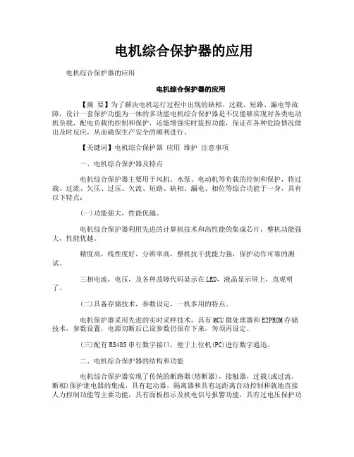
电机综合保护器的应用电机综合保护器的应用电机综合保护器的应用【摘要】为了解决电机运行过程中出现的缺相、过载、短路、漏电等故障,设计一套保护功能为一体的多功能电机综合保护器是不仅能够实现对各类电动机负载,配电负载的控制和保护,还能增强实时监控功能,保证在各种危险情况做出及时反应,从而确保生产安全的顺利进行。
【关键词】电机综合保护器应用维护注意事项一、电机综合保护器及特点电机综合保护器主要用于风机、水泵、电动机等负载的控制和保护,将过载、过流、欠压、过压、欠流、短路、缺相、漏电、相位等综合功能于一身,具有以下特点:(一)功能强大,性能优越。
电机综合保护器利用先进的计算机技术和高性能的集成芯片,整机功能强大,性能优越。
精度高,线性度好,分辨率高,整机抗干扰能力强,保护动作可靠的测试。
三相电流,电压,及各种故障代码显示在LED,液晶显示屏上,直观明了。
(二)具备存储技术,参数设定,一机多用的特点。
电机保护器采用先进的实时采样技术,具有MCU微处理器和E2PROM存储技术,参数设置,电源切断后已设参数仍保存下来,勿须再设定。
(三)配有RS485串行数字接口,便于上位机(PC)进行数字通迅。
二、电机综合保护器的结构和功能电机综合保护器实现了传统的断路器(熔断器),接触器,过载(或过流,断相)保护继电器的集成,具有起动器,隔离器和具有远距离自动控制和就地直接人力控制功能等主要功能,具有面板指示及机电信号报警功能,具有过电压保护功能,具有断相缺相保护功能,具有协调配合的时间――电流保护特性(具有反时限,定时限三段保护特性和瞬时)。
具体来说如下:(一)保护功能。
电机综合保护器除了具有通用的保护功能之外,还有自启动、通信启动和关闭,并能够根据电流,过电压、欠电压、三相电流不平衡、自启动等功能,用户可自由取舍。
(二)设置功能。
智能型电机综合保护器有设置键,数据键和移位键,设置超出范围时就会提醒用户重新设置,以避免故障。
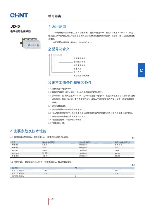
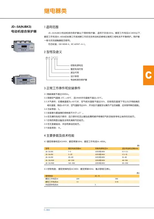
C3正常工作条件和安装条件2型号及含义1适用范围JD-5电动机综合保护器(以下简称保护器),适用于交流50Hz、额定工作电压AC380V以下,额定工作电流0.5A400A的长期工作或间断工作的交流电动机的过载和断相保护。
保护器一般与交流接触器配~合使用。
本产品符合标准GB 14048.4、IEC 60947-4-1。
JD-5电动机综合保护器3.1 海拔高度不超过2000m。
3.2 周围空气温度-15℃+55℃,且24h内平均温度不超过+50℃。
~3.3 大气条件:在 最高温度为+40℃时,空气相对湿度不超过50%,在较低的温度下可以允许有较高的相对湿度,例如+20℃时,空气湿度可达90%,并对由于温度变化偶尔产生的凝露,应采取特殊的措施。
3.4 污染等级为3级。
3.5 安装面与垂直面的倾斜度不大于±5°。
3.6 在无爆炸危险介质中,且介质中无足以腐蚀金属和破坏绝缘的气体及较多导电尘埃存在的地方。
3.7 在有防雨血设备及没有充满蒸汽的地方。
3.8 在无显著摇动、冲击和振动的地方。
3.9 安装类别:Ⅲ。
JD-5 □/□□□控制电源电压脱扣级别代号整定电流代号派生代号设计序号电动机综合保护器4主要参数及技术性能4.1 额定绝缘电压AC690V,额定频率50Hz,额定工作电流0.5A400A。
~2401.5AC-1553800.95使用类别额定工作电压(V)额定工作电流(A)约定发热电流(A)表2型号JD-5/80JD-5/80JD-5/80JD-5/400JD-5/400表1整定电流范围(A)0.55~220~2080~80200~160400~适合电动机功率(kW)0.25 2.5~110~1040~40100~80200~4.2 控制电路: 额定绝缘电压AC380V,额定频率50Hz,触点参数见表2。
控制电源电压(V)220V或380V220V或380V220V或380V220V或380V220V或380V5其它5.1 结构特点5.1.1 三相电子式,脱扣级别为10A级。

电机综合保护器的使用与调试一、工作原理经典的电机星三角启动方式主要的保护是热继电器。
若使用热继电器对大型电机作保护,就会使大电线出现断点(即进出热继电器的螺丝接线)问题,容易出现发热点和故障点。
如果不用熔断器和热继电器,而采用电机综合保护器来实现,因为电机综合保护器是穿心式,就可以减少大电线的断点,从而减少发热点和故障点,且价格比两者便宜。
使用电机综合保护器时必须注意控制线路的接线问题。
以确保正常运行。
有的电机综合保护器注明:“一定要接上负载才能正常工作,不接负载时处于缺相工作状态。
因此,综合保护器是拒绝合闸的,电动机将无法启动”。
这说明电机综合保护器内部,是依靠电流互感器,检测三相电流的有无,来判断缺相否。
在未接通电源和没有负载时。
这个闭点实际上是开点,所以没法合闸。
如型号为JD-6-300A的电机综合保护器。
接线如图1所示。
图1电路中,利用按钮的动作,错开了保护器电流检测的开闭点问题。
在时间继电器的线包前面串并接了KM01和KM02两个辅助闭点,是为了在启动结束后,关断时间继电器(因为时间继电器继续通电没有意义)。
、JD-6型电机综合保护器的原理如图2所示。
具有缺相、过载的反时限特性保护功能。
电路主要由双时基IC芯片NE556与电压电流取样环节组成比较电路、多谐振荡电路、单稳态电路等。
简述如下:1.缺相保护L1~L3.三个电流互感器取样,经三个三极管U9~U11组成的与门,在电阻R4上获得门限电位。
缺相时,只要其中一个三极管截止,在R4上形成低电位时,红色发光二极管亮,便表示缺相。
同时电容C6快速充电,NE556的左边555时基组成比较单元。
NE556的OUT1输出端⑤脚是高电位,继电器K1断开,对外的保护点也断开,从而使接触器回路跳开,电机断电而受到缺相保护。
不缺相时,在R4上形成高电位时,电容C6不能充电,NE556的OUT1输出端⑤脚变成低电位,K1吸合。
对外的保护点是闭点,电机具备启动的条件。
继电器类正泰-智慧能源解决方案提供商 l3104.1 主电路:额定绝缘电压AC690V,额定频率50Hz。
4.2 辅助电路: 额定绝缘电压AC380V,额定频率50Hz。
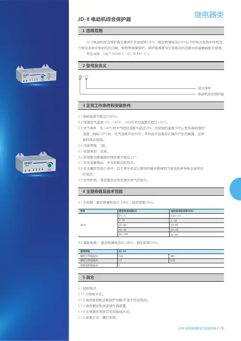
JD -8电动机综合保护器主要用于交流频率50Hz ,额定绝缘电压690V 以下的电力系统中作低压三相交流异步电动机的过载、断相等故障保护。
保护器通常与交流电动机回路中的接触器配合使用。
符合标准:GB /T 14048.4、IEC 60947-4-1。
JD-8 电动机综合保护器设计序号电动机综合保护器JD - □3.1 海拔高度不超过2000m。
3.2 周围空气温度-5℃~+40℃,24h内平均温度不超过+35℃。
3.3 大气条件:在 +40℃时大气相对湿度不超过50%,在较低的温度下可以有较高的相对湿度,例如+20℃时,空气湿度可达90%,并对由于湿度变化偶尔产生的凝露,应采取特殊的措施。
3.4 污染等级:3级。
3.5 安装类别:Ⅲ类。
3.6 安装面与垂直面的倾斜度不超过±5°。
3.7 在无显著摇动、冲击和振动的地方。
3.8 在无爆炸危险介质中,且介质中无足以腐蚀和破坏绝缘的气体及较多导电尘埃存在的地方。
3.9 在有防雨、雪设备及没有充满水蒸气的地方。
5.1 结构特点5.1.1 三相电子式。
5.1.2 具有断相和过载保护功能(不适于可逆电机)。
5.1.3 具有整定电流连续可调装置。
5.1.4 主电路采用穿芯式的接线方式。
5.1.5 安装方式:螺钉安装。
控制电器5.2 保护器在各相负载平衡时的动作特性如下,脱扣等级为30级。
5.3 接线图R2.2R3.57.1 根据使用要求选择适当型号和规格的保护器。
7.2 订货数量311 l 正泰-智慧能源解决方案提供商。

JD Series Motor Integrated ProtectorUser Manual □Перед установкой и использованием продукции внимательно прочитайте руководство по эксплуатации и храните его в надежном месте.I. Overview1.1 Scope of ApplicationJD series motor integrated protector is suitable for AC 50/60Hz and voltage 380V and below power supply circuit to form a motor control circuit together with the switch circuit such as AC contactor. When the main circuit of motor is in the abnormal working state such as phase loss, overload or stall, it can disconnect the electrical contact of switch in time and break the three-phase power supply of motor to protect the motor reliably.Standard: GB/T14048.41.2 Model DefinitionRated control supply voltage Us:AC220V;AC380VRated current: see tableCommon type if not marked;B: With an alarmA: Setting current scale calibrationDesign No.: see TableIntegrated protector for electric motor1.3 Normal Working conditions and Installation Conditions1.3.1 Ambient environment: The altitude does not exceed 2000 meters; The ambient temperature is not higher than +40°C and not lower than -5°C; the voltage change range of the rated control power supply is 85%-110% of the rated voltage; the product is installed in a medium without serious vibration or explosion hazard, and there is no enough gas or dust to cause corrosion to the metal or damage to the insulation in the medium; installed in a place where there is no rain or snow erosion.1.3.2 Vertical or horizontal installation.II. Structural Characteristics and Working PrincipleThe integrated protector for JD series electric motor designed with small division, high protection precision, reasonable structure, complete function, and convenient operation according to the motor power characteristics. The protector has protection functions for symmetrical faults (such as overload and stall) and for asymmetric fault such as phase loss; this protector adopts current sensing technology and relay output interface, and the entire series is of the core-through type. This protector features with simple structure, reliable action, convenient operation, and low cost.III. Technical parametersTechnical parameters of JD-5, JD-5B, JD-6:ModelParameterJD-5 JD-5B JD-6Rated operating current Ie range 0.5-5A 2-20A 20-80A1-80A 1-100A63-150A 63-400A100-250A 250-500ARated insulation voltage Ui AC380VRated opearting voltage Ue AC380VRated control power voltage Us AC50/60Hz AC220V AC380VUsage category Main circuit AC-3; matched auxiliary contact (body) AC-15 Housing protection grade IP40 IP50Type and qty. of aux. circuits 1 normally-closed 1 normally-open 1 normally-closed Operating voltage and operatingcurrent under the usage categoryof auxiliary circuitAC-15 Ue” AC220V Ie: 0.47ARated limit short-circuit currentmatching SCPDRT16-00, 6ATrip grade 10AOverload proteciton characteristics The actual operating current of motor is 1.05 times rated operating current, the action protection time of protector is greater than or equals to 2h; when the actual operating current rises to 1.2 times, the action protection time of protector is less than 2h; when the acutal operating current rises to 1.5 times, the action protection time of protector is less than 2 minutes; when the actual operating current of motor is 7.2 times rated operating current, the action protection time of protector is greater than 2s, and less than or equals to 10s.Phase loss time Loss of any phase in three phases ≤ 3sContact capacity AC380V, 3A: AC220V, 5A (resistive)Electrical life: ≥10 x 104 timesMechanical life ≥10 x 104 timesInstallation method Device type (with TH35 mounting rail or screw fixed installation used)Technical parameters of JD-5A, JD-6A:ModelParameterJD-5A JD-6ARated operating current Ie range0.5A-5A 2A-20A 2A-10A8A-40A 10A-100A 20A-10020A-100A (5 and 6 breaking)100A-400A (5 and 6 making)Rated insulation voltage Ui AC380VRated opearting voltage Ue AC380VRated control power voltage Us AC50/60Hz AC220V AC380VUsage category Main circuit AC-3; matched auxiliary contact (body) AC-15 Housing protection grade IP40 IP50Type and qty. of aux. circuits 1 normally-closed 1 normally-open 1 normally-closed Operating voltage and operatingcurrent under the usagecategory of auxiliary circuitAC-15 Ue: AC220V Ie: 0.47ARated limit short-circuit currentmatching SCPDRT16-00, 6AOverload time Trip grade 1.2 times 1.5 times 7.2 times10 Tp<2h Tp≤4min 4<Tp≤10sPhase loss time Loss of any phase in three phases ≤ 6sContact capacity AC380V, 3A: AC220V, 5A (resistive)Reset Power outage reset and not less than 300s Electrical life: ≥10 x 104 timesMechanical life ≥10 x 104 timesInstallation method Device type (with TH35 mounting rail or screw fixed installation used) Note: 1. When the rated current of the motor is lower 2A for JD-5A, wind the Phase A and Phase C more turns (holes on both sides of protector) to ensure that the core-through current is not below 2A.2. When the setting current of the protector of JD-6A motor is ranged from 20A to 100A, the pins 5 and 6 of protector are disconnected; when the rated current of motor is greater than 100A, the pins 5 and 6 of protector are connected through a wire, and the setting value shown on the scale dial is 100 to 400A.JD-5A, JD-5, JD-5B Performance Difference TableModelFunctionJD-5A JD-6AJD-5JD-5B JD-6Phase loss proteciton The working power supply and three-phase current can be turned on asynchronously, suitable forstar-delta conversion, with phaseloss protection not provided for non-load at the moment of conversion.The working power supply andthree-phase current shall be turned on synchronously, not suitable for star-delta conversion, with phase loss protection provided for non-load at the moment of conversion.Setting modeCalbricated scale; static setting is performed according to the ratedcurrent of motor for accurate, intuitive and convenient operation. Setting the current can be performed only when the motor is running without calbricated scale. Overload characteristics With motor start timeout protection,and with start time adjustment. The overload inverse limit range is small, unable to adjust the trip grade.IV. Outline and Installation DimensionsJD-5. JD-5A, JD-5B Outline and Installation Dimension DrawingJD-6 Outline and Installation Dimension DrawingV. Installation and Operation InstructionsJD-5, JD-5B, and JD-6 installation and operation instructions:1. Please read the user manual carefully and connect the wire correctly according to the wiring diagram.2. Terminals 1 and 2 are the working power input terminals of the protector; JD-5 and JD-5B: 3 and 4 are normally closed contacts at the output control terminal; JD-6: 5 and 6 are the normally closed contacts at the output control terminal, and 4 and 5 is the normally open contacts at the output control terminal. For wiring method, refer to the wiring diagram; the three wires of output terminal of AC contactor pass through three white wire holes H1, H2, and H3 of the protector respectively to connect with the inlet wires of motor. (Refer to the wiring diagram).3. Turn the two adjusting knobs on the protector panel clockwise to the maximum, and turn on the power supply after confirming that the wire is connected properly. Press the Start button and run the motor (the green light is on and the phase loss yellow light is not on, and the overload red/green light is on when normal operation). When the product is running normally, turn the current adjusting knob counterclockwise until the overload indicator flickers, and then fine adjust it clockwise to the critical position where the overload lamp does not flicker; observe it for about 3 minutes. During this period, the current or motor and load are normal, and the overload indicator does not flicker, and then turn the delay button back counter clockwise to the position greater than the motor start time (longer is preferred).4. When the motor works normally, the overload light is not on, and the motor is applied with load manually, andat this time, the overload lamp will flicker, so the entire debugging process is completed.Protector ProtectorNote: AQ: Start Note: QA: StartTA: Stop TA: StopKM: AC contactor 220V KM: AC contactor 380V(JD-5(B) and BHQ-S-J have the same wiring) (JD-5(B) and BHQ-S-J have the same wiring) JD-5, JD-5B: AC220V JD-5, JD-5B: AC380VWiring diagram Wiring diagramProtectorProtectorNote: AQ: Start Note: QA: StartTA: Stop TA: StopKM: AC contactor 220V KM: AC contactor 380VJD-5A: AC220V JD-5A: AC380VWiring diagram Wiring diagramNote: AQ: Start Note: QA: StartTA: Stop TA: StopKM: AC contactor 220V KM: AC contactor 380VJD-6: AC220V JD-6: AC380VWiring diagram Wiring diagramSpecification conversion Specification conversion Note: AQ: Start Note: QA: StartTA: Stop TA: StopKM: AC contactor 220V KM: AC contactor 380VJD-6A: AC220V JD-6A: AC380VWiring diagram Wiring diagramVI. PrecautionsJD-5A:1. Correct wire according to the wiring diagram.2. Adjust the current setting potentiometer to align the pointer with the corresponding calibration scale according to the rated current marked on the nameplate of the motor.3. Start the motor, and the overload indicator is on. After startup, the overload indicator shall be off during normal operation, so the adjustment process is completed.JD-5 and JD-5B:1. When debugging the current knob, it shall be carried out when a change of the rated working voltage is less than ±5%.2. For motors with a line current of less than 6A, the three-phase power line should be wound onto the white wire hole of the protection by considering that the non-load line current of motor is smaller. Technical characteristics should be met.3. Due to the internal structure relationship, the overcurrent adjustment scale is not linear, and the actual debugging shall prevail.4. Regularly check the performance of the protector, such as phase loss test and overload test.5. It is strictly forbidden to increase the reading on the current potentiometer of the protector when the current and motor or load are not normal, otherwise the motor may be easily burnt.6A and above 3A~6A, H2 1A~3A,First wire winding Second wire winding H1, H2, H3Third wire windingJD-5 and JD-5B wire winding diagramJD-6A:1. Correct wire according to the wiring diagram.2. Adjust the current setting potentiometer to align the pointer with the corresponding calibration scale according to the rated current on the nameplate of the motor. Wind the wires three turns for 2A and below current A and C phases.3. Start the motor, and the overload indicator is on. After startup, the overload indicator shall be off during normal operation, and the adjustment process is completed.JD-6:1. When debugging the current knob, it shall be carried out when a change of the rated working voltage is less than ±5%.2. For motors with a line current of less than 63A, the three-phase power line should be wound onto the white wire hole of the protection by considering that the non-load line current of motor is smaller. Technical characteristics should be met.3. Due to the internal structure relationship, the overcurrent adjustment scale is not linear, and the actual debugging shall prevail.4. Regularly check the performance of the protector, such as phase loss test and overload test.5. It is strictly forbidden to increase the reading on the current potentiometer of the protector when the current and motor or load are not normal, otherwise the motor may be easily burnt.6. For equipment that may cause major economic losses or personal safety, make sure that the technical characteristics and performance values have sufficient margin in design, and safety measures such as doublecircuit protection should be adopted.VII. Common Faults and Solutions1.If the motor stops during normal operation, carefully check the motor for phase loss or overload; first check whether the motor temperature is very high, and this may be overload stop due to temperature rise; if there is no temperature rise, the line phase loss may occur, causing trip, and check whether the three-phase power supply works normally, whether the moving and fixed contacts of AC contactor have good contact, whether three power lines of motor are loose; if the motor still fails to start when all are in the normal state, carefully check whether the connecting screws of self-lock contacts of AC contactor and of normally-closed contacts of protector are loose, and then start and run the motor only after all faults are eliminated. Do not start the motor mandatorily if any fault is not solved to prevent accidents.2.The protector, motor and load switch (such as contactor) shall be used together, and their power supplies are connected simultaneously. If failed to connect the power supply simultaneously, the phase loss failure of protector will occur, and the motor cannot start normally.3.In case of failure of product, first disconnect the power supply, and find out the fault cause; operate the product according to the installation instruction after checking the line works normally.4.For product with poor quality, please contact the local dealer or our company.VIII. Transportation and StorageThe product is not affected by rain or snow during storage and transportation, and cannot be extruded, and should be put in well-vented place during storage; the relative humidity does not exceed 90% at (25°C± 5°C). The lower limit of temperature is -25°C and the upper limit is +55°C.IX. Unpacking and InspectionUnpack the outer paper carton and check that there is a user manual in the packing box.V. Ordering NoticeJD-5 and JD-5B products have the exactly same performance except that the JD-5B has one more failure alarm buzzer compared with the JD-5. JD-5 current is 1-80A; 0.5-5A; 2-20A; 20-80A; the JD-5A current is 2-10A; 8-40A; 20-100A;The JD-6 current is 63-400A, 63-150A, 100-250A, 200-500A; when selecting the model, note that the power of motor is consistent with that of the protector.When ordering, please specify the model and specification of the product. If you have special requirements, please contact the manufacturer.XI. Company CommitmentUnder the condition that users follow the use and storage conditions and the product are well sealed, within 24 months from the production date, our company will provide repair and replacement service free of charge for any damage or abnormal operation due to poor manufacture quality. A paid repair will be provided if the warranty period expires. For any damage due to one of the following situations, a paid repair will be given even if within the warranty period:(1)Improper operation, maintenance, or storage;(2)Modified without permission or improper repair;(3)Damage due to falling off or caused during installation after purchase;(4)Force majeure such as earthquakes, fires, lightning strikes, abnormal voltages, and secondary disasters;(5) The electrical life of the product exceeds 100,000 times; the mechanical life is more than one million times. If you have any question, please contact the dealer or our company’s customer service department.Customer service hotline:400-826-8008Certificate DELIXI ELECTRIC LTD Name: Motor Integrated ProtectorModel: JD SeriesThis product complies with the GB/T 14048.4 standard, and passes the inspection and is allowed to be shipped. Inspector: Check 01Production date: See label on inner boxDELIXI ELECTRIC LTDAddress: Delixi High-Tech Industrial Park, Liushi Town, Leqing City, Zhejiang P/C: 325604 Tel: (86-577) 6177 8888Fax: (86-577) 6177 8000Customer Service hotline: 400-826-8008The first edition of this manual was issued on August 2021.。
JD一6的电机保护器五个接线柱的接法图本文主要是关于JD一6的电机保护器的相关介绍,并着重对JD一6的电机保护器的接线图进行了详尽的阐述。
电机保护器电机保护器的作用是给电机全面的保护,在电机出现过载、过流、缺相、堵转、短路、过压、欠压、漏电、三相不平衡、过热、轴承磨损、定转子偏心时,予以报警或保护的装置。
选型市场上电机保护产品未有统一标准,型号规格五花八门。
制造厂商为了满足用户不同的使用需求派生出很多的系列产品,种类繁多,给广大用户选型带来诸多不便;用户在选型时应充分考虑电机保护实际需求,合理选择保护功能和保护方式,才能达到良好的保护效果,达到提高设备运行可靠性,减少非计划停车,减少事故损失的目的。
(一)与选型有关的条件1、电机参数:要先了解电机的规格型号、功能特性、防护型式、额定电压、额定电流、额定功率、电源频率、绝缘等级等。
这些内容基本能给用户正确选择保护器提供了参考依据。
2、环境条件:主要指常温、高温、高寒、腐蚀度、震动度、风沙、海拔、电磁污染等。
3、电机用途:主要指拖动机械设备要求特点,如风机、水泵、空压机、车床、油田抽油机等不同负载机械特性。
4、控制方式:控制模式有手动、自动、就地控制、远程控制、单机独立运行、生产线集中控制等情况。
启动方式有直接、降压、星角、频敏变阻器、变频器、软起动等。
5、其他方面:用户对现场生产监护管理情况,非正常性的停机对生产影响的严重程度等。
与保护器的选用相关的因素还有很多,如安装位置、电源情况、配电系统情况等;还要考虑是对新购电机配置保护,还是对电机保护升级,还是对事故电机保护的完善等;还要考虑电机保护方式改变的难度和对生产影响程度;需根据现场实际工作条件综合考虑保护器的选型和调整。
(二)电机保护器的常见类型1、热继电器:普通小容量交流电机,工作条件良好,不存在频繁启动等恶劣工况的场合;由于精度较差,可靠性不能保证,不推荐使用。
2、电子型:检测三相电流值,整定电流值采用电位器或拔码开关,电路一般采用模拟式,采用反时限或定时限工作特性。
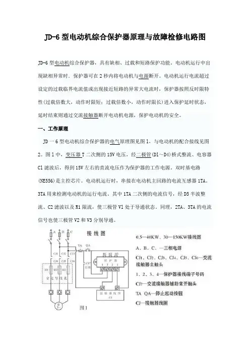
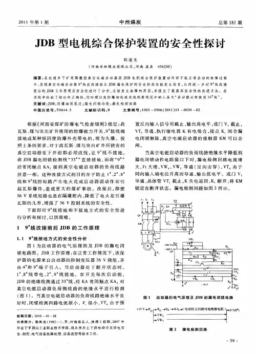
JD-6型电动机综合保护器原理与故障检修电路图JD-6型电动机综合保护器,具有缺相、过载和短路保护功能。
电动机运行中出现缺相异常时.保护器可在2秒内将电动机与电源断开。
电动机运行电流超过设定的过载临界电流值或出现接近短路的异常大电流时,保护器按照反时限特性(过载倍数大,动作时限短;过载倍数小,动作时限长)进入保护延时状态,延时结束则通过交流接触器断开电动机电源,保护电动机的安全。
一、工作原理JD一6型电动机综合保护器的电气原理图见图l,与电动机的配合接线见图2。
图l中,变压器T二次侧的15V电压,经二极管(Dl~D4)桥式整流、电容器Cl 滤波后,得到15V左右的直流电压作为保护器的工作电源。
双时基电路(NE556)是主控芯片。
电动机运行时,串接在电动机主回路的电流互感器1TA。
3TA用来检测电动机的运行电流。
其中1TA二次侧的电流信号,经D5半波整流、C2滤波以及R1限流,使三极管Vl处于导通状态。
同理,2TA、3TA的电流信号也使三极管V2和V3分别导通。
1.缺相保护电动机的缺相保护由NE556的一个时基电路即⑧脚一13脚内外电路实施。
电动机启动运行后.电流互感器1TA-3TA的一、二次回路均有电流,三极管V1-V3均导通,电容器Cl正极的15V电压经三极管Vl、V2、V3和电阻R12到地(此时R12两端电压约为14.7V)。
同时电容器C6经二极管D16和R12充电,充电终止时,NE556的12脚、R12端和⑧脚(S2端)电压约为14V。
根据时基电路的工作原理,此时其输出端⑨脚(V02端)被复位为低电平.继电器K线圈两端无电压不动作.常闭触点维持在闭合状态,由图2可见,已启动的电动机可以正常运行。
如果电网缺相,或有熔断器FU熔断,相应相别的电流互感器电流为零.由该电流信号控制的三极管截止,电阻R12上的电压发生变化,其数值由缺相指示灯LED3、电阻R11和R12决定:缺相时LED3点亮(其两端电压约为2V)。
JD6L(JD46)(250A)鉴相鉴幅漏电继电器一,概述JD46漏电继电器与交流接触器或断路器组合成漏电保护装置,主要功能是对有致命危险和用电设备提供间接接触保护,该产品适用于中性点直接接地的380V/220V低压配电系统。
二,产品特点本产品除符合JB8756-98、GB6829—95以外,还有以下特点:1,能在线路复杂,泄漏较大的线路上正常运行。
2,抗干扰性极强,雷电,大电动机不误动作。
3,自动数字显示漏电毫安值,判别线断故障,了解线路漏电情况,直观简单方便。
4,漏电动作值范围大(可调),加大了使用的适应性。
5,无声节能运行,对配接的接触器线圈工作电压220V、380V通用,消除噪声,节电率85%以上(节能型)。
6,开机具有显示最后一次跳闸电流值,并且开机延时1秒左右能自动检测当前线路情况。
7,运行中可以直观地分别看出三相当前在线电流的大小,能迅速达到监测线路运行情况。
8,分断时间可以0.1s—0.5秒之间随意调节。
9,漏电整定值可以在100mA—800mA之间以100mA进制随意调节,并且可以在特殊情况下退出漏电保护功能(漏电无限大,不提倡使用)。
10,在跳闸延时10—20秒,并二次跳闸闭锁后会有连续报警声一直报警!让维护人员在远处就知道保护器已跳闸并闭锁。
11,具有一次跳闸检测,二次跳闸闭锁功能。
跳闸闭锁后显示当前所在的故障相位(L-A、L-b、L-C)大大减小安装维护员的工作量。
12,在无保护功能情况下,开机时有20—30秒的长报警音报警,并且黄色指示灯一直闪烁,提配安装人员继电器处在无保护功能状态。
13,继电器系统留有空间,方便产品以后功能升级使用.14,自动保存用户调整好的工作电流和分断时间整定值,并且保存最后一次跳闸电流值,方便用户查询(停电或重启)。
三、产品功能及功能介绍1,漏电电流整定值选择:d-0=0mA; d-1=100mA; d-2=200mA; d-3=300mA;d-4=400mA; d-5=500mA; d-6=600mA; d-7=700mA; d-8=800mA;使用说明:开机正常运行后,按‘功能’键一次,数码管显示‘d-x’(x 代表0—8之间的数字,可能是开机的属性值0,也可能是用户或出厂已调整好的数字,下文出现的x都代表数字并且闪烁),然后按’移位/查询’按钮,从0—8之间选择一个数字作为当前的保护动作电流整定值。
CJD-8电动机综合保护器主要用于交流频率50Hz,额定绝缘电压690V以下的电力系统中作低压三相交流异步电动机的过载、断相等故障保护。
保护器通常与交流电动机回路中的接触器配合使用。
符合标准:GB 14048.4、IEC 60947-4-1。
JD-8电动机综合保护器3.1 海拔高度不超过2000m。
3.2 周围空气温度-5℃~+40℃,24h内平均温度不超过+35℃。
3.3 大气条件:在 +40℃时大气相对湿度不超过50%,在较低的温度下可以有较高的相对湿度,例如+20℃ 时,空气湿度可达90%,并对由于湿度变化偶尔产生的凝露,应采取特殊的措施。
3.4 污染等级为3级。
3.5 安装类别为Ⅲ类。
3.6 安装面与垂直面的倾斜度不超过±5°。
3.7 在无显著摇动、冲击和振动的地方。
3.8 在无爆炸危险介质中,且介质中无足以腐蚀和破坏绝缘的气体及较多导电尘埃存在的地方。
3.9 在有防雨、雪设备及没有充满水蒸气的地方。
4.1 主电路:额定绝缘电压AC690V,额定频率50Hz。
2201.5AC-1553800.95使用类别 额定工作电压(V)额定工作电流(A)约定发热电流(A)型号JD-8/5JD-8/20JD-8/80整定电流范围(A)0.5-52-2020-80适合电动机功率(kW)0.25-2.51-1010-404.2 辅助电路: 额定绝缘电压AC380V,额定频率50Hz。
1 适用范围2 型号及含义3 正常工作条件和安装条件4 主要参数及技术性能控制触点类型 整定电流代号 设计序号 电动机综合保护器JD - □ / □ □5 其它5.1 结构特点5.1.1 三相电子式。
5.1.2 具有断相和过载保护功能(不适于可逆电机)。
5.1.3 具有整定电流连续可调装置。
5.1.4 主电路采用穿芯式的接线方式。
5.1.5 安装方式:螺钉安装。
5.2 保护器在各相负载平衡时的动作特性。
CJD-8电动机综合保护器(以下简称保护器)主要用于交流频率50Hz,额定绝缘电压690V以下的电力系统中作低压三相交流异步电动机的过载、断相等故障保护。
保护器通常与交流电动机回路中的接触器配合使用。
本产品符合标准GB 14048.4、IEC 60947-4-1。
JD-8电动机综合保护器3.1 海拔高度不超过2000m。
3.2 周围空气温度-5℃+40℃,24h内平均温度不超过+35℃。
~3.3 大气条件:在 +40℃时大气相对湿度不超过50%,在较低的温度下可以有较高的相对湿度,最湿月 的月平均最大相对湿度不超过90%,该月的月平均最低温度不超过+25℃,并考虑到因温度变化发生 在产品表面的凝露。
3.4 污染等级为3级。
3.5 安装类别为Ⅲ类。
3.6 安装面与垂直面的倾斜度不超过±5°。
3.7 在无显著摇动、冲击和振动的地方。
3.8 在无爆炸危险介质中,且介质中无呈现腐蚀和破坏绝缘存在的地方的气体及较多导电尘埃。
3.9 在有防雨、雪设备及没有充满水蒸气的地方。
JD- □/□ □控制触点类型 整定电流代号 设计序号 电动机综合保护器4.1 主电路:额定绝缘电压AC690V,额定频率50Hz。
2400.75AC-1513800.47使用类别 额定工作电压(V)额定工作电流(A)约定发热电流(A)型号JD-8/5JD-8/20JD-8/80整定电流范围(A)0.5-52-2020-80适合电动机功率(kW)0.25-2.51-1010-404.2 辅助电路: 额定绝缘电压AC380V,额定频率50Hz,使用类别、额定工作电压、额定工作电流和约 定发热电流。
1适用范围2型号及含义3正常工作条件和安装条件4主要参数及技术性能5其它5.1 结构特点5.1.1 三相电子式。
5.1.2 具有断相和过载保护功能(不适于可逆电机)。
5.1.3 具有整定电流连续可调装置。
5.1.4 主电路采用穿芯式的接线方式。
六、操作注意事项十、订货须知十一、公司承诺在用户遵守、使用、保管条件及产品封印完好的前提下,自产品生产日期起二十四个月内,产品如因制造质量问题发生损坏或不能正常使用的,本公司负责无偿修理或更换。
超过保修期的,需有偿修理。
但因下述情形引起损坏的,即使在保修期内亦做有偿修理:(1) 因使用、维护、保管不当的;(2) 自行改装、不适当修理的;(3) 购买后由于摔落及安装过程中发生损坏的;(4) 地震、火灾、雷击、异常电压及二次灾害等不可抗 力的;(5) 产品使用电寿命超过10万次;机械寿命超过100万次 的。
如有问题请与经销商或本公司客户服务部门联系。
客户服务热线400-826-8008地址: 浙江省乐清市柳市镇电器城3单元 邮编: 325604电话: (86-577)6177 8888传真: (86-577)6177 8000客服热线: 400-826-8008本使用说明书自2018年11月 第一版生产厂:一、概述1.1 适用范围JD系列电动机综合保护器,适用于交流50/60Hz,电压380V及以下的供电电路中与交流接触器等开关电路组成电动机控制电路。
当电动机的主电路出现断相、过载、堵转等非正常工作状态时,能及时断开开关电器触头,分断电动机三相电源,可靠地保护电动机。
1.2 型号定义额定控制电源电压Us : AC220V ; AC380V 额定电流:见表无标注为普通型; B :自带报警;A :整定电流刻度标定设计序号:见表电动机综合保护器二、结构特征与工作原理JD -5A 、JD -6A 技术参数:过载时间JD 5A-2A-10A 8A 40A20A-100-JD 6A-20A ~400A (5、6断开电流规格20A ~100A ;5、6接通电流规格100A ~400A )三相任意一相断相≤6s 断电复位且不小于300s脱扣级别10A 102030在电流整定值倍数下的脱扣时间Tp1.2倍Tp <2h Tp <2h Tp <2h Tp <2h1.5倍Tp ≤2min Tp ≤4min Tp ≤8min Tp ≤12min7.2倍2s <Tp ≤10s 4s <Tp ≤10s 6s <Tp ≤20s 9s <Tp ≤30sJD-5A、JD-5JD-5B 性能差异表、及JD -6、JD -6A 功能型号断相保护整定方式过载特性JD-5A JD-5、JD-5B 、JD-6工作电源和三相电流可异步接通供给,适合星-三角转换,在转换瞬间空载不会断相保护。
1、概述JD6-Ⅲ剩余电流保护器(以下简称保护器)与低压断路器或交流接触器组合成剩余电流动作保护装置。
用来对线路进行接地故障保护,防止由于接地故障电流引起的设备事故或电气火灾,可用来对人身触电危险提供间接接触保护,适用于配电变压器中性点直接接地(380V/220V)的低压电网,以提高电网安全运行能力。
JD6-Ⅲ是本企业研究开发的新产品,采用单片微处理器控制技术,具有较理想的延时特性,分断时间有0.5/0.3s两档,任用户选调,并有一次重合闸功能。
适应各种复杂的农村电网和多变的气候环境,投运率高,特别适用于电网多级保护中的一级总保护或二级分支保护,产品符合GB13955-2005农村电力技术规程对分断电流和分断时间的级差要求。
2、产品特点2.1分断时间分类为S型,分断时间0.5/0.3s两档可调。
在2I△n、5 I△n时分断时间呈反时限特性。
2.2 设置多种接线类别(见型号说明),可配接多种类别的主开关,互感器通用。
2.3保护器开机或停电后来电,有一次试送电(接线类别为D、E或用户特别要求除外),保护器分闸20~30秒后自动重合闸投入运行。
2.4具有一次自动重合闸功能,即线路发生漏电故障分闸后,延时20~30秒后自动重合闸,如果在重合闸后5秒内再次发生漏电故障跳闸,保护器则自锁。
2.5剩余电流动作值固定分档可调,用户可根据线路状况或天气环境等情况选择适当的动作值。
面板上有电流表显示线路的剩余电流矢量值。
2.6标准型对配接CJ10或CJ20交流接触器有节能无声运行功能,接触器线圈220V、380V通用(额定电流63A~400A),接线方便,可延长接触器线圈寿命。
有节能效果,1至2年的节电费就可以收回投资。
2.7面板功能及外形安装尺寸见图13、技术参数3.1额定电压380V3.2额定频率50HZ3.3额定主电路电流63A~400A3.4额定剩余动作电流0.1 A、0.3A、0.5A可调3.5额定剩余不动作电流0.05 A、0.15A、0.25A 3.6额定分断时间<0.3s(0.5s)可调3.7额定辅助电压AC 220V3.8保护器输出接点容量AC 220V 3A3.9延时重合闸时间20s~30s3.10动作特性分类AC型3.11分断时间分类S型3.12熔丝容量(配接小环)5A熔丝容量(配接中环)8A熔丝容量(配接大环)10A3.13本产品符合JB 8756-19981-挂板,2-保险丝座(背面),3-互感器插座(背面),4-漏电电流表,5-状态指示灯,6-红色跳闸指示灯,7-剩余电流动作值调节开关,8-分断时间调节,9-电源开关,11-接线端子,12-零序互感器(小环Ф44、中环Ф60、大环Ф83mm),13-插头14-插头防脱扣互感器的尺寸:mm4、使用环境条件:4.1环境温度-5℃~+40℃4.2 相对空气湿度:最高温度+40℃时,≤50%;月平均≤+25℃时,≤90%4.3 海拔高度≤2000M4.4 污染等级 3级4.5 安装类别(过电压类别)Ⅲ类5、安装和试验5.1 零序互感器安装位置尽量远离交流接触器、电流(压)互感器;大电流母排;补偿起动器等强磁场(上下、左右、前后距离至少20厘米以上)。