
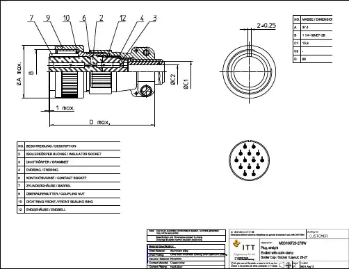
MS3106F20-27SW;中文规格书,Datasheet资料
- 格式:pdf
- 大小:255.44 KB
- 文档页数:2

Advanced AMS3106
Monolithic
500mA LOW DROPOUT VOLTAGE REGULATOR
Systems
RoHS compliant
FEATURES APPLICATIONS
• 0.6V to 6V in 100mV increments Voltages Available • Battery Powered Systems
• Active High On/Off Control • Cellular Phones
• Output Current of 500mA • Cordless Telephones
• Quiescent Current of <1µA when in Shutdown • Portable (Notebook) Computers
• Low Dropout Voltage of 250mV at 500mA • Portable Instrumentation
• Wide Supply Voltage Range 1.5V to 15V • Portable Consumer Equipment
• Short Circuit and Thermal Protection • Personal Communication Equipment
• Power Good function option • Radio Control Systems
• Ceramic Output Capacitor OK • Low Voltage Systems
• Reference bypass for low noise • MP3 Player
GENERAL DESCRIPTION
The AMS3106 is a 500mA low dropout fixed voltage regulator, featuring an internal electronic switch controlled by TTL or

Dimensions are shown in inches (millimeters).
Dimensions subject to -C-5015 Connectors MS-E/F/R/ER
How to OrderITT Cannon is the foremost manufacturer of MS andMS type connectors with the widest range ofconnector styles, sizes and variations in the indus-try. These connectors utilize the finest materials,which, along with precision manufacturing and rigidquality control, assure ITT Cannon customers of thefinest quality connectors.These circular connectors were originally designedfor aircraft, but are now widely used in many otherfields. They are particularly suitable for commercialapplications requiring low cost and high reliability.ENVIRONMENTAL RESISTANT MS-E, MS-F,MS-R AND F80 (Solder/Crimp Termination)MS-E, MS-F and MS-R are similar to MS-A andMS-B connectors but have resilient insulators andwire sealing grommets for extreme environmentalconditions and high altitude sealing. MS-E's andMS-F's have a mechanical cable clamp; the MS-Rhas a shorter, lighter weight endbell without thecable clamp. Both the MS-F and MS-R have 0 ringsto supplement the interfacial seal. Shells are alumi-num alloy. Contacts are siliver plated copper alloy.The F80 modification (crimp contact termination) isavailable in E, R, F and BFR styles with resilientinsulators.In the latest revision of MIL-C-5015, a new class ofenvironment-resistant connectors was added. Thisnew class F connector supersedes the previousclass E connector. The MS3106F is identical to theMS3106E except that the MS3106F has an "0"ring under the coupling nut. The class E will still beavailable upon request for exitsting programs, andupon ordering will also bear the E nomenclature onthe shell.MS-F and MS-R connectors are designed to operatein the extreme environmental conditions of highaltitude filight and must be completely sealed towithstand moisture, condensation, vibration, coronaand flashover caused by high altitude environments.They have resilient grommet with internal restric-tions in the wire cavities which act as 0 ringsaround the wires. This allows the wires to slide thruthe grommet with a minimum of friction, yet whenthe ferrule is seated and the endbell tightened itprovides a perfect wire seal thru a wide variety ofwire diameters. This seal at the rear, plus theinterfacial seal at the front, effects a completelyenvironment-resistant asssembly when the plug ismated to and F or R receptacle. Sockets are of theclosed-entry type.The temperature range for this connector is -55˚C(-67˚F) to +125˚C (+257˚F) and meets therequirements of MIL-C-5015.The F80 modification (crimp contact termination) isavialable in resilient insulators in the E, R, F, andBFR styles, creating a large selection of insertassemblies and hardware. Components are identicalto the MS-5015 except that the contacts aremodified for crimp termination providing and in-expensive crimp contact connector with the provenreliability of and complete intermateability with theMS-5015 series. See page 187 for assembly in-structions. Cable clamps have been integrally de-signed with the endbell on MS-E and MS-F connec-tors. Class R is without the cable clamp.POTTING ER CONNECTORS (Solder ContactTermination)These lightweight potting connectors provide re-sistance to salt water, fuels, etc., and will with-stand the effects of high vibration. 3100 and 3106connectors with plastic potting cups and resilientinserts meet the requirements of MS3103 andMS25183. Contacts are silver plated copper orbrass. ER insulators are resilient; shells are alumi-num alloy. A 90˚ plug (3108ER) is also available.ACCESSORIESAccessories to fit MS connectors include junctionshells, protective caps, dummy or stowage recepta-cles, cable clamps, telescoping bushings.PREFIXCAMS31063106RR20202727PPWW*---

Dimensions are shown in inches (millimeters).Dimensions subject to -C-5015 Firewall Connectors MS-K
Performance and Material SpecificationsMATERIALS
SERIES PREFIXSERIES PREFIXMSShell - SteelShell - Olive drab over cadmium plateShell Size - In sixteenths of an inchCoupling - ThreadedContact Arrangements - See pages 216-217Number of Contacts - 1 thru 37Contacts - Silver plateInsulator - Glass-filled epoxy or glass-filled melamine or melamine glass cloth laminateContacts - Copper alloy
8S to 36See pages 216-217P for pin; S for socketSee pages 202-204K per MIL-C-5015SHELL SIZECONTACT ARRANGEMENTCONTACT TYPESHELL STYLECLASSMS3106K368PSHELL STYLECLASSCONTACT TYPECONTACT ARRANGEMENTSHELL SIZEMS3100K
Sizes 8S to 18 have junction shell
• Receptacles in size 10SL are available with pin inserts only.* Add contact arrangment. See pages 216-217.† Add contact type:P - pin; S - socket.Sizes 20 to 36 have endbellATHREADBMLKW
GBPC 12, 15, 25, 35 SERIES — Bridge Rectifiers (Glass Passivated)
© 2010 Fairchild Semiconductor Corporation
GBPC 12, 15, 25, 35 SERIES Rev. C51 July 2010
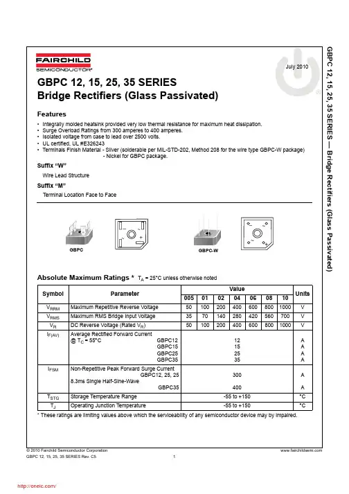
GBPC 12, 15, 25, 35 SERIES
Bridge Rectifiers (Glass Passivated)
Features
•Integrally molded heatsink provided very low thermal resistance for maximum heat dissipation.
•Surge Overload Ratings from 300 amperes to 400 amperes.
•Isolated voltage from case to lead over 2500 volts.
•UL certified, UL #E326243
•Terminals Finish Material - Silver (solderable per MIL-STD-202, Method 208 for the wire type GBPC-W package)
- Nickel for GBPC package.
Suffix “W”
Wire Lead Structure
Suffix “M”
Terminal Location Face to Face
Absolute Maximum Ratings * T
A = 25°C unless otherwise noted
* These ratings are limiting values above which the serviceability of any semiconductor device may by impaired.SymbolParameterValue