QLY9096使用说明书
- 格式:doc
- 大小:156.50 KB
- 文档页数:15

风电项目风机吊装施工资源配置方案1.1工器具及材料
1.2主要施工机械
吊车选择:
为确保安全,又避免不必要的浪费,吊车的选择非常重要,维斯塔斯2.0MW最重部件机舱70吨,为该工程中安装位置较高的部件,叶轮为外形最大且安装位置最高的部件总吨数 43.1吨,安装高度78米。
设备的吊装重量按下式进行计算:
G设备吊装重量=(G0+G1+G2)×K1
其中:
G设备吊装重量——吊车吊装时的实际载荷,单位:t;
G0——设备的实际重量,单位:t;
G1——吊车吊钩的重量,单位:t;
G2——吊索具的重量,单位:t;
K1——不均衡载荷系数,取1.1;
吊车的选择:
2.0MW机舱部件重70吨,安装高度78米,机舱吊带重量约0.2吨;
G MWT机舱吊装重量=(70+3+0.2)×1.1=80.52(吨)
通过计算及综合分析:QLY9096型轮胎式起重机,重型固定副臂模式,主臂(立杆)长36米,副臂长66米,钩头极限起升高度96米,15.6米工作半径时额定起重量90吨,可满足吊装要求。
QLY9096型轮胎式起重机性能表见后附图。
说明:1、本技术方案以QLY9096型轮胎式起重机为主吊进行施工
2、350吨汽车吊进行设备的卸车及辅助工作
3、70吨汽车吊辅助吊装
1.3劳动力计划
1.4施工总体安排
电气工程按“先设备后电缆、先安装后调试”的原则。
同一工种可以采取平行流水作业的方法组织施工,小工序之间则为相互交错而成流水作业。
设备安装按照线路进行安装,按施工工序计划安排人员、工机具、材料进场。

Operator’s ManualMonogram SeriesDUAL DESK CHARGERBML 161 54/1,3 (120 V AC)BML 161 54/2,4 (230 V AC)ENOTICE!This manual covers Ericsson and General Electric products sold by Ericsson Inc.NOTERepairs to this equipment should be made only by an authorized service technician or facility designated by the supplier. Any repairs, alterations or substitution of recommended parts made by the user to this equipment not approved by the manufacturer could void the user’s authority to operate the equipment in addition to the manufacturer’s warranty.This manual is published by Ericsson Inc., without any warranty. Improvements and changes to this manual necessitated by typographical errors, inaccuracies of current information, or improvements to programs and/or equipment, may be made by Ericsson Inc., at any time and without notice. Such changes will be incorporated into new editions of this manual. No part of this manual may be reproduced or transmitted in any form or by any means, electronic or mechanical, including photocopying and recording, for any purpose, without the express written permission of Ericsson Inc.Copyright © June 1995, Ericsson Inc.2IMPORTANT SAFETYINFORMATION1.SAVE THIS MANUAL - It contains important safety and operatinginstructions for MONOGRAM Series Dual Desk Charger.2.Before using the battery charger, read all instructions and cautionarymarkings on (1) the battery charger, (2) the battery, and (3) the product using the battery.3.CAUTION - T o reduce the risk of injury, charge only Ericsson batterypacks. Charging any other battery pack or batteries may cause the battery to burst and cause personal injury or damage.4.Do not expose charger to rain or snow.5.Do not use auxiliary equipment not recommended or sold by themanufacturer. T o do so may result in a risk of fire, electric shock, or injury to persons.6 T o reduce risk of damage to electric plug and cord, pull by the plugrather than the cord when disconnecting the charger.7.Make sure the cord is located so that it will not be stepped on, trippedover, or otherwise subjected to damage or stress.8.An extension cord should not be used unless absolutely necessary.Use of an improper extension cord could result in a risk of fire and electric shock. If an extension cord must be used, make sure:a.That pins on the plug of the extension cord are the same number,size, and shape as those on the charger’s plug;3b.That the extension cord is properly wired and in good condition;andc.That the wire size is large enough for the AC ampere rating ofthe charger as specified in T able 1.T able 1Recommended Minimum Size ForExtension Cords9.Do not operate charger with damaged cord or plug - replace themimmediately.10.Do not operate charger if it has received a sharp blow, been dropped,or otherwise damaged in any way; return it to a qualified serviceshop.11.Do not disassemble the charger; return it to a qualified service shopwhcn service or repair is required. Incorrect reassembly may resultin a risk of electrical shock or fire.12.T o reduce risk of electric shock, unplug the charger from the outletbefore attempting any maintenance or cleaning.413.GROUNDING AND AC POWER CORD CONNECTION -T o reducethe risk of electrical shock use only a properly grounded outlet. The charger is equipped with an electric cord having an equipment-grounding conductor and a grounding plug. Be sure that the outlet is properly installed and grounded in accordance with all local codes and ordinances.14.DANGER - Never alter the AC cord or plug. If it will not fit in the outlet,have a proper outlet installed by a qualified electrician. Improper connection can result in risk of an electric shock.15.The BML 161 54/1,3 charger 120 Vac line cord has a grounding plugthat looks like the plug illustrated in Figure l. A temporary adapter, which looks like the adapter illustrated in sketches B and C, may be used to connect this plug to a two-pole receptacle as shown in sketchB if a properly grounded outlet is not available. The temporaryadapter should be used only until a properly grounded outlet can be installed by a qualified electrician.16.DANGER - Before using an adapter as illustrated, be certain thecenter screw of the outlet plate is grounded. The green-color rigid ear or lug extending from the adapter must be connected to a properly grounded outlet--make certain it is grounded. If necessary, replace the outlet cover plate screw with a longer screw that will secure adapter ear or lug to outlet plate and make ground connection to grounded outlet.17.Care should be taken when placing the charger in service to insureproper top and bottom ventilation. A minimum of 1/4" is required between the bottom of the charger and the surface on which it sits.5Figure 1 - Grounding Methods6SPECIFICATIONSVOL T AGE SOURCE120 VAC ±10%, 50/60 Hz230 VAC ±10%, 50/60 Hz POWER CONSUMPTION27 wattsFUSE RA TING500mA 125V fast blowOPERA TING TEMPERA TURE RANGE +5° to +45°C (+41° to +113°F)DIMENSIONS (H x W x D)Height Width Depth 81 mm 143.5 mm 131 mmWEIGHT 2.1 lb.APPROVALS UL / CSA (BML 151 54/1,3 only)DESCRIPTIONThe Dual Desk Charger is designed to charge Ericsson Monogram Series L TR ® and EDACS Portable radio battery packs.The rear slot is used for fast charging of a portable radio with battery or independent charging of a battery. This slot charges the battery in 1 to 2 hours.L TR is a tradename of E.F. Johnson7The front slot is used for slow charging of a portable radio with battery or independent charging of a battery. This slot charges the battery in 14 to 20 hours.INSTALLATIONLocate the Dual Desk Charger on a desk or other flat surface near a 120/230 VAC 50/60 Hz source. Connect the power cable to a convenient 120/230 VAC outlet.8INDICATORS1.Rear Charge Slot: For fast charging of a Monogram Series radio withbattery or independent charging of batteries. Polarity of battery in charger must be correct, or no charging will occur.2.Front Charge Slot: For slow charging of Monogram Series radio withbattery or independent charging of batteries. Polarity of battery in charger must be correct, or no charging will occur.3.FAST LED: Flashes when radio or battery is inserted into Rear ChargeSlot.4.SLOW LED: (in Front Charge Slot) illuminates when radio or battery isinserted. SLOW LED: (in Rear Charge Slot) will illuminate when fast charge is complete, or fully charged battery is inserted.5.Power LED: Indicates AC power is supplied to charger.NEVER INSERT A RADIO INTO THE CHARGER WITHOUT A BATTERY INSTALLED9CHARGER OPERATIONRear Charge Slot: Insert battery or radio with battery into the Rear Charge Slot, observing correct polarity. The FAST LED will begin to flash and fast charge begins according to the amount of charge in the battery. (ln the case of a fully discharged battery, the initial charge is executed during the first minute. The FAST and SLOW LED’s will not be illuminated. After the initial charge, the battery mode will change to fast charge.)ln the fast charge mode, the BKB 191 204/1 or BKB 191 204/2 battery will take approximately 1 hour to fully charge.If the initial charge on the battery is over 95%, then the fast charge mode will turn to a "trickle-charge" mode. ln the "trickle-charge" mode, the battery will be maintained at full charge, provided the radio is turned off. The SLOW LED is turned on continuously, and may turn off momentarily every 34 seconds by the "trickle-charging" current. If the battery is charged to 100% of its capacity, the FAST LED will turn off and the SLOW LED wiIl turn on.Front Charge Slot: Insert battery or radio with battery into Front Charge Slot, observing correct polarity. The SLOW LED will be illuminated, and a charging current of approximately 50mA is provided to the battery. In the slow charge mode, the BKB 191 204/1 or BKB 191 204/2 battery will take approximately 14 hours to fully charge.10MONOGRAM SERIES WARRANTYA.Ericsson Inc. (hereinafter "Seller") warrants to the original purchaser for use (hereinafter "Buyer") thatEquipment manufactured by Seller shall be free from defects in material, workmanship and title, and shall conform to its published specifications. With respect to any Equipment not manufactured by Seller (except for integral parts of Seller’s Equipment to which the warranties set forth above shall apply). Seller gives no warranty, and only the warranty, if any, given by the manufacturer shall apply. Batteries are excluded from this warranty but are warranted under a separate Nickel-Cadmium Battery Warranty.B.Seller’s obligations set forth in Paragraph C below shall apply only to failures to meet the above warranties(except as to title) occurring within the following periods of time from date of sale to the Buyer and are conditioned on Buyer’s giving written notice to Seller within thirty (30) days of such occurrence:1.for fuses, incandescent lamps, vacuum tubes and non-rechargeable batteries, operable on arrivalonly.2.for parts and accessories (except as noted in B.1) sold by Seller’s Service Parts Operation, ninety(90) days.3.for all other Equipment of Seller’s manufacture, one (1) year.C.If any Equipment fails to meet the foregoing warranties, Seller shall correct the failure at its option (i) byrepairing any defective or damaged part or parts thereof, or (ii) by making available at Seller’s factory any necessary repaired or replacement parts. Any repaired or replacement part furnished thereunder shall be warranted for the remainder of the warranty period of the Equipment in which it is installed. Where such failure cannot be corrected by Seller’s reasonable efforts, the parties will negotiate an equitable adjustment in price. Labor to perform warranty service will be provided at no change only for the Equipment covered under Paragraph B.3, and only during the first three (3) months following the date of sale to the Buyer.Thereafter, labor will be charged at prevailing rates. T o be eligible for no-charge labor, service must be performed by an Authorized Service Center or other Services approved for these purposes either at its place of business during normal business hours, for mobile or personal equipment, or at the Buyer’s location, for fixed location equipment. Service on fixed location equipment more than thirty (30) miles from the Service Center or other approved Service’s place of business will include a charge for transportation.Equipment located off-shore is not eligible for no-charge labor.D.Seller’s obligations under Paragraph C shall not apply to any Equipment, or part thereof, which (i) hasbeen modified or otherwise altered other than pursuant to Seller’s written instructions or written approval or, (ii) is normally consumed in operation or, (iii) has a normal life inherently shorter than the warranty periods specified in Paragraph B, or (iv) is not properly stored, installed, used, maintained or repaired, or, (v) has been subjected to any other kind of misuse or detrimental exposure, or has been involved in an accident.E.The preceding paragraphs set forth the exclusive remedies for claims (except as to title) based upondefects in or nonconformity of the Equipment, whether the claim is in contract, warranty, tort (including negligence), strict liability or otherwise, and however instituted. Upon the expiration of the warranty period, all such liability shall terminate. The foregoing warranties are exclusive and in lieu of all other warranties, whether oral, written, expressed, implied or statutory. NO IMPLIED OR ST A TUTORY WARRANTIES OF MERCHANT ABILITY OR FITNESS FOR P ARTICULAR PURPOSE SHALL APPL Y. IN NO EVENT SHALL THE SELLER BE LIABLE FOR ANY INCIDENT AL, CONSEQUENTIAL, SPECIAL, INDIRECT OR EXEMPLARY DAMAGES.This warranty applies only within the United States.This warranty applies only within the United States.ECX-362S11Ericsson Inc.Private Radio Systems937-263 Mountain View Road680-090-0098 Lynchburg, Virginia 24502AE/LZT 123 1878 R2A 1-800-592-7711 (Outside USA, 804-592-7711) Printed in U.S.A.。


目录1.项目工程概况....................................................................................................................................2.项目作业进度的安排 .......................................................................................................................3.作业准备工作及条件 .......................................................................................................................4.作业方法及作业程序 .......................................................................................................................5.作业的质量要求 ............................................................................................................................... 6.质量达标保证措施 .........................................................................................................................7. 施工过程中危险点的分析及安全文明施工措施 .........................................................................8.施工危险因素和环境因素辩识及控制对策表 ...............................................................................9.环境保护及职业安全健康保证措施 ............................................................................................... 附表一:QLY9096轮胎式起重机组装质量检查表 ............................................................................ 附表二:QLY9096轮胎式起重机试车记录 ........................................................................................1.项目工程概况1.1工程名称:中广核贵州龙里贾拓山风电场风力发机组安装工程1.2 工程地址:中广核贵州龙里风电场位于贵州省龙里县草原乡贾拓山地区附近。
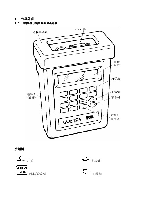
1. 仪器外观1.1 手操器(遥控监测器)外观公用键开 / 关上移键回车/设定键下移键1 QUINTOX—KM9106操作手册 1.2 分析仪外观QUINTOX—KM9106操作手册2 1.3 标准探针3 QUINTOX—KM9106操作手册1.4 分析仪的连接QUINTOX—KM9106操作手册 42.安全警示由于采样烟道气中可能含有易挥发的有毒物质,使用本仪器一定要在通风良好的地方,操作人员必须经过严格的操作培训。
3. 首次使用充电12小时检查是否有仪器所需要的所有部分仔细阅读本手册当你首次使用这台仪器时,你必须先选择设定:显示对比度背光语言选择烟气测量标准温度标准压力标准氧气参考值日期和时间打印输出抬头和电话号码4 .正常开机过程4.1 每次使用前的准备工作开机前检查:氧气传感器是否连接粉尘过滤器是否清洁燃料为重油或煤时二氧化硫过滤器是否安装水收集器及探针中是否存有冷凝水所有连接是否正确打印纸是否安装5 QUINTOX—KM9106操作手册探针及烟气导管中是否充满清洁空气水收集器垂直悬挂连接测量烟道温度插头仪器是否置放于干净,平坦的水平面按开机4.2 自动校准在自动校准期间,仪器的气泵将清洁空气送入所有传感器,使所有的有害气体传感器调整为零,氧气传感器为20.9%。
开机后仪器将首先简要显示抬头信息:接着仪器将显示:使用或将光标移动至 2..Quintox Control.**SELECT FUNCTION**1 . . LOGGER CONTROLQUINTOX—KM9106操作手册 6按键确认后,仪器将显示:时间将从300倒计至零。
如果仪器刚刚使用过则无须300秒即可完成自动校准,否则将一直倒计至零。
每次自动校准结束时仪器会发出提示音并显示出当前燃料种类。
按仪器将自设定有害气体传感器调整为零,氧气传感器为20.9%。
下屏显示的是仪器的‗主显示页面‘:注意:建议每使用2小时后对氧气传感器进行一次重新校准以保证仪器的最大精度。
GATOR ®EK6IDL Battery-powered Dieless Crimping T ool52066203© 2014 Greenlee Textron Inc.2/14Serial NumberRegister this product at EK6IDL Battery-powered Dieless Crimping ToolGreenlee / A Textron Company4455 Boeing Dr. • Rockford, IL 61109-2988 USA • 815-397-70702DescriptionThe EK6IDL Battery-powered, High-speed Dieless Crimping Tool is a hand-held, self-contained crimping tool i ntended to crimp copper cable.This tool is protected by U.S. Patent No. 6,276,186, 6,401,515, 6,718,870, 7,086,979, 7,216,523, and 7,254,982.SafetySafety is essential in the use and maintenance of Greenlee tools and equipment. This manual and any markings on the tool provide information for avoiding hazards and unsafe practices related to the use of this tool. Observe all of the safety information p rovided.Purpose of this ManualThis manual is intended to familiarize all personnel with the safe operation and maintenance procedures for the following Greenlee tool: EK6IDL Battery-powered Dieless Crimping Tool Keep this manual available to all personnel.Replacement manuals are available upon request at no charge at .Do not discard this product or throw away!For recycling information, go to .All specifications are nominal and may change as design improve-ments occur. Greenlee Textron Inc. shall not be liable for damages resulting from misapplication or misuse of its products.GATOR is a registered trademark of Textron Innovations Inc.Blackburn is a registered trademark of Thomas & Betts.KEEP THIS MANUALTable of ContentsDescription .....................................................................2Safety .............................................................................2Purpose of this Manual ..................................................2Important Safety Information .....................................3–4Identification ...................................................................5Specifications .................................................................5Operation ....................................................................6–7cUL and UL Classified Crimps .......................................8 Connector Table ..........................................................8Maintenance ...................................................................9Troubleshooting (10)EK6IDL Battery-powered Dieless Crimping ToolGreenlee / A Textron Company4455 Boeing Dr. • Rockford, IL 61109-2988 USA • 815-397-70703IMPORTANT SAFETY INFORMATIONEK6IDL Battery-powered Dieless Crimping ToolGreenlee / A Textron Company4455 Boeing Dr. • Rockford, IL 61109-2988 USA • 815-397-70704Note: Keep all decals clean and legible, and replace when necessary.IMPORTANT SAFETY INFORMATIONEK6IDL Battery-powered Dieless Crimping ToolGreenlee / A Textron Company4455 Boeing Dr. • Rockford, IL 61109-2988 USA • 815-397-70705IdentificationSpecificationsCrimping ToolLength........................................................................................................15.75" (400 mm)Width ..........................................................................................................2.87" (72.9 mm)Depth ...........................................................................................................4.50" (114 mm)Weight ................................................................................................................6.6 lb (3 kg)Crimping Force ...............................................................................................6 tons (53 kN)Hydraulic Oil .........................................................52057878 biodegradable hydraulic fluid Recommended Operating Temperature Range ...................5 °F to 122 °F (–15 °C to 50°C) Crimping Capacities Maximum Cable SizeCopper .........................................................................................................600 kcmil Aluminum .....................................................................................................350 kcmilBattery Charger ........................................................................Read the instructions suppliedwith the battery charger1. I ndenter2. Head3. Latch4. Retract Button5. LED Indicator (red)6. Battery Lock7. Battery Cartridge8. LED Work Light (white)9. Trigger54792168352047087120 VAC corded adapter 52047088230 VAC corded adapter 5204919018 V , 1.5 Ah lithium-ion battery 5204918918 V , 3.0 Ah lithium-ion battery52054992Li (18 V) to NiCd, NiMH (12 V) charger adapter 52049201120 VAC, 18 V charger 52049202230 VAC, 18 V charger 5204920412 VDC, 18 V chargerEK6IDL Battery-powered Dieless Crimping ToolGreenlee / A Textron Company4455 Boeing Dr. • Rockford, IL 61109-2988 USA • 815-397-70706OperationCharging the BatteryRead the instructions supplied with the battery charger.LED Work Light (white)This LED automatically turns on when the trigger is pulled. It remains on for 10 seconds after the trigger is released.LED Indicator (red)This tool is equipped with a special circuit board incor-porating several important features to inform the user about the current status of the unit. The LED signals in the following cases:Pressure SensorThis tool is equipped with a pressure sensor that alerts the user of an incomplete crimp.• If the tool is manually retracted before completion of a crimp, the red LED and an audible beep will be active for 2 seconds.• If the tool is unable to reach the required crimp force, the red LED, work light, and an audible beep will pulse until after the trigger is released.EK6IDL Battery-powered Dieless Crimping ToolGreenlee / A Textron Company4455 Boeing Dr. • Rockford, IL 61109-2988 USA • 815-397-70707Preparation1. Select a proper size and type of connector tocorrespond with the wire or cable.2. Strip the cable to an appropriate length. Follow theconnector manufacturer’s instructions.Note: Apply an oxide inhibitor, if required.Refer to the connector manufacturer’s instructions.Crimping1. Insert the cable fully into the connector.2. Place the connector into the V of the crimping head,as shown below.Connector3. If open, close the crimping head. Make sure thehead and latch are fully engaged.4. For a cUL or UL classified crimp, complete thenumber of crimps specified in the “Connector Table” in this manual.5. For a single crimp, position the connector so thecrimp will be located at the center of the barrel.6. Depress the trigger to advance the indenter. Holdthe trigger down until the indenter automatically begins to retract.Note: If the crimping tool does not automatically retract, the crimp is incomplete.It is normal for the battery load display to light at both the beginning and near the end of the crimping cycle.7. Release the trigger until the indenter retractscompletely.8. To stop the ram from returning fully, activate thetrigger for a brief moment. This activation will close the retraction valve and stop the retraction motion.9. Lift the latch to open the crimping head and removethe connector.Note: If it is necessary to retract the indenter before a crimp cycle is complete, push the retract button. Pushing the retract button will result in completeretraction of the indenter.Operation (cont’d)EK6IDL Battery-powered Dieless Crimping ToolGreenlee / A Textron Company4455 Boeing Dr. • Rockford, IL 61109-2988 USA • 815-397-70708cUL and UL Classified CrimpsCrimps made with the Greenlee EK6IDL Dieless Crimping Tool are cUL and UL classified on standard concentric, compressed, or compact stranded copper cable with the connectors listed here.Refer to the “Connector Table” for the brand names and model numbers of appropriate connectors and the number of crimps required.Connector Table(NOT for use with flex, navy or welding wire)Copper Connector Type**Anderson Blackburn ®Burndy ILSCO Panduit T & B Penn-Union ** Tyco (AMP)Copper SplicesVHSS VHSCSP CUYS-L YSCT CTLSCSS SCS SCL, SCH54506 to 5452854806 to 54828BCU BBCU—Copper LugsVHCS VHCLCTL CTL-L LCNYA, YA-L, YA-2L YA-2LN, YA-2N YA-L-TC, YA-L-2TC YA-2TC, YAZ YAZ-2N, YAZ-2TC CLN, CLW, CSWCRA, CRB, CRCCRA-L, CRB-LCRA-2LCRB-2LCRC-2LLCASLCALCBLCD, LCCLCAN54106 to 5412854206 to 5422854906BE to 54928BE 54854BE to 54882BEBLU BBLU1099898-2 to 1-1099898-51099899-2 to 1-1099899-91099939-1 to 1-1099939-5* Number of Crimps Copper Cable Size:8 AWG–600 kcmil11111111* When crimping with the EK6IDL crimping tool, use the number of crimps listed in this tableinstead of the number provided with the connector. ** 6 AWG to 600 kcmilEK6IDL Battery-powered Dieless Crimping ToolGreenlee / A Textron Company4455 Boeing Dr. • Rockford, IL 61109-2988 USA • 815-397-70709MaintenanceDailyBefore use:1. Inspect the tool for wear or damage, such as cracks,gouges, or chips.2. Inspect the tool for damage or leaks.3. Inspect the rotation of the head assembly. Fullyretract the ram. The head should rotate no more than 360°. If damage is detected, send the tool to a Greenlee A uthorized Service Center for inspection.After use:1. Use a damp cloth and mild detergent to clean thehousing. Allow the housing to dry.2. Fully retract the ram. Place the tool in the carryingcase and store in a cool, dry place.3. If necessary, recharge the batteries. Refer to theinstructions supplied with the battery charger.Monthly1. Thoroughly clean all surfaces.2. Check the oil level.Annually or After 10,000 Crimps 1. Replace the hydraulic oil.2. Send the tool to a Greenlee A uthorized ServiceCenter for inspection.Checking the Oil Level1. Remove the screws holding the housing covertogether.2. Point the crimping head downward and remove theoil reservoir plug. Fill reservoir if necessary.3. Replace the oil plug and housing cover.Warranty ClaimsSend tool to Greenlee CTSC Service Center.EK6IDL Battery-powered Dieless Crimping ToolGreenlee / A Textron Company4455 Boeing Dr. • Rockford, IL 61109-2988 USA • 815-397-707010ProblemPossible Cause Probable Remedy Tool is inoperative.Dirt, contaminants, etc., in ram area of tool.Clean tool.Tool battery contacts damaged.Reform contacts.Tool components worn or damaged.Return tool to a Greenlee A uthorized Service Center.Motor is inoperative.Low or uncharged battery.Try known charged battery. Inoperative battery may be discharged or may have reached life expectancy.Broken switch components.Return tool to a Greenlee A uthorized Service Center.Motor runs but tool will not complete a cycle.Oil level low.Return tool to a Greenlee A uthorized Service Center.Air in hydraulic system.Pull trigger and hold retract button simultane-ously. Run for approximately 10 seconds, and then attempt to crimp. If unsuccessful, return tool to a Greenlee A uthorized Service Center.Cold oil.Pull trigger and hold retract button simultane-ously to warm oil. Store tool in warm area.LED glows for 20 seconds.Battery charge low.Charge or replace battery.Tool loses oil.Damaged internal seal.Return tool to a Greenlee A uthorized Service Center.Note: For warranty claims, send tool to Greenlee CTSC Service Center.TroubleshootingBefore You Begin1. Make sure that the battery is charged. Recheckthe battery after several minutes to make sure the battery is holding its charge. 2. Use a nonflammable contact cleaner or pencileraser to clean the electrical contacts on the battery and tool.3. Reinstall the battery and check the tool again.EK6IDL Battery-powered Dieless Crimping Tool11Greenlee / A Textron Company4455 Boeing Dr. • Rockford, IL 61109-2988 USA • 815-397-70704455 Boeing Drive • Rockford, IL 61109-2988 • USA • 815-397-7070 An ISO 9001 Company • Greenlee Textron Inc. is a subsidiary of Textron A Tel: 800-435-0786Fax: 800-451-2632Canada Tel: 800-435-0786Fax: 800-524-2853International Tel: +1-815-397-7070Fax: +1-815-397-9247。
产品说明xyJKFG智能无功补偿控制器使用说明书成都星宇节能技术股份有限公司非常感谢您选择了我们的产品! 使用之前请仔细阅读并妥善保管本说明书目录一简述 1二技术指标 1三型号说明 2四面板功能及显示说明 2五操作说明 3六接线说明7七调试说明9八安装说明9九产品目录10注意事项10一简述xyJK系列智能无功补偿控制器是将人工智能成功运用于低压配电设备控制系统中,由于是无功型的控制器,其控制功能的完备,使补偿效果达到了最佳的状态。
当控制物理量为无功功率(Q)时能兼顾功率因数,较完善的解决了功率因数型控制器的缺陷,在运行中既能保证线路系统稳定、无振荡现象出现,又能兼顾补偿效果,将补偿装置的效果发挥得淋漓尽致;当线路在重负荷时,如果cosφ已达到0.99(滞后),只要再投一组电容器不发生过补,也还会再投入一组电容器。
当线路无电流互感器时,控制物理量转为电压(U),此时能根据当地的电压高低自动调节电压。
二技术指标2.1 产品引用标准GB/T15576-1995 低压无功功率静态补偿装置总技术条件DL/T597-1996 低压无功补偿控制器订货技术条件JB/T9663-1999 低压无功功率自动补偿控制器2.2 环境条件Ø 环境温度:工作时-25℃~70℃;极限、运输、储存时-40℃~80℃Ø 相对湿度:40℃时20%~90%;50℃时90%Ø 大气压力:79.5 kPa~106.0kPa(海拔2500m及以下)2.3 电源工作电压:220V±20%;频率50Hz±5%;正弦波形总畸变率≤5%2.4 电压输入模拟量: 380V(三相均衡补偿)2.5 测量精度Ø 电压模拟量(80%~120%额定值): 0.5级Ø 电流模拟量(20%~100%额定值):0.5级Ø 相位角ф在-30°~+60°时,功率:2级;功率因数:1.5级2.6 补偿方式及投切方式Ø 补偿方式:共补型(三相均衡补偿)Ø 投切方式:循环投切2.7 浏览实时运行参数Ø 共补型:电压Uac (V);电流Ib (A);功率P (10kW);Q (kvar);功率因数PF2.8 控制对象及控制门限设定范围Ø 控制对象为无功功率时,控制门限设定范围:投入门限 1 ~ 999kvar切除门限:1 ~ 999kvarØ 控制对象为电压时,控制门限设定范围:共补型:电压投入320 V ~400V、切除门限380 V ~456VØ 过压保护值共补型:380 V~460V;Ø 欠压保护值共补型:240 V~380V;Ø 动作延时时间1 s~150sØ 电流变比1(5:5) ~999(4995:5)Ø 电容容量:0~99kvar;当容量为0时,表示此路未接电容Ø 动作误差:<±20%;动作回差:6 V~12VØ 控制器灵敏度:K≤0.1AØ 过电压保护分断总时限不大于60s;切投动作时间间隔不小于120s2.9 输出触点容量12V或~220V。
Franz Janschitz GesmbH Cream separator Milky FJ 90 PPMilky FJ 130User’s manualTABLE OF CONTENTSGeneral safety recommendations 2 Technical Specifications 3 Unpacking and Set Up 3 Accessories 3 Assembling Procedure 4 List of composing parts 5 Top Bowl assembling Procedure 6 Skimming Procedure 7 Skimming Regulation 8 Maintenance and Cleaning 9 Top Bowl cleaning Procedure 10 Spare parts ordering Procedure 11 Warranty 11GENERAL SAFETY RECOMMENDATIONS•Before any installation read this manual very carefully.•Make sure, that you have closed top bowl fixing nut tightly enough.•Disconnect device from mains before cleaning.•Don`t repair the device by yourself, in case of malfunction rather call authorized service provided by your distributor.•Take care that water or humidity will not come into the device, specially by cleaning procedures.•In case of serious malfunctions unplug the device from mains and call authorized service.•In case that device is not functioning properly even you have exactly followed instructions described in this manual, you are allowed to use only those procedures which are allowed by manual. Use of any other procedures or adjustments could result in device destruction or longer service time. Injuries connected with such procedures can not be matter of any product liability claims.We are glad that you decide to buy our cream separator and we promise you that it willTECHNICAL SPECIFICATIONSRecommended skimming capacity is volume of the milk that can be skimmed within one skimming cycle. It depends how much solid parts are in the milk. If the flow of the skimmed milk is reduced than the discs and the bowl must be cleaned.UNPACKING AND SET UPTake the device out of the cardboard box and remove packing inserts. Place it on the plain and stable surface in clear and dry place. Fixing the device on the surface is recommended. If you want to fix it on the surface, take the screws and fix it on the surface.ACCESSORIESIn each package you will find also following accessories: •Operating Manual•Cleaning brush 371067 •Key for bowl fixing nut and cream screw 3712069 •Spare rubber washer 3711033•Screws90 l130 l Operating V oltage (model 230V)V / Hz 230 / 50230 / 50Operating V oltage (model 115V)V / Hz 115 / 60115 / 60Motor Power W 7070Max. Rotating speed RPM 95009500Max. Capacity l / h 90130Max. Container capacityl 1210Recommended capacity for skimming l to 60to 100Relief disc pcs 711Plain disc pcs 610Net weight kg3,504,70Protection typeIP 23IP 23Please note!Be careful not to use cream separator with damaged mains cord!ASSEMBLING PROCEDURE1.Put the housing on a desk or other plain and stable surface.2.Put assembled top bowl on the conical motor beam and softly press it.3.Put skimmed milk funnel on the top of the housing and then also cream funnel on the topof previous one.4.Turn top bowl with hand and check if is not touching one the funnels and adjust funnels todesired position for skimming.5.Place the holder for milk container on the top of both funnels. Place floating device in it.Then place milk container on the top. Fix all together with holder on housing ( look picture below).6.Place closing cork in the hole situated in the middle of milk container. The narrow side ofthe closing cork handle must be turned away from the cut in the container ( see picture).The milk outflow will be closed.Fixing parts with rubber holder (detail). Only on FJ 130TOP BOWL ASSEMBLING PROCEDURE1.Put the rubber washer in to the notch of top bowl bottom part.2.Place the metal discs. You have to take care by discs placement - device uses two different types of disks - plain discs and relief discs. First you have to insert relief disc, then plain disc and repeat the procedure until all discs are placed. By disc placement avoid any use of force. With gently shaking and turning of the top bowl bottom part all the discs will find their place very easily.3.Put plastic partition in the top bowl cover part.4.When assembling place both assembled parts of top bowl together. Take care that top bowl cover part mark ˝0˝ and top bowl bottom part ˝0˝ are in the same direction.5.Screw the top bowl fixing nut with hand and fix it strongly with the fixing key. The mark ˝0˝ must stay in the same direction. The fixing nut must be strongly fixed, because it is Please note!The closing cork must be closed, when you fill the container. This means that the thick side of the closing cork handle must be turned to opposite direction of the cut in the container.3 - Relief disc4 - Plain discSKIMMING PROCEDUREBest skimming results are achieved if you start to skim immediately after milking. If milk is cooled, you have to warm it up to temperature between 30 to 35 ºC. You can not skim milk with temperature lower than 30 ºC. When the milk is properly warmed up, pour it in the container.•Switch on cream separator with switcher 0 / I and wait 30 seconds that top bowl reaches working speed.Cream separator FJ 130 has above the switcher a signal lamp which, by switching on the separator, shines red, and when machine reaches working speed starts to shine green.•Only then you are allowed to turn closing cork to open position. The end of the closing cork is turned to the cut (tooth) in the container and flow is opened.•If milk is coming out of the housing hole means, that:o You have opened closing cork before the motor had reached working speed,o Top bowl nut was not fixed enough,o Rubber washer is placed badly or it is destroyed.When this is the case, close the closing cork, turn the milk separator OFF and correct the problem.Please note!After you have finished skimming procedure pour approximately 1/2 l of skimmed milk back into milk container. This will clean the rest of cream in the top bowl. After all procedures taken, simply turn OFF the device and wait until motor stops.Closing cork must always be closed before you turn off the device !Before each skimming procedure, the bowl must be clean and dryPlease note!Always check if rubber washer is damaged or too much extended. In such case you have to replace it with new one.SKIMMING REGULATIONThe cream separator is factory adjusted, so you get around 10 % of cream from whole milk volume at milk temperature 35 ºC. If you want different density or volume of cream, you can adjust hexagonal adjusting screw (placed in the plastic partition in top bowl upper part).•If you want more density cream – smaller volume, you have to turn it towards right (clockwise)•If you want less density cream – higher volume, you have to turn it towards left (counter clockwise). In most cases it is enough to turn adjusting screw for ¼ of the rotation.Cream adjusting screw details and function- Smaller cream volume and higher cream density+ Higher cream volume and smaller cream densityPlease note!You have to take care that not fix the adjusting screw too deep, because you can harm the screw coil! You have to take care not to unscrew the regulation screw too much. If you have done so, you will have problems by disassembling the plastic partition and the top bowl upper part.MAINTENANCE AND CLEANING1.All parts of the top bowl should be cleaned with hot water in which you should add somedetergent.2.Rests of milk, cream or other impairs should be cleaned with soft duster or cleaningbrush. Specially take care, that you clean very precisely all the holes in top bowl upper part, top bowl bottom part and in adjusting screw. For cleaning this parts cleaning brush is strongly recommended! Other parts of the separator that come in touch with milk, shouldalso be cleaned with hot water in which some detergent is added. Then rinse parts in clean water.3.If milk or cream rests get dry do not remove them with sharp objects or sharp duster. Itcan easily happen that you ruin galvanic protection cover or plastic parts.4.Before cleaning cream separator housing you must before such procedure alwaysdisconnect device from mains. Clean it first with wet duster and then try it with dry duster. Take care that water doesn´t come into the device.Ensure that no water comes into contact with the motor and other electric part.Please note!Device is protected against direct water access, but you should always take care to avoid that water comes into the device!Before cleaning device must always be disconnected from main supply!TOP BOWL CLEANING PROCEDUREWith the key, which is packed with the cream separator, unscrew top bowl fixing nut as it is shown on the picture.The easiest way to perform this procedure is:1.Fix key into the holes, which are on the top bowl fixing nut2.With stronger press on the other key end turn fixing nut until you release it. After that you can unscrew the nut easily with hand.3.Dismount the top bowl cover with help of fixing nut key and separate all different pieces you will find under the cover - plastic partition, metal discs and rubber washer and clear them with hot water. To achieve better results, cleaning detergent can be added to the hot water.4.Wash all the parts with hot water and dry them with dry and soft duster.LIST OF COMPOSING PARTSPlease note!If you can not mount top bowl off the motor after skimming, shake it gently. Please avoid to use force – you can harm the device most precise parts.Part name FJ 90 EAP FJ 130 -LLEAR-LED 1Foot37110193711019 2Bottom cover31710173171017 3Motor 230 V17595260003Motor 115 V17596260014Main switch3711513711515Cover of main switch3711533711536Housing - green3712005-G375005-G 6Housing - blue3712005-B375005-B 6Housing - silver3712005-S375005-S 7Mains cord assembly 230 V26002260027Mains cord assembly 115 V26003260038Holder assembly/3750699Bearing cover37110133711013 10Top bowl assembly3712021375021 11Outlet for milk3711037375037 12Outlet for cream 3711039375045 13Container holder inox/35051 13Container holder - green3711041-G/13Container holder - blue3711041-B/13Container holder - silver3711041-S/14Floater inox/375059 14Floater plastic3752045/15Container371051375063 16Container washer/371055 17Closing cork37110613711061TOP BOWL PARTSPart name FJ 90FJ 130-LLEAR-LED1Top bowl assembly37120213750212Rubber washer371103337110333Metal disc 1371102537110254Metal disc 2371102637110265Plastic partition371102937110296Cream regulation screw1034441034447Fixing key assembly371206937120698Cleaning brush371067371067Look drawings on page 12!SPARE PARTS ORDERING PROCEDUREFast and reliable shipment of spare parts is possible only if their description is clear enough. At the time of ordering please state clearly:1.Type of cream separator.2.Serial number printed on label plate at the rare side of device.3.Part name and code number of wished spare part.WARRANTY1.In case of troubles consult with your salesman or call authorized service organizedestablished distributor.2.Equipment is warranted to be free from defects in material and workmanship for a periodof 12 months against faulty components and assembly. Our obligation under this warranty is limited to the repair or replacement of the instrument or part thereof, which shall within12 months after date of shipment prove to be defective after our examination.3.Defects or injuries of the device, which are result or improper assembly, use, connect ormaintenance are not covered by this warranty.4.The warranty also doesn´t cover:•Motor, destroyed by water or milk inflow,•Mains cord.5.The given technical specifications are valid only when all conditions in this user`smanuals are fulfilled.6.Other rights, that are not mentioned in upper obligations of the manufacturer, especiallyresponsibility for personal injury, are excluded.Dear Customer!We are sure, that you will find out our cream separator as a helpful tool and we believe that it will serve you for a long time without any problems! We hope it will be recommended also your friends!Thank you for buying it!COMPOSING PARTS DRAWINGS for cream separator FJ 90 and FJ 130Part number 8 and 16 are only on Cream separator FJ 130!COMPOSING PARTS FOR TOP BOWL ASSEMBLY-exploded viewfor cream separator FJ 90 and FJ 130。
QLY9096轮胎式风电吊机使用说明书目录一总体说明二技术参数和部件说明三液压系统使用说明四安全保护装置及调试要求五起重机的荷载试验六起重机使用与维护七转场一总体说明本起重机是吊装风力发电设备的自升、自行式全液压无级调速起重机,工作环境包括西北、东北、海南等偏远荒漠交通不便的地区,使用地区最低温度-40°,使用温度-20~+40°,长途由平板车运输,短途由起重机轮式行走系统完成。
每次转场的安拆由提升、斜拉、变幅、辅助机构等完成。
液压系统采用PLC(可编程序控制器)控制,系统运行操作指令及报警监视信号进入PLC输入端,由PLC对指令进行采样,根据事先编入PLC内存的用户程序产生相应输出来控制液压系统中的电磁阀动作,从而实现了上车各执行部件的相应动作,所以只要通过操作控制台面板上的比例式操作手柄和电控按钮等就能实现液压绞车、液压回转所需的各种动作及动作的速度快慢。
为保证液压系统运行的可靠,液压系统设有吸油过滤、高精度高压过滤及高精度回油过滤和风冷冷却器。
液压系统的各部件或外购件均选用国内外名牌厂家,其中起升绞车、变幅绞车采用的是SAUER-DANFOSS 公司生产的90系列电比例控制闭式泵,其他绞车、油缸采用的是SAUER-DANFOSS公司生产的FR系列负载敏感泵,控制阀采用的是HAWE电比例负载敏感阀,安装在液压绞车集成块上的螺纹插装阀为美国SUN公司产品,辅助控制系统采用的是力士乐系列板式阀,性能优良可靠,便于安装和维护;液压辅件如过滤器等采用浙江黎明液压机电厂产品。
二技术参数和部件说明2.1 技术参数及起重特性曲线表1 QLYK型90t轮胎起重机主要技术参数QLYK 型90t 轮胎起重机起重特性曲线如下图1所示。
1040302011.6载荷6050(t)45(m)14708090起重特性曲线图1 起重特性曲线表2 工作幅度与相应起重量关系表三液压系统使用说明一、变幅绞车:变幅绞车和下车行走拼用一个180ml/r排量的闭式电比例变量柱塞泵,电比例控制采用手柄式电位控制器,由PLC设定手柄式电位器手柄处于中位时电流为零,正反两个最大摆角位置时泵的输出流量为218L/min。
二、起升绞车:起升绞车和下车行走拼用另一个180ml/r排量的闭式电比例变量柱塞泵,电比例控制采用手柄式电位控制器,带刹控制阀SR5采用脚踏式电位器,同时起升绞车的马达制动器控制阀SD8、带刹控制阀SR5还必须增设带有保险盖的带灯按钮以防止误操作,即只有当打开保险盖使按钮处于工作状态时,SD8、SR5才可以得电,否则SD8、SR5处于断电失效的安全状态中。
由PLC设定手柄式电位器手柄处于中位时电流为零,正反两个最大摆角位置时泵的输出流量为252L/min。
三、液压回转:液压回转和下车转向拼用一个130ml/r排量的带负载敏感柱塞泵,液压回转的方向和速度由负载反馈式电比例多路阀控制,电比例控制采用手柄式电位控制器,手柄式电位控制器缓慢往前推,SR6电流由小到大,控制液压回转顺时针速度由慢到快旋转;手柄式电位控制器缓慢往后拉,SR7电流由小到大,控制液压回转逆时针速度由慢到快旋转,手柄处于中位时是停止状态,由PLC设定手柄式电位器手柄处于中位时电流为零,正反两个最大摆角位置时泵的输出流量为90L/min。
四、辅助绞车:辅助绞车和下车转向拼用一个130ml/r排量的带负载敏感柱塞泵,辅助绞车的提升、下放和速度由负载反馈式电比例多路阀控制,电比例控制采用手柄式电位控制器,由PLC设定手柄式电位器手柄处于中位时电流为零,正反两个最大摆角位置时泵的输出流量为25L/min。
其他电气控制:各自封式吸油过滤器、各回油滤油器、各高压过滤器都设有堵塞报警发讯器,当SL1发讯时闭式电比例变量柱塞的补油泵吸油过滤器滤芯堵塞,须更换该滤芯。
当SL2发讯时负载敏感式变量柱塞的吸油过滤器滤芯堵塞,须更换该滤芯。
当SL3发讯时泄油及循环冷却油路回油过滤器滤芯堵塞,须更换该滤芯。
当SL4发讯时系统主回油过滤器滤芯堵塞,须更换该滤芯。
当SL5发讯时,负载敏感式变量柱塞的压力油过滤器滤芯堵塞,须更换该滤芯。
电气操纵控制分为驾驶室控制和现场控制,变幅绞车、起升绞车和液压回转操纵控制要求设置在驾驶室,其他执行机构操纵控制要求设置现场便携式操纵箱。
四安全保护装置及调试要求1.臂架顶部设有风速仪。
可在司机室内读知风速数值,当瞬时风速大于16m/s时,自动报警,当风速仪指示瞬时风速达到20m/s时,司机应及时停机以保证安全。
2.臂架头部设有起重量发送装置,司机室内装有可读知起重量及相应的工作幅度的力矩限制器。
3.变幅机构上设有行程限位装置,用于限制最大和最小幅度。
空载试验时变幅机构从R=45米到R=11.6米全程增幅、减幅的过程中调整极限幅度限位开关动作。
4.高度限位装置吊钩起升超过起升最高高度96m后,触及限位重锤,打开行程开关,发出信号,切断吊钩起升方向的操作,从而确保安全。
此外,在臂架与人字架之间设有防后倾支撑架,其上装有弹簧缓冲器。
起重臂在最小幅度位置调整安装防后倾支撑架。
五起重机的荷载试验荷载试验工作按顺序分为空载、静载和动载三个步骤进行。
5.1试验前的调试和检查5.1.1检查装配是否符合设计要求。
5.1.2检查金属结构有无变形其连接处是否松动,钢丝绳的缠绕是否正确及紧固情况。
5.1.3检查机械部分的安装质量:有预紧力要求的连接螺栓要复拧。
5.1.4检查电气部分的安装质量:电气设备应正常工作,其中必须特别注意、限位开关、安全开关和紧急开关工作的可靠性。
5.2 空载试验5.2.1只有在试验前的调试和检查都符合要求时才能进行空载荷试验。
5.2.2空载试验的试验项目如下:(1)变幅机构:由最小幅度到最大幅度起落起重臂二次,最后起重臂处于最小幅度位置。
(2)起升机构:空钩分别按上升、下降各一次。
(3)回转机构:起重臂在最小幅度时,正反方向各回转一周;起重臂在最大幅度时,正反方向各回转一周。
5.3静载试验5.3.1静载试验的目的是检验起重机及其各部分的结构承载能力。
5.3.2只有空载试验情况正常之后,才允许进行静载试验。
5.3.3静载试验之前,应将起重臂放在最大幅度位置。
5.3.4静载试验的试验项目如下:表5.1 静载试验内容5.4动载试验5.4.1经过静载试验,并经检查合格后,进行动载试验,以检验各部分运转情况及起重机动态稳定性。
试验内容见下表。
表5.2 动载试验内容六起重机使用与维护6.1 安全规则6.1.1 严禁拆除自动控制机构及监测、指示、仪表和报警等装置。
不得随意解除安全报警功能。
6.1.2 不得在工作状态进行维护、调整。
6.1.3 大修、拆装后,必须进行测试和试运转。
6.1.4 当发现不正常噪音和裂纹,应及时停车维修。
6.1.5 严禁超载、带病运行。
6.1.6 驾驶应由经过培训并通过考试的人员负责,再配以辅助人员。
严禁无关人员进入作业区和驾驶室。
操作时,思想要集中,严禁酒后驾驶。
6.1.7 在走合期,起动时严禁猛加油门,严禁猛踩脚踏板变速。
应经常检查各部件运转情况,如转速、压力和温升等变化,有不正常现象应及时消除。
6.1.8 冬季使用时,应进行换季性保养和检查技术状况。
选用合适的液压油、润滑油、燃油和加防冻液,长期停车不用时,要放尽各部积水。
6.1.9 当按下启动钮(启动柴油机),控制启动的继电器触点因发生烧蚀粘合而不能分离时,迅速按下启动机急停按钮,即可切断启动机控制电源并自锁。
排除故障后,需逆时针旋转急停按钮,(急停按钮)会自动弹出而复位。
6.1.10 驾驶员必需带安全帽。
6.2起重机操作前的准备对起重机下车进行全面仔细的检查、整理及清扫,拧紧固件,防止风电吊机在运转时紧固件松动或杂物坠落,保证各运动部件之间无阻碍运转。
检查各润滑点,减速机、油泵等处是否有足够的润滑油(脂)。
全面检查风电吊机电气线路,防止漏接、假接、错接,保证线路通畅。
准备好有关的测试记录表格、测试仪器、仪表和工具。
试车场地必须清理,不得堆放妨碍试车的物体,并在周围做上安全境界的标记。
轮胎起重机的轮胎工作充气压力应符合轮胎起重机规定的气压,其允许差为±3%,起重机作业时所有轮胎应摆正。
起重机打支腿作业时,所有轮胎应离地。
地面应水平、坚实,承压能力不小于3.5Mpa,整机应水平,作业过程中支撑地面不得下陷。
起重机的维护保养各机构的刹车应及时进行检查和调整,如需更换刹车片请及时更换。
要注意检查各部分钢丝绳有无断丝和断股现象,如超过有关规定,必须立即更换新钢丝绳。
经常检查各机构运转是否正常,有无噪音,如发现故障,必须及时排除。
经常检查各部分的连接情况,如有松动,应予拧紧。
所有连接销都必须装有挡圈或开口销。
使用液压油的部件,应严格按润滑中规定进行加油或更换,并按时清洗油箱内部。
经常检查各部位管道接头是否紧固严密,不准有漏油现象。
总装和大修后,初次起动油泵时,应先检查入口、出口是否接反或漏接,转动方向是否正确。
冬季开机需空机运行10-20分钟左右,待油温上升和控制阀动作灵活后再正式使用。
经常检查所有的电线、电缆有无损伤,要及时地包扎和更换已损伤的部分。
检查接线是否良好,不得有松动。
遇到发动机有过热现象,要及时停车,排除故障后再继续进行,发动机轴承润滑要良好,注意轴承磨损情况。
定期检查各安全装置的触点开闭是否可靠,如有不良现象,应立即修复。
七转场7.1转场前的检查首先应检查确认的项目有:变幅拉索应固定好,勿使其在地面上拖动;检查车辆外形的完好性,检查有油、水是否充足,油管、水管各接头是否有渗漏;检查轮胎气压是否符合要求,轮胎是否损坏;各种仪表、灯光、信号等工作是否正常;转向系统、制动系统各部件是否灵活、安全、可靠等。
7.2柴油机启动全车操作按常规汽车操作习惯设计,驾驶座正前方为方向盘和操作面板,右侧为微电操作面板。
下面右侧有二个脚踏板,油门踏板和制动踏板。
7.2.1启动发动机首先将电源急停开关顺时针旋起,然后将钥匙开关旋到“1”位,此时则可以启动发动机。
正常启动:当空气温度高于“0”度时,可直接启动。
适当增加一些油门后将启动开关压下,顺时针旋转到底、此时应可使发动机启动起来,如发动机不能起动,再次启动,当听到发动机正常的声音后,发动机已启动起来,松开启动开关,观察各仪表情况,并将油门先调节到怠速状态,当气压达到0.7Mpa以上时,方可开车。
冷启动:当空气温度低于“0”度时,将预热开关压下,等待26秒后,此时预热指示灯已亮,再将启动开关旋转到底,则可按发动的正常启动步骤启动。
发动机每次启动的时间不得超过6秒,连续启动的次数不得超过3次,当超过3次时,应等待3 - 5分钟,使电瓶电压恢复后再重新启动发动机。
7.3 柴油机停车7.3.1柴油机严禁从满负荷突然停车,而应松开脚油门踏板后经短时间空转使温度平衡后再停车。