Ver5.0调试软件功能简介及使用说明书
- 格式:pdf
- 大小:2.10 MB
- 文档页数:21
热回收转轮操作和维护手册DTR-VS-ver.5.0 (09.2017)IEC/EN 60439-1 +AC Low voltage switchgears and controllersVTS 保留非预先通知而修改的权利目录1. 介绍 (2)2. 技术数据 (3)2.1. 驱动单元基本参数 (3)2.1.1. 结构 (3)2.1.2. 驱动器操作 (3)2.2. 技术规范 (4)2.2.1. 结构 (4)2.2.2. 操作参数 (4)2.2.3. 元器件的额定参数 (4)2.3. 驱动单元的安装和配置 (5)2.4. 含变频器和VTS自控的驱动单元安装和配置 (5)2.4.1. 热回收转轮驱动回路的接线图 (5)2.4.2. 驱动单元的安装和配置 (6)2.4.3. 电机防护 (7)2.5. 自控系统的驱动单元安装和配置 (7)2.5.1. 热回收转轮驱动回路的接线图 (7)2.5.2. 热回收转轮驱动单元的控制 (8)2.5.3. 变频器配置例子 (8)2.5.4. 电机保护 (9)2.6. 系统中带有EC调速器的驱动单元安装和配置 (10)2.6.1. EC调节器的ModBus RTU/RS485参数 (11)2.6.2. 通过MODBUS设置旋转速度 (12)2.7. 安装建议 (13)3. 保存和运输 (14)4. 启动 (14)5. 维护 (15)5.1. 热回收转轮和驱动皮带 (15)5.2. 转轮密封 (16)1. 介绍本文档描述了关于热回收转轮的参数、运输、保管和服务内容。
●在进行任何动作前,务必详细阅读本文档。
2. 技术数据2.1. 驱动单元基本参数2.1.1. 结构本驱动单元是每个热回收转轮的完整部件。
基本构成如下:●变频器/EC电机控制器(取决于不同的版本或区域)●热回收轮芯●轮芯驱动皮带传动装置●电机减速器-马达带有减速齿轮2.1.2. 驱动器操作驱动单元用于启动并平缓地控制热回收转轮,使得速度在3-10rpm范围内。
业务技能“最新5.0软件”升级版安装说明第一篇:业务技能“最新5.0软件”升级版安装说明附件2:业务技能“最新5.0软件”升级版安装说明一、从NOTES上“保存”下载出来“最新5.0软件”压缩包(注:保存到“我的文档”)。
二、下载出来后,点击鼠标右键,解压文件包(注意事项:安装测评系统前,务必将以前安装的测评软件,从“控制面板”内的“添加/删除”程序中删除原安装的所有业务技能软件,再行安装该软件,否则软件冲突不能正常使用;同时在安装软件前务必关闭电脑所有操作程序)。
三、解压后点击打开“业务技能测评(IT蓝图5.0更新版)安装软件”文件包,再点击“setup.exe”安装文件。
四、点击“下一步”、“下一步”……(单位名称随便填写)不改变路径,安装序列号为“2011-004-0303”,“下一步”……“完成”。
安装完成后应重新启动电脑。
五、安装完毕后,插上“加密锁(狗)”即可使用。
不清楚事项请查看软件“帮助”功能或原《中国银行员工业务技能测评系统V5.0版》使用说明书。
第二篇:业务软件V1.15.6版本升级说明TopIcis.R.1.15.6升级内容培训培训内容一:V1.15.6版本升级涉及执法、外资、OA业务模块内容培训: 执法:1.ICIS00017443 CH-TP-091216-027 办案人员对纠错案件不需要重走流程修改,实际操作步骤:案件某一环节的材料需要补录或纠错的,不应该让办案人员重走流程,应该让办案人员直接进入该环节进行补录或纠错。
实施分析:处理方案:一般案件下新增加一般案件信息修改功能,对结案的案件可以进行受理修改案件信息。
2.ICIS00020740 HF-TP-100413-013 执法流程问题实际操作步骤:目前软件中,执法流程走到调查取证时,必须先录入“询问通知书”才能再录入“询问笔录”。
而实际工作中,有可能通过电话等方式直接叫当事人来录询问笔录,因此要求软件去除此步骤限制。
目录系统简介 (1)一.功能简介 (2)11录像功能 (2)12视频显示 (2)13报警功能 (2)14控制功能 (3)15管理功能 (3)16日志 (3)17电子地图 (3)28网络功能 (4)二.使用说明 (4)21系统初级使用说明 (4)22系统高级使用说明 (13)22.5电子地图 (19)三.客户端使用说明 (21)31软件介绍 (21)四.运行操作: (21)41客户端的配置 (22)42客户端日志的管理 (25)五.硬件 (28)51硬件安装 (28)52系统主机外接设备连接图 (29)53联动报警的实现 (29)54解码器列表 (30)结束语 (31)系统简介V5.0系列数字监控系统是当今多媒体、图像处理、计算机等各项最新技术高度结合的产品。
V5.0系列数字监控系统以计算机为中心,图像数字处理为基础,实现图像监视系统的小型化、高清晰度化、自动化和网络化。
给图像监视工程提供了更优的性能、更灵活的系统组建、更好的系统管理,是图像监视系统从模拟到数字的一个质的飞跃。
它利用最新的图像数字处理技术将模拟视、音频信号转化为数字信号,在计算机显示器上实时显示1—36路以上活动图像的同时,在压缩时将各路视、音频信号分别存储于计算机硬盘内,在计算机上实现信号的监视、记录、回放。
它对视、音频信号采用MPEG-4编码,完全动态码流,使相同质量的录像资料保存时占用更小的空间。
本系统软件支持MPEG1、MPEG2、MPEG4、H.264、D1等算法的程序应用,按硬件的配置,可以满足图像录像质量720×576、1024×768分辨率的要求,而且具完全实时效果,并最大限度地实现了网络传输无极限扩展功能,IE浏览与数据传送等强大功能。
所以它可以应用在银行、电力、电信、交通、军队、智能小区、商业场所、公检法机关,医疗教育系统等领域。
一.功能简介11录像功能1.1.1最大视频/音频处理能力监视和记录帧数 25帧/秒/路摄像机输入 1-36路输入,1V峰值电平,75欧姆BNC端口视频信号格式 PAL/NTSC ,彩色、黑白图像压缩 MPEG-4/D1、像数720×576、352×2881.1.2录像激活方式方式一:预约方式,在事先设定好的录像时间内进行录像,录像时间可按照一周的每一天的每一小时进行设置。

CVI ™,FlexMotion ™,LabVIEW ™,and ™are trademarks of National Instruments Corporation.Product and company names mentioned herein are trademarks or trade names of their respective companies.322284C-01©Copyright 1998,2000National Instruments Corp.All rights reserved.July 2000F LEX M OTION 5.0FlexMotion 5.0is the motion control software and VIs for interfacing with all National Instruments FlexMotion series motion controllers.Caution If you have developed motion control systems using a previous version of FlexMotion,you may need to recompile your code before it will work correctly with FlexMotion 5.0.Refer to the Compatibility Issues section of this document for more information.These release notes discuss compatibility issues,describe how to install FlexMotion 5.0and related hardware,and summarize changes andimprovements associated with this version.Topics include:• FlexMotion 5.0 Contents•Changes and Improvements •Controllers •Compatibility Issues •FlexMotion Software Installation •Hardware Installation •Using the Online ManualsFlexMotion 5.0ContentsFlexMotion VI Library 5.0is the motion control software for interfacing with all National Instruments FlexMotion series motion controllers using the National Instruments LabVIEW and LabVIEW DSC visualdevelopment environments.The FlexMotion VI Library 5.0is compatible with LabVIEW version 5.1or later and LabVIEW DSC version 2.0or later.FlexMotion Software 5.0is the motion control software for interfacing with all National Instruments FlexMotion series motion controllers using C,LabWindows/CVI,or Visual Basic development platforms.™Changes and ImprovementsThere are several changes and improvements to the FlexMotion VI Libraryand Software functions that make them easier to use and expand theirfunctionality.Code you have created and validated in the past still workswith FlexMotion5.0.A broad description of changes made in version5.0follows.Measurement&Automation ExplorerMotion control is now integrated into the National Instruments globalconfiguration utility,Measurement&Automation Explorer(MAX).Youcan set static motion parameters in the configuration panels,which reducesyour programming tasks to a simple Initialization call and motion controlapplication development.MAX for motion also includes an interactiveenvironment that allows you to interactively test your motion configurationand view single or multi-axis movement in plot graphs.Reentrant LabVIEW FlexMotion VIsThe FlexMotion VIs are now all reentrant,allowing LabVIEW tosimultaneously execute two instances of the same VI on seperateprocessors in a multi-processor system running Windows2000/NT.Even on a single-processor computer,multiple instances of a VI can betime-sliced more effectively.With the FlexMotion VIs marked as reentrant,they cannot be debugged,and the front panel of an open VI will not reflect the values last sent to it.If you need to debug a FlexMotion VI with your application,you cantemporarily uncheck the Reentrant Execution box in the VI setup options.ContouringContouring allows you to create any arbitrary motion profile.You specifyan array of positions that are a specified interval apart,in milliseconds.Your FlexMotion controller then uses a cubic spline algorithm to smoothlyinterpolate between the contour positions.For more information oncontouring,refer to the FlexMotion VI or function online help. FlexMotion Expanded Example SetSeveral programming examples have been added to the13examples inthe previous release of the FlexMotion VI Library.You can find theseexamples in examples»Motion»FlexMotion»Onboard.llb under theLabVIEW Open VI option.You can find C and Visual Basic examples in C:\\ProgramFiles\National Instruments\Motion\FlexMotion\Examples.Limit FiltersIn FlexMotion5.0,the limit and home inputs must be active for at least1ms to guarantee it will be recognized,instead of the20µs filter in theprevious version of FlexMotion.This digital filter is always enabled andcan not be disabled.Changes to VIs and FunctionsThe VIs and functions in Table1have been added to or changed inFlexMotion5.0.Table1.FlexMotion VI and Function Changes and AdditionsVI Function DescriptionInitialize Controller flex_initialize_controller New VI/function;replaces all previous initialization mechanisms;applies configuration settings from MAX to your controllerConfigure Buffer flex_configure_buffer New VI/function;allows you to set up a buffer on your FlexMotion controllerWrite Buffer flex_write_buffer New VI/function;after a buffer has been configured,this VI/function allows you to write to the buffer.Read Buffer flex_read_buffer New VI/function;after data is written to a buffer, this VI/function reads the dataCheck Buffer flex_check_buffer New VI/function;this VI/function provides information about the state of the buffer and how many points have been written to or read from the buffer.Clear Buffer flex_clear_bufferNew VI/function;clears a buffer from RAMSet Breakpoint Output MOMO flex_set_breakpoint_momoAllows you to specify an input vector;the VI hasa new terminal and the new function replacesflex_set_bp_momo©National Instruments Corporation3FlexMotion Version5.0Set Operation Mode flex_set_op_mode Existing VI/function enhanced with two additional operation modes for contouringConfigureHigh-Speed Capture flex_configure_hs_captureNew VI/function replaces Set High-Speed CapturePolarity and flex_set_hs_cap_pol.You cannow choose six configurations,including digitalinput on7344family FlexMotion controllers.Enable High-Speed Capture flex_enable_hs_captureNew VI/function replaces Enable High-SpeedPosition Capture and flex_enable_hs_caps.Enable Breakpoint Output flex_enable_breakpointNew VI/function replaces Enable Breakpoint andflex_enable_bp,and allows you to enable or disablea breakpoint without having to set the breakpointconfiguration parameters.Configure Breakpoint flex_configure_breakpointNew VI/function;contains the configurationparameters previously located in the EnableBreakpoint VI/function.Select Signal flex_select_signal Existing VI/function has new options for routing encoder and index signals over RTSI,making cross-board synchronization easier.Wait for Move Complete/ Wait for Blend Complete Does not applyto equivalentfunctionsExisting VIs;the default timeouts have changedfrom1,000ms(1s)to10,000ms(10s).Read I/O Port/Set I/O Port Polarity/ Set I/O Port MOMO flex_read_port/flex_set_port_momo/flex_set_port_polExisting VIs/functions;the Real-Time SystemsIntegration(RTSI)port has changed from port5toport9.Your older VIs and programs that use port5will still work with this release,but will cease tofunction with the next release.Table1.FlexMotion VI and Function Changes and Additions(Continued)VI Function DescriptionFlexMotion ControllersThe FlexMotion controllers and their respective bus types are listed inTable2.Table2.FlexMotion Series Motion ControllersController Bus TypePXI-7344PXI/CompactPCIPCI-7344PCIFW-7344*IEEE-1394PCI-FlexMotion-6C PCIPC-FlexMotion-6C ISA*Windows2000/Me/98only.The FlexMotion5.0software is compatible withWindows2000/NT/Me/9x.Compatibility IssuesIf you have previously developed programs using the FlexMotion VILibrary and/or Software4.5,you should read this section.If you are afirst-time user of FlexMotion,skip this section.This section describes thecompatibility of FlexMotion5.0with earlier versions of FlexMotion.For FlexMotion5.0to work,you must have version5.0firmware or lateron your FlexMotion controller.Refer to the MAX online help forinformation on updating your FlexMotion controller firmware.Your VIs developed with FlexMotion4.5will continue to work withFlexMotion5.0,but National Instruments recommends you update themto take advantage of the new features in version5.0.Refer to the Changesto VIs and Functions section of this document for a list of new and changedVIs.Error Code Changes Affecting C,LabWindows/CVI,andVisual Basic UsersAs part of the FlexMotion5.0Software release,the error codes returned bythe functions in the FlexMotion DLL have been changed.This changegives you better integration with other National Instruments products.Thischange moves the error codes to the–70000to–79999and70000to79999range with0remaining the value for no error.As always,you should©National Instruments Corporation5FlexMotion Version5.0use the predefined symbolic names found in the MotnErr.h andMotnErr.bas header files.A list of these symbolic names can befound in the FlexMotion Software Reference Online Help.You must recompile existing applications that directly compare returnvalues from a function call to a specific error code.These comparisons willno longer work correctly and your application will not respond as expected.If you cannot recompile your applications,do not install FlexMotion5.0Software.If your code only uses the constant NIMC_noError to check for thepresence of errors,you do not need to recompile.Converting LabVIEW Applications Using Earlier FlexMotion VIsThe4.5release of the FlexMotion VIs provided a way to convert olderLabVIEW applications to use the improved error handling features of thenew VI set.This method of converting user applications is no longer supported byLabVIEW and the5.0release of the FlexMotion VIs.Y ou have threeoptions if you have applications written with the FlexMotion VIs4.0orolder and want to upgrade to the FlexMotion5.0VIs:•You can install the compatibility libraries that contain all the older VIs.•You can rewrite your applications using the new VIs.•You can first install the FlexMotion4.5VIs and go through theconversion process and then install the FlexMotion5.0VIs.To learn more about the conversion process,refer to the FlexMotion VIs4.5Release Notes.The FlexMotion VI Library works with LabVIEW versions5.1and later.If you have an older version of LabVIEW,contact National Instruments foran upgrade.FlexMotion Software InstallationInstall the FlexMotion software before installing a FlexMotion seriesmotion controller for the first time.If you are upgrading from a previousversion of the FlexMotion software,you do not need to remove yourFlexMotion controller before installing the upgrade.Your existingWindows configuration settings are not affected by the upgrade. FlexMotion Complete the following steps to install your FlexMotion software:1.Insert the NI-Motion5.0CD into your CD-ROM drive.The CD willautomatically show the NI-Motion installation screen.2.Click FlexMotion5.0Installation and then choose the Install option.3.Follow the installer prompts through the rest of the installation.4.Refer to the ReadMe.txt file after the installation is complete forlast-minute information not contained in this document or theFlexMotion online help.The FlexMotion software you selected is installed.FlexMotion ServoTuneThe FlexMotion ServoTune application for tuning servo motors isprovided free of charge on your NI-Motion5.0CD in the\Other\ServoTune\FlexMotion directory.To install theServoTune application,run setup.exe from the Disk1subfolder.If you install the FlexMotion VI Library5.0,you do not need to installServoTune.The tuning VIs are included on the FlexMotion LabVIEWfunction palette.You will need to manually enter the PID parameters you established inServoTune into the PID configuration panel in MAX.To access the PIDconfiguration panel:1.Expand the Devices and Interfaces category in the configuration tree.2.Expand the device and default initialization settings items.3.Select Axis Settings from the configuration tree and select ControlLoop from beneath the configuration view.e the slides and numerical edit boxes to enter you PID parameters.The serial number for the ServoTune application,which you need duringinstallation,is f45m45454.Software UpdatesYou can find FlexMotion5.0updates and patches by visiting/motion and clicking on Drivers & Downloads.©National Instruments Corporation7FlexMotion Version5.0FlexMotion Version Hardware InstallationIf this is the first time that you have installed the FlexMotion software on your computer,then complete the following steps to install your FlexMotion series motion controller.Note Refer to Chapter 2,Configuration and Installation ,of your motion controller hardware user manual if you need additional hardware installation and handling instructions.PCI/PXI/FW InstallationComplete the following steps to install your PCI/PXI/FW motioncontroller:1.Shut down your computer.2.If you are installing a PCI or PXI controller,install the controller in an available slot in your computer.If you are installing the FW-7344,connect the controller to your computer ’s IEEE-1394port.3.Restart your computer.4.Click on the Start button on your Windows 2000/NT/Me/9x taskbar and select Programs »National Instruments »Measurement &Automation to launch MAX.Expand the Devices and Interfacescategory in the configuration tree and select your installed FlexMotion controller.MAX automatically assigns the first available board ID to your controller.5.Press F1or select Help »Help Topics »NI-Motion to view the online help for MAX.The online help contains complete information onverifying your configuration,testing the installed FlexMotioncontroller,and downloading new firmware.Your PCI/PXI/FW motion controller is successfully installed.ISA Installation (PC-FlexMotion-6C Only)For ISA installation instructions,refer to the online help topic Adding Your Motion Controller in MAX.To access MAX online help for Motion,click the Start button on your Windows task bar and select Programs »National Instruments »Measurement &Automation .Next,select Help »Help Topics »NI-Motion »Motion Configuration Help from the MAXmenu.©National Instruments Corporation 9FlexMotion Version 5.0Using the Online ManualsThe FlexMotion documentation is shipped with your software as Adobe Acrobat portable document format (PDF)files.The softwaredocumentation is also installed as a Windows online help file.NoteIf you do not already have Acrobat Reader version 4.0or later installed on your system,you can install it from the FlexMotion Software CD.Run the rs40eng.exe file found in the CD ’s Other\Adobe Acrobat\Win32directory.To view the installed PDF documents,click on the Start button on the Windows taskbar and select Programs »National Instruments »Motion »FlexMotion Software 5.0and then the document that you wish to view.This automatically launches the Acrobat Reader and opens the selected PDF file.Y ou can assemble your own printed manuals,printing either the entire documentation set or just the sections relevant to your application.Click on any entry in the table of contents to jump directly to thecorresponding manual page.You can jump to major sections within each document quickly and easily by clicking on the bookmarks.When you choose the View »Go To Page option or are printing pages,you must use the page numbers in the lower left corner of the Acrobat window,not the number displayed in the bottom center of each manual page or listed in the contents and index.Acrobat assigns consecutive numbers to each page throughout the document and displays the page number.The numbers may not match those shown at the bottom center of each manualpage.。
IOLmaster 简要操作简要操作指南指南(Version 5)
测量顺序测量顺序::在进行其他接触式测量前在进行其他接触式测量前,,请预先完成IOLmaster 测量测量。
患者基本资料(必须输入)
按操作杆按操作杆按钮按钮
患者基本资料(必须输入)
屈光状态、视力(可选)
备注(可选) 患者列表
角膜曲率测量
仔细将中心光点移动到绿色十字线中央。
Adjustment Aid”模式下,红绿建议检测位置及顺序
好结果,可重复双峰,需评估
角膜处,固视点靠近晶体对
[注] Array 1.在眼轴长度测量模式下,需根据患者眼部状态
选择测量模式:
有晶体眼/无晶体眼/人工晶体植入眼/硅油填充眼/ 前房型人工晶体眼/背驼式人工晶体眼
2. 快捷键
<D>。
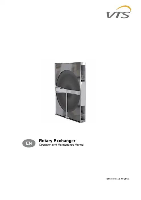
Rotary ExchangerOperation and Maintenance ManualDTR-VS-ver.5.0 (09.2017)IEC/EN 60439-1 +AC Low voltage switchgears and controllersVTS reserves the right to implement changes without prior noticeTable of Contents1. Introduction (2)2. Technical Data (3)2.1. Base Data of the Drive Unit (3)2.1.1. Construction (3)2.1.2. Device Operation (3)2.2. Technical Specification (4)2.2.1. Construction (4)2.2.2. Operation parameters (4)2.2.3. Rated data of the unit components (4)2.3. Installation and Configuration of the Drive Unit (5)2.4. Drive Unit installation and Configuration with Frequency Converter and VTS Automation 52.4.1. Circuit diagram of the exchanger drive circuit (5)2.4.2. Installation and Configuration of the Drive Unit (6)2.4.3. Motor Protection (7)2.5. Drive Unit installation and Configuration in any Automation System (7)2.5.1. Circuit diagram of the exchanger drive circuit (7)2.5.2. Control of the exchanger drive unit (8)2.5.3. Example of a Converter Configuration (8)2.5.4. Motor Protection (9)2.6. Instalation and Configuration of the Drive Unit in System with EC Regulator (10)2.6.1. ModBus RTU/RS485 Parameters for the EC Regulator (11)2.6.2. Rotating Speed Control from MODBUS Level (12)2.7. Recommendations For Installation (13)3. Storage and Transport (14)4. Start-up (14)5. Maintenance (15)5.1. Rotary Heat exchanger and Drive Belt (15)5.2. Rotary seal (16)1. INTRoDUcTIoNThis documentation describes information regarding the data, transport, storage and service of the Rotary Heat Exchangers.●Before taking any action you should absolutely read this document.2. TEChnICAl DATA2.1. Base Data of the Drive Unit2.1.1. constructionThe drive unit is an integral part of each rotary heat exchanger delivered by VTS.Basic elements:●Frequency converter / EC motor controller (depending on version and region)●Exchanger rotor●Rotor drive belt transmission●Motoreducer - engine coupled with reduction gearing2.1.2. Device operationDrive unit is responsible for the start-up and smooth control of rotary exchanger speed in the range of 3 to 10 rpm Array (for TOTAL exchanger up to 20 rpm).Utilizing a wide range of regulator functions, it is also possible to monitor the performance of the drive unit in detail.2.2. Technical Specification2.2.1. constructionInverter-type drive unit with asynchronous motoreducer and belt transmission. Individual elements are located inside the rotary exchanger’s casing in appropriately adapted spaces2.2.2. operation parametersSystem TNU3rated power supply voltage1x(200-230)V ±10% Rated frequency50-60 Hz ±5% Protection class after installing in the VTS AHU IP54Acceptable operating temperature50°CEMC environment12.2.3. Rated data of the unit componentsAHU data engine data inverter dataAHU sizediameter ofexchangerrotortype Pn Un In type UnIn(primaryside)In(secondaryside)fminfmax[mm][kW][V][A][V][A][A][Hz][Hz]21750AC5IK60GU0.063x2300.45SV004iC5-1F LG1x230 5,52,5165530785AC5IK60GU0.060.45175840995AC5IK60GU0.060.4552 551165EC NS65-30-037.230.371x2301.05------751305EC NS65-30-037.230.37 1.051001485EC NS65-30-037.230.37 1.051201680EC NS65-30-037.230.37 1.051501870EC NS65-30-037.230.37 1.051801870EC NS65-30-037.230.37 1.052302240EC NS65-30-037.230.372,13002335EC NS65-30-037.230.372,14002750AC M71B4TERM0.373x2302,1SV004iC5-1F LG1x2305,52,51756 5003250AC M71B4TERM0.372,116536503365AC M71B4TERM0.372,116552.3. Installation and configuration of the Drive Unit●connect the converter in non-voltage state●Protect the circuit against an unintended switch-on. Apply the grounding circuit.●All operations: assembly, start-up and maintenance should be performed by properly trained, responsible and professional staff.●Ensure allowing for static discharge before touching the device.●The control leads should be installed so as to eliminate influence of distracted or capacitive inductive fields onto the automation functions.●Fluctuations and aberrations of the rated supply voltage must meet requirements mentioned in the technical parameters. In other cases some functional interferences or hazardous states may appear.●After switching off the frequency converter, some hazardous voltage from loaded capacitors may appear at conductive elements and power supply. Please use warning plates.2.4. Drive Unit installation and Configuration with Frequency Converter and VTS Automation2.4.1. circuit diagram of the exchanger drive circuitTo meet the electromagnetic compatibility requirements, motor lead’s shield must be grounded at two sides - at the motor’s as well as frequency converter’s side.VTS production controllers are designed for direct connection of the exchanger drive unit. These controls normally have the appropriate protection and clamps for supply and control of the rotary exchanger.If an HMI Advanced user interface is connected to the controller, the drive parameters can be configured automatically using the programming option in the Advanced tab.How to connect the power supply to the VTS control unit is on the electrical diagram of the control unit.The method of connecting the communication line to control the rotary heat exchanger is in the diagram of the automation application provided with the control.2.4.2. Installation and configuration of the Drive UnitNo.Parameter Parameter code Parameter code1Acceleration Time ACC302Deacceleration Time dEC303Converter control method Drv34Frequency Converter method Frq85Base frequency (motor rater frequency)F22506V/G pattern F3007Thermal motor protection F501AHU Size021-040055-180230-650 8Number of motor speeds H314449Rater motor slip H32544,3310Rater motor current H330,412,111Idle run current H340,30,81,512Torque control mode H40013Funcion of binary input P4I231914Modbus address I60415Reaction on communication decay I62216Communication latency time I632017Automatic parameters tunning H411● After entering all the configuration data, perform the automatic tuning procedure.2.4.3. Motor ProtectionMotor overload protection is realized on two manners Frequency converter is furnished with numeric algorithm, which calculates time and value of the motor current overflow (i 2t integral). If the converter detects an overload, itturns off the motor and generates an alarm signal.The alarm needs to be deleted by turning off and restarting the supply voltage to the converter.It is imperative to wait 20 minutes before restarting the exchanger drive after each such event. This is the time needed to cool down the engine. Immediate startup can damage the engine!2.5. Drive Unit installation and Configuration in any Automation System2.5.1. circuit diagram of the exchanger drive circuitTo meet the electromagnetic compatibility requirements, motor lead’s shield must be grounded at two sides - at the motor’s as well as frequency converter’s side.Recommended protection of a supply circuit of the frequency converter:●B6-type installation switch●Gg6-type fuse-element2.5.2. control of the exchanger drive unitThe wide range of the frequency converter’s functions enables to adapt the exchanger’s drive unit to various needs of an user.The iC5 converter features:● 5 2-state control inputs, e.g.: start / stop / operating speed select (1 of 7)●continuous current or voltage input for setting operation frequency●two configurable 2-state outputs - relay and transistor’s one●RS485 communication interface with Modbus protocol enabling full control of exchanger2.5.3. Example of a converter configurationFunctioning:●Frequency setting – via an analogue voltage input●Start/Stop command – via 2-state input●Alarm signaling – via universal relay outputConverter’s control strip connections diagramConverter’s parameter listing for a sample configurationConverter’s parameter listing for a sample configurationParameter Parameter code ValueAcceleration time ACC 30Deceleration time dEC 30Cinventer control method Drv 1Frequency setting method Frq 3Base frequency F2250V/F pattern F300Thermal motor protection F501AHU size 21-4055-180230-650Number of motor speeds H31444Rated motor slip H32544,33Rated motor current H330,412,1Idle run current H340,30,81,5Torque control mode H400Function of binary input P4I2319V1 volatage input filter I61V1 input scaling - min I71AHU size 2130405575100120150180230300400500650Frequency scaling - min I81617161515161615151516171616V1 input scaling - max I99AHU size 2130405575100120150180230300400500650Frequency scaling - max I105558525151545251515153565355Automatic parameters tuning H411After triggering the parameters auto tuning function wait till the converter’s display changes from TUn into H41. Converter’s auto tuning duration is 1 minute.2.5.4. Motor ProtectionMotor overload protection is realized on two manners Frequency converter is furnished with numeric algorithm, which calculates time and value of the motor current overflow (i2t integral). If the converter detects an overload, itturns off the motor and generates an alarm signal.The alarm needs to be deleted by turning off and restarting the supply voltage to the converter.It is imperative to wait 20 minutes before restarting the exchanger drive after each such event. This is the time needed to cool down the engine. Immediate startup can damage the engine!2.6. Instalation and configuration of the Drive Unit in System with Ec Regulator clamp number Description C o n t r o l S i g n a l AN 1Analog input; Setpoint 0-10 V; R ≥ 1 kΩGND 2, 5Reference point A 3Serial Bus RS485 - A (+) / MODBUS RTU B 4Serial Bus RS485 - B (-) / MODBUS RTU P o w e r S u p p l y PE 6Grounding wire PE L 7Supply wire, 1x230Vac N8VTS production controllers are designed for direct connection of the exchanger drive unit. These controls normally have the appropriate protection and clamps for supply and control of the rotary exchanger.If an HMI Advanced user interface is connected to the controller, the drive parameters can be configuredautomatically using the programming option in the Advanced tab.How to connect the power supply to the VTS control unit is on the electrical diagram of the control unit.The method of connecting the communication line to control the rotary heat exchanger is in the diagram of the automation application provided with the control.2.6.1. ModBus RTU/RS485 Parameters for the Ec RegulatorcoilsAddress Function Range Description0 Motor ON/OFF 0-1 Indication, 1=ON, 0=OFF1 Reset Controller 0-1 1=Reset controllerDiscrete status bits (inputs)Address Function Range Description0 Under Voltage 0-1 1=Voltage too low to run1 Over Voltage 0-1 1=Voltage too high to run2 IGBT Overcurrent 0-1 1=Overcurrent protection tripped3 Hot 0-1 1=Temperature protection active, power reduced4 Phase Loss 0-1 1=Phase or motor sync loss5 RESERVED6 Parameters CRC 0-1 1=Parameter checksum failed (TBD)7 Circuit Fault 0-1 1=There was an error detected during circuit internal check 8 Motor Fault 0-1 1=Motor does not behave as expected9 Too Hot 0-1 1=Converter too hot to operate10 I2R IGBT Fault 0-1 1=Software IGBT protection triggered11 - 13 RESERVED14 Restart Fault 0-1 1=Fault condition repeated several times in a short time. Converter power should be power cycled or reset.15 RESERVED16 - 17 RESERVED18 Waiting To Stop 0-1 1=Motor should be stopped, but is still spinning19 – 23 RESERVED24 RpmReg 0-1 Speed regulator active25 PowerReg 0-1 Power limit regulator active26 RESERVED27 OvermodReg 0-1 Over modulation reached. Converter can no longer supply the voltage required by motor.28 RegenReg 0-1 Motor is in regeneration. Speed increased to prevent DC link over voltage29 IphaseReg 0-1 RMS motor phase current limit reached30 SyncReg 0-1 Motor is still in Synchronous modeAccess levels:0 – read only1 – basic settings / password: 12 – service settingHolding RegistersAddress Function Range Resolution Description lEVEl 0 Set point 0..10000 0,01% Performance set point for speeddepends on operation mode. 16 Operation Mode 0: AN1 Speed (default)2: MODBUS Speed1 Input RegistersAddress Function Range Resolution Description0 HW Version 1 Hardware version1 FW Version 1 Firmware version2..3 RESERVED4 Speed 0..32767 1 RPM5 Controller temperature -50..150 0.01 °C6 UDC 0.1 DC Bus voltage in V7 Stator IRMS 0.001 RMS Stator current in A8 Power 0.1 W9 Analogue1 -300..2000 0.01V Analogue input 1 voltage10 - 18 RESERVED19 Error Code 0..7, -1Red LED error codes (priority in the order below):7 = motor failed to start repeatedly6 = under or overvoltage5 = motor misconnected/faulty4 = internal frequency converter fault3 = temperature protection active2 = active overcurrent protection1 = slow blink = standby-1 = fast blink (fire activated)0 = always on (operating normally)20 - 21 RESERVED23 Op Minutes Minutes of operation24 Op Days Days of operation (RPM>0, no error)2.6.2. Rotating Speed Control from MODBUS levelTo switch from a 0-10Vdc control signal to a ModBus RTU:●Set “Operation Mode” parameter value to 2●In parameter “Set Point” save the desired value of the control at the percentage of maximum speed Example:Set_Point < 1000 (10,00 %) … Engine stoppedSet_Point = 1000 (10,00 %) … Motor running at minimum speed1000 (10,00 %) < Set_Point <= 10000 (100,00 %) … Motor running with desired speed.The engine speed is converted according to the formula:2.7. Recommendations For Installation3. STORAgE AnD TRAnSPORT●Rotary Heat Exchanger can be unloaded and transported only by employees with properexperience possessing appropriate qualifications to operate transporting equipment.●It is permissible to transport the rotary exchanger only in the vertical position.For transport purpose heat exchanger, substrate and frame corners are secured with cardboard and stretched. Whole rotary heat exchanger stands on wooden bars with dimension 100 [mm] x 100 [mm]. Before assembly wooden bars and cardboard have to be removed.4. START-UPBefore starting up the exchanger, check the following:●after removing the wedge-shaped belt - if the motor’s rotor rotates freely,●tension of the drive belt,●distance between the rotor and casing,●electric connections,●if the cleaning air-lock is installed on the side of the supply-air duct,●once the drive belt is assembled and the exchanger is turned on, make sure that direction of rotor’srotations led from exhaust-air ducts, through the cleaning air-lock and to the supply-air ducts5. MAInTEnAnCE●Switch off the power of the equipment before starting any maintenance works. Device should be protected against accidental or unauthorized activation during the maintenance.5.1. Rotary Heat exchanger and Drive Beltcheck the exchanger no less than three months and inspect its technical condition as well as contamination level of the rotor. During maintenance activities of the rotary exchanger check if:●rotor rotates freely. Sensible resistance can be caused by too excessive hold down of sealing brushes and touching the rotor’s edges. In such a situation adjust the brushes properly. Worn out brushes sealing should be replaced. If previously removed brush sealing is to be installed again, it should be installed so that its direction should be in line with the rotor’s rotation direction. After replacement or adjustment of sealing brushes, the exchanger should operate 30 minutes so that the brushes could adapt to the rotor’s surface. After this time check the motor’s current and compare it with the rated current in order to find out if the motor is not overloaded.●drive belt is not damaged and if it is clean as well as if it does not slip on the cylindrical part of the rotor. If despite maximal tension by the strain system the clearance still exists, the belt should be replaced or shortened,●air inlet holes are not covered with dust or contaminated in any other way. In order to clean the rotor apply one of the methods designed for other exchangers.Rolling bearings of rotor and drive motor are greased in continuous manner during operation. Amount of grease in bearings during the exchanger assembly is enough for long-lasting operation and there is no need to lubricate the bearings during operation. It is recommended to clean the motor and gear from dust so as an insulation layer was not formed on the motor’s surface which may lead to increase of drive operating temperate.cleaningNecessary cleaning should be carried out using:●vacuum cleaning with soft suction nozzle,●blowing through the ducts with air stream in a direction opposite to the normal air flow direction,●washing the air ducts at their whole length with water with cleaning agents which do not cause aluminumcorrosion,●in case of very contaminated exchangers you can use stream of compressed water to clean them.While cleaning the exchanger using mechanical cleaning agents pay utmost attention not to damage or deform the exchanger’s panels. During exchanger operation in below zero temperature, the exchanger must be thoroughly dried before next start-up.5.2. Rotary sealIn the event of damage to the seal and the need to replace the sealing, Please cut off the sealing on the outline of the exchanger and install the sealing brush.●Please keep in mind that whole rubber seal have to be cut off around rotary heat exchangeredge in order to mount new sealing. It is forbidden to partially cut off damaged part andreplace sealing.。

2016-06-12科拓视频免取卡收费系统(标准版)免取卡收费系统使用说明书时间:2021.03.07 创作:欧目录目录- 2 -1. 文档简介- 5 -1.1文档介绍- 5 -1.2文档目的- 5 -1.3适用范围- 5 -1.4 版本及修改记录- 5 -2. 系统简介- 6 -2.1 车辆进场流程- 6 -2.2 车辆出场流程- 6 -3. 第一次使用- 7 -3.1 系统目录结构- 7 -3.2 进入管理界面- 8 -3.3 第一步 - 基础配置- 10 -3.3.1 系统配置项列表- 10 -3.3.2 常用配置项- 12 -3.3.3 相关说明- 13 -3.4 第二步 - 配置停车场信息- 14 -3.4.1 新增停车场信息- 15 -3.4.2 修改停车场信息- 15 -3.4.3 删除停车场信息- 15 -3.4.4 停车场区域管理- 16 -3.5 第三步 - 配置进出口- 16 -3.5.1 新增进出口- 16 -3.5.2 修改进出口- 16 -3.5.3 删除进出口- 17 -3.6 第四步 - 配置收费站- 17 -3.6.1 新增收费站- 17 -3.6.2 修改收费站- 19 -3.6.3 删除收费站- 19 -3.7 第五步 - 配置进出口设备- 19 -3.7.1 新增DSP/控制器- 19 -3.7.2 修改DSP/控制器- 22 -3.7.3 删除DSP/控制器- 22 -3.7.4 进口时间控制管理- 22 -3.8 第六步 - 配置摄相机- 26 -3.8.1 新增摄相机- 26 -3.8.2 修改摄相机- 26 -3.8.3 删除摄相机- 26 -3.9 第七步 - 配置识别程序- 26 -3.10 第八步 - 抵扣规则配置- 27 -3.11 LED设置- 29 -4. 开始收费- 33 -4.1 (第一步)收费标准设置- 33 -4.2 (第二步)计费规则配置- 35 -4.3 (第三步)计费时段设置- 36 -4.4 计费规则配置举例- 38 -4.4.1 案例一:标准收费标准- 38 -4.4.2 案例二:北京分时段收费标准- 39 -4.4.3 案例三:北京间隔收费标准- 41 -4.4.3 费率设置测试- 42 -5. 报表统计- 43 -5.1岗亭收费明细报表- 43 -5.1.1 报表样式- 43 -5.1.2 功能及说明- 43 -5.2提前收费明细报表- 44 -5.2.1 报表样式- 44 -5.2.2 功能及说明- 44 -5.3异常放行明细报表- 45 -5.3.1 报表样式- 45 -5.3.2 功能及说明- 45 -5.4岗亭收费汇总表- 46 -5.4.1 报表样式- 46 -5.4.2 功能及说明- 46 -5.5进出车辆明细报表- 47 -5.5.1 报表样式- 47 -5.5.2 功能及说明- 47 -5.6流量统计报表- 47 -5.6.1 报表样式- 47 -5.6.2 功能及说明- 48 -5.7免费放行明细报表- 48 -5.7.1 报表样式- 48 -5.7.2 功能及说明- 49 -5.8场内车辆查询- 49 -5.8.1 报表样式- 49 -5.8.2 功能及说明- 49 -5.9车辆修改记录报表- 50 -5.9.1 报表样式- 50 -5.9.2 功能及说明- 50 -5.10岗亭收费明细统计报表- 51 -5.10.1 报表样式- 51 -5.10.2 功能及说明- 51 -5.11高级抵用券汇总报表- 52 -5.11.1 报表样式- 52 -5.11.2 功能及说明- 52 -5.12高级抵用券明细报表- 53 -5.12.1 报表样式- 53 -5.12.2 功能及说明- 53 -6.操作日志管理- 56 -6.1操作日志格式- 56 -6.2 功能及说明- 57 -7.用户角色管理- 58 -7.1角色管理- 58 -7.2角色功能配置- 59 -7.3用户管理- 59 -7.3.1 用户管理- 59 -7.3.2 资料修改- 61 -8.卡片管理- 62 -8.1卡片管理- 62 -8.2充值明细- 66 -8.3充值规则配置- 67 -8.4黑名单管理- 68 -9.商家管理- 70 -9.1商家管理- 70 -9.2商家充值明细- 71 -9.3商家车牌充值明细- 72 -10.资金管理- 74 -10.1值班班报表- 74 -10.2值班日报表- 75 -10.3值班月报表- 76 -10.4未交班数据- 77 -1. 文档简介1.1文档介绍本文档全面系统的介绍了科拓视频免取卡收费系统的安装所需要具备的软件硬件环境及其安装过程,来满足厦门科拓技术部及各分公司、代理商对本系统安装提供参考。
REAL5.0帮助手册REAL 5.0 帮助手册S. KeshavCornell University本文是翻译S. Keshav教授的英文版帮助手册,翻译中根据实际情况作了一定的修改。
本文主要讲述了REAL的安装、使用REAL进行仿真以及如何根据仿真需要修改REAL源代码。
期望本文能给同学们使用REAL进行仿真提供一定程度的帮助,但需要谨记的是要真正熟练使用REAL本文的帮助是极其有限的,同学们还是需要通过阅读分析源代码来了解整个系统的运行方式。
本文中的术语在第一次出现时进行了翻译,其后就直接使用英文,目的是使同学们熟悉这些英文术语。
由于个人水平限制,本文在一些地方存在描述的不准确和疏漏之处。
恳请大家在阅读过程中,提出宝贵的意见,也是对我个人的帮助。
非常愿意和大家交流!共同学习!翻译:任婧2008年3月23日目录:一、简介 (1)二、安装 (1)(一)、安装平台 (1)(二)、安装步骤 (1)1、step 1:解压源代码包 (1)2、step 2:提取汇编码 (2)3、step 3:配置系统并编译代码 (2)(1)、获取系统的信息 (2)(2)、对sim/src中文件进行编译 (3)(3)、对sim/sim中文件进行编译 (3)(4)、重新生成FUNC_TABLE (3)4、step 4:测试 (3)三、运行REAL (3)(一)、简介 (4)(二)、文件结构 (4)(三)、结点:source、gateway和sink (4) 1、sources类型 (4)(1)、Flow-controlled sources (5) generic (5)telnet (5)jk_reno和jk_tahoe (5)dec (5)pp (5)(2)、non-flow-controlled sources (6) Poisson (6)background (6)controlled_rate (6)random_rate (6)mmpp (6)(3)、所有source类型列表。
RevMan5:0中文使用指南RevMan 5:0中文使用指南一、前言1.1简介本文档是RevMan 5:0的中文使用指南,旨在帮助用户快速掌握RevMan 5:0的功能和操作方法。
1.2 目标读者本文档适用于初学者和有一定基础的用户,希望能够帮助用户快速上手RevMan 5:0。
二、安装与配置2.1 RevMan 5:0用户可以从官方网站()RevMan 5:0的安装包。
2.2 安装RevMan 5:0用户可以按照安装包内的安装向导来完成RevMan 5:0的安装。
2.3 配置RevMan 5:0用户在首次运行RevMan 5:0时,可以根据自己的需求进行简单的配置,如选择语言和设置默认保存路径等。
三、创建项目3.1 新建项目用户可以通过菜单栏中的“文件”-“新建项目”来创建一个新的项目。
3.2 导入项目用户可以通过菜单栏中的“文件”-“导入项目”来导入已有的项目。
四、数据输入与编辑4.1 添加研究用户可以通过项目结构树中的“研究”来添加一个新的研究。
4.2 添加研究特征用户可以在研究属性编辑窗口中填写研究的相关特征,如作者、年份、出版物等。
4.3 添加人口特征用户可以在人口特征编辑窗口中填写参与研究的人口特征信息,如年龄、性别、地域等。
4.4 添加干预措施用户可以在干预措施编辑窗口中填写研究中使用的干预措施信息。
4.5 添加结果用户可以在结果编辑窗口中填写研究的结果,包括主要结局和次要结局等。
五、分析与合成5.1 数据提取用户可以通过菜单栏中的“分析”-“数据提取”来提取研究中的相关数据。
5.2 数据分析用户可以通过菜单栏中的“分析”-“数据分析”来进行统计分析。
5.3 数据合成用户可以通过菜单栏中的“分析”-“数据合成”来合成研究的结果。
六、结果展示与导出6.1 结果报告用户可以通过菜单栏中的“报告”-“结果报告”来结果报告。
6.2 报告导出用户可以通过菜单栏中的“报告”-“报告导出”来导出结果报告为Word或PDF格式。
最新版曲线整正软件及说明一、说明书1. 软件简介本程序是一款专用于铁路工务、工程部门的行业软件,设有《绳正法》、《坐标法》、《道岔附带曲线整正支距法》三项内容。
绳正法整正依据的是中央点法;坐标法整正依据的是整体优化算法;支距法整正依据的平面几何关系。
当前Ver5.0版在前期基础上做了较大调整,主要特点如下:1、改进优化计算数学模式,一是提高了计算速度,二是通过正反验证,证明各计算方法完全正确,特别是复心曲线和坐标法计算所采用的数学模型。
2、绳正法的修正计算实现真正的智能化,会自动在最恰当的位置设置出合理的修正数组,优化程度高,接近最优化解。
3、延续前期版本严格计算条件设计,算前须通过实测正矢校验,算后拨后正矢须满足5项要求。
4、曲率图显示增加查询功能,通过拖动图内标尺,可以查看任一点位置曲率。
5、输出在原有Word文档基础上,增加EXCEL文件导出功能,方便使用。
6、程序界面清晰大方、简捷,误操作提示明了,数据录入更加方便,可直接在窗口内输入,也可以从外部Excel文件中导进,现努力打造的是专业的品质和细腻的技术。
7、本程序经过大量数据检验、补充完善及多年铁路工务同仁使用,已非常成熟,完全可以信赖。
运行要求:操作系统:Windows 7、Windows Vista、Windows XP均支持本软件,系统装有Office 2003及以上版本的Word、Excel、Access。
系统界面如图11.JPG2. 外业测量1、应用绳正法整正、按“曲线分中布置法”布设测点、当用20米弦测量时,以曲中QZ点为中心向两侧均分布置测点,即QZ点向两端各量5m,为起点,每10米为一测点,这样做的好处在于计划正矢在缓和曲线两端都是一样的,便于检查。
图2.JPG如图2,能够准确布置好的关键在于找到曲中点QZ。
曲中点可从铺设线路时在线路中心留下的桩位找到,如果找不到可按现在的测点布置情况计算出QZ,或以附近固定建筑物桥涵中心里程为准,按台帐数据为准,找到QZ布点,没有原始资料时,可从一端直线起任意布置,测出现场正矢,计算出QZ。
目录第一章概述 ------------------------------------------------------------------------------------------------------ 2第二章安装与卸载 ----------------------------------------------------------------------------------------------- 2第三章使用详解 -------------------------------------------------------------------------------------------------- 3第四章文件显示 ------------------------------------------------------------------------------------------------- 11第五章文字显示 ------------------------------------------------------------------------------------------------- 12第六章时间显示 ------------------------------------------------------------------------------------------------- 14第七章计时显示 ------------------------------------------------------------------------------------------------- 15第八章模拟时钟显示 ------------------------------------------------------------------------------------------- 16第九章表格显示 ------------------------------------------------------------------------------------------------- 17第十章动画显示 ------------------------------------------------------------------------------------------------- 17第十一章发送操作 ---------------------------------------------------------------------------------------------- 18第一章概述1.1 功能特点《JOYPlayer V5.0》是本公司新推出的一套专为LED显示屏设计的功能强大,使用方便,简单易学的节目制作、播放软件,支持多种文件格式:文本文件,WORD 文件,图片文件(BMP/JPG/GIF/JPEG...),动画文件(SWF/Gif)。
SW2502V5.0使用说明书Sw2502V5.0是基于SW2502V3.0的全新升级,有界面更友好,计算速度更快,操作更方便等优点。
一、主界面主菜单工具条视窗主界面由主菜单、工具条、视窗三部分组成,其中主菜单有文件操作、视图、编辑、操作、工具等几部分组成。
文件主要是对STL文件的打开、关闭、SWD文件的打开、存储等文件操作,视图菜单是对STL文件的三视图、STL的实体和网格显示的切换,以及坐标方式的显示和开关。
编辑菜单主要是对STL文件进行修改,包括空间坐标的转换、STL文件的缩放、旋转、移动等功能。
操作菜单主要是STL三维网格文件的分层、支撑计算、填充路径计算。
工具菜单主要是控制台的操作以及零件的制作,分层文件的查看以及编辑环境的打开。
二、主菜单1、文件◆打开:打开STL文件◆另存为:STL文件◆清除:当前环境的STL文件◆打开分层数据:打开一个已经计算好的SWD分层数据文件◆保存分层数据:保存当前环境中计算好的分层数据文件为SWD输出◆退出:退出应用程序2、视图◆实体试图:对当前环境中的STL文件进行实体显示◆网格视图:对STL文件进行网格显示◆原始视图:在图形移动或者旋转后恢复到最原始的状态◆上视图:显示STL文件实体的上视图◆前视图:显示STL文件实体的前视图◆左视图:显示STL实体左视图◆工作台范围:显示STL实体在快速成型工作台的范围◆三维坐标系:显示STL实体空间的三维坐标系◆取消坐标系:取消STL实体空间的三维坐标系3、编辑◆校正位置:校正STL实体到坐标原点。
◆旋转:对STL实体进行坐标旋转。
◆缩放:对STL实体进行坐标缩放。
◆移动:对STL实体进行坐标移动。
4、操作◆分层:对STL实体进行分层切片厚度范围:0.2、0.25、0.3,缺省值为0.25;外轮廓补偿范围:0.1-0.8,缺省值为0.2;内轮廓补偿范围:0.1-0.8,缺省值为0.4;◆支撑:计算成型支撑◆填充:对实体分层轮廓和支撑轮廓进行填充填充分为实体填充和支撑填充,根据成型工艺的不同,需要对其分别设置填充参数。
VisualDSP++5.0中文手册之一(一)开发工具及其特点1.开发工具概述VisualDSP++ 是ADI公司针对ADI公司的DSP器件而专门开发的一种使用方便的开发平台,它支持ADI公司所有系列的DSP处理器,包括Blackfin系列和ADSP-21XX系列定点处理器、SHARC系列和TigerSHARC系列的浮点处理器的各种型号处理器。
VisualDSP++ 通过图形窗口的方式与用户进行信息交换。
VisualDSP++采用直观的、易于使用的用户界面,针对处理器进行操作。
ViSualDSP++集成了两大部分:集成的开发环境(Integrated Development Environment,IDE)和调试器(Debugger),称为IDDE(Integ ratedDevelopment and Debugging Environment),提供了更强大的程序开发和调试功能。
VisualDSP++具有灵活的管理体系,为处理器应用程序和项目的开发提供了一整套工具。
V isualDSP++包含生成和管理处理器项目必须的所有工具。
VisualDSP++从推出至今已经经历了1.0、2.0、3.0、3.5、4.0、4.5及5.0七种版本,相应的DSP开发和调试功能也不断增强。
下面以常用的VisualDSP++的4.5版本进行介绍。
VisualDSP++开发工具包中集成了开发DSP程序所需要的各种工具组件,根据用户所购买的软件,VisualDSP++包含下列组件中的一个或多个组件。
·与VisualDSP++一体化的集成开发和调试环境(IDDE)·带有实时运行库的C/C++语言最优化编译器·汇编程序、链接器、预处理器和档案库·程序加载器、分割器·模拟器·EZ—KIT Lite评估系统(必须单独购买)·仿真器(必须单独购买,推荐安诺电子的AN系列ADI DSP仿真器:http://www.anal /Shop/shop1/Index.html)·程序实例以下是VisualDSP++的基本特点。