TN228 倒V短波宽带收发信天线(2MHz~30MHz)使用说明书
- 格式:docx
- 大小:137.54 KB
- 文档页数:2

enna™CM3000HD Outdoor & Indoor 360° Signal Reception AntennaCM-3000HD360˚TV SIGNAL RECEPTION Product Overview The Channel Master CM3000HD is a unique newdigital HDTV antenna designed for indoor or outdoor installations. It is engineered to be easy to install in any location to meet your needs. Every antenna is made of the finest components to exceed consumer expectations. That means peace of mind for years to come.Product Features•Designed for both indoor and outdoor installations •Excellent for HDTV reception•Easy installation indoors or outdoors•Omni directional performance•UV stabilized plastics and weather resistant design •Can be painted to match the décor of your homePackage Contents and Accessories1.Antenna Unit2.Four Table top feet for indoor use3.Four (10 mm) self-tapping screws for attaching the feetto the antenna unit4.Mast/Wall mount for outdoor use5.Four (55 mm) self-tapping screws for wall mounting6.Two U-bolts and four butterfly nuts for mast mounting7.Two (15mm) self-tapping screws for attaching theoutdoor metal mount to the antenna unit.8.Two (10mm) round head square neck screws foroutdoor metal mount9.Connector weather boot10.90 degree F-type adapterWARNING AND SAFETY INFORMATIONPlease read this user's manual before operating this product. The information contained in this document is subject to change without notice. Features orspecifications may be different depending on the type of product model purchased.WATCH FOR WIRES!READ INSTRUCTIONSYou can be KILLED if this antenna comes nearelectric power lines!Follow These Procedures for theSafest Installation1.Perform as much antenna assembly on the ground aspossible.2.Watch out for overhead power lines. Check thedistance to the power lines before you start installing.WE RECOMMEND YOU STAY A MINIMUM OF TWICE THE MAXIMUM LENGTH OF THE ANTENNA ASSEMBLY AWAY FROM ALL POWER LINES.3.Do not use a metal ladder.4.Remember, even the slightest touch of an antenna toa power line can cause a fatal shock.5.Do NOT try to do the job on a windy day.6.Have a friend as a spotter when you’re on the roof.They can see things you can’t.7.If you start to drop an antenna, move away from itand let it fall.8.If any part of the antenna should come into contactwith a power line CALL YOUR LOCAL POWERCOMPANY! DO NOT TRY TO REMOVE IT YOURSELF! They will remove it safely.9.Mast, lead-in, and metal guy wires are excellentconductors of electrical current - - keep them awayfrom power lines too.10.Be sure your family and friends understand the dangerof touching an overhead power line. Tell them never to try to remove any object in contact with a power line (TV antenna, mast or anything else).11.Make sure that the antenna mast assembly is properlygrounded.CM-3000HD Installation Instructions: Indoor Use, Table Top:1.Attach the plastic feet (Fig. 1) to the antenna unitusing the four (10 mm) screws provided.2.3.Connect the Fconnector from oneend of a coaxial jumperto the F connector onthe antenna. Connectthe F connector fromthe other end of acoaxial jumper to the Fconnector on the TV set or Set Top Box/DVR (Fig. 2). 4.Adjust the position of the antenna as necessary to getthe strongest signals.5.Installation is now complete.Outdoor Use, Wall Mounting:1.Assemble the metal mount (Fig. a) using the two (10mm) round head screws provided.2.Attach the metal mount (Fig. 3) to the antenna unitusing the two (15 mm) screws provided.3.Determine the location on the wall where the antenna8.See Operating Instructions on page 10.Outdoor Use, Mast Mounting:1.Assemble the metal mount (Fig. a) using the two (10mm) round head screws provided.2.Attach the metal mount to the antenna unit using thetwo 0.6” (15 mm) screws provided (Fig. 6).3.mast mount, install the mast on the house, preferably on the side of the house facing the TV stationtransmitters.4.Attach the antenna to the mast using the two U-boltsand four butterfly nuts provided (Fig. 7).cable to the CM3000HD.7.Attach the connector on the TV set end of the cableto the TV set or Set Top Box/DVR (Fig. 8).9.Installation is now complete.Operating Instructions:For best reception, please consider the following conditions:1.Keep the antenna away from sources of interference,including air conditioners, microwave ovens, hairdryers, etc. These are all sources of strong electricalinterference, and can cause poor quality or total loss of TV signals.2.Place the antenna near a window, preferably on theside of the house facing the TV station transmitters,when installing the antenna indoors.3.Install the antenna as high as possible, and preferablywith a clear path between the antenna and the TVstation transmitters. Trees, buildings, mountains, etc.,can all impact the performance of any antenna. Features and Technical Data forthe SMARTenna•Designed for reception of HD digital TV signals•Can be wall mounted, mast mounted or placed horizontally on a counter top.•Frequency Range: 174-216 MHz, 470-700 MHz •Gain: VHF/UHF 5 - 8 dB Min•Impedance: 75ΩCustomizing Your SMARTennaThe Channel Master SMARTenna can be paintedto match your home décor. Metallic or conductive paint cannot be used to paint the antenna as it may cause signal degradation. Channel Master cannot guarantee the antenna performance if these types of paints are used. Do not paint over the F connector on the antenna.。
完全天线手册把高频电能变为电磁场能量或把电磁场能变为高频电能的装置称为天线。
天线有各种各样的形式,如直线导线、环形导线等构成的线天线和由金属板或金属网构成的面天线。
按用途,天线可分为发射和接收两大类。
天线的作用就是把发射机末级回路的高频电流变换成电磁波并向特定的方向发射出去。
接收天线则是把以自由空间为传媒的电磁波还原为高频电流经馈线送入接收机。
由此可见,天线的作用就是在高频电流和电磁波之间进行能量转换。
因此,从理论上讲,发射天线可以当作接收天线使用,接收天线也可以充当发射天线使用。
目前,用于接收卫星电视广播的天线有:螺旋天线(用于接收L波段电视广播)、抛物面天线(前馈型。
常用于接收C波段、Ku波段卫星电视广播的正馈、偏馈天线)、卡塞格伦天线(后馈)、平板天线等。
天线的主要特征参数有:1、方向图、主瓣宽度与副瓣电平;2、增益;3、极化;4、电压驻波比;5、频带宽度;6、噪声温度;7、效率等。
工程上常用这些参量来衡量天线的技术特征。
接收卫星电视广播要求接收天线具有高增益、高效率、低噪声、宽频带、天线指向调整范围宽等特性。
电波:在讲天线之前,不能不先提一提电波。
我们制作天线的目的是为了捕捉电波,因此,在考虑天线的问题之前,绝对有必要先研究一下电波的问题。
电波传播,主要有三种途径:●直接波: 这是指从发射天线到接收天线之间,不经过任何发射,直接到达,电波就象一束光一样,所以有人称它为视线传播。
视线传播这个名字也表明了这种传播方式能够传播的距离不远。
这有两个原因,首先是电波从发射点出发,其能量是以幂级数递减的,而接收机要能良好地解调出广播,需要一定的信号强度。
所以太远的地方,信号太弱,不足以解调。
如果只是这个原因,那么拼命提高发射功率或增加接收天线的增益,也许就可以扩大收听的范围了。
但是,还有一个重要的问题是,地球是圆的,在地球上任何一点发出的电波,按直线前进的方向,最终将离开地球射向天空。
主要是由于第二个原因,一般地讲,地面上一个发射台发出的直线波,只能传播到70km远处地面上的接收处。
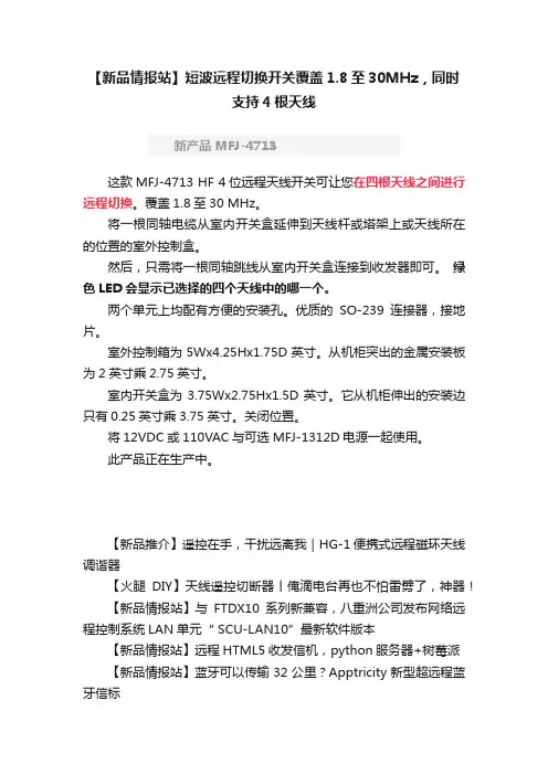
【新品情报站】短波远程切换开关覆盖1.8至30MHz,同时支持4根天线新产品 MFJ-4713这款MFJ-4713 HF 4位远程天线开关可让您在四根天线之间进行远程切换。
覆盖1.8至30 MHz。
将一根同轴电缆从室内开关盒延伸到天线杆或塔架上或天线所在的位置的室外控制盒。
然后,只需将一根同轴跳线从室内开关盒连接到收发器即可。
绿色LED会显示已选择的四个天线中的哪一个。
两个单元上均配有方便的安装孔。
优质的SO-239连接器,接地片。
室外控制箱为5Wx4.25Hx1.75D英寸。
从机柜突出的金属安装板为2英寸乘2.75英寸。
室内开关盒为3.75Wx2.75Hx1.5D英寸。
它从机柜伸出的安装边只有0.25英寸乘3.75英寸。
关闭位置。
将12VDC或110VAC与可选MFJ-1312D电源一起使用。
此产品正在生产中。
【新品推介】遥控在手,干扰远离我|HG-1便携式远程磁环天线调谐器【火腿DIY】天线遥控切断器丨俺滴电台再也不怕雷劈了,神器!【新品情报站】与FTDX10系列新兼容,八重洲公司发布网络远程控制系统LAN单元“ SCU-LAN10”最新软件版本【新品情报站】远程HTML5收发信机,python服务器+树莓派【新品情报站】蓝牙可以传输32公里?Apptricity新型超远程蓝牙信标【无线电史话】1970年载波电流远程HiFi扬声器,附:原理图【新品推介】遥控在手,干扰远离我|HG-1便携式远程磁环天线调谐器【新品情报站】高端电台也玩远程控制 | 八重洲旗舰电台发布远程网络控制单元【新品推介】提升远程操控电台体验感丨ORB电台控制设备:便携式在线远程基础解决方案。
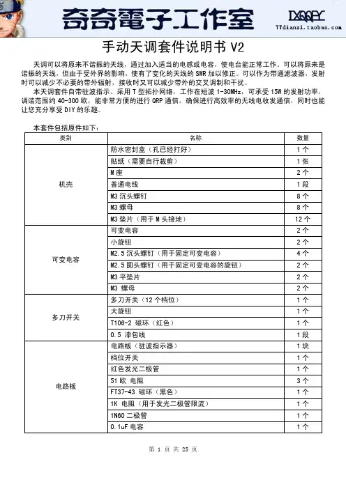
手动天调套件说明书V2天调可以将原来不谐振的天线,通过加入适当的电感或电容,使电台能正常工作。
可以将原来是谐振的天线,但由于受外界的影响,使有了变化的天线的SWR加以修正。
可以作为带通滤波器,发射时可以减少不必要的带外辐射,接收时又可以减少带外的交叉调制和干扰。
本天调套件自带驻波指示、采用T型拓扑网络,工作在短波1-30MHz,可承受15W的发射功率,调谐范围约40-300欧,能非常方便的进行QRP通信,确保进行高效率的无线电收发通信,同时也能让您充分享受DIY的乐趣。
本套件包括原件如下:类别 名称 数量机壳 防水密封盒(孔已经打好) 1个 贴纸(需要自行裁剪) 1张 M座 2个 普通电线 1段 M3沉头螺钉 8个 M3螺母 8个 M3垫片(用于M头接地) 12个可变电容 可变电容 2个 小旋钮 2个 M2.5沉头螺钉(用于固定可变电容) 4个 M2.5圆头螺钉(用于固定可变电容的旋钮) 2个 M3平垫片 2个 M3 螺母 2个多刀开关 多刀开关(12个档位) 1个 大旋钮 1个 T106-2 磁环(红色) 1个 0.5 漆包线 1段电路板 电路板(驻波指示器) 1块 档位开关 1个 红色发光二极管 1个 51欧 电阻 3个 FT37-43 磁环(黑色) 1个 1K 电阻(用于发光二极管限流) 1个 1N60二极管 1个 0.1uF电容 1个一、原理图动手制作之前,请仔细查阅这张图。
1、电路图如下:二、制作过程1、制作之前,请准备好烙铁、焊锡丝、剪刀、小刀、万用表等工具。
并根据原件表核对原件。
2、去除外壳内部多余塑料柱,位于下图的下方,建意先使用斜口钳子将塑料柱去剪掉,再使用电烙铁将多余部分烫平(注意不要烫太长时间,防止将整个塑料烫化,影响正面效果)。
3、安装两个M头到机壳。
安装过程中需要注意6个垫片的位置,它们的作用是理好的接地连接。
4、裁剪贴纸,贴于壳上。
效果图如下:两侧文字部分需要裁剪:5、安装可变电容及旋钮到外壳。
1.ScopeThis specification applies to the MARUWA MWSL1204 GPS L1 active antenna, which in addition to the basic MWSL1204 form can be supplied in two optional forms: MWSL1204R supplied with a loosely fitting black radome cap/cover for external use and MWSL1204SB supplied with a loosely fitting plastic sleeve for internal use.2.SpecificationsMinimum Typical Maximum UnitPart Number MWSL1204 (MARUWA dwg No: MEFP12040268140101)Type Dielectric-loaded Quadrifilar HelixConnector Type Refer to embedding information / connection diagramsFrequency 1573.421575.421577.42MHzPolarisation Right-hand Circular PolarisedVoltage (+ve to co-ax centre-wire). 1.83 3.6VCurrent 3.1 3.4 3.9mAGain (no ground-plane)+15+16dBic at zenithBeamwidth >115DegreesBandwidth (3dB)15MHzAxial Ratio <2.0at zenithVSWR <2.0:1 2.3:1Impedance 50OhmsNoise Figure 0.80.9dBInput 3rd Order Intercept Point -7dBmOperating Temperature -40+20+85°C Overall Dimensions Refer to mechanical drawings mmWeight (excl radome or sleeve)7.0grams3.DimensionsBasic MWSL1204 form:Rev.Date Description Approved Checked PreparedO.Leisten K.Inagaki F.Frimpong 0103 Feb. 2015Issue of the first edition Product Specification (Preliminary)MARUWA Antenna ProductsDocument №MEPS-12040042150101MWSL1204Notes:1.MARUWA Europe assembly drawingMEFP12040268140101 applies.2. Units in mm.3. For connection layout and pad-size, through-hole and connector details please refer to padlayout and designation definitions.MWSL1204R form with loosely fitting black radome cap.MWSL1204SB form with loosely fitting translucent sleeve.Rev.Date Description Approved Checked PreparedK.Inagaki F.Frimpong O.Leisten 0103 Feb. 2015Issue of the first edition Notes:1.MARUWA Europe assembly drawingMEFP1204R268140101 applies.2. Units in mm.3. Black cap/radome unit: METC120X0158140101shown fitted but actually shipped separately.4. For connection layout and pad-size, through-hole and connector details please refer to padlayout and designation definitions.Notes:1.MARUWA Europe assembly drawingMEFP1204S278140101 applies.2. Units in mm.3. Translucent sleeveunit: METC120X0198140101shown fitted but actually shipped separately.4. For connection layout and pad-size, through-hole and connector details please refer to padlayout and designation definitions.4.Product DescriptionTypical Gain PatternThe MWSL1204 GPS L1 miniature high-gain active dielectric-loaded antenna uses MARUWA’sdistinctive materials technology to provide unrivalled circularly-polarised gain from a uniquely small volume. It enables excellent GPS performance in tightly integrated devices that require good positional accuracy.By combining a high-quality dielectric antenna with a high-performance low-noise amplifier the MWSL1204 active antenna provides an excellent solution wanting an active gain input.The MWSL1204 antenna has a sharp filtering response and is particularly suitable for applications where:*The device is hand-held, body-worn, or otherwise surrounded by materials of high relative dielectric-constant which would de-tune other antennas.* The antenna is installed in close proximity to other antennas sharing the same device housing and ground-plane: for example Bluetooth®, WiFi, LTE,WiMax and other cellular radio antennas.* The antenna must fit into a very small installation volume with close proximity to other components and little or no space available for a ground-plane.* The GPS receiver requires 20dB or more of input pre-amplification.* The device is noisy and requires low-noise front-end amplification to achieve the required GPS sensitivity.* Excellent performance with extremely low power consumption.* The orientation of the device is random.* The antenna must be embedded into the device.The MWSL1204 antenna is balanced, which isolates it from the device ground enabling it to reject common-mode noise present on the device ground-plane. The construction and materials of the antenna constrain its near-field region to occupy a very small volume so that materials near theantenna cause negligible de-tuning effects. Therefore the antenna maintains its pattern and efficiency in the presence of dielectric loading. The MARUWA MWSL1204 dielectric-loaded antenna also has a useful filtering fuction as the antenna strongly attenuates signals from the cellular and ISM frequency bands.-96-90-84-10-5051015200611172328343945515662687379849096101107113118124129135141146152158163169174180186191197203208214219225231236242248253287293298304309315321326332338343349354Azimuth Gain (G φ) for Elevation (θ)Low Noise Amplifier Characteristics.Wide-band Frequency ResponseAntenna Integration Options Pad Number Function 1Ground 2RF Out, DC In 3GroundDimensions mm 0.1A 5.0B 2.1C 5.75D 2.8E 4.0F 6.2G3.3H9.5J3.1K 3.0Pad Layout and Pad DesignationsRev.Date Description Approved Checked PreparedK.Inagaki F.Frimpong O.Leisten 0103 Feb. 2015Issue of the first edition MWSL1204 antennas may be mounted externally (order MWSL1204R version) orembedded within a device (order MWSL1204SB version). The product is designed to tuneto the correct frequency when the sleeve or radome-cap is fitted. In thecase of externalmounting the device housing should be designed to seal around the radome-cap groove inorder to provide mechanical support. When internally mounted the sleeve should befitted and the antenna can be fitted into a corner cut-out in the device PCB. Adjacentmetal ground-surfaces (PCB ground-layers or screening cans) can uplift the radiationefficiency compared with the antenna operating separately in free-space. For optimumperformance the gap between the antenna and the copper edge of the PCB ground-planeshould be greater than 5mm. MARUWA can provide application notes with integrationguidance. Please contact your MARUWA sales representative for this information.123AC C B DE D EF HJ KGOrdering Guide for the MWSL1204 AntennaMaruwa can supply three options. Please order according the the following table:Please note that when MWSL1204R or MWSL1204SB are ordered the radome or sleeve parts shall be deliveredin separate packaging and will not be fitted to the MWSL1204 product. The radome and sleeve parts are designed to fit loosely.5.Notes1. The contents of this document assure the characteristics and quality of the antenna components themselves.2. Please ensure that they work correctly in the installed configuration and method of use of your equipment.。
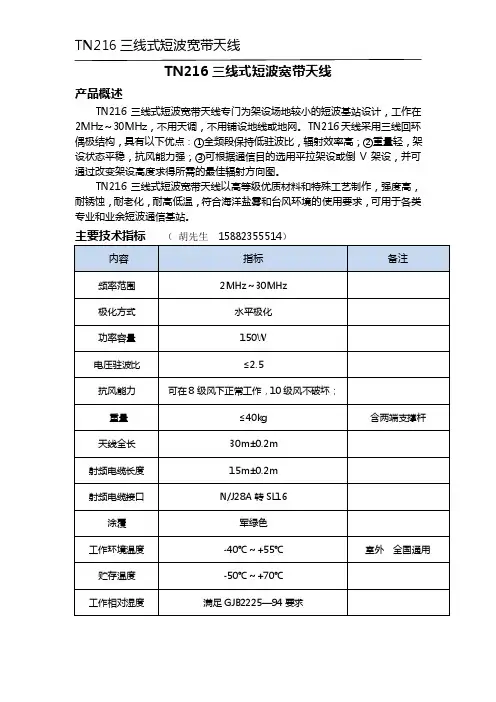
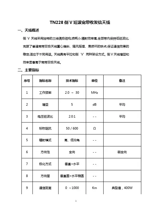
TN216三线式短波宽带天线
产品概述
TN216三线式短波宽带天线专门为架设场地较小的短波基站设计,工作在2MHz~30MHz,不用天调,不用铺设地线或地网。
TN216天线采用三线回环偶极结构,具有以下优点:①全频段保持低驻波比,辐射效率高;②重量轻,架设状态平稳,抗风能力强;③可根据通信目的选用平拉架设或倒V架设,并可通过改变架设高度求得所需的最佳辐射方向图。
TN216三线式短波宽带天线以高等级优质材料和特殊工艺制作,强度高,耐锈蚀,耐老化,耐高低温,符合海洋盐雾和台风环境的使用要求,可用于各类专业和业余短波通信基站。
主要技术指标(胡先生158****5514)
3 组成及工作原理
3.1天线组成见表1:
3.2 工作原理
平拉方式主要用于远距离定向通信,方向图与普通双极天线不同,天线宽边方向辐射最强,窄边方向也有辐射(普通双极天线窄边无辐射)。
频率10MHz以上低仰角呈强方向性,配用125W电台经验定向通信距离达2000km。
10MHz 以下高仰角方向图接近圆形,0km~300km全向无盲区,同时也支持1500km 以内定向通信。
架杆高度取1/4波长为宜,例如在8MHz~12MHz工作,高度约10m~12m。
通信距离很远时使用更高频率,应适当提高架杆高度。
图1 天线平拉架设俯视方向图。

手持式测向天线使用说明书1、简述手持式测向天线是一种小型化的手持式测向天线,利用天线的方向性对大信号进行测向,采用比幅大音点测向方式,设计有直通和放大两种工作方式,扩大了接收信号的动态范围。
该测向天线结构紧凑、体积小、重量轻、方便携带和操作,特别适合户外或野外工作。
由于具有上述特点,使得该测向天线在复杂的城市环境或其它复杂的地形环境下查找辐射源有突出的方便性和灵活性。
2、设备组成手持式测向天线主要由环天线、对数周期天线和手柄控制器组成。
通过操作手柄控制器可以灵活地选择测向天线工作在直通或放大状态。
3、技术参数3.1天线频率范围ANT1 30MHz~200MHzANT2 200MHz~500MHzANT3 500MHz~1000MHzANT4 1000MHz~3000MHz3.2前后比:≥10dB3.3射频接口:N型,50Ohms3.4电源:手柄控制器:4节1.5V AA type NICD batteries4、操作说明4.1手柄控制器说明a:信号放大/不放大开关 按下开关,对由天线来的信号进行放大,释放后不放大。
b:背景灯开关按下开关,电压指示表头的背景灯点亮,释放后熄灭。
c:电压检查开关按下开关,电压指示表头指示手柄控制器内电池的电压,释放后指示表头恢复到零位。
d:按压柱天线推入手柄控制器后弹起,更换天线时用拇指和中指分别按压两个柱子,以解除对天线的锁定。
e: 电压指示表f:电池腔电池腔内安装有(4)1.5V AA 型电池。
4.2基本操作a:安装及连接选择适合工作频率的测向天线,并将其推入手柄控制器,听到“咔”的一声后表示连接到位,手柄控制器的输出插头与测向终端的天线输入口相连接。
天线与手柄控制器的连接过程操作示意图如下。
a b c .e db:测向方法在复杂的地理环境或建筑物密集的城市等场所进行测向,应采用搜索逼近的方式进行。
即在确定了信号的大致方向后,操作人员应逐步向信号最强的方向以搜索逼近的方式移动,在逼近的过程中应随时监视信号强度的变化情况。
M-409、M-527短波天线使用说明书M-409短波天线是一款工作在3.5MHz、7 MHz、14 MHz、21 MHz、29 MHz的五波段缩短型短波天线,3.5MHz、7 MHz、21 MHz共用一对振子,14 MHz、29 MHz 用一对振子,最长的一对振子长度小于20米,因此适合在较小的场地、空间工作。
而M-527短波天线则是一款工作在业余黄金频段的7 MHz、14 MHz、21 MHz 三波段缩短型短波天线,只用一对振子长度约10米。
1. M-409、M-527短波天线线圈及BALUN的使用建议因成都没有北方严寒,南方的酷暑,所以M-409、M-527没有经过严格的考验,为了避免灾难的发生,请注意以下几点。
(1)水平架设时,请用撑竿给BALUN支撑。
(2)倒V架设时,请别用振子当拉绳。
(3)请别把振子绷得像弓弦一样紧。
(4)请用绝缘板给BALUN做一个拉力扩展板。
(5)在刮大风,用较粗的导线做振子,严寒的冬季天线上结有冰凌时,线圈会承受不住巨大的拉力而损坏,请用绝缘板为陷波线圈做一个拉力扩展板,分担线圈承载的拉力。
2.天线导线的选择理论上,任何能够支撑住本身重量的导线都可用于制作天线。
为了使天线能正常工作,在选择导线时,应考虑到:“在有拉力时,这种线会不会变长,从而改变它的频率呢?冬天结了冰之后,它能否经得住?它的绝缘层是否容易坏?”另外,应该避免使用细导线,因导线越细,天线对频率的变化就越敏感。
因此,天线导线不仅必须有抗拉的特性,而且还必须经得起冰的重力和狂风的袭击。
在选择制作天线的导线时,请大家记住下面几条原则:(1)粗导线比细导线好;(2)绝缘导线比裸导线好;(3)硬铜线比软铜线好;(4)多股导线比单股导线好(射频电流只沿导线的外表层传导)。
3.M-409、M-527短波天线架设前的准备感谢您使用M-409、M-527短波天线,天线各部分请见图。
M-409、M-527各波段的振子长度分别是M-409天线:A段3.7m (M-527天线J段3.7m)2根,B段4.2m (M-527天线K段0.8m )2根,C段2.8m (M-527天线L段1.4m)2根,D段2.8m 2根,E 段1.4m 2根,以上包括打结、折返等安装尺寸。
天线共用器使用维护说明书绵阳市泰星科珑电子有限责任公司一. 前言本手册对泰星科珑天线共用器的功能、安装与操作程序、注意事项以及维护方式作详细说明。
请在启用本产品进行安装调试前,务必详细阅读本手册。
二. 产品说明1.功能特点及用途天线共用器适用于短波传输系统中,将天线接收的信号经过放大后、分配为8路输出,输出的信号送到8台接收设备,使系统中的天线的数量得到减少。
该设备的供电电压为AC220V ,当不给天线共用器供电时可以自动转换到应急状态(应急状态时各个端口的输出电平较正常状态工作时低,)。
(1)天线共用器的射频放大采用低噪声MMIC 电路;该类芯片选用美国著名公司安捷伦产品,保证了整机的高性能指标及高可靠性。
(2)采用独特的自动切换功能,使天线共用器可以在正常供电及断电的的情况下工作。
(3)整机采用开关电源供电,温升小,适应电压范围宽。
(4)19英寸标准机架设计,安装使用方便。
2.天线共用器原理框图见图1RF放大输出8输出1RF 分配器输入避雷器图1:天线共用器原理框图3.天线共用器性能参数见表1序号 项目 单位 性能参数 备注1 频率范围 MHz2 ~ 30 2 频率响应 dB ±13 增益调节范围 dB 0 ~ 104标称增益dB≥10正常状态5 插入损耗 dB ≤10 应急状态6 噪声系数 dB ≤2.57 反射损耗 dB ≥18(输出) ≥14(输入)8 工作温度范围℃ -5 ~ +55 9 接口——L16-50Ω4. 天线共用器面板功能及内电路板功能简图如下(1)前面板功能简图绵阳泰星科珑电子有限公司TFP8-1天线共用器0TESINIC泰星科珑3211. 电源开关 2. 电源指示灯 3. 增益调节旋钮(2) 后面板功能简图输出8输出7输出6输出5输出4输出3输出2输出1输入1. 电源插座 2. 机器编号 3. 天线共用器输入 4. 天线共用器输出(共8组)三. 安装使用注意事项1. 在将连接线安装到天线共用器的输入输出端口前,务必作好标记并记录备案。
中、短波广播接收天线的配置和使用作者:董涛来源:《大陆桥视野·下》2013年第01期摘要天线是一种高频电能与电磁波能的转换器,是无线电通信系统重要的前端器件,其本身的质量直接影响着无线电系统的整体性能。
本文阐述了中、短波广播接收天线的使用与监测工作的内在联系,对原有监测台和新建监测台各种天线的技术特点进行了比较,阐述了天线的使用方法和注意事项。
关键词天线广播监测电气特性天线使用一、前言监测台使用接收天线的目的,是通过接收天线的技术特性的运用达到预期的效果,使接收信号最强,降低干扰,从而提高信噪比。
因此,天线性能的好坏,直接关系到监测工作完成的质量,同时,科学、合理的使用天线,对更好地完成监测工作、提高监测工作的效率同样具有重要的作用。
二、监测任务与天线选择接收中、短波段广播电台的信号是监测台的基本任务之一,按要求分别进行如下工作:广播效果的评估;播出质量的监听;发射特性的测量;境外电台广播动态的监测;频谱监测。
根据各项监测任务的不同要求,监测台需配置不同形式的接收天线。
进行播出质量的监听和发射特性的测量,要求有足够强的接收信号,便于判别播出异态和避开同频道上其他发射机的干扰,以便准确测量发射机的发射特性(调幅度、频偏容限度)。
进行境外电台广播动态的监测,也同样需要足够强的接收信号,对电台的归属进行辨别,特别是对一些弱信号电台,尽可能通过高性能天线,提高信号强度,对确保准确、及时地发现频率的变化具有重要作用。
进行上述项目的监测,要求接收天线具有方向性强、增益系数高的特点。
评估广播效果则需要用全向天线接收信号。
因为,广播宣传的服务对象是广大的普通听众,而普通听众使用的是民用接收机,若使用监测台强定向、高增益的天线接受的电台信号,不能准确反映收测地区实际的广播效果。
因此,应用最接近民用接收机收听效果的全向天线来评估广播的实际效果。
频谱监测主要是掌握监测台所在地区上空的中短波波段的频谱负荷情况,需要同时比较来自不同方向的电台信号在接收地区的强弱程度,要用全向天线来客观评定各频道的负荷程度。
M-409、M-527短波天线使用说明书M-409短波天线是一款工作在3.5MHz、7 MHz、14 MHz、21 MHz、29 MHz的五波段缩短型短波天线,3.5MHz、7 MHz、21 MHz共用一对振子,14 MHz、29 MHz 用一对振子,最长的一对振子长度小于20米,因此适合在较小的场地、空间工作。
而M-527短波天线则是一款工作在业余黄金频段的7 MHz、14 MHz、21 MHz 三波段缩短型短波天线,只用一对振子长度约10米。
1. M-409、M-527短波天线线圈及BALUN的使用建议因成都没有北方严寒,南方的酷暑,所以M-409、M-527没有经过严格的考验,为了避免灾难的发生,请注意以下几点。
(1)水平架设时,请用撑竿给BALUN支撑。
(2)倒V架设时,请别用振子当拉绳。
(3)请别把振子绷得像弓弦一样紧。
(4)请用绝缘板给BALUN做一个拉力扩展板。
(5)在刮大风,用较粗的导线做振子,严寒的冬季天线上结有冰凌时,线圈会承受不住巨大的拉力而损坏,请用绝缘板为陷波线圈做一个拉力扩展板,分担线圈承载的拉力。
2.天线导线的选择理论上,任何能够支撑住本身重量的导线都可用于制作天线。
为了使天线能正常工作,在选择导线时,应考虑到:“在有拉力时,这种线会不会变长,从而改变它的频率呢?冬天结了冰之后,它能否经得住?它的绝缘层是否容易坏?”另外,应该避免使用细导线,因导线越细,天线对频率的变化就越敏感。
因此,天线导线不仅必须有抗拉的特性,而且还必须经得起冰的重力和狂风的袭击。
在选择制作天线的导线时,请大家记住下面几条原则:(1)粗导线比细导线好;(2)绝缘导线比裸导线好;(3)硬铜线比软铜线好;(4)多股导线比单股导线好(射频电流只沿导线的外表层传导)。
3.M-409、M-527短波天线架设前的准备感谢您使用M-409、M-527短波天线,天线各部分请见图。
M-409、M-527各波段的振子长度分别是M-409天线:A段3.7m (M-527天线J段3.7m)2根,B段4.2m (M-527天线K段0.8m )2根,C段2.8m (M-527天线L段1.4m)2根,D段2.8m 2根,E 段1.4m 2根,以上包括打结、折返等安装尺寸。