电容测试条件(经典)
- 格式:pdf
- 大小:297.94 KB
- 文档页数:19
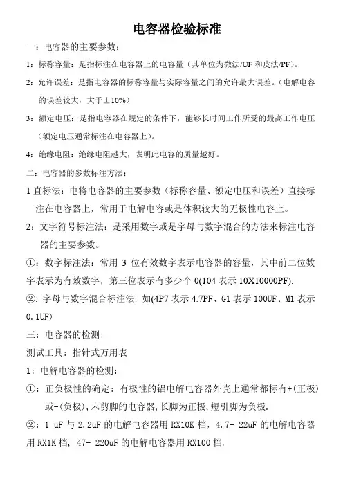
电容器检验标准一:电容器的主要参数:1:标称容量:是指标注在电容器上的电容量(其单位为微法/UF和皮法/PF)。
2:允许误差:是指电容器的标称容量与实际容量之间的允许最大误差。
(电解电容的误差较大,大于±10%)3:额定电压:是指电容器在规定的条件下,能够长时间工作所受的最高工作电压(额定电压通常标注在电容器上)。
4:绝缘电阻:绝缘电阻越大,表明此电容的质量越好。
二:电容器的参数标注方法:1直标法:电将电容器的主要参数(标称容量、额定电压和误差)直接标注在电容器上,常用于电解电容或是体积较大的无极性电容上。
2:文字符号标注法:是采用数字或是字母与数字混合的方法来标注电容器的主要参数。
①:数字标注法:常用3位有效数字表示电容器的容量,其中前二位数字表示为有效数字,第三位表示有多少个0(104表示10X10000PF).②: 字母与数字混合标注法: 如(4P7表示4.7P F、G1表示100UF、M1表示0.1UF)三: 电容器的检测:测试工具: 指针式万用表1: 电解电容器的检测:①: 正负极性的确定: 有极性的铝电解电容器外壳上通常都标有+(正极)或-(负极),末剪脚的电容器,长脚为正极,短引脚为负极.②: 1 uF与2.2uF的电解电容器用RX10K档,4.7- 22uF的电解电容器用RX1K档, 47- 220uF的电解电容器用RX100档.3:测试方法:1: 电解电容器的检测:①:根据电解电容器上所标示的容量,将万用表置于合适的量程,将二表短接后调零.黑表接电解电容的正极,红表接其负极,电容器开始充电, 万用表指针缓慢向摆动,摆动到一定的角度后,(充电结束后)又会慢慢向左摆动(表针在向左摆动时不能摆动到无穷大的地方)指针向左摆动后所指示的电阻会大于500K,若电阻值小于100K,则此电容器不合格.②: 将二表对调后测量,正常时表针应立即向右摆动后向左摆动(摆动的大小应大于第一次的大小),且反向电阻应大于正向电阻.若测量电容时表针不动或第二次测量时表针的摆动大小小于第一次测量时的大小,则此电容器不合格.③: 若测量电解电容器的正反向电阻时阻值都为0,则此电容器不合格. 2: 小容量电容器的检测:①:用万用表RX10K档测量其二端的电阻值应为无穷大,若测得一定的电阻值或阻值接近0,则此电容器不合格。
22uf贴片陶瓷电容的测试条件1. 介绍在电子产品生产过程中,贴片电容作为电子元件中的重要部分,也需要进行严格的测试,以确保其性能和可靠性。
而22uf贴片陶瓷电容作为一种常见的电容型号,其测试条件更是需要谨慎确定,以确保测试结果的准确性和可靠性。
2. 测试条件的重要性贴片陶瓷电容作为电子产品中常用的一种被动元件,其性能直接影响到整个电路的稳定性和可靠性。
确定合适的测试条件对于保证贴片陶瓷电容的质量至关重要。
通过正确的测试条件,可以有效地检测出电容的性能特征,从而保证电子产品的品质。
3. 测试条件的确定在确定22uf贴片陶瓷电容的测试条件时,需要考虑以下几个方面:3.1 温度温度是影响电容性能的重要因素之一,过高或过低的温度都会对电容的性能产生影响。
在测试22uf贴片陶瓷电容时,需要确定合适的温度范围以及温度变化的测试条件。
3.2 电压22uf贴片陶瓷电容在电路中通常承受不同的电压,因此需要在测试中确定合适的电压范围,并进行相应的电压稳态和脉冲电压的测试。
3.3 频率对于陶瓷电容来说,频率也是一个重要的测试条件,因为在实际的电路中,电容往往会受到不同频率的信号作用,因此需要确定合适的频率范围进行测试。
3.4 电容值测量22uf贴片陶瓷电容的电容值是其重要的性能特征之一,因此在测试中需要确定合适的电容值测量条件,以保证测试结果的准确性。
4. 测试方法在确定了测试条件后,还需要选取合适的测试方法,以保证测试的准确性和可靠性。
常见的测试方法包括:4.1 静态测试静态测试是指在固定的测试条件下对电容进行稳定状态下的测试,如电容值、漏电流等参数的测量。
4.2 动态测试动态测试是指对电容在不同频率、温度和电压条件下进行测试,以模拟实际工作环境中的电容性能。
4.3 老化测试为了验证电容的可靠性,可以进行老化测试,即在一定条件下对电容进行长时间的工作,以检测其性能是否稳定。
5. 结论22uf贴片陶瓷电容作为电子产品中常用的一种被动元件,其测试条件的确定对于保证产品质量和可靠性至关重要。
超级电容器测试电压窗口从开路电位到电压窗口的值的2倍作为两电极的电压窗口最合适。
如果是对称电极,你需要在三电极体系下先测出开路电位,从开路电位到电压窗口的值的2倍作为两电极的电压窗口最合适。
但是一般情况下,直接选择三电极的电位差作为窗口。
如果是不对称电极,需要测试窗口电压,一般不超过正极负极窗口电压之和。
但是考虑到过极化的问题,一般从一个窗口开始扫,逐步加大电压,当cv比较开始翘的时候证明开始发生不可逆的氧化还原反应,就不要往上扫了。

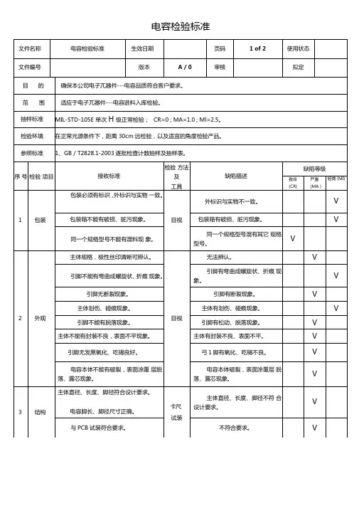
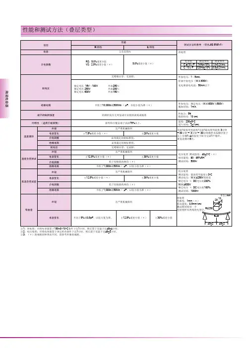
电容检验(jiǎnyàn)规范(1)电容(diànróng)检验规范(1)物料名称电解电容物料类别电子类供应商参考《合格供应商目录》序号检验项目技术要求/缺陷内容检验方法检验工具不合格分类抽验判定检验水平1包装质量1.内外包装标示清晰明确,包括供应商名称,规格型号,批号,数量,生产日期;2.外包装应牢固,无破损,变形。
具有良好的防潮,防压及防腐蚀等。
用肉眼观察目测外观质量1.引出线应光亮、清洁,无脱锡、露铜、露铁、生锈、黑斑及明显水迹;表面无尖角毛刺、损伤、夹层、氧化现象;引出线不得有废针、弯针;2.外表无可见损伤:变形、无凹陷,无突起;没有混料的现象;用肉眼观察目测2外形尺寸1.本体长、宽,引脚直径和脚距,应与BOM要求或者零件规格书要求或者样品相符;用游标卡尺测量游标卡尺2.引脚间距要与PCB板一致。
将物料插入PCB板进行试装PCB板3电气性能容值要与物料清单规格要求一致。
在1KHz下,用电桥测试容量数字电桥4引脚强度引脚受力弯曲后,无断裂、和本体无松动或脱落,电气性能符合第3项。
任取一根引脚按相反的方向连续弯曲两次(共四次)后,用肉眼观察和电桥测试。
目测/数字电桥5安全性能耐压施加额定电压,电容本体应无弯化,各项性能参数符合《规格表》用耐压测试仪在电容两端施加125%额定电压耐压测试仪6漏电流漏电流值应满足I≤(0.03×C×U)/1000,式中C为电容量,U为额定电压,0.03为常数。
(电解电容需要测试此项)漏电流测试仪额定电压下测试漏电电流漏电流测试仪7高温测试高温试验后,外观应无可见损伤,性能符合要求。
(瓷片电容除外)放在温度105±5℃的恒温箱中超过4h后检测。
恒温箱8低温测试低温试验后,外观应无可见损伤,性能符合要求。
(瓷片电容除外)放在温度-24±5℃的冰箱中超过24h后检测。
冰箱检验要求及注意事项:附录(f ùl ù)A贴片电阻/电容(di ànr óng)规格表1.以上检验项目可参考《合格供应商项目》、《电板物料清单》、《供应商的选型手册》。
Capacitance and Dissipation FactorMeasurement ofChip Multilayer Ceramic CapacitorsPage1. Introduction--------------------------------------------------------------12. Characteristics of Chip Multilayer Capacitors-------------------12-1. Temperature Characteristic2-2. Voltage Characteristic(1) AC Voltage Characteristic(2) DC Bias Characteristic2-3. Frequency Characteristic2-4. Summary3. LCR Meters and Measurement Jigs-------------------------------63-1. LCR Meters3-2. Measurement Jigs4. LCR Meter Measurement Principle--------------------------------74-1. Measurement Principle4-2. Measuring Voltage4-3. Capacitance Measurement Circuit Mode5. Capacitance Measurement by LCR Meter 4284A--------------106. Capacitance Measurement by LCR Meter 4278A--------------147. Closing--------------------------------------------------------------------18References------------------------------------------------------------------18Murata Mfg. Co., Ltd.TD No.C10E1. IntroductionWhen you measure a high dielectric MLCC capacitor (X7R-characteristic or Y5V-characteristic) using a LCR meter, there may be a case you can not obtain a reasonable capacitance value within its nominal range.As capacitance and dissipation factor of these Temperature characteristic MLCC capacitors significantly change according to the measurement temperature, voltage (AC, DC) andfrequency. One of the reasons of such a failure to obtain a reasonable capacitance can be that your have not performed the measurement correctly using specified measurement conditions.Another reason may be an incorrect meter setting or use of measurement equipment that does not have the capability needed for accurate measurement.Solutions for the former issue is to fully understand characteristics of MLCC capacitors and the appropriate “three (3) measuring conditions”, i.e. measuring temperature, voltage (AC and DC) and frequency. The actual measurement conditions of capacitance and dissipation factor of high dielectric ceramic capacitors are shown in Table 1 below.The temperature used for these conditions is 25 degree:Table 1 Measuring ConditionsNominal Capacitance Measuring Frequency Measuring VoltageC ≤ 10µF (10V or greater) 1 ± 0.1kHz 1.0 ± 0.2VrmsC ≤ 10µF (6.3V or less) 1 ± 0.1kHz0.5 ± 0.1VrmsC > 10µF120 ± 24Hz0.5 ± 0.1VrmsThe solution for the second issue is to understand the capability of the measurement equipment to be used and to confirm that it meets the measurement conditions listed in Table 1.In this brochure, we will first describe the characteristics of the MLCC capacitors that can affect capacitance and dissipation factor measurement. Next, the measuring principle of the LCR meters used for actual measurement is described, then an example of the correct method used to measure the capacitance and dissipation factor of the MLCC capacitors is explained.2. Characteristics of the MLCC (Multilayer Ceramic Chip) CapacitorsThe MLCC capacitors have excellent features such as small size, high reliability, lowimpedance and no-polarity, etc., but on the other hand, they have demerits such as capacitance change with temperature or voltage change.In the following sections, measurements of 1206 type 10µF X7R-characteristic and Y5V-characteristic MLCC capacitors are taken up as examples to explain the various characteristics that can affect the measurement of capacitance and dissipation factor.2-1. Temperature CharacteristicTemperature characteristics of MLCC capacitors are shown in Fig.1 below:At the measurement conditions of 1kHz, 1Vrms, whereas capacitance change ratio of the X7R-characteristic is within ± 10% at maximum, The Y5V-characteristic capacitor is allowed to over a wider range of + 30% / -80%. Dissipation factor also changes according to measurement temperature, which tends to go up in lower temperatures for both X7R- and Y5V- characteristic capacitors.(a) Capacitance Change Ratio(b) Dissipation Factor (DF)Fig.1 Temperature Characteristic(1) AC Voltage CharacteristicThe AC voltage characteristics of X7R- and Y5V-characteristic MLCC capacitors are shown in Fig.2 below:At the measurement conditions of 25 degree, 1kHz, while capacitance change ratio of the X7R-characteristic capacitors is within ± 5% at maximum, the capacitance of Y5V-characteristic capacitors drops by 50% at the maximum and changes according to applied AC voltage level.Although the dissipation factor of Y5V-characteristic capacitor also changes significantlyaccording to the measurement voltage, the X7R-characteristic capacitor shows very little change.(a) Capacitance Change Ratio(b) Dissipation Factor (DF)Fig.2 AC Voltage CharacteristicThe DC bias characteristics of X7R- and Y5V-characteristic MLCC capacitors are shown in Fig.3 below:At the measurement conditions of 25 degree, 1kHz, 1vrms, the capacitance of the X7R-characteristic capacitor drops by a maximum of 60% according to DC bias voltage applied, while the capacitance of the Y5V-characteristic capacitor drops as much as 90%.The capacitance of MLCC capacitors decreases as applied DC bias voltage increases. Also dissipation factors of those capacitors comes down as DC bias voltage goes up.(a) Capacitance Change Ratio(b) Dissipation Factor (DF)Fig.3 DC Bias Characteristic2-3. Frequency CharacteristicThe frequency characteristics of X7R- and Y5V-characteristic MLCC capacitors are shown in Fig.3 below:Although capacitance of both X7R- and Y5V-characteristic capacitors changes little as the measurement frequency is altered, their dissipation factors change substantially according to the measurement frequency. The reason the Y5V-characteristic capacitor’s capacitance drops lower than 50% is that generally it is not possible to apply 1Vrms with the usual impedance analyzer(e.g. LCR meter) to the Y5V -characteristic capacitor at these (shown) frequency steps and0.1Vrms is used instead. At the AC measurement voltage of 0.1Vrms, the capacitance of Y5V-characteristics decreases by 50% as shown in Fig.2 (AC Voltage Characteristic.)(a) Capacitance Change Ratio(b) Dissipation Factor (DF)Fig.4 Frequency Characteristic2-4. SummaryAs described above, the capacitance and dissipation factors of MLCC capacitors change according to the measurement temperature, AC voltage, DC bias and frequency. Therefore, the capacitance and dissipation factor of these capacitors shall be measured after specifying the three measurement conditions, “temperature”, “voltage (AC & DC)” and “frequency”. When you design an electronic circuit using these capacitors, use them after carefully considering their characteristic values at the intended environment and operating conditions.3. LCR Meters and Measuring JigsTypical LCR meters and measurement jigs are introduced in this section.3-1. LCR MetersLCR meters are generally used for measurement of the capacitance and dissipation factor of capacitors. Typical LCR meters include 4284A, 4278A and 4268A by Agilent Technologies Corp.as shown in Fig.5. As there are some measurement instruments that do not meet themeasurement conditions specified in Table 1, please review the measurement principles in Section 4 and measurement methods in Section 5 and 6 before performing any tests.(a) 4284A(b) 4278A(c) 4268AFig.5 Exterior Photographs of LCR Meters3-2. Measuring JigsIt is necessary to select a measurement jig appropriate the LCR meter to be used. Typical measurement jigs used for MLCC capacitors are shown in Fig.6 below:(a) 16034E (b) 16334AFig.6 Appearance Photographs of Measuring JigsThere are two types of measurement jigs, a type on which a chip capacitor is placed and measured by applying a pin to one-side of the electrode terminal, such as 16034E of Agilent Technologies Corp. and another type that is shaped like tweezers to catch a chip capacitor by its terminals to measure it such as 16334A also from Agilent Technologies Corp.4. LCR Meter Measurement PrincipleThe basic issues necessary for LCR capacitor measurement such as the LCR metermeasurement principle and measuring voltage, etc. are explained in this section.4-1. Measurement PrincipleThe typical “measurement system” of LCR meters is the “automatic balancing bridge method”, which is shown in Fig.7.In Fig.7, a high gain amplifier automatically adjusts the gain level so that an eclectic current is drawn through a resistor. R is always equal to the current flowing through the DUT (Device under Test), that is, the L-side end potential of DUT (lower voltage side) always equal to virtual ground level (electric potential =0). At this condition, impedance value of the DUT can be determined from the out put voltage E2, feedback resistance R and input voltage E1 as follows:Zx=R∗E1/E2E1= |E1| ∠θ1 = |E1|cosθ1+|E1|sinθ1E2= |E2| ∠θ2 = |E2|cosθ2+|E2|sinθ2At this moment, phase angles of E1 and E2, θ1 and θ2, are measured at the same time, and the “resistance component Rx” and “reactance component Xx” can be calculated from the above phase angles and Zx value, from which capacitance and dissipation factor are determined.High gain amplifierFig.7 Principle Diagram of Automatic Balancing Bridge4-2. Measuring VoltageLCR meters generally provide internal resistances to protect their own power supply circuits.Depending on the value of this resistance, the actual voltage differential between the electrodes of a capacitor being measured drops excessively which prevents correct measurement of capacitance and dissipation factor of the capacitor. Depending on type of LCR meter used,measurement of a ceramic capacitor with large capacitance such as 10µF at an assigned voltage may be impossible due to extremely low impedance of such capacitor.This mechanism is explained using the simple equivalent circuit model shown in Fig.8.Measuring voltage is applied to DUT, E dut is a partial potential of power supply voltage E O divided by impedance of DUT, Zx = R + jX, and the LCR meter’s internal impedance R in .The measuring voltage applied to DUT, E dut , is determined by: √(R 2+X 2)E dut =E0∗√{(Rin+R)2+X 2}X=1/ωC=1/(2πfC)Thus, the measurement voltage of capacitor is different from the power supply voltage.Therefore, we recommend using a LCR meter that automatically maintains the “measurement voltage” at a preset voltage (ALC function). When using a LCR meter not providing such function,you have to manually measure actual voltage applied between the terminals of the capacitor being measured, etc. and manually adjust it.Fig.8 Measuring Voltage Applied to DUT4-3. Capacitance Measurement Circuit ModeCapacitance measurement circuit mode generally includes two types of circuit modes.These are; parallel equivalent circuit mode and serial equivalent circuit mode.(1) In case of small capacitance (see Fig.9):A small capacitance has a large reactance, i.e. high impedance, which causes the influence of parallel resistance Rp on the measurement to be far larger than that of the serial resistance Rs, thus Rs can be neglected and measurement circuit provides a parallel equivalent circuit mode.(2) In case of large capacitance (see Fig.10):Internal resistancePowersupplyA large capacitance has a small reactance, i.e. low impedance, which makes the influenceof serial resistance Rs on the measurement far larger than that of parallel capacitance Rp, thus Rp can be neglected and measurement circuit provides a serial equivalent circuit mode.High impedance)Low impedance)Fig.9 Small capacitance Eig.10 Large capacitance(Parallel equivalent circuit mode) (Serial equivalent circuit mode)(3) The measurement circuit mode is determined according to impedance value of a capacitor tobe measured, which is switched at about 10Ω in relation to internal impedance of LCR meter.The relationship between capacitance and impedance is shown in Fig.11. The “Electric Capacitance” (4.7) and “Dielectric Dissipation Factor” (4.8) sections of the public standard JIS C 5101-1-1998 define measurement frequency to 1kHz for 10µF or lower capacitance and to 120Hz for capacitance higher than 10µF. Therefore, the impedances of all these capacitance values become 10Ω or greater, which are measured by the parallel equivalent circuit mode. However, for a capacitance exceeding 10µF, the serial equivalent circuit mode is used, as its impedance is lower than 10µF.][Fig.11 Relation between Capacitance and Impedance5. Capacitance Measurement by LCR Meter 4284AThe correct capacitance measurement method using a typical LCR meter 4284A andmeasurement jig 16034E is described in this section.5-1. Turn on the power of LCR meterThis measurement equipment requires warm-up time. Turn the power on for the meter 30 minutes before starting actual measurement.5-2. Installing the measuring jig on the meterInstall the measurement jig on the meter as shown in Fig.12.5-3. Setting the LCR meterSetup measurement conditions using “Measure Setup” screen (see Fig.13).(1) FUNC Æ Cp-D,(2) FREQ and LEVELÆ See Table 1.Fig.12 LCR Meter with Jig InstalledFig.13 Measure Setup ScreenNote 1: If FREQ and/or LEVEL is not correctly set, you will not be able to correctly measure the capacitance. These settings are explained in the followingexample:Example: Sample capacitor 1812 type X5R-characteristic 100µFCorrect settings for the frequency and AC voltage are “FREQ: 120Hz” and “LEVEL: 0.5Vrms”respectively (see Fig.14). If capacitance is measured using different conditions, such as1kHz and 1Vrms, the capacitance will be incorrectly displayed, as being 20% lower than if measured using the correct conditions as shown in Fig.15.ABC“A” field in the above figure is set to measurement frequency and voltage required. This field is correctly set to “FREQ: 120Hz” and “LEVEL: 500mV” according to the specification. “B” is a field that displays the values of measured capacitance and dissipation factor. The capacitance is about 94µF is compared against the nominal value of 100µF of the sample capacitor, this is within the specified capacitance tolerance. “Vm” in “C”field indicates actual the measurement voltage monitored by the meter, which shows 500mV applied to the sample.Fig.14 Measuring Conditions : 120Hz, 0.5VrmsABC“A” field in the above figure is set to “FREQ: 1kHz” and “LEVEL: 1V”, both of which are different from sample’s specification. The capacitance indicated in “B” field above is very low, about 75µF against nominal value of 100µF of the sample capacitor, which is 20% lower than that measured by the correct conditions.“Vm” in “C” field indicates the actual measurement voltage monitored by the meter, which shows only about 21mv against set value 1V.Fig.15 Measurement Conditions : 1kHz, 1Vrms(3) Hi-PW (High Power) Æ ON, and ALC (Automatic Level Control) Æ ONWhen “Hi-PW” is set to “ON”, the capacitance can be measured with the Power Supply voltage within set to a range of 1Vrms to 10Vrms. ALC is used to maintain the measurement voltage at the designated voltage and shall be always set to “ON”. Even if you set the measurement voltage to 1Vrms, you cannot obtain the correct capacitance value unless the actually monitored value is 1Vrms. This setting is explained using the following example: Example : Sample 1206 type X7R-characteristic 10µFBy setting the ALC and Hi-PW to “ON”, you can apply 1Vrms measurement voltage to a sample to be measured, and obtain a correct capacitance value, which is about 9.86µF in the example (see Fig.16 and 17). When ALC is set to “OFF”, measurement voltage becomes low 184mV in the example figure below, which makes apparent capacitance low, showing about 8.43µF.AB”A” field in the above figure indicates both ALC and Hi-PW being set to “ON”.An asterisk mark at “B” field in the figure means ALC being on.Fig.16 Measure Setup Screen Showing ALC ONBA“Vm” in “A” field in the above figure indicates actual measurement voltage monitored by the meter, which shows 1V being applied to the sample. “B” field shows the capacitance of a 10µF product, which is about 9.86µF which is within the specified tolerance.Fig.17 Measure Setup Screen Showing ALC ONBA“A” field in the above figure indicates ALC being set to “OFF” and Hi-PW being set to “ON”. No asterisk mark at “B” field in the figure means ALC is off.Fig.18 Measure Setup Screen Showing ALC OFFBA“Vm” in “A” field indicates actual measurement voltage monitored by the meter, which shows 1V is applied to the sample. “B” field shows a capacitance of a 10µF product, which is about 9.86µF which is within the specified tolerance.Fig.19 Measure Setup Screen Showing ALC OFFNote 2: Check Method of Measurement Voltage Applied to Capacitor Under Test One method to check the measurement voltage actually applied to a capacitor under test is to apply plus and minus probes of the tester to both terminals respectively of the capacitor set into measurement jig, and read the indicated voltage.A photograph in which “measurement voltage” of Fig.17 above is checked is shown in Fig.10. It shows it indicates a value of 998mVrms.Also, a photograph in which the “measurement voltage” of Fig.19 is checked is shown in Fig.21. It shows the tester indicating 187mVrms and low capacitance due to the AC measurement voltage being less than 1Vrms.TesterFig.20 Tester Measurement Example for ALC ON StateTesteFig.21 Tester Measurement Example for ALC OFF State5-4. CalibrationYou implement the measurement calibration using COMPEN in the MEAS SETUP screen.The are two types of calibration “Short Calibration” and “Open Calibration”,The order in which you preform the calibration is optional.(1) Short CalibrationFor “short” condition, see Fig.22. Confirm that Rs is 0.03 Ω or less at this point. When Rs does not come down to 0.03 Ω or less, then wash the terminal using acetone, repeat above as necessary to obtain a Rs reading of 0.03 Ω or less.(a) 16034E (b) 16334AFig.22 Short Condition(2) Open CalibrationAdjust “open” distance to a size of chip capacitor to be measured. See Fig.23 for “open”condition.(a) 16034E (b) 16334AFig.23 Open Condition5-5. MeasurementYou measure the MLCC capacitors after completing these calibrations.6. Capacitance Measurement by LCR Meter 4278AIn this section, A correct capacitance measurement method using the combination of a typical LCR meter 4278A and measuring jig 1603A is explained.6-1. Turn on LCR Meter PowerThe equipment requires a warming-up time, always turn on its power 30 minutes before starting your actual measurement.6-2. Meter with Measuring Jig installed onInstall the measuring jig on the measuring equipment as shown in Fig.24.Fig.24 Meter with Measuring Jig installed on6-3. Meter SettingSet measurement conditions on the meter using ”Menu” screen shown in Fig.25.(1) Setting items to be measured:MENU ÆMEAS, PARAMETER Æ Cp-D(2) Setting measuring frequency and voltage :MENU Æ SIGMAL, SOURCE Æ FREQ Æ 1kHzÆ OSC Æ 1.0VNote 4: 4278A provides two types frequencies, 1kHz and 1MHz. Therefore, it cannot measure a capacitor having a capacitance greater than 10µFbecause such capacitance requires a measurement frequency of 120Hz.Use 4284A or 4268A for the measurement of a capacitor greater than 10µF.Fig.25 Menu ScreenNote 5: Check Method of Measurement Voltage Actually Applied to a Capacitor Even though you set the measurement voltage to 1Vrms, if “1Vrms” is not actuallyapplied to the capacitor to be measured, you won’t be able to correctly measurecapacitance.Check whether the measurement voltage set is actually applied to the capacitor byapplying plus and minus probes of a tester to both terminals of the capacitor set inmeasuring jig and read a indicated voltage.Fig.26 shows the check operation of the measurement voltage of a 1206 size X7R-characteristic 10µF chip capacitor, in which measurement frequency is set to 1kHZ and measurement voltage to 1Vrms. Actual measurement voltage is about 1.0Vrms andmeasured capacitance is about 10.4µF.Fig.26 Measurement Voltage Check by Tester(3) Cable LengthWhen using measurement jig 16034E, set CABLE LENGTH to “0 (zero)”m.MENU Æ NEXT Æ CABLE LENGTH Æ 0m.6-4. CalibrationUse “screen” displayed after pushing MENU Æ NEXT Æ COMPEN for the calibration.The calibration at this point shall be performed for OPEN, SHORT and TEMP COMP. See LCR meter 4284 measurement procedure in Section 5 herein for OPEN and SHORTcalibration methods.OPEN COMPEN Æ OPEN ONSHOT COMPEN Æ SHORT ONSTD OFFTEMP COMPEN6-5. MeasurementYou can start the measurement of the MLCC capacitors after completing the TEMPCOMPEN above.Note 6: Capacitance Change by Aging CharacteristicAlthough the “aging characteristic” of high dielectric MLCC capacitors is not directly related to the capacitance measurement, as it reduces capacitance of the MLCCcapacitors, you must take it into consideration when designing a circuit using thosecapacitors.High dielectric MLCC capacitors (typically represented by X7R / Y5V temperature characteristic of which main composition is BaTiO3) have an attribute that theircapacitance decreases as time elapses. This attribute is called “aging” of capacitance.Capacitance aging is a phenomenon inherent in dielectric ceramics havingspontaneous polarization. When a ceramic capacitor of this type is heated up over its Curie point and left at a temperature lower that the Curie point with no load, the rotation of its spontaneous polarization is gradually inactivated as time elapses, which is observed from outside as “capacitance decrease”.This phenomenon is not limited to our products but generally observed in all highdielectric MLCC capacitors (with BaTiO3 system). Some public standards have anappendix for supplemental explanation about the aging of electric capacitance (Multilayer Capacitor: IEC 384-10 Appendix X7R, etc.) If a MLCC capacitor with aging-reduced low capacitance is again heated up over its Curie point, its capacitance is restored to nominal again the aging process from the time point it is cooled down to a temperature lower than the Curie point starts again.Generally, using a capacitance value reading 24 hours after heat-treatment at 150 degree or higher as a baseline, the capacitance linearly decreases according to logarithm time scale.See a typical example of a capacitance aging characteristic graph decreasing with time shown in Fig.27.Fig. 27 Aging Characteristic, Capacitance Change with TimeWhen you use high dielectric MLCC capacitors, please carefully consider thecapacitance change of these capacitors arising from their aging characteristics, and particularly when you need a stable capacitance, check capacitors using your actual appliances. However, temperature compensating type MLCC capacitors have no such aging characteristic.7. ClosingIn order to correctly measure MLCC capacitors, it is necessary to fully understand theproduct characteristics that affect the measurement of those capacitors and using LCR meter performances.This brochure explains key points in the measurement that are likely to be mistaken or overlooked. We hope that this brochure is useful for your capacitor measurement.References•4284A Operation Manual, Agilent Technologies Corp.•4278A,Operation Manual, Agilent Technologies Corp.•Impedance Measurement Handbook, Agilent Technologies Corp. Second Edition, 2001•Basics and Applications of Ceramic Capacitor, Ohmsha, First Edition, 2003Document Prepared: September 2005。
![钽电容器测试条件、程序和要求[1]](https://uimg.taocdn.com/d67279a283d049649b66588f.webp)
钽电容器测试条件、程序和要求1 室温测量1.1 环境条件温度:25±2℃;相对湿度:≤70%。
1.2 测试程序电容量、损耗角正切值等效串联电阻直流漏电流1.3 电容量、损耗角正切值1.3.1 测量方式标称电容量≥1μF时,选择“串联(Cs)”测量方式;标称电容量<1μF时,选择“并联(Cp)”测量方式。
1.3.2 测试条件a. 频率:100Hzb. 加正向极化电压在被检测电容上施加2.2V正向极化电压。
测试前,用三用表检测测试端口的直流电压,是否有2.2V正向电压。
施加2.2V正向极化电压的目的,是为了抑制电容量和损耗角正切值测试时施加的1V交流测试信号的峰值负电压,保证钽电容器在测试时不承受反向电压。
1.3.3 连接导线要求a. 测试端口到钽电容器之间的连接线长度应尽量短,不超过40cm,而导线过长会影响损耗角正切值的测试结果;b. 连接电容器正极的导线,统一以红色绝緣颜色,防止测试时误接。
c. 带校准清零功能的仪表,测试前应进行校准清零处理。
1.3.4 测试频率选择“100Hz”。
1.3.5 测试时,仪表测试端口的“H”端接钽电容器的正极引线,“L”端接钽电容器的负极引线。
1.4 等效串联电阻(ESR)1.4.1 测试夹具用专用夹具,仪表的测试端口到钽电容器引线之间的连接线长度不超过5cm。
1.4.2 测试频率选择“100KHz”,或按钽电容器详细规范的规定。
1.4.3 施加2.2V极化电压。
1.5 直流漏电流1.5.1 测量仪表的充电电流<150mA。
1.5.2 不同电压的钽电容器需连续测量时,应从低电压的钽电容器开始测量。
1.5.3 测量电压应与钽电容器的额定电压一致,或按钽电容器详细规范的规定。
1.5.4 钽电容器测量结束后,应先用1kΩ电阻对其放电,固钽(包括片钽、模压钽)放电时间5~20秒,非固钽放电时间1分钟;带电阻放电完成后再进行短路放电,固钽(包括片钽、模压钽)产品的剩余电压<0.5V,非固钽的剩余电压<0.1V。
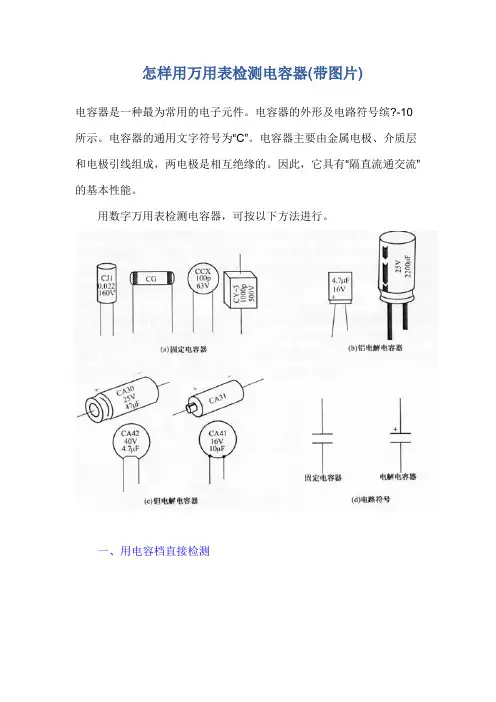
怎样用万用表检测电容器(带图片)电容器是一种最为常用的电子元件。
电容器的外形及电路符号缤?-10所示。
电容器的通用文字符号为“C”。
电容器主要由金属电极、介质层和电极引线组成,两电极是相互绝缘的。
因此,它具有“隔直流通交流”的基本性能。
用数字万用表检测电容器,可按以下方法进行。
一、用电容档直接检测某些数字万用表具有测量电容的功能,其量程分为2000p、20n、200n、2μ和20μ五档。
测量时可将已放电的电容两引脚直接插入表板上的Cx插孔,选取适当的量程后就可读取显示数据。
2000p档,宜于测量小于2000pF的电容;20n档,宜于测量2000pF 至20nF之间的电容;200n档,宜于测量20nF至200nF之间的电容;2μ档,宜于测量200nF至2μF之间的电容;20μ档,宜于测量2μF至20μF之间的电容。
经验证明,有些型号的数字万用表(例如DT890B+)在测量50pF 以下的小容量电容器时误差较大,测量20pF以下电容几乎没有参考价值。
此时可采用串联法测量小值电容。
方法是:先找一只220pF左右的电容,用数字万用表测出其实际容量C1,然后把待测小电容与之并联测出其总容量C2,则两者之差(C1-C2)即是待测小电容的容量。
用此法测量1~20pF的小容量电容很准确。
二、用电阻档检测实践证明,利用数字万用表也可观察电容器的充电过程,这实际上是以离散的数字量反映充电电压的变化情况。
设数字万用表的测量速率为n次/秒,则在观察电容器的充电过程中,每秒钟即可看到n个彼此独立且依次增大的读数。
根据数字万用表的这一显示特点,可以检测电容器的好坏和估测电容量的大小。
下面介绍的是使用数字万用表电阻档检测电容器的方法,对于未设置电容档的仪表很有实用价值。
此方法适用于测量0.1μF~几千微法的大容量电容器。
1.测量操作方法如图5-11(a)所示,将数字万用表拨至合适的电阻档,红表笔和黑表笔分别接触被测电容器Cx的两极,这时显示值将从“000”开始逐渐增加,直至显示溢出符号“1”。
电解电容参数测试方法为规范电解电容参数的测试,增加所测参数的可比性,结合供应商测试标准及实验室测试结果,特制定以下测试标准:一、测试要求1、电容漏电流极值计算公式:CU≤1000µF.V Imax≤0.03CU+15 (µA)CU>1000µF.V Imax≤0.02CU+25 (µA)2、电容测试充电时长:CU≤20000µF.V且U ≤100 T=20sCU>20000µF.V且U ≤100 T=30sU > 100V T=60s3、电容测试频率:高频低阻电容 F=1KHz普通电解电容 F=100Hz4、考虑电容经久未用对漏电流有较大影响,故每个电容在测试前须先充放电10s。
二、漏电流测试仪操作步骤:1、接通电源后,将面板开关按至ON,显示窗口有数字显示,电流窗口显示26,电压窗口显示86,延时1S,电流窗口显示当前漏电流数值,电压窗口显示当前输出电压,仪器预热5分钟进行测试。
2、在放电状态,调整好测量电压、充电时间、最大允许漏电流数值,具体设置方法见面板功能说明。
3、按清0按键,使仪器处于清0状态,仪器电流指示窗口显示为OP-,此时可检查所设置的充电时间及电流极限是否正确,按启动按键,仪器对测试夹具进行开路校正,校正完毕,仪器电流指示窗口显示OPC,按清0按键,使仪器处于测量状态。
4、接上被测电容器:1)、当仪器处于放电状态时,按启动按键或放电按键,使仪器处于充电状态,充电指示灯亮,仪器根据拨盘所设置的充电时间对被测电容进行充电。
2)、当仪器处于测量状态时,在接上被测电容的同时,仪器自动转换为充电状态;充电完成自动转换为测量状态,在电流窗口显示测试数据,如超出量程则显示为---,并判断出合格或不合格(PASS或FAIL)如讯响打开则伴随有蜂鸣器响。
5、测量完毕:1)、统一进行机内放电,按放电按键,放电指示灯亮,放电时间3S以上,放电完成取走被测电容。

电容esr测量标准
电容的等效串联电阻(Equivalent Series Resistance,简称ESR)是电容器内部的电阻,它会影响电容器的性能和稳定性。
测量
电容的ESR是非常重要的,因为它可以帮助我们判断电容器的质量
和健康状况。
一般来说,测量电容的ESR需要使用专门的仪器,例如ESR表(ESR meter)。
ESR表通过施加一个小的交流电压到电容器上,然
后测量电流和电压之间的相位差来计算电容的ESR值。
通常情况下,ESR表会提供一个标准的测试频率,例如100kHz,用于测量电容的ESR。
在测量电容的ESR时,需要注意以下几点标准:
1. 选择合适的测试频率,不同的电容器在不同的频率下会有不
同的ESR值,因此需要根据电容器的类型和规格选择合适的测试频率。
2. 确保电容器处于放电状态,在进行测量之前,需要确保电容
器已经完全放电,以避免电压对测量结果的影响。
3. 测量环境,尽量在稳定的环境下进行测量,避免外部干扰对
测量结果的影响。
此外,还需要根据具体的电容器类型和厂家提供的规格书来确
定合适的ESR测量标准,以确保测量结果的准确性和可靠性。
在实
际操作中,还需要根据ESR表的说明书和操作指南进行正确的操作,以获得准确的测量结果。
总的来说,电容的ESR测量标准需要考虑测试频率、放电状态
和测量环境等因素,并且需要根据具体的电容器类型和规格来确定
合适的测量标准,以确保测量结果的准确性和可靠性。
电容检验标准1、适用范围Applicable Scope本规定适用于单相异步电机运转电容(C B B电容)。
This criterion applies to the running capacitor (CBB) put on the single phase asynchronous motor manufactured by Guangdong Lingxiao Pump Industry Co., ltd.2、执行标准Standard电容器必须符合IEC60252和GB3667有效版本的要求。
Capacitor must comply with the latest version IEC60252&GB3667.3、电容运行等级分级Class of Operation根据IEC60252标准,电容在额定负荷、额定电压、规定温度和额定频率下的最短总寿命分为下列四个等级。
As stipulated in IEC60252, the minimum total life for which the capacitor has been designed at rated duty, voltage, temperature and frequency is:A级(A class)—30000h Class A-30 000hB级(B class)—10000h Class B-10 000hC级(C class)—3000h Class C- 3 000hD级(D class)—1000h Class D- 1 000h4、检验、试验设备Inspection and Testing instruments电容耐久试验综合测试系统、电容冲击测试台、500V直流充击测试台、电容测试仪、20KV A变压器、湿热箱、高压锅等。
The inspection and testing instrument listed as: Capacitorendurance general testing system, capacitor impact testing station, 500V direct current impact testing station,capacitor testing instrument, 20KV A transformer, damp heat testing case, pressure cooker etc.5、检验流程Inspection Procedure5.1.CBB60、CBB61电容检验流程CBB60, CBB61 capacitor inspection procedure:电容整体质量评估外观、标志、认证塑料外壳阻燃性(仅适用于塑料外壳)外型尺寸及引线长度线耳冲压质量或插接端子质量检验电容值和损耗角正切值测量两极间耐压试验极间与外煮水试验冲击试验耐久试验解剖检验、分析出检验报告Capacitor holistic quality evaluation→visual, marks, certification→fire resistance of the plastic shell (only applicable to pla stic shell)→dimension and lead length →termination pressing quality or plug termination quality inspection→measure of capacitor value and tangent of loss angle value→voltage duration test between 2 poles→voltage duration test between pole and shell(only ap plicable to metal shell)→water cooking testimpact test ,duration test →anatomic inspection and analysis→testing report5.2.CBB65电容检验流程CBB65 capacitor inspection procedure:电容整体质量评估外观、标志、认证外型尺寸线耳冲压质量或插接端子质量电容值和损耗角正切值测量两极间耐压试验冲击试验耐久试验解剖检验、分析出检验报告Capacitor holistic quality evaluation→visual, marks, certification→dimension termination pressing quality→measure of capacitor value and tangent of loss angle value voltage duration test between 2 poles→voltage duration test between pole and shell(only app licable to metal shell)→ impact test duration test →anatomic inspection and analysis→testing report6、检验、试验要求Inspection and Testing Requirements6.1.电容试验前整体质量评估Capacitor holistic quality evaluation before test6.1.1.电容器环氧树脂封灌要求(限于CBB60、CBB61电容)Epoxy resin requirements (it is only limited to CBB60, CBB61)6.1.2.电容器的整个芯子都必须有环氧树脂密封,灌封要求按附图1示例。
Capacitance and Dissipation FactorMeasurement ofChip Multilayer Ceramic CapacitorsPage1. Introduction--------------------------------------------------------------12. Characteristics of Chip Multilayer Capacitors-------------------12-1. Temperature Characteristic2-2. Voltage Characteristic(1) AC Voltage Characteristic(2) DC Bias Characteristic2-3. Frequency Characteristic2-4. Summary3. LCR Meters and Measurement Jigs-------------------------------63-1. LCR Meters3-2. Measurement Jigs4. LCR Meter Measurement Principle--------------------------------74-1. Measurement Principle4-2. Measuring Voltage4-3. Capacitance Measurement Circuit Mode5. Capacitance Measurement by LCR Meter 4284A--------------106. Capacitance Measurement by LCR Meter 4278A--------------147. Closing--------------------------------------------------------------------18References------------------------------------------------------------------18Murata Mfg. Co., Ltd.TD No.C10E1. IntroductionWhen you measure a high dielectric MLCC capacitor (X7R-characteristic or Y5V-characteristic) using a LCR meter, there may be a case you can not obtain a reasonable capacitance value within its nominal range.As capacitance and dissipation factor of these Temperature characteristic MLCC capacitors significantly change according to the measurement temperature, voltage (AC, DC) andfrequency. One of the reasons of such a failure to obtain a reasonable capacitance can be that your have not performed the measurement correctly using specified measurement conditions.Another reason may be an incorrect meter setting or use of measurement equipment that does not have the capability needed for accurate measurement.Solutions for the former issue is to fully understand characteristics of MLCC capacitors and the appropriate “three (3) measuring conditions”, i.e. measuring temperature, voltage (AC and DC) and frequency. The actual measurement conditions of capacitance and dissipation factor of high dielectric ceramic capacitors are shown in Table 1 below.The temperature used for these conditions is 25 degree:Table 1 Measuring ConditionsNominal Capacitance Measuring Frequency Measuring VoltageC ≤ 10µF (10V or greater) 1 ± 0.1kHz 1.0 ± 0.2VrmsC ≤ 10µF (6.3V or less) 1 ± 0.1kHz0.5 ± 0.1VrmsC > 10µF120 ± 24Hz0.5 ± 0.1VrmsThe solution for the second issue is to understand the capability of the measurement equipment to be used and to confirm that it meets the measurement conditions listed in Table 1.In this brochure, we will first describe the characteristics of the MLCC capacitors that can affect capacitance and dissipation factor measurement. Next, the measuring principle of the LCR meters used for actual measurement is described, then an example of the correct method used to measure the capacitance and dissipation factor of the MLCC capacitors is explained.2. Characteristics of the MLCC (Multilayer Ceramic Chip) CapacitorsThe MLCC capacitors have excellent features such as small size, high reliability, lowimpedance and no-polarity, etc., but on the other hand, they have demerits such as capacitance change with temperature or voltage change.In the following sections, measurements of 1206 type 10µF X7R-characteristic and Y5V-characteristic MLCC capacitors are taken up as examples to explain the various characteristics that can affect the measurement of capacitance and dissipation factor.2-1. Temperature CharacteristicTemperature characteristics of MLCC capacitors are shown in Fig.1 below:At the measurement conditions of 1kHz, 1Vrms, whereas capacitance change ratio of the X7R-characteristic is within ± 10% at maximum, The Y5V-characteristic capacitor is allowed to over a wider range of + 30% / -80%. Dissipation factor also changes according to measurement temperature, which tends to go up in lower temperatures for both X7R- and Y5V- characteristic capacitors.(a) Capacitance Change Ratio(b) Dissipation Factor (DF)Fig.1 Temperature Characteristic(1) AC Voltage CharacteristicThe AC voltage characteristics of X7R- and Y5V-characteristic MLCC capacitors are shown in Fig.2 below:At the measurement conditions of 25 degree, 1kHz, while capacitance change ratio of the X7R-characteristic capacitors is within ± 5% at maximum, the capacitance of Y5V-characteristic capacitors drops by 50% at the maximum and changes according to applied AC voltage level.Although the dissipation factor of Y5V-characteristic capacitor also changes significantlyaccording to the measurement voltage, the X7R-characteristic capacitor shows very little change.(a) Capacitance Change Ratio(b) Dissipation Factor (DF)Fig.2 AC Voltage CharacteristicThe DC bias characteristics of X7R- and Y5V-characteristic MLCC capacitors are shown in Fig.3 below:At the measurement conditions of 25 degree, 1kHz, 1vrms, the capacitance of the X7R-characteristic capacitor drops by a maximum of 60% according to DC bias voltage applied, while the capacitance of the Y5V-characteristic capacitor drops as much as 90%.The capacitance of MLCC capacitors decreases as applied DC bias voltage increases. Also dissipation factors of those capacitors comes down as DC bias voltage goes up.(a) Capacitance Change Ratio(b) Dissipation Factor (DF)Fig.3 DC Bias Characteristic2-3. Frequency CharacteristicThe frequency characteristics of X7R- and Y5V-characteristic MLCC capacitors are shown in Fig.3 below:Although capacitance of both X7R- and Y5V-characteristic capacitors changes little as the measurement frequency is altered, their dissipation factors change substantially according to the measurement frequency. The reason the Y5V-characteristic capacitor’s capacitance drops lower than 50% is that generally it is not possible to apply 1Vrms with the usual impedance analyzer(e.g. LCR meter) to the Y5V -characteristic capacitor at these (shown) frequency steps and0.1Vrms is used instead. At the AC measurement voltage of 0.1Vrms, the capacitance of Y5V-characteristics decreases by 50% as shown in Fig.2 (AC Voltage Characteristic.)(a) Capacitance Change Ratio(b) Dissipation Factor (DF)Fig.4 Frequency Characteristic2-4. SummaryAs described above, the capacitance and dissipation factors of MLCC capacitors change according to the measurement temperature, AC voltage, DC bias and frequency. Therefore, the capacitance and dissipation factor of these capacitors shall be measured after specifying the three measurement conditions, “temperature”, “voltage (AC & DC)” and “frequency”. When you design an electronic circuit using these capacitors, use them after carefully considering their characteristic values at the intended environment and operating conditions.3. LCR Meters and Measuring JigsTypical LCR meters and measurement jigs are introduced in this section.3-1. LCR MetersLCR meters are generally used for measurement of the capacitance and dissipation factor of capacitors. Typical LCR meters include 4284A, 4278A and 4268A by Agilent Technologies Corp.as shown in Fig.5. As there are some measurement instruments that do not meet themeasurement conditions specified in Table 1, please review the measurement principles in Section 4 and measurement methods in Section 5 and 6 before performing any tests.(a) 4284A(b) 4278A(c) 4268AFig.5 Exterior Photographs of LCR Meters3-2. Measuring JigsIt is necessary to select a measurement jig appropriate the LCR meter to be used. Typical measurement jigs used for MLCC capacitors are shown in Fig.6 below:(a) 16034E (b) 16334AFig.6 Appearance Photographs of Measuring JigsThere are two types of measurement jigs, a type on which a chip capacitor is placed and measured by applying a pin to one-side of the electrode terminal, such as 16034E of Agilent Technologies Corp. and another type that is shaped like tweezers to catch a chip capacitor by its terminals to measure it such as 16334A also from Agilent Technologies Corp.4. LCR Meter Measurement PrincipleThe basic issues necessary for LCR capacitor measurement such as the LCR metermeasurement principle and measuring voltage, etc. are explained in this section.4-1. Measurement PrincipleThe typical “measurement system” of LCR meters is the “automatic balancing bridge method”, which is shown in Fig.7.In Fig.7, a high gain amplifier automatically adjusts the gain level so that an eclectic current is drawn through a resistor. R is always equal to the current flowing through the DUT (Device under Test), that is, the L-side end potential of DUT (lower voltage side) always equal to virtual ground level (electric potential =0). At this condition, impedance value of the DUT can be determined from the out put voltage E2, feedback resistance R and input voltage E1 as follows:Zx=R∗E1/E2E1= |E1| ∠θ1 = |E1|cosθ1+|E1|sinθ1E2= |E2| ∠θ2 = |E2|cosθ2+|E2|sinθ2At this moment, phase angles of E1 and E2, θ1 and θ2, are measured at the same time, and the “resistance component Rx” and “reactance component Xx” can be calculated from the above phase angles and Zx value, from which capacitance and dissipation factor are determined.High gain amplifierFig.7 Principle Diagram of Automatic Balancing Bridge4-2. Measuring VoltageLCR meters generally provide internal resistances to protect their own power supply circuits.Depending on the value of this resistance, the actual voltage differential between the electrodes of a capacitor being measured drops excessively which prevents correct measurement of capacitance and dissipation factor of the capacitor. Depending on type of LCR meter used,measurement of a ceramic capacitor with large capacitance such as 10µF at an assigned voltage may be impossible due to extremely low impedance of such capacitor.This mechanism is explained using the simple equivalent circuit model shown in Fig.8.Measuring voltage is applied to DUT, E dut is a partial potential of power supply voltage E O divided by impedance of DUT, Zx = R + jX, and the LCR meter’s internal impedance R in .The measuring voltage applied to DUT, E dut , is determined by: √(R 2+X 2)E dut =E0∗√{(Rin+R)2+X 2}X=1/ωC=1/(2πfC)Thus, the measurement voltage of capacitor is different from the power supply voltage.Therefore, we recommend using a LCR meter that automatically maintains the “measurement voltage” at a preset voltage (ALC function). When using a LCR meter not providing such function,you have to manually measure actual voltage applied between the terminals of the capacitor being measured, etc. and manually adjust it.Fig.8 Measuring Voltage Applied to DUT4-3. Capacitance Measurement Circuit ModeCapacitance measurement circuit mode generally includes two types of circuit modes.These are; parallel equivalent circuit mode and serial equivalent circuit mode.(1) In case of small capacitance (see Fig.9):A small capacitance has a large reactance, i.e. high impedance, which causes the influence of parallel resistance Rp on the measurement to be far larger than that of the serial resistance Rs, thus Rs can be neglected and measurement circuit provides a parallel equivalent circuit mode.(2) In case of large capacitance (see Fig.10):Internal resistancePowersupplyA large capacitance has a small reactance, i.e. low impedance, which makes the influenceof serial resistance Rs on the measurement far larger than that of parallel capacitance Rp, thus Rp can be neglected and measurement circuit provides a serial equivalent circuit mode.High impedance)Low impedance)Fig.9 Small capacitance Eig.10 Large capacitance(Parallel equivalent circuit mode) (Serial equivalent circuit mode)(3) The measurement circuit mode is determined according to impedance value of a capacitor tobe measured, which is switched at about 10Ω in relation to internal impedance of LCR meter.The relationship between capacitance and impedance is shown in Fig.11. The “Electric Capacitance” (4.7) and “Dielectric Dissipation Factor” (4.8) sections of the public standard JIS C 5101-1-1998 define measurement frequency to 1kHz for 10µF or lower capacitance and to 120Hz for capacitance higher than 10µF. Therefore, the impedances of all these capacitance values become 10Ω or greater, which are measured by the parallel equivalent circuit mode. However, for a capacitance exceeding 10µF, the serial equivalent circuit mode is used, as its impedance is lower than 10µF.][Fig.11 Relation between Capacitance and Impedance5. Capacitance Measurement by LCR Meter 4284AThe correct capacitance measurement method using a typical LCR meter 4284A andmeasurement jig 16034E is described in this section.5-1. Turn on the power of LCR meterThis measurement equipment requires warm-up time. Turn the power on for the meter 30 minutes before starting actual measurement.5-2. Installing the measuring jig on the meterInstall the measurement jig on the meter as shown in Fig.12.5-3. Setting the LCR meterSetup measurement conditions using “Measure Setup” screen (see Fig.13).(1) FUNC Æ Cp-D,(2) FREQ and LEVELÆ See Table 1.Fig.12 LCR Meter with Jig InstalledFig.13 Measure Setup ScreenNote 1: If FREQ and/or LEVEL is not correctly set, you will not be able to correctly measure the capacitance. These settings are explained in the followingexample:Example: Sample capacitor 1812 type X5R-characteristic 100µFCorrect settings for the frequency and AC voltage are “FREQ: 120Hz” and “LEVEL: 0.5Vrms”respectively (see Fig.14). If capacitance is measured using different conditions, such as1kHz and 1Vrms, the capacitance will be incorrectly displayed, as being 20% lower than if measured using the correct conditions as shown in Fig.15.ABC“A” field in the above figure is set to measurement frequency and voltage required. This field is correctly set to “FREQ: 120Hz” and “LEVEL: 500mV” according to the specification. “B” is a field that displays the values of measured capacitance and dissipation factor. The capacitance is about 94µF is compared against the nominal value of 100µF of the sample capacitor, this is within the specified capacitance tolerance. “Vm” in “C”field indicates actual the measurement voltage monitored by the meter, which shows 500mV applied to the sample.Fig.14 Measuring Conditions : 120Hz, 0.5VrmsABC“A” field in the above figure is set to “FREQ: 1kHz” and “LEVEL: 1V”, both of which are different from sample’s specification. The capacitance indicated in “B” field above is very low, about 75µF against nominal value of 100µF of the sample capacitor, which is 20% lower than that measured by the correct conditions.“Vm” in “C” field indicates the actual measurement voltage monitored by the meter, which shows only about 21mv against set value 1V.Fig.15 Measurement Conditions : 1kHz, 1Vrms(3) Hi-PW (High Power) Æ ON, and ALC (Automatic Level Control) Æ ONWhen “Hi-PW” is set to “ON”, the capacitance can be measured with the Power Supply voltage within set to a range of 1Vrms to 10Vrms. ALC is used to maintain the measurement voltage at the designated voltage and shall be always set to “ON”. Even if you set the measurement voltage to 1Vrms, you cannot obtain the correct capacitance value unless the actually monitored value is 1Vrms. This setting is explained using the following example: Example : Sample 1206 type X7R-characteristic 10µFBy setting the ALC and Hi-PW to “ON”, you can apply 1Vrms measurement voltage to a sample to be measured, and obtain a correct capacitance value, which is about 9.86µF in the example (see Fig.16 and 17). When ALC is set to “OFF”, measurement voltage becomes low 184mV in the example figure below, which makes apparent capacitance low, showing about 8.43µF.AB”A” field in the above figure indicates both ALC and Hi-PW being set to “ON”.An asterisk mark at “B” field in the figure means ALC being on.Fig.16 Measure Setup Screen Showing ALC ONBA“Vm” in “A” field in the above figure indicates actual measurement voltage monitored by the meter, which shows 1V being applied to the sample. “B” field shows the capacitance of a 10µF product, which is about 9.86µF which is within the specified tolerance.Fig.17 Measure Setup Screen Showing ALC ONBA“A” field in the above figure indicates ALC being set to “OFF” and Hi-PW being set to “ON”. No asterisk mark at “B” field in the figure means ALC is off.Fig.18 Measure Setup Screen Showing ALC OFFBA“Vm” in “A” field indicates actual measurement voltage monitored by the meter, which shows 1V is applied to the sample. “B” field shows a capacitance of a 10µF product, which is about 9.86µF which is within the specified tolerance.Fig.19 Measure Setup Screen Showing ALC OFFNote 2: Check Method of Measurement Voltage Applied to Capacitor Under Test One method to check the measurement voltage actually applied to a capacitor under test is to apply plus and minus probes of the tester to both terminals respectively of the capacitor set into measurement jig, and read the indicated voltage.A photograph in which “measurement voltage” of Fig.17 above is checked is shown in Fig.10. It shows it indicates a value of 998mVrms.Also, a photograph in which the “measurement voltage” of Fig.19 is checked is shown in Fig.21. It shows the tester indicating 187mVrms and low capacitance due to the AC measurement voltage being less than 1Vrms.TesterFig.20 Tester Measurement Example for ALC ON StateTesteFig.21 Tester Measurement Example for ALC OFF State5-4. CalibrationYou implement the measurement calibration using COMPEN in the MEAS SETUP screen.The are two types of calibration “Short Calibration” and “Open Calibration”,The order in which you preform the calibration is optional.(1) Short CalibrationFor “short” condition, see Fig.22. Confirm that Rs is 0.03 Ω or less at this point. When Rs does not come down to 0.03 Ω or less, then wash the terminal using acetone, repeat above as necessary to obtain a Rs reading of 0.03 Ω or less.(a) 16034E (b) 16334AFig.22 Short Condition(2) Open CalibrationAdjust “open” distance to a size of chip capacitor to be measured. See Fig.23 for “open”condition.(a) 16034E (b) 16334AFig.23 Open Condition5-5. MeasurementYou measure the MLCC capacitors after completing these calibrations.6. Capacitance Measurement by LCR Meter 4278AIn this section, A correct capacitance measurement method using the combination of a typical LCR meter 4278A and measuring jig 1603A is explained.6-1. Turn on LCR Meter PowerThe equipment requires a warming-up time, always turn on its power 30 minutes before starting your actual measurement.6-2. Meter with Measuring Jig installed onInstall the measuring jig on the measuring equipment as shown in Fig.24.Fig.24 Meter with Measuring Jig installed on6-3. Meter SettingSet measurement conditions on the meter using ”Menu” screen shown in Fig.25.(1) Setting items to be measured:MENU ÆMEAS, PARAMETER Æ Cp-D(2) Setting measuring frequency and voltage :MENU Æ SIGMAL, SOURCE Æ FREQ Æ 1kHzÆ OSC Æ 1.0VNote 4: 4278A provides two types frequencies, 1kHz and 1MHz. Therefore, it cannot measure a capacitor having a capacitance greater than 10µFbecause such capacitance requires a measurement frequency of 120Hz.Use 4284A or 4268A for the measurement of a capacitor greater than 10µF.Fig.25 Menu ScreenNote 5: Check Method of Measurement Voltage Actually Applied to a Capacitor Even though you set the measurement voltage to 1Vrms, if “1Vrms” is not actuallyapplied to the capacitor to be measured, you won’t be able to correctly measurecapacitance.Check whether the measurement voltage set is actually applied to the capacitor byapplying plus and minus probes of a tester to both terminals of the capacitor set inmeasuring jig and read a indicated voltage.Fig.26 shows the check operation of the measurement voltage of a 1206 size X7R-characteristic 10µF chip capacitor, in which measurement frequency is set to 1kHZ and measurement voltage to 1Vrms. Actual measurement voltage is about 1.0Vrms andmeasured capacitance is about 10.4µF.Fig.26 Measurement Voltage Check by Tester(3) Cable LengthWhen using measurement jig 16034E, set CABLE LENGTH to “0 (zero)”m.MENU Æ NEXT Æ CABLE LENGTH Æ 0m.6-4. CalibrationUse “screen” displayed after pushing MENU Æ NEXT Æ COMPEN for the calibration.The calibration at this point shall be performed for OPEN, SHORT and TEMP COMP. See LCR meter 4284 measurement procedure in Section 5 herein for OPEN and SHORTcalibration methods.OPEN COMPEN Æ OPEN ONSHOT COMPEN Æ SHORT ONSTD OFFTEMP COMPEN6-5. MeasurementYou can start the measurement of the MLCC capacitors after completing the TEMPCOMPEN above.Note 6: Capacitance Change by Aging CharacteristicAlthough the “aging characteristic” of high dielectric MLCC capacitors is not directly related to the capacitance measurement, as it reduces capacitance of the MLCCcapacitors, you must take it into consideration when designing a circuit using thosecapacitors.High dielectric MLCC capacitors (typically represented by X7R / Y5V temperature characteristic of which main composition is BaTiO3) have an attribute that theircapacitance decreases as time elapses. This attribute is called “aging” of capacitance.Capacitance aging is a phenomenon inherent in dielectric ceramics havingspontaneous polarization. When a ceramic capacitor of this type is heated up over its Curie point and left at a temperature lower that the Curie point with no load, the rotation of its spontaneous polarization is gradually inactivated as time elapses, which is observed from outside as “capacitance decrease”.This phenomenon is not limited to our products but generally observed in all highdielectric MLCC capacitors (with BaTiO3 system). Some public standards have anappendix for supplemental explanation about the aging of electric capacitance (Multilayer Capacitor: IEC 384-10 Appendix X7R, etc.) If a MLCC capacitor with aging-reduced low capacitance is again heated up over its Curie point, its capacitance is restored to nominal again the aging process from the time point it is cooled down to a temperature lower than the Curie point starts again.Generally, using a capacitance value reading 24 hours after heat-treatment at 150 degree or higher as a baseline, the capacitance linearly decreases according to logarithm time scale.See a typical example of a capacitance aging characteristic graph decreasing with time shown in Fig.27.Fig. 27 Aging Characteristic, Capacitance Change with TimeWhen you use high dielectric MLCC capacitors, please carefully consider thecapacitance change of these capacitors arising from their aging characteristics, and particularly when you need a stable capacitance, check capacitors using your actual appliances. However, temperature compensating type MLCC capacitors have no such aging characteristic.7. ClosingIn order to correctly measure MLCC capacitors, it is necessary to fully understand theproduct characteristics that affect the measurement of those capacitors and using LCR meter performances.This brochure explains key points in the measurement that are likely to be mistaken or overlooked. We hope that this brochure is useful for your capacitor measurement.References•4284A Operation Manual, Agilent Technologies Corp.•4278A,Operation Manual, Agilent Technologies Corp.•Impedance Measurement Handbook, Agilent Technologies Corp. Second Edition, 2001•Basics and Applications of Ceramic Capacitor, Ohmsha, First Edition, 2003Document Prepared: September 2005。