
stm32蜂鸣器实验代码
- 格式:doc
- 大小:25.50 KB
- 文档页数:1


实验1 GPIO#include "stm32f10x.h"#include "delay.h"//#include "sys.h"#include "stm32f10x_exti.h"//QHKJ TEB-CM5000实验箱STM32实验1//固件库V3.5工程模板//QHKJGPIO_InitTypeDef GPIO_InitStructure;EXTI_InitTypeDef EXTI_InitStructure;/* Private function prototypes -----------------------------------------------*/ void RCC_Configuration(void);void NVIC_Configuration(void);void GPIO_Configuration(void);/* Private functions ---------------------------------------------------------*//******************************************************************************** Function Name : main* Description : Main program.* Input : None* Output : None* Return : None*******************************************************************************/int main(void){/* Configure the system clocks */// RCC_Configuration();// SysTick_Configuration();delay_init();/* NVIC Configuration */NVIC_Configuration();/* Configure the GPIO ports */GPIO_Configuration();/* Connect EXTI Line9 to PA.9 */GPIO_EXTILineConfig(GPIO_PortSourceGPIOA, GPIO_PinSource9);/* Configure EXTI Line8 to generate an interrupt on falling edge */EXTI_InitStructure.EXTI_Line = EXTI_Line9;EXTI_InitStructure.EXTI_Mode = EXTI_Mode_Interrupt;EXTI_InitStructure.EXTI_Trigger = EXTI_Trigger_Falling;EXTI_InitStructure.EXTI_LineCmd = ENABLE;EXTI_Init(&EXTI_InitStructure);for(;;){GPIO_Write(GPIOF, 0xf80f);delay_ms(100);GPIO_Write(GPIOF, 0xf817);delay_ms(100);GPIO_Write(GPIOF, 0xf827);delay_ms(100);GPIO_Write(GPIOF, 0xf847);delay_ms(100);GPIO_Write(GPIOF, 0xf887);delay_ms(100);GPIO_Write(GPIOF, 0x8907);delay_ms(100);GPIO_Write(GPIOF, 0xfa07);delay_ms(100);GPIO_Write(GPIOF, 0xfc07);delay_ms(100);}}/******************************************************************************* * Function Name : NVIC_Configuration* Description : Configures Vector Table base location.* Input : None* Output : None* Return : None*******************************************************************************/ void NVIC_Configuration(void){NVIC_InitTypeDef NVIC_InitStructure;/* Configure one bit for preemption priority */NVIC_PriorityGroupConfig(NVIC_PriorityGroup_1);/* Enable the EXTI9_5 Interrupt */// NVIC_InitStructure.NVIC_IRQChannel = EXTI9_5_IRQChannel;NVIC_InitStructure.NVIC_IRQChannel = EXTI9_5_IRQn;NVIC_InitStructure.NVIC_IRQChannelPreemptionPriority = 0;NVIC_InitStructure.NVIC_IRQChannelSubPriority = 0;NVIC_InitStructure.NVIC_IRQChannelCmd = ENABLE;NVIC_Init(&NVIC_InitStructure);}/******************************************************************************** Function Name : GPIO_Configuration* Description : Configures the different GPIO ports.* Input : None* Output : None* Return : None*******************************************************************************/void GPIO_Configuration(void){GPIO_InitTypeDef GPIO_InitStructure;/* Enable GPIOA, GPIOF and AFIO clocks */RCC_APB2PeriphClockCmd(RCC_APB2Periph_GPIOA | RCC_APB2Periph_GPIOF |RCC_APB2Periph_AFIO, ENABLE);/* Configure PF. as Output push-pull */GPIO_InitStructure.GPIO_Pin = GPIO_Pin_3|GPIO_Pin_4|GPIO_Pin_5|GPIO_Pin_6|GPIO_Pin_7|GPIO_Pin_8|GPIO_Pin_9|GPIO_Pi n_10;GPIO_InitStructure.GPIO_Speed = GPIO_Speed_50MHz;GPIO_InitStructure.GPIO_Mode = GPIO_Mode_Out_PP;GPIO_Init(GPIOF, &GPIO_InitStructure);/* Configure PA9 as input floating (EXTI Line9) */GPIO_InitStructure.GPIO_Pin = GPIO_Pin_9;// GPIO_InitStructure.GPIO_Mode = GPIO_Mode_IN_FLOATING;GPIO_InitStructure.GPIO_Mode = GPIO_Mode_IPU;GPIO_Init(GPIOA, &GPIO_InitStructure);}实验7 LED流水灯#include "stm32f10x.h"//QHKJ TEB-CM5000实验箱STM32实验7//固件库V3.5工程模板//QHKJ/*LED灯相关定义*/#define RCC_GPIO_LED RCC_APB2Periph_GPIOF /*LED使用的GPIO时钟*/#define LEDn 8 /*LED数量*/#define GPIO_LED GPIOF /*LED灯使用的GPIO组*/#define LD1_PIN GPIO_Pin_3 /*LD1使用的GPIO 管脚*/#define LD2_PIN GPIO_Pin_4 /*LD2使用的GPIO管脚*/#define LD3_PIN GPIO_Pin_5 /*LD3使用的GPIO管脚*/#define LD4_PIN GPIO_Pin_6 /*LD4使用的GPIO管脚*/#define LD5_PIN GPIO_Pin_7 /*LD5使用的GPIO 管脚*/#define LD6_PIN GPIO_Pin_8 /*LD6使用的GPIO管脚*/#define LD7_PIN GPIO_Pin_9 /*LD7使用的GPIO管脚*/#define LD8_PIN GPIO_Pin_10 /*LD8使用的GPIO管脚*//* Private macro -------------------------------------------------------------*//* Private variables ---------------------------------------------------------*/ GPIO_InitTypeDef GPIO_InitStructure;u8 count=0;/* Private function prototypes -----------------------------------------------*///void RCC_Configuration(void);//void NVIC_Configuration(void);void Delay(vu32 nCount);void Turn_On_LED(u8 LED_NUM);/* Private functions ---------------------------------------------------------*//******************************************************************************** Function Name : main* Description : Main program.* Input : None* Output : None* Return : None*******************************************************************************/int main(void){/* 配置LED灯使用的GPIO管脚模式*/RCC_APB2PeriphClockCmd(RCC_GPIO_LED, ENABLE); /*使能LED灯使用的GPIO时钟*/GPIO_InitStructure.GPIO_Pin = LD1_PIN|LD2_PIN|LD3_PIN|LD4_PIN|LD5_PIN|LD6_PIN|LD7_PIN|LD8_PIN;GPIO_InitStructure.GPIO_Mode = GPIO_Mode_Out_PP;GPIO_InitStructure.GPIO_Speed = GPIO_Speed_50MHz;GPIO_Init(GPIO_LED, &GPIO_InitStructure); /*使用的LED灯相关的GPIO口初始化*/GPIO_ResetBits(GPIO_LED,LD1_PIN|LD2_PIN|LD3_PIN|LD4_PIN|LD5_PIN|LD6_PIN|LD7_PI N|LD8_PIN);/*关闭所有的LED指示灯*/while(1){GPIO_ResetBits(GPIO_LED,LD1_PIN|LD2_PIN|LD3_PIN|LD4_PIN|LD5_PIN|LD6_PIN|LD7_PI N|LD8_PIN);/*关闭所有的LED指示灯*/Turn_On_LED(count%8); //点亮一个LED灯count++;Delay(0x0FFFFF);}}/*点亮对应灯*/void Turn_On_LED(u8 LED_NUM){switch(LED_NUM){case 0:GPIO_SetBits(GPIO_LED,LD1_PIN); /*点亮LD1灯*/break;case 1:GPIO_SetBits(GPIO_LED,LD2_PIN); /*点亮LD2灯*/break;case 2:GPIO_SetBits(GPIO_LED,LD3_PIN); /*点亮LD3灯*/break;case 3:GPIO_SetBits(GPIO_LED,LD4_PIN); /*点亮LD4灯*/break;case 4:GPIO_SetBits(GPIO_LED,LD5_PIN); /*点亮LD5灯*/break;case 5:GPIO_SetBits(GPIO_LED,LD6_PIN); /*点亮LD6灯*/break;case 6:GPIO_SetBits(GPIO_LED,LD7_PIN); /*点亮LD7灯*/break;case 7:GPIO_SetBits(GPIO_LED,LD8_PIN); /*点亮LD8灯*/break;default:GPIO_SetBits(GPIO_LED,LD1_PIN|LD2_PIN|LD3_PIN|LD4_PIN|LD5_PIN|LD6_PIN|LD7_PIN|LD8_ PIN); /*点亮所有的灯*/break;}}/******************************************************************************** Function Name : Delay* Description : Inserts a delay time.* Input : nCount: specifies the delay time length.* Output : None* Return : None*******************************************************************************/void Delay(vu32 nCount){for(; nCount != 0; nCount--);}实验11 串口收发#include "stm32f10x.h"#include "stm32f10x_usart.h"//QHKJ TEB-CM5000实验箱STM32实验11//固件库V3.5工程模板//QHKJ/* Private typedef -----------------------------------------------------------*//*LED灯相关定义*/#define RCC_GPIO_LED RCC_APB2Periph_GPIOF /*LED使用的GPIO时钟*/#define LEDn 4 /*LED数量*/#define GPIO_LED GPIOF /*LED灯使用的GPIO组*/#define LD1_PIN GPIO_Pin_3 /*LD1使用的GPIO 管脚*/#define LD2_PIN GPIO_Pin_4 /*LD2使用的GPIO管脚*/#define LD3_PIN GPIO_Pin_5 /*LD3使用的GPIO管脚*/#define LD4_PIN GPIO_Pin_6 /*LD4使用的GPIO管脚*//*串口相关定义*/#define USART1_GPIO GPIOA#define USART1_CLK RCC_APB2Periph_USART1#define USART1_GPIO_CLK RCC_APB2Periph_GPIOA#define USART1_RxPin GPIO_Pin_10#define USART1_TxPin GPIO_Pin_9//#define USART1_IRQn USART1_IRQn//#define USART1_IRQHandler USART1_IRQHandler#define USART2_GPIO GPIOA#define USART2_CLK RCC_APB1Periph_USART2#define USART2_GPIO_CLK RCC_APB2Periph_GPIOA#define USART2_RxPin GPIO_Pin_3#define USART2_TxPin GPIO_Pin_2//#define USART2_IRQn USART2_IRQn//#define USART2_IRQHandler USART2_IRQHandlerGPIO_InitTypeDef GPIO_InitStructure;/* Private typedef -----------------------------------------------------------*/ typedef enum { FAILED = 0, PASSED = !FAILED} TestStatus;/* Private define ------------------------------------------------------------*/#define TxBufferSize1 (countof(TxBuffer1) - 1)#define TxBufferSize2 (countof(TxBuffer2) - 1)#define RxBufferSize1 TxBufferSize2#define RxBufferSize2 TxBufferSize1/* Private macro -------------------------------------------------------------*/ #define countof(a) (sizeof(a) / sizeof(*(a)))/* Private variables ---------------------------------------------------------*/ USART_InitTypeDef USART_InitStructure;u8 TxBuffer1[] = "串口中断收发示例: 串口1 -> 串口2 (中断收发)";u8 TxBuffer2[] = "串口中断收发示例: 串口2 -> 串口1 (中断收发)";u8 RxBuffer1[RxBufferSize1];u8 RxBuffer2[RxBufferSize2];u8 TxCounter1 = 0x00;u8 TxCounter2 = 0x00;u8 RxCounter1 = 0x00;u8 RxCounter2 = 0x00;u8 NbrOfDataToTransfer1 = TxBufferSize1;u8 NbrOfDataToTransfer2 = TxBufferSize2;u8 NbrOfDataToRead1 = RxBufferSize1;u8 NbrOfDataToRead2 = RxBufferSize2;u8 TransferStatus1 = FAILED;u8 TransferStatus2 = FAILED;/* Private function prototypes -----------------------------------------------*/ void RCC_Configuration(void);void GPIO_Configuration(void);void NVIC_Configuration(void);TestStatus Buffercmp(u8* pBuffer1, u8* pBuffer2, u16 BufferLength);/* Private functions ---------------------------------------------------------*//*** @brief Main program* @param None* @retval None*/int main(void){/* System Clocks Configuration */RCC_Configuration();/* NVIC configuration */NVIC_Configuration();/* Configure the GPIO ports */GPIO_Configuration();GPIO_ResetBits(GPIO_LED,LD1_PIN|LD2_PIN|LD3_PIN|LD4_PIN);/*关闭所有的LED指示灯*/ /* USART1 and USART2 configuration ------------------------------------------------------*//* USART1 and USART2 configured as follow:- BaudRate = 9600 baud- Word Length = 8 Bits- One Stop Bit- No parity- Hardware flow control disabled (RTS and CTS signals)- Receive and transmit enabled*/USART_ART_BaudRate = 115200; /*设置波特率为115200*/USART_ART_WordLength = USART_WordLength_8b;/*设置数据位为8*/ USART_ART_StopBits = USART_StopBits_1; /*设置停止位为1位*/ USART_ART_Parity = USART_Parity_No; /*无奇偶校验*/USART_ART_HardwareFlowControl = USART_HardwareFlowControl_None;/*无硬件流控*/USART_ART_Mode = USART_Mode_Rx | USART_Mode_Tx; /*发送和接收*//*配置串口1 */USART_Init(USART1, &USART_InitStructure);/*配置串口2*/USART_Init(USART2, &USART_InitStructure);/*使能串口1的发送和接收中断*/USART_ITConfig(USART1, USART_IT_RXNE, ENABLE);USART_ITConfig(USART1, USART_IT_TXE, ENABLE);/*使能串口2的发送和接收中断*/USART_ITConfig(USART2, USART_IT_RXNE, ENABLE);USART_ITConfig(USART2, USART_IT_TXE, ENABLE);/* 使能串口1 */USART_Cmd(USART1, ENABLE);/* 使能串口2 */USART_Cmd(USART2, ENABLE);/* Wait until end of transmission from USART1 to USART2 */while(RxCounter2 < RxBufferSize2){}/* Wait until end of transmission from USART2 to USART1 */while(RxCounter1 < RxBufferSize1){}/* Check the received data with the send ones */TransferStatus1 = Buffercmp(TxBuffer2, RxBuffer1, RxBufferSize1);/* TransferStatus1 = PASSED, if the data transmitted from USART2 andreceived by USART1 are the same *//* TransferStatus1 = FAILED, if the data transmitted from USART2 andreceived by USART1 are different */TransferStatus2 = Buffercmp(TxBuffer1, RxBuffer2, RxBufferSize2);/* TransferStatus2 = PASSED, if the data transmitted from USART1 andreceived by USART2 are the same *//* TransferStatus2 = FAILED, if the data transmitted from USART1 andreceived by USART2 are different */while (1){if(TransferStatus1 == PASSED){GPIO_SetBits(GPIO_LED,LD1_PIN);/*点亮LD1,串口1接收的数据与串口2发送的数据相同*/}else if(TransferStatus1 == FAILED){GPIO_SetBits(GPIO_LED,LD2_PIN);/*点亮LD2,串口1接收的数据与串口2发送的数据不相同*/}if(TransferStatus2 == PASSED){GPIO_SetBits(GPIO_LED,LD3_PIN);/*点亮LD3,串口2接收的数据与串口1发送的数据相同*/}else if(TransferStatus2 == FAILED){GPIO_SetBits(GPIO_LED,LD4_PIN);/*点亮LD4,串口2接收的数据与串口1发送的数据不相同*/}}}/*** @brief Configures the different system clocks.* @param None* @retval None*/void RCC_Configuration(void){/*使能串口1和串口2使用的GPIO时钟*/RCC_APB2PeriphClockCmd(USART1_GPIO_CLK |USART2_GPIO_CLK, ENABLE); /* Enable USART1 Clock *//*使能串口1时钟*/RCC_APB2PeriphClockCmd(USART1_CLK, ENABLE);/*使能串口2时钟*/RCC_APB1PeriphClockCmd(USART2_CLK, ENABLE);/*使能LED灯使用的GPIO时钟*/RCC_APB2PeriphClockCmd(RCC_GPIO_LED, ENABLE);}/*** @brief Configures the different GPIO ports.* @param None* @retval None*/void GPIO_Configuration(void){GPIO_InitTypeDef GPIO_InitStructure;/*串口1 RX管脚配置*//* Configure USART1 Rx as input floating */GPIO_InitStructure.GPIO_Pin = USART1_RxPin;GPIO_InitStructure.GPIO_Mode = GPIO_Mode_IN_FLOATING;GPIO_Init(USART1_GPIO, &GPIO_InitStructure);/*串口2 RX管脚配置*//* Configure USART2 Rx as input floating */GPIO_InitStructure.GPIO_Pin = USART2_RxPin;GPIO_Init(USART2_GPIO, &GPIO_InitStructure);/*串口1 TX管脚配置*//* Configure USART1 Tx as alternate function push-pull */GPIO_InitStructure.GPIO_Pin = USART1_TxPin;GPIO_InitStructure.GPIO_Speed = GPIO_Speed_50MHz;GPIO_InitStructure.GPIO_Mode = GPIO_Mode_AF_PP;GPIO_Init(USART1_GPIO, &GPIO_InitStructure);/*串口2 TX管脚配置*//* Configure USART2 Tx as alternate function push-pull */GPIO_InitStructure.GPIO_Pin = USART2_TxPin;GPIO_Init(USART2_GPIO, &GPIO_InitStructure);/* 配置LED灯使用的GPIO管脚模式*/GPIO_InitStructure.GPIO_Pin = LD1_PIN|LD2_PIN|LD3_PIN|LD4_PIN; GPIO_InitStructure.GPIO_Mode = GPIO_Mode_Out_PP;GPIO_InitStructure.GPIO_Speed = GPIO_Speed_50MHz;GPIO_Init(GPIO_LED, &GPIO_InitStructure);}/*** @brief Configures the nested vectored interrupt controller.* @param None* @retval None*/void NVIC_Configuration(void){NVIC_InitTypeDef NVIC_InitStructure;/* Configure the NVIC Preemption Priority Bits */NVIC_PriorityGroupConfig(NVIC_PriorityGroup_0);/* Enable the USART1 Interrupt */NVIC_InitStructure.NVIC_IRQChannel = USART1_IRQn;NVIC_InitStructure.NVIC_IRQChannelSubPriority = 0;NVIC_InitStructure.NVIC_IRQChannelCmd = ENABLE;NVIC_Init(&NVIC_InitStructure);/* Enable the USART2 Interrupt */NVIC_InitStructure.NVIC_IRQChannel = USART2_IRQn;NVIC_InitStructure.NVIC_IRQChannelSubPriority = 1;NVIC_InitStructure.NVIC_IRQChannelCmd = ENABLE;NVIC_Init(&NVIC_InitStructure);}/*** @brief Compares two buffers.* @param pBuffer1, pBuffer2: buffers to be compared.* @param BufferLength: buffer's length* @retval PASSED: pBuffer1 identical to pBuffer2* FAILED: pBuffer1 differs from pBuffer2*/TestStatus Buffercmp(u8* pBuffer1, u8* pBuffer2, u16 BufferLength) {while(BufferLength--){if(*pBuffer1 != *pBuffer2){return FAILED;}pBuffer1++;pBuffer2++;}return PASSED;}/*** @brief This function handles USART1 global interrupt request. * @param None* @retval None*/void USART1_IRQHandler(void){if(USART_GetITStatus(USART1, USART_IT_RXNE) != RESET){/* Read one byte from the receive data register */RxBuffer1[RxCounter1++] = USART_ReceiveData(USART1);if(RxCounter1 == NbrOfDataToRead1){/* Disable the USART1 Receive interrupt */USART_ITConfig(USART1, USART_IT_RXNE, DISABLE);}}if(USART_GetITStatus(USART1, USART_IT_TXE) != RESET){/* Write one byte to the transmit data register */USART_SendData(USART1, TxBuffer1[TxCounter1++]);if(TxCounter1 == NbrOfDataToTransfer1){/* Disable the USART1 Transmit interrupt */USART_ITConfig(USART1, USART_IT_TXE, DISABLE);}}}/*** @brief This function handles USART2 global interrupt request. * @param None* @retval None*/void USART2_IRQHandler(void){if(USART_GetITStatus(USART2, USART_IT_RXNE) != RESET){/* Read one byte from the receive data register */RxBuffer2[RxCounter2++] = USART_ReceiveData(USART2);if(RxCounter2 == NbrOfDataToRead1){/* Disable the USART2 Receive interrupt */USART_ITConfig(USART2, USART_IT_RXNE, DISABLE);}}if(USART_GetITStatus(USART2, USART_IT_TXE) != RESET){/* Write one byte to the transmit data register */USART_SendData(USART2, TxBuffer2[TxCounter2++]);if(TxCounter2 == NbrOfDataToTransfer2){/* Disable the USART2 Transmit interrupt */USART_ITConfig(USART2, USART_IT_TXE, DISABLE);}}}。
stm32f103通用定时器pwm应用例程--蜂鸣器演奏乐曲STM32F103通用定时器PWM应用例程:蜂鸣器演奏乐曲一(说明:本例程是将流明LM3SLib_Timer.pdf文档中的例程9及例程10(PWM应用:蜂鸣器演奏乐曲),移植到STM32F103上。
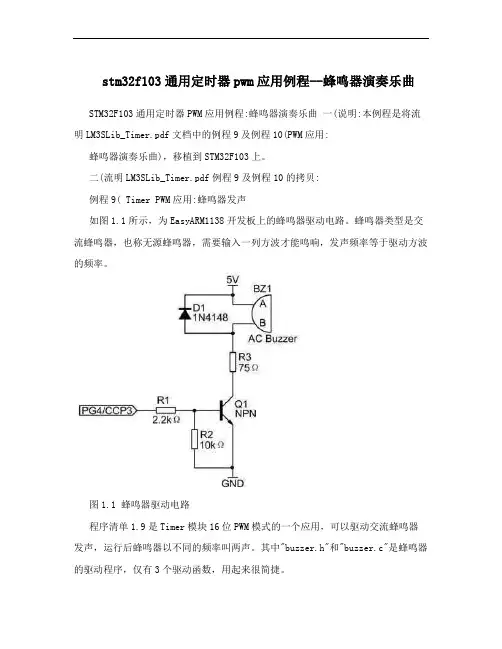
二(流明LM3SLib_Timer.pdf例程9及例程10的拷贝:例程9( Timer PWM应用:蜂鸣器发声如图1.1所示,为EasyARM1138开发板上的蜂鸣器驱动电路。
蜂鸣器类型是交流蜂鸣器,也称无源蜂鸣器,需要输入一列方波才能鸣响,发声频率等于驱动方波的频率。
图1.1 蜂鸣器驱动电路程序清单1.9是Timer模块16位PWM模式的一个应用,可以驱动交流蜂鸣器发声,运行后蜂鸣器以不同的频率叫两声。
其中"buzzer.h"和"buzzer.c"是蜂鸣器的驱动程序,仅有3个驱动函数,用起来很简捷。
程序清单1.9 Timer PWM应用:蜂鸣器发声文件:main.c#include "systemInit.h"#include "buzzer.h"// 主函数(程序入口)int main(void) {jtagWait(); // 防止JTAG失效,重要~clockInit(); // 时钟初始化:晶振,6MHzbuzzerInit(); // 蜂鸣器初始化buzzerSound(1500); // 蜂鸣器发出1500Hz声音SysCtlDelay(400* (TheSysClock / 3000)); // 延时约400ms buzzerSound(2000); // 蜂鸣器发出2000Hz声音SysCtlDelay(800* (TheSysClock / 3000)); // 延时约800ms buzzerQuiet( ); // 蜂鸣器静音for (;;) {}}文件:buzzer.h#ifndef __BUZZER_H__#define __BUZZER_H__// 蜂鸣器初始化extern void buzzerInit(void);// 蜂鸣器发出指定频率的声音extern void buzzerSound(unsigned short usFreq); // 蜂鸣器停止发声extern void buzzerQuiet(void);1#endif // __BUZZER_H__文件:buzzer.c#include "buzzer.h"#include <hw_types.h>#include <hw_memmap.h> #include <sysctl.h>#include <gpio.h>#include <timer.h>#define PART_LM3S1138#include <pin_map.h> #define SysCtlPeriEnable SysCtlPeripheralEnable #define GPIOPinTypeOut GPIOPinTypeGPIOOutput// 声明全局的系统时钟变量extern unsigned long TheSysClock;// 蜂鸣器初始化void buzzerInit(void){SysCtlPeriEnable(SYSCTL_PERIPH_TIMER1); // 使能TIMER1模块SysCtlPeriEnable(CCP3_PERIPH); // 使能CCP3所在的GPIO端口GPIOPinTypeTimer(CCP3_PORT, CCP3_PIN); // 设置相关管脚为Timer功能TimerConfigure(TIMER1_BASE, TIMER_CFG_16_BIT_PAIR | // 配置TimerB为16位PWM TIMER_CFG_B_PWM); }// 蜂鸣器发出指定频率的声音// usFreq是发声频率,取值 (系统时钟/65536)+1 , 20000,单位:Hz void buzzerSound(unsigned short usFreq) {unsigned long ulVal;if ((usFreq <= TheSysClock / 65536UL) || (usFreq > 20000)) {buzzerQuiet( );}else {GPIOPinTypeTimer(CCP3_PORT, CCP3_PIN); // 设置相关管脚为Timer功能ulVal = TheSysClock / usFreq;TimerLoadSet(TIMER1_BASE, TIMER_B, ulVal); // 设置TimerB初值TimerMatchSet(TIMER1_BASE, TIMER_B, ulVal / 2); // 设置TimerB匹配值TimerEnable(TIMER1_BASE, TIMER_B); // 使能TimerB计数 }}// 蜂鸣器停止发声void buzzerQuiet(void){TimerDisable(TIMER1_BASE, TIMER_B); // 禁止TimerB计数GPIOPinTypeOut(CCP3_PORT, CCP3_PIN); // 配置CCP3管脚为GPIO输出GPIOPinWrite(CCP3_PORT, CCP3_PIN, 0x00); // 使CCP3管脚输出低电平 } 例程10(Timer PWM应用:蜂鸣器演奏乐曲程序清单1.10是Timer模块16位PWM模式的一个应用,能驱动交流蜂鸣器演奏一首动听的乐曲《化蝶》(乐谱参见图1.2)。

第1篇一、实验目的1. 了解按键电路的工作原理。
2. 掌握蜂鸣器的工作原理及其控制方法。
3. 学习使用C语言进行嵌入式编程。
4. 培养动手实践能力和团队合作精神。
二、实验原理1. 按键电路:按键电路由按键、上拉电阻和下拉电阻组成。
当按键未被按下时,上拉电阻将输入端拉高;当按键被按下时,下拉电阻将输入端拉低。
2. 蜂鸣器电路:蜂鸣器是一种发声元件,其工作原理是利用电磁铁的磁力使振动膜片振动,从而产生声音。
蜂鸣器的控制主要通过改变输入信号的频率来实现。
3. 计数原理:通过按键输入信号,实现计数器的计数功能。
当按键被按下时,计数器加一;当按键被连续按下时,计数器的计数值随之增加。
三、实验器材1. 单片机开发板(如STC89C52)2. 按键3. 蜂鸣器4. 电阻5. 接线6. 电脑7. 调试软件(如Keil uVision)四、实验步骤1. 设计电路图:根据实验要求,设计按键、蜂鸣器和单片机的连接电路图。
2. 编写程序:使用C语言编写程序,实现按键计数和蜂鸣器控制功能。
3. 编译程序:将编写好的程序编译成机器码。
4. 烧录程序:将编译好的机器码烧录到单片机中。
5. 调试程序:通过调试软件对程序进行调试,确保程序正常运行。
6. 测试实验:将单片机连接到实验电路中,进行按键计数和蜂鸣器控制测试。
五、实验代码```cinclude <reg52.h>define uchar unsigned chardefine uint unsigned intsbit key = P3^2; // 按键连接到P3.2端口sbit buzzer = P1^0; // 蜂鸣器连接到P1.0端口uchar count = 0; // 计数器void delay(uint t) {uint i, j;for (i = 0; i < t; i++)for (j = 0; j < 127; j++);}void buzzer_on() {buzzer = 0; // 使蜂鸣器发声}void buzzer_off() {buzzer = 1; // 使蜂鸣器停止发声}void main() {while (1) {if (key == 0) { // 检测按键是否被按下delay(10); // 消抖if (key == 0) {count++; // 计数器加一buzzer_on(); // 使蜂鸣器发声delay(500); // 发声时间buzzer_off(); // 停止发声}}}}```六、实验结果与分析1. 当按键未被按下时,蜂鸣器不发声。