PY木床 游戏床 日本SG安规 自翻译简易版
- 格式:doc
- 大小:737.00 KB
- 文档页数:10
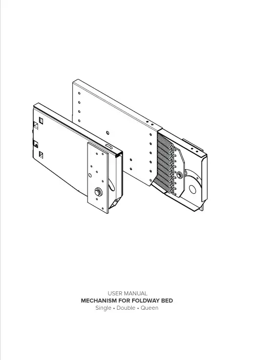
USER MANUAL MECHANISM FOR FOLDWAY BED Single • Double • Queen1.2.REMOVESLIDE TO OPENUnlock the mechanism.Open the mechanism.A B C161616494949382432525191919525252382432525222222555555382432525252525585858382432525200250343LEG 200*All dimensions are in mmLEG 250LEG 343WARRANTYTo make the mechanism work and to ensure the warranty of the product, ci r cled dimensions must be respected.Metal box3.Mount the metal box on the cabinet.SAFETY INFORMATION1.Be careful: the cabinet must be always fixed to the wall before starting to mount the mechanism.2.The screws to fix the mechanism to the furniture are not provided.The user is responsible to use the proper screws.3.It is mandatory to use all the 14 screws showed above to fix the metal boxes.A D161616190240333191919190240333222222190240333252525190240333225LEG 200*All dimensions are in mmLEG 250343LEG 343If door/panel thickness is less than22mm, it is strongly recommendedto use our plate to strengthen yourwooden box.Bed frameSpring boxDoor - panel4xM64.Mount the spring box on the bed frame.WARRANTYTo make the mechanism work and to ensure the warranty ofthe product, ci r cled dimensions must be respected.SAFETY INFORMATION5.Slide spring box into metal box.SLIDE IN6.Rotate the mechanism in horizontal position.7.Lock the two parts of the box.8.Rotate the bolt on the box’s back to regu-late the springs tension.BE AWAREBefore having mounted the feet, the bed frame must not be rotated more than 90°.BE AWARE1. Springs tension is correcly set when bed stops in each position the user leaves it.2. Springs of both left and right mechanisms should be evenly tensioned: apply the same turns on left and right bolts.3. Do not remove the screw completely.BE AWAREMechanism is certified to support a maximum of 105kg.With this weight the mechanism stops the bed door before it tou-ches the ground if dropped from closed position.ROTATE9.Fix the manual folding feet to the cabinet door.Manual folding foot200250343LEG 200LEG 250LEG 343ASSEMBLY STEPS FEET TYPESASSEMBLY - FINAL RESULTBE AWAREIt is possible to use the mechanism with different cabinet dimensions ONLY IF YOU CHECK:1. the mechanism rotation;2. the balance of the mechanism;3. the perfect closing of the cabinet door.1.Rotate the mechanism in horizontal position.DISASSEMBLY STEPSROTATE2.Unock the two parts of the box.REMOVE3.Rotate the mechanism in vertical position.ROTATESAFETY INFORMATION Two installers are needed to disassemble the product:while one person maintains the bed in horizontal position, the other one unlocks the mechanisms.DISASSEMBLY STEPS4xM6SLIDE4.Slide out spring boxes from metal boxes.5.Disassemble the spring boxes.。

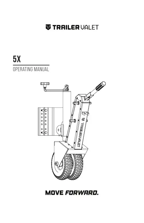
5X OPERATING MANUALOPERATING MANUALTABLE OF CONTENTSWARNING AND TABLE OF CONTENTS (2)IMPORTANT SAFETY INFORMATION (3)SPECIFICATIONS (4)WHAT’S IN THE BOX (5)ASSEMBL Y (6)OPERATING INSTRUCTIONS (7)MAINTENANCE (10)LIMITED MANUFACTURER’S WARRANTY (11)2IMPORTANT SAFETY INFORMATIONFailure to heed these markings may result in personal injury and/or property damage:1. DO NOT use the 5X on slopes and inclines beyond stated limits.2. DO NOT submerge the 5X in water (salt or fresh) or leave it in water for prolonged periods, since this can damage the gears and erode lubricants.3. DO NOT use your drill on the 5X’s high gear. (Attachment sold separately)4. Carefully read all instructions. The operator of the 5X must exercise common sense, caution, and full judgment when assessing situations not covered or cautioned in this manual.5. The 5X is designed for specific applications only. Trailer Valet will not be responsible for issues arising from modifications made onto the device. Do not modify the device or use the device for any application other than its intended purpose. Do not exceed the designated weight limits.6. Stay alert! Do not operate if you are tired. Do not operate the device while under the influence of drugs or alcohol. Read prescription warning labels to determine if the use of prescription drugs may impair your ability to operate the device.7. As with all devices with moving parts, do not wear excessively loose clothing as it may become caught, resulting in injury. Tie back and secure long hair.8. Have a second person guide your trailer’s movements while using the 5X to avoid property damage when necessary, especially in narrow or poorly visible areas.9. Operator and bystanders should never place any part of the body under or in the path of any portion of this product or the load being supported or moved.10. This product must be installed and used in strict accordance with these instructions.11. Always remember to set the brakes before leaving or if you are having trouble maintaining control of the trailer.12. Always read and understand your drill/driver operator’s manual and instructions.13. Before each use of the 5X, check for damaged parts. Carefully inspect the device for any part that appears to be damaged to determine if the device will operate properly. Check for alignment and secure mounting of all moving parts. If the device is neither aligned, secured, or both: DO NOT use the device.14. When servicing, use only factory replacement parts.15. The 5X is not intended to be used as a transport device for the implement it is attached to.16. Have wheel blocks in place before/after use and ready in case of emergency.17. Never exceed the maximum rated capacity. Refer to the operating manual or decals on the product to obtain rated capacity. If uncertain, contact Customer Support at (844) 846-9344oremail:************************.18. The 5X is designed for vertical loading. Excessive side forces may cause failure and must be avoided.19. The use of gloves is recommended while attaching the device to the trailer.20. The 5X is designed for use on solid surfaces. DO NOT use the product on excessively soft surfaces or muddy terrain as the device will not be able to gain traction. If there is no traction despite being on a solid surface, consider shifting more of the weight of your trailer forward.SAVE THESE INSTRUCTIONS3The Trailer Valet 5X is made of high strength steel and given a powder coat finish made to resist corrosion from the elements and marine use. When cared for properly, it will provide years of service. The 5X mounts to the side of trailer tongue. Once mounted to your trailer, the 5X makes maneuvering your trailer much easier than your old jack. Hitching and unhitching, leveling, and moving is now done with precision. The 5X is designed for trailers up to 5,000 lbs. The 5X is for use only on paved surfaces or compacted gravel and soils that are free of debris.Wheel size: 9.25 inchesJack range: 14 to 22 inches Tongue max weight: 500 lbs.Trailer max weight: 5,000 lbs.Weight: 50 lbs.Maximum dimensions: 29” H x 13” L x 7.5”Patented under US Patent number 6,619,671 and 6,739,601.Phone: (844) 846-9344Email:************************Website: thank you for your purchase!Congratulations on your purchase of the T railer Valet 5X. For your future reference please complete the owner’s record below:Purchase Date: ______________________Order No.:______________________Retailer:_____________________________Be sure to save your receipt and owner’s manual with warranty information in a safe place.4SPECIFICATIONSUpon removing items from packaging, it is very important to thoroughly inspect all parts of the system before using the device. Any part that is missing or damaged must be immediately replaced.****************************************************************************14. Bracket15. Bracket Clamps 16. Bracket Bolts (x4)1. Axle Yoke Compartment2. Jack/Jack Tube3. Jack Crank4. Brake Cap5. Steering/Brake Handle6. Side Plates7. Gear Covers8. Low Gear Driveshaft 9. High Gear Driveshaft 10. Axle/ Screw Assembly 11. Rims 12. Tire13. Brake Handle Clip17. Crank Handle18. Rotation/Security Pin19. Stow/Clevis Pin & Cotter Pin 20. Security Bolt A. The Trailer Valet 5XB. Mount Bracket KitC. Accessory PackD. Cleaning Cloth5WHAT’S IN THE BOX1351748139101819151614111267220STEP 1: SET UPWhen installing the T railer Valet 5X, the unit must be installed while the weight of the trailer is supported by an existing jack.Having wheel chocks in place during connection will insure a safe install.Raise the trailer tongue to where the coupler is about 16 inches off the ground to give adequate space to attach the dolly. During installation, the Steering Handle must be secured to the safety clip to ensure the brake is engaged at all times.STEP 2: POSITIONINGThe mounting bracket has 7 holes to fit a variety of trailer frames. Be sure that you have at least 8 inches of free space for the mounting bracket to be fitted onto your trailer frame.Choose a location on the tongue frame where the 5X can freely rotate from its vertical position to its horizontal stow position.The 5X is only to be installed on trailer tongues that arerectangular in profile. Cylindrical frames are not compatible with the 5X as it will rotate, allowing the trailer to drop.STEP 3: CONNECTIONPlace the Mounting Bracket and clamps ontoIt is now recommended that you ensure that there is adequate height to install the unit. The trailer should be high enough that, when the frame is level, there is enough space for the unit to be at least one inch off the ground once attached to the bracket. If there is not enough space, adjust the placement of the bracket on your trailer frame.NOTE: While it is recommended that thebracket is installed with the attachment point in the low position for stability reasons, the bracket can be flipped prior to install if the space is required.After the bracket is positioned, evenly and firmly tighten the four bolts to secure the Mount Bracket.6ASSEMBLYUsing the Trailer Valet with the jack extended will cause excessive wear on the jack and possible result in injury and/or property damage. Always lower the Trailer tongue to its lowest position on the unit or until your trailer frame is level with the ground.STEP 5: ATTACHING DRIVEROption 1: Manual OperationAttach the Drive Handle to the low or high gear Driveshaft.The low gear drive shaft (located nearer to the top of the unit) allows greater control of the unit and may assist in moving into/through very tight spots.The high gear drive shaft (located lower on the unit) allows for greater movement tocover distance. Choose your gear accordingOption 2: Drill Adapter (sold separately)The Drill Adapter can be used with any standard 18 to 24 volt, 1⁄2 inch chuck, commercial drill. Corded drills and impact drills are not recommended.Step 4: TESTING THE ASSEMBL YRemove the rotation pin from the bottom of the jack and, if the trailer is attached to a towing vehicle, turn the crank to raise the trailer up off the hitch. Move the hitch from under your coupler.NOTE: Always ensure the operator and bystanders are aware of load stability. Remember to also disconnect any towing safety chains, the brake-turn signal wire harness, and any other connections.Raise your pre-existing trailer jack and lower the 5X unit until your trailer frame is preferably level with the ground. Y our pre-existing trailer jack should be raised until it sits at about three inches above the ground and the trailer’s weight is supported entirely by the Trailer Valet. Keep yourtrailer jack close to the ground to buffer any unexpected failures.Videos are available on the T railer Valet website if you need a visual guide to install or use your Trailer Valet.Knowing the proper techniques to operate your 5X can help keep you and others around you safe. In this guide, you are shown the basic fundamentals for effective operations. However, it is up to you to analyze the situation and make the decisions necessary for the proper use of your 5X. Apply your knowledge of your 5X and the basic fundamentals you have practiced to adjust your techniques to each unique situation.7Slot the Drill Adapter in your Drill chuck and secure tightly to avoid the adapter slipping. Align and insert the Drill Adapter to the low gear Driveshaft. Use of an electric drill is not recommended on the high gear.NOTE: If you are using a cordless drill, be sure your battery pack is fully charged before use. Follow your drill/driver manufacturer’s recommendation.NOTE: When attempting to move up any incline, it is recommended that the trailer be moved without the use of the drill adapter. Using the adapter when leading your trailer down an incline may result in damage to your drill.Visit our website to see a video on how to use your drill attachment to move your 5X.STEP 6: OPERATING THE DEVICENOTE: If your trailer has built-in brakes, theymust be disengaged prior to operation of the 5X. Consult your trailer manufacturer’s manual/ instructions on temporary brake release. If this is not available to you, please contact Trailer Valet Customer Support through phone or email for assistance.When ready to operate the device, be sure to have one hand firmly gripped on the brake/steering handle and the other hand firmly holding the drill/driver.Lift the Steering Handle until the brake is disengaged and begin cranking. TheSteering Handle must be held up firmly at all times when moving the trailer.Hold the drill firmly when engaging. Ifusing an electric drill, it will have high initial torque if the drill trigger is pulled rather than squeezed. Begin to move the trailer as slowly as capable and carefully increase the power up to an appropriate speed when using the Drill Attachment.NOTE: It is important that you steer the device only when you are cranking and the trailer is moving. Attempting to turn the Steering/Brake Handle at a dead stop will place excessive stress on a single tire which may result in damage.NOTE: When attempting to make sharp turns (E.G. 90° rotation) from a stationary position, crank the 5X back and forth while turning until the unit is in the desired position. Then, proceed to make the turn.DO NOT use the 5X on slopes and inclines exceeding a strict maximum of 10 degrees on a paved/ concrete surface. This rating is subject to factors including, but not limited to, alternate surfaces, weight distribution, change in weight capacity, and use on multi-axle trailers. If you have any questions concerning the use of your 5X on a slope or incline, please contact us at (844) 846-9344 or email us at: support@NOTE: Use of a power drill is inadvisable for movement upon any incline.When parking your trailer, slow to a gradual stop before engaging the brake. Braking with momentum may result in damage. Be sure to always engage the brake when not operating the 5X. When parked, secure with wheel chocks.8STEP 7: STORING THE DEVICE1. Remove the drill/drive handle.2. Lower your trailer’s existing jack until the T railer Valet is above the ground.3. Insert the rotation pin into the jack assembly.4. Choose between the following two options:Option 1: Remove the 5X Remove the stow pin and detach the unit from the mounting bracket. Restore theOption 2: Keep the 5X Attached to the T railerT ongueCrank the jack handle until the unit jack isfully withdrawn. Then, remove the cotterand clevis/stow pin and rotate the unit 90degrees with the “T railer Valet” logo facing up.Restore the clevis/stow and rotation pinswhile the unit remains attached to themounting bracket. This will allow the 5X toremain attached to the trailer while beingtowed.The T railer Valet 5X comes with a securitybolt (part 21) that is an option to securethe device while trailering. If you travel withthe 5X and choose to use it, the bolt slotsthrough the back of the mounting bracketand threads into the tube of the 5X jack.Failure to lock in the pinsand bolt prior to trailering with the unit inthe stow position may result in the unitbecoming dislodged during movement.9Additional Tips:• The Trailer Valet 5X is made of high strength steel and given a powder coat finish made to resist corrosion. However, if the device is used in a marine environment or where road salt is encountered, rinse off the interior and exterior with fresh water and allow to dry. DO NOT SUBMERGE THE 5X as this can damage the gears and erode lubricants.• After each use, wipe exterior surfaces with a clean cloth.10MAINTENANCELIMITED MANUFACTURER’S WARRANTYSuperT ech S Corp warrants for one year from the purchase date that the product will be in working condition and will be free from manufacturing defects, provided that installation and use of the product is in accordance with product instructions. This warranty is only made to the original consumer purchaser and is non-transferable.ALL OTHER WARRANTIES IMPLIED OR EXPRESSED ARE HEREBY DISCLAIMED.THIS WARRANTY DOES NOT COVER:1. Normal wear and tear or normal aging of the product;2. Consumable parts designed to diminish over time, unless failure occurred due to a manufacturing defect;3. Cosmetic damage, including but not limited to scratches and dents;4. Damage through accident, abuse, neglect, misuse, natural events, or other external causes;5. Damage through misapplication, overloading, or improper installation;6. Damage due to improper maintenance and repair; and/or7. Product alterations.LIMITATION OF LIABILITY:EXCEPT AS PROVIDED IN THIS WARRANTY AND TO THE MAXIMUM EXTENT PERMITTED BY LAW, SUPERTECH IS NOT RESPONSIBLE FOR ANY DIRECT, INCIDENTAL, CONSEQUENTIAL DAMAGES, OR INJURIES RESULTING FROM ANY BREACH OF WARRANTY OR CONDITION; INCLUDING, BUT NOT LIMITED TO, LOSS OF USE, LOSS OF REVENUE, LOSS OF ACTUAL OR ANTICIPATED PROFITS, LOSS OF BUSINESS, LOSS OF OPPORTUNITY, LOSS OF GOOD WILL, LOSS OF REPUTATION, OR ANY DIRECT, INDIRECT, OR CONSEQUENTIAL LOSS OR DAMAGE WHATSOEVER CAUSED, INCLUDING THE REPLACEMENT OF EQUIPMENT AND PROPERTY.CUSTOMER RESPONSIBILITIES:Customers may be required to provide proof of purchase date, respond to questions designed to assist with diagnosing potential issues, and follow Trailer Valet’s directions to make a claim on your warranty.TO MAKE A WARRANTY CLAIM:Contact us either through:PHONE: (844) 846-9344EMAIL:************************WEBSITE: TRAILER VALET SHALL HAVE THE EXCLUSIVE RIGHT TO DETERMINE IF A UNIT IS COVERED UNDER ITS LIMITED MANUFACTURER’S WARRANTY.SEVERABILITY:The invalidity, illegality, or unenforceability of any provision of this warranty shall not render the other provisions invalid, illegal, or unenforceable.GOVERNING LAW AND JURISDICTIONThis warranty shall be governed by the laws of the State of California. The courts of California shall have the exclusive right to adjudicate any disputes arising under or in connection to this warranty.11SUPERTECH S. CORP .Customer Service: (844) 846-9344Email:************************ Copyright 2022 by Supertech S. Corporation. All rights reserved. No portion of this manual or any artwork contained herein may be reproduced in any shape or form without the express written consent of Supertech S. Corporation.For further information or if you have any questions, please contact:。
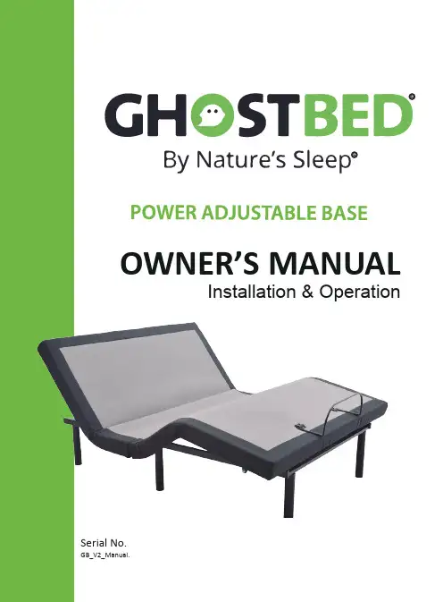
OWNER’S MANUALInstallation & OperationSerial No.GB_V2_Manual.Safety & Warranty Warnings (01)Parts List (02)GhostBed Electronics Quick Reference Guide (03)Installa tion Guide (04)GhostBed Remote Control Ins tructions (07)Se tting Programmable P ositions and Pairing Remote (08)Special Func tion (09)Synchronizing Two Bases (10)Headboard Bracket Installa tion Guide (11)Tr oubleshooting (12)READ THE FOLLOWING INFORMATION CAREFULLY BEFORE USING THIS PRODUCTIf unable to understand warnings, cautions, and/or instructions, contact the dealer or technical personnelif applicable, before attempting to use the equipment. Otherwise, injury or damage may result.SAFETY WARNINGS:• Do not use bed outdoors.• Do not use bed near explosives.• Using bed with oxygen administering equipment other than the • When using nasal or masked type administering equipment, route and secure oxygen or air tubing properly to ensure that tubing does not become entangled or damaged during normal operation of the bed.• Use caution when having liquids in or around the bed to ensure no spilling occurs. In case of spillage, stand in a dry, clean area of the area around bed to dry thoroughly before using the electric controls again. Do not eat or drink hot liquids while operating the bed.• This appliance is not intended for use by persons (including children) with reduced physical, sensory or mental capabilities, or lack of experience and knowledge, unless they have been given supervision or instructions concerning use of the appliance by a person responsible for their safety.• Do not allow children or individuals with disabilities to operate the bed without adult supervision.• Do not allow any person or pet under the bed at any time.• During bed operation, make sure body is positioned within the bed when operating bed functions.WARRANTY WARNINGS:Do not open or tamper with control box, motors, or remote (with the exception of battery compartments). The warranty will be void if the internal workings of these components are tampered with.Product Rating:The motors are not designed to operate continuously for more than [2] minutes in an [18] minute time period or approximately 10% duty cycle. Attempting to circumvent or exceed this rating will shorten the life expectancy of the foundation and may void the warranty.Operating Information:• After power foundation assembly is completed, operate remote control to ensure proper functions.• Keep moving parts free of obstruction during bed operation (including sheets, clothing, tubing, wiring, and products using electric power cords).• Distribute body weight evenly over bed surface. Do not place entire weight on head or foot sections of the bed, during repositioning and entering or exiting bed.Hospital Use Disclaimer:This power foundation is designed for residential use only. It is not approved for hospital use and does not comply with hospital standards.Weight Limits:This product is not rated to support weights in excess of 750 pounds inclusive of the mattress and bedding. The bed will structurally support this weight, provided it is evenly distributed across the foundation. The power foundation is not designed to support or lift this amount in the head or foot sections alone. Exceeding this weight restriction could damage the bed and/or cause injury and willvoid the warranty.RADIO FREQUENCY: 2.4 GHzAttached tothebedframeAll electronics and components that need to be installed are located in boxes under the foundation orattached to the frame. Before discarding the packing materials, ensure that all the parts are accounted for.BBed Legs (6)CPower Supply (1)DPower Cord (1)FRetainer Bar (1)AAAA Batteries (2)ERemote Control (1)Sync cord ( TXL model only )GGHOSTBED WIRELESS OVERVIEWGhostBed Adjustable Power Base Electronics Quick Reference GuideFoot MotorUSB PortsHead Massage MotorHead MotorControl Box LED LightF o o t M a s sa g e M o t o r rRemoteMotorLED LightFoot MotorHead MotorControl BoxUSB PortsPower SupplyPower CordHead MassageFoot Massage MotorNote: For safety reasons, lifting of the adjustable bed frame must be performed by two (2) people; and theSTEP 1Lift the folded bed frame unit out of the shipping cartonSTEP 2Lower the head and foot frame pieces with their topside facing downward.STEP 3Using a pair of scissors (not included), cut the tiesto remove all accessory boxes and retainer bar frominside the unit.Attaching the bed legsRemove the six (6) bed legs from the accessory box. Hand tighten the legs by threading them clockwise into the pre-threaded holes on the bed frame.Installing the retainer barSTEP 1Turn the bed frame over carefully, top side up.STEP 2Insert the ends of the retainer bar into the quickconnect brackets located at the foot of the bed.Setting up the electronicsSTEP 1STEP 2Take out the power supply and the power cord from the accessory box.Connect the power cord from the control box to thepower supply.STEP 3Connect the power cord that was packaged with thepower supply to the power supply.STEP 4STEP 5Plug the power cord into a working electrical outlet.The LED lights under the base will flash for 10 seconds .Install the two (2) AAA batteries into the remote control.STEP 6Confirm the remote control works by pressing the lift buttons. Installation for single or independent operation of the bed frame is now complete.PAIRING REMOTEThe wireless power bed has a programmable feature that allows you to save custom positions. Please read all the instructions below before setting your custom presets on the remote.STEP 1STEP 3Adjust the head and foot to your desired position.To adjust the saved position, repeat steps 1 and 2 and the newposition will be saved.STEP 1them when needed.The original remote that comes in the box is already paired to the foundation. No further action is required. In the event that the remote is not paired with the foundation, follow the steps below.STEP 2Plug the power cord to the power source.button located on the side of the control box 2 times and then press the “PAIR” button located on the remote.Your adjustable bed frame comes with a power supply that, when powered with two new 9V batteries, supports the emergency power down feature.The batteries are not included and work for a single use only.If a power failure occurs while the head and/or foot sections are raised, do thefollowing:Emergency power downSTEP 1Install two (2) new 9V batteries in the batterycompartment of the power supply.STEP 2Press the flat position on the remote if there is nopower from the electrical outlet.If simultaneous operation of two foundations is desired, please read the instructions.STEP 1STE Light on Set Remote B operate both bases too.be able to operate both beds simultaneously.Note:been separated from the remote A. STEP 2Plug the synchronizing cable into 2 control boxes of 2 bases.simultaneous operated by Remote A.Base B Base AHeadboard brackets are an optional accessory and are not included.A 1/2'' (13 mm) socket and 1/2'' (13 mm) crescent wrench are necessary to complete installation.STEP 1STEP 3STEP 2The headboard bracket will have 2 long slots to accomodate anyframe type. Align the appropiate slots on the bracket with the holeson the bed. Use long bolts and nuts to secure the bracket. Makesure the bolts are tight. You may now connect your headboard to the attachment plates using the remaining short bolts and nuts to secure it to the brackets. The heads of the bolts will face outward. Use a 1/2" (13 mm) socket and 1/2" (13 mm) wrench to tighten the bolts.To put the T-Bracket and Headboard Bracket together, you will need (2) short bolts and (2) nuts. Slip the bolts through the holes from T-Bracket to Headboard Bracket with the head of bolt facing outward. Use 1/2'' (13mm) socket and 1/2'' (13mm) wrench to tighten the bolts.In the event that the power foundation fails to operate, assess the symptoms and possible solutionsprovided in the chart below.In the event that the power foundation fails to operate, assess the symptoms and possible solutionsprovided in the chart below.SYMPTOMS SOLUTIONSHead & Foot lift function has minor interference durling operation.A clicking noise is heard under the bed when raising or lowering.Check batteries in wireless remote control, replace with two (2) new AAA batteries if necessary.Make sure that you are following the duty cycle of the motors (do not operate more than two minutes over a 18-minute period, or approximately 10% duty cycle).Press the lift buttons squarely and accurately.Wireless remote control may be experiencing common Radio Frequency Interference from other radio transmitting devices. Wait several seconds, and then try pressing appropriate button again, See FCC Compliance Statement on page 1 of this guide.This is normal. The lift motor relays “click” when they are engaged. No action is required.。
英国标准 BS EN716-1:1996家具-家用儿童游戏床和可折叠游戏床Part1.安全要求欧洲标准EN716-1:1995具有英国国家标准的地位委员会对此英国标准负责此英国标准的筹备委托给了技术委员会CCW/52.以下团体中的儿童游戏床、双层床及床垫具有代表性:科学家咨询协会;婴儿设备租用者协会;婴儿产品协会;英国婴儿车零售商协会;英国零售财团;英国玩具爱好协会;化工业协会;儿童意外事故预防协会;BSI消费者政策委员会;消费者协会;贸易工业部门(消费者安全协会);贸易工业部门(政府化学家实验室);家具工业研究协会;贸易标准管理机构;意外事故预防协会;青年招待所协会(英国及威尔士)出版后修正发行概述下面的表格指明了每页的最新版,版本1指明此页已经为第一次修正而引进.随后的版本号码指明是更新页.替换页上的垂直边线指明最新的改变(修正,添加,删除).内容委员会责任国家前言前言EN716-1正文国家前言此标准由技术委员会CCM/52起草制定,是EN716-1:1995家具-家用儿童游戏床及可折叠游戏床第一部分安全要求的英文版,由欧洲标准化委员会(CEN)出版。
它取代了撤消的BS1753:1987和BS7423:1991。
EN716-1是国际讨论的成果。
参考资料出版标准涉及的英国标准EN71-1:1998 BS5665:玩具安全Part1:1989机械及物理性质EN71-3:1994 BS EN71-3:玩具安全Part3:1995特定元素的迁移EN716-2:1994 BS EN716-2:家具家用儿童游戏床及可折叠游戏床Part2:1996测试方法符合英国标准并不意味着获得法律规范的豁免。
欧洲标准EN716-1November 1995ICS 97.140家具-家用儿童游戏床和可折叠游戏床-Part1.安全要求此欧洲标准经由CEN于1995年10月11日核准。
CEN会员有义务遵守CEN/CENELEC国际规定,此规定为授予此欧洲标准国家标准的地位制定了相关条件。

木工家具行业经常使用英语辞汇翻译对照表1、家具种类AAdjustable bed 可调床Air bed 气床Anti-slip strip for stairs (儿童床)防滑楼梯冲击扶手Antique furniture 古式家具Antique reproduction furniture 仿古家具Armchair 扶手椅BBaby crib 婴儿床Backless wall-unit 不设背板的壁橱Bamboo furniture 竹家具Banqueting chair 宴会椅Barstool 吧椅Bathroom accessories 浴室配套装置Bathroom combination 浴室组合柜Bathroom consoles 浴室多用架Bathroom furniture 浴室家具Bathroom vanity 浴室盥洗台Batten door 板条门Bed base床架,床套Bed base set 成套床架Bedroom suite 卧室系列家具Bedstead 床架Bentwood furniture 曲木家具Beside table 床头柜Birch door 桦木门Board-room and conference table 会议桌Bookcase 书柜Bookshelf 书架Built-in kitchen 配套厨房家具Bunk 双层床Bunk bed 双层床CCabin bed 儿童多功能床Cabin furniture for ships 船用家具Canopy bed 带天篷的床,四柱床CD-video storage cabinet边音响组合柜Chair with castors 脚轮椅Changing table 可调桌Chest of drawers 多屉橱柜Child cot 童床Children’s bed 儿童床Children’s bedroom suite 儿童卧房系列家具Children’s chair 儿童椅CKD(complete knock down) 整体拆装式家具Clothes rail 挂衣杆Cocktail cabinet 吧柜,酒柜Cocktail table 鸡尾酒桌Coffee table 茶几,咖啡桌Combine-unit 组合柜Composite furniture 复合家具Console 小桌Console table (装在墙上的)蜗形腿台桌Contract furniture 订做家具,承建家具Contract programmes 订做家具Corner sofa suite 拐角扶杆Cot 童床(婴儿床)Couch 长沙发椅Cupboard 橱柜Cupboard wall unit for flat 套房衣柜Curtain 窗帘,挂帘Customized furniture 订做家具DDecorative lighting 装饰灯具Dining room furniture 餐厅家具Dining room set 起居室配套家具Dining table 餐桌Divan 长沙发,沙发床Dividing wall and fitted wall unit 隔墙板及系列DIY furniture 自装式家具Double-bed 双人床Double function sofa-bed 双人沙发床Double sided mirror 双面镜Draughtsman chair 吧椅Drawer 抽屉Dressing table 打扮台EEasy chair 轻便椅End table 茶几Entrance hall furniture 门厅家具Exterior door户外门FFiling cabinet 文件柜Fireplace壁炉Fitment 固定家具Fitting 家居用品Flap 翻门Flower stand 花架Flush door 平面门,全板门Folding chair 折叠椅Folding furniture 折叠家具Folk furniture 民间家具Foot-stool 踏脚凳Framed mirror 带框镜子French-type furniture 模式家具French cabinet 法式桌椅弯脚French door 玻璃门Function sofa多功能沙发椅Furniture for bedrooms 卧室家具Furniture for public premises 公开场合家具GGame table 玩具桌Gate-leg table折叠桌Glass cabinet 玻璃陈列柜Glass case玻璃陈列柜Glass unit and container 玻璃容器制品Glazed door 玻璃门HHall furniture 厅房家具Hat and coat stand 衣帽架Headboard 床头Heirloom quality furniture 家传家具High bed 儿童高脚床(不带屉柜)High chair 高脚椅Highback executive chair 高背办公椅Home furniture 家庭家具,民用家具Home office furniture 家庭办公家具Hotel furniture 酒店家具Household furniture 家庭家具Hutch碗架IInstitutional furniture 风俗家具,公用家具JJunior desk chair 学生书桌椅KKitchen block /kitchen rock 厨房地砖Kitchen cabinet 餐具柜Kitchen chair, stool and bench 厨房椅、圆凳及条椅Kitchen fitment 厨房固定家具Kitchen table 厨房餐桌Kitchen unit 厨房成套家具LLamp table 灯桌Lath grid 板条格Ledged door 直板门Link chair 写字板椅Living room furniture 起居室家具Locker 衣帽柜Lounge furniture 客厅家具Louvered door 百叶窗柜门Lowback executive chair 低背办公椅Lowback guest chair 低背宾客椅Lowback visitor chair 低背接待椅MManagerial mediumback chair 中背领导椅Margined flush door 镶边平板门Mattress 床垫,席梦思Mediumback executive chair 中背办公椅Metal furniture金属家具Mirror door 玻璃门Mirror for chest of drawers 多屉柜打扮镜Multi-purpose sofa 多用沙发Multi-purpose table 多用桌NNest 茶几OOccasional furniture 配套家具,休闲家具Occasional table 休闲桌Office furniture 办公家具Office seating 办公座椅Office table 办公桌PPartition wall 隔间Pembroke table 折面桌Planters chair 园艺工用椅Plastic furniture 塑料家具Play furniture 娱乐家具Presidential highback chair 高背办公椅Pull-out table 伸缩餐具RRattan furniture 藤家具Recliner 躺椅Refectory table长餐桌Rocking chair 摇摆椅Rotary chair 转椅Rustic style furniture 乡村风格家具SSchool table 课桌Screen 屏风Seat痤椅Seating element 痤垫Secretarial chair 秘书椅3-section mirror 三面打扮镜semi-CKD 半拆装家具serving table送餐桌shelving combination2、家具机械Aaccessory equipment 附属设备adhesion test instrument for the wood coating 木材涂层附着力测定仪adz(e) 手斧,刮刀air brake 空气制动器,气闸air compressor 空气紧缩机air conditioning unit 风向调剂器air nailer 风动钉钉机air operated automatic control 气动自动操纵air tacker气(风)动钉钉机air tool 风动工具automatic band saw sharpener 带锯自动锉锯机automatic circular saw sharpener 自动锉(圆)锯机automatic controlled machine 自控机床automatic copy shaper 自动仿型刨边机(单刀)automatic copy shaper(double heads)(with splash guard) 自动仿型刨边机(双轴)(附平安门)automatic feeder for veneer dryer 单板干燥机的自动填料机automatic hydraulic backnife wooden lathe 全自动液压背刀式木工车床automatic loader and unloader 自动装卸机automatic rotary table shaper 自动转台式成型机automatic sponge drum sander 自动鼓式海绵砂光机automatic strake belt sander 自动带式砂光机automatic stroke belt sander 自动(抚摸)砂光机automatic tapping and screwing machine 自动攻牙锁螺丝机automatic turning sander 全自动砂光机,自动圆棒砂光机automatic wide-belt sander 宽带砂光机BBack and arm impact test machine 椅背扶手冲击实验机balance cut-off saw 平稳截断锯Band and circular saw sharpener 带锯圆面积锯两用锉锯机Band resaw 再分带锯机Band saw 带锯Band saw clamp 带锯夹Band saw machine 带锯机Band saw machine with auto-feed carriage 带锯机附自动填料传送车Band saw machine with hand-feed carriage 带锯机附手扒送料车Band saw sharpener 带锯磨锯机Band saw shear 带锯剪(截)机Band saw slasher 多带横切锯Band saw stretcher 带锯滚压机Band saw welding clamp接锯机Band sawing 带锯制材Band scroll saw 细木工带锯,曲线带锯Barefaced tenon 裸面榫Bark-peeler 剥皮机Barking drum 鼓式剥皮机Barking machine 剥皮机Belt conveyor 带式传送器Belt drier 带式干燥机Belt drive 皮带传动Belt grinder 带式磨床Belt sander 带式砂光机Bentwood forming machinery曲木成型机Bevel saw 斜面锯Bifurcated rivet 开叉钉Bit 齿片,钻头Blade 锯条Block plane 短刨Blower通风机,鼓风机Blower kiln 鼓风式干燥窑Bobbin sander 轴式砂光机Body press (家具)装配压床Boring machine 钻床Bow saw 弓锯Brash chopper 枝梢切断机Breathing veneer drier 呼吸式单板干燥机Buffing machine 抛光机Business item 产品Butting saw 截锯,齐头锯CCabinet whole-plant equipment 橱柜整厂设备Carbide tool grinder 炭素钢刀具研磨机Carving machine 雕刻机Centerless sander 圆棒砂光机Centrifugal blower 离心通风机Chain-belt conveyer veneer drier 网带式单项式板干燥机Chain mortiser 插床Chain saw 链锯Chain saw machine 链锯机Chair aim static load test machine 椅扶手静荷实验机Chair back and arm impact test machine 椅背扶手冲击实验机Chair back static load test machine 座椅靠背静荷实验机Chair leg static load test machine椅腿静荷实验机Chair stability test machine座椅靠背耐久性实验机Chair whole-plant equipment 椅子整厂设备Chip board press 碎木板压合机Chip edger 双削齐边锯Chromometer 比色机Circular gang-saw 圆排锯Circular saw bench 简单圆面积锯机Circular saw bench for band feed ripping 手工送料纵切圆锯机Circular-saw sharpener 圆锯锉锯机Coating adhesion test instrument 漆膜附着力实验仪Coating impact instrument 漆膜冲击仪Coating surface impact instrument漆膜表面冲击仪Concave plane 凹底刨Concave saw 凹面(圆)锯Conveyor输送机Copier 复印机Corner locking machine 锁角机Cross cut band saw machine 横切带锯Cup type wheel stone机碗形砂轮Cup wheel杯形砂轮Curtain flow coater 淋幕式平面涂装机Custom 订做Customized solutions 订做胶水Cut-to –size saw 裁板锯Cutting block组合铣刀Cutting head 刀座,刀头Cutting jip 切削夹具Cylinder saw 桶形锯,圆桶锯Cylindircal saw 圆桶锯DDado head 组合刀头Debarder 剥皮机Deck planer大型电刨Decorative tip 装饰物Disc and spindle sander 盘式轴式联合砂光设备Disc planer 圆盘刨Disc sander 圆盘砂光机Door whole-plant equipment 门斗整厂设备Double band saw双边带锯Double belt sander 双边砂光机Double bevel cutter 双斜刨刀Double-edge cutting band saw 双边齿带锯Double-side planer双面刨木机double spindle shaper 双轴铣床Double surface oscillating curve sander 双面震动曲型杪光机Double surface planer双面刨Double surfacer 双(面)压刨Double-swage(set)saw 双压料锯Double thicknesser 双(面)压刨Dovetail machine 鸠尾榫机Dowel making machine暗榫(加工)机Drag saw sharpener狐尾机,锉锯机Drawer durability test machine 抽屉耐久性实验机Dresser 砂轮修整器,砂轮刀Drop test machine 跌落实验机Drum barker 滚筒剥皮机Drum sander 滚筒砂光机Drunken saw 摇摆(圆)锯Dust cleaner conveyor 粉尘清除输送机Dust collector 集尘器3. 家具木材AAbele银白杨Abnormal wood 异样(木)材Acoustic acid board 吸音纤维板Acoustical board 吸(隔)音板Adjustable template 可调剂的样板Adult wood 成年材African blackwood 非洲黑木黄檀African ebony 非洲乌木African mabogany 非洲桃花心木African padauk 非洲紫檀Aging 老化,陈化Air drying 大气干燥Air seasoning 天然干燥Alaska fir 阿拉斯加冷杉木Alaska yellow cedar 阿拉斯加柏木Alder 赤杨类American ash 美国白蜡木American beech 美国山毛榉American eim 美国榆,白榆American plane 美国悬铃木American tulipwood美国鹅掌揪Annual ring 年轮Apron 望板Armor-plywood 金属贴面板Arris 棱Artificial slabs人造板Artificial timber 人造木材Ash 白蜡木Aspen 白杨类BBabool 阿拉伯胶树Back 背板Back board背板Back veneer 衬板Bald cypress 落羽杉Bamboo 竹子Basswood 椴木,美国椴木Batten board 条板心细木工板Beech 山毛榉木Beech parquet 山毛榉拼花地板Bent wood (弯)曲木Birch 白桦,Birdseye maple雀眼枫木板Block 塞角Block floor 拼花地板Blockboard 细工木板Board 板材Bottom 底板Bowing 顺弯Branch wood 枝条材Brazilian mahogany 巴西桃花心木Bright sap 净面边材,无皮边材Broad leaf wood 阔叶材,硬材Brown ash 美国深色白蜡木Burl 树疤,树瘤CCaul 垫板,衬板Cedar 雪松,杉木Ceylon ebony乌木Cherry 樱桃木Chile pine 智利松Chinese chi (中国)漆树Chip 木屑# 1 common 普一级#2 common 普二级compreg 胶压木compressed wood 紧缩木coniferous species 针叶树种continuous layer board 多层板cork 软木cottonwood 三角叶杨,杨木(毛白杨类)crook 弯曲木cross rail 拉档crotch 丫权cupping 翘弯curly birch 皱纹桦木板curved laminated wood 弯曲层积材curved plywood曲型合板cypress针叶树DDado 护墙板,墙裙Damp room panel 防潮镶板Decay 初腐Deciduous species 阔叶树种Décor panel镶板,装饰板Delta wood 多层木Densified wood 强化木材Density of wood 木材密度Dent啃头Depth of cut 切削量(深度)Diffuse porous wood 散孔材Dimension 规格Dimension stock规格材Dimple djohar 波纹Door frame 鸡翅木Door lining 门框Dovetail 门衬板Dowel 燕尾榫Drawer front 圆榫Drawer side 屉旁板Dressed timber净材EEastern cottonwood (美国)东部杨木Eastern hemlock (加拿大)铁杉Eastern larch 落叶松Eastern white pine (美国)白松Ebony 乌木Edge cutting 封边Elm 榆木Elm burl 榆木树瘤薄木板End cutting 截头English plane 英国悬铃木Eucalyptus 桉木,桉树(类)Eucalyptus pom 柠檬铁皮桉木板Europe cherry 欧洲樱桃木板Eropean ash 欧洲白蜡木European beech 欧洲桦木European birch 欧洲桦木European chestnut 欧洲栗木European hop-hornbeam 欧洲穗子榆European horse-chestnut 欧洲七叶树European larch 欧洲落叶松European lime 欧洲椴木European spruce 欧洲云杉European yew 欧洲紫杉Excelsior-board 木丝板Exotics 外来木Exterior plywood 室外用胶合板HFace veneer 表面单板FAS 一级和二级FAX 1F 单面一级Fibre board纤维板Fiddle back提琴背(板)Fiddle butt 乐器用材Figured 影木Figured sycomore 梧桐影木Fine wood board 纤维板Flakeboard 碎料板Flakes 薄片刨花Flame-retardant fibre building board 耐火纤维板Flat-grain lumber 平切纹板材Flooring 地板Flush panel 平(光)镶板Formed plywood 模压(成型)胶合板Frame core flush panel 中空合板From sustainable forests 来自可持续进展的丛林Furniture dimension stock 家具规格材Furniture plywood家具胶合板Furniture veneer制作家具用的薄片GGap 离缝Giant cedar (美国)侧柏Gloss 光泽度Grade 品级Grade of lumber 成材品级Graded分品级Grain 纹理HHackberry 朴树Band selected 手工挑选Hard board 硬质纤维板Hard maple 硬枫木,械树Hardy catapa (美国)梓树Heat board 心板Hickory 山核桃木High-density plywood 紧缩胶合板,高密度胶合板High gloss 超光泽度High moisture resistant(HMR) 高强度抗湿Hipboard 细木工板Hole drilling 打眼Honey-comb core plywood 蜂窝心胶合板Huanghauli wood 黄花梨木IIdentification of timbers 木材识别Imitation wood 仿造材Imported timber 入口材Impregnated wood (合成树脂)浸渍木Indian camphor 印度樟木Indian chestnut 印度栗木Indian cinnamon印度肉桂Indian ebony 印度乌木Indian “laurel” 印度“月桂树”Insect attack虫眼Inserting panel 装板Install wood strip flooring 安装地板条JJapanese beech 日本山毛榉Japanese larch 日本落叶松Japanese(red)pine 日本赤松Japanese thuja 罗汉柏Japanese white pine 日本五须松Joint flooring 企口地板Jointless flooring 无缝地板KKarelian birch克假设利安桦木板Kerf width 锯路宽度Khaya 非洲桃花心木Kiln dried pine 窑干松木Kiln drying 人工窑干燥Kind of timber 材种Kirl 紫花泡桐Knob 节子Knock-down carcass 可随时拆卸的框架Knot 木节,节疤LLaminate 层压Laminated wood 层积材,多层胶合木Leg 腿,脚Liquid cutting of wood 木材水力切割Log 原木Log grade 原木品级。

2User Manual3Safety Instructions 4General Description / Intended Use5Technical Specifications6Product Label 8Compliances and Standards 9Suspension Alternatives 9Hanger Bars for Human Care Lifts 10Compatibility 11Sling Application 12Troubleshooting 14Care Instructions 15Bruksanvisning 17Säkerhetsinstruktioner 18Allmän beskrivning/Avsedd användning 19Teknisk specifikation 20Produktetikett 22Överensstämmelse och standard 23Upphängningsalternativ 23Byglar till Human Cares lyftar 24Kompatibilitet 25Applicering av sele 26Felsökning 28Skötselinstruktioner 29Notice d’utilisation 31Consignes de sécurité 32Description générale/Utilisation conforme 33Spécification 34Étiquette du produit 36Conformités et normes 37Suspensions possibles 37Barres de suspension pour les lève-personnes de Human Care 38Compatibilité 39Application du harnais 40Résolution des problèmes 43Instructions d’entretien 43Gebrauchsanweisung 45Sicherheitshinweise 46Allgemeine Beschreibung/ Verwendungszweck 47Technische Spezifikationen 48Produkt-Etikett 50Konformitäten und Standards 51Aufhängungsalternativen 51Aufhänger für Human Care Lifte 52Kompatibilität 53Hebegurt-Anwendung 54Fehlerbehebung 57Pflegehinweise 57Gebruikshandleiding 59Veiligheidsinstructies 60Algemene beschrijving /Beoogd gebruik 61Technische Specificaties 62Productlabel 64In overeenstemming met en standaarden 65Bevestigingsmogelijkheden 65Tiljukken voor Human Care liften 66Compatibel 67Sling Applicatie 68Problemen oplossen 70Onderhoudsinstructies 71Käyttöohje 73Turvallisuusohjeet 74Yleinen kuvaus / Käyttötarkoitus 75Tekniset tiedot 76Tuotetarra 78Vaatimustenmukaisuudet ja standardit 79Ripustusvaihtoehdot 79Nostotangot Human Caren nostimiin 80Yhteensopivuus 81Liinan käyttö 82Vianmääritys 84Hoito-ohjeet 853User ManualSymbolsWARNING symbol indicates a poten-tially hazardous situation which, if not avoided, could result in serious injury to the user or damage to propertyand/or the device itself.INFORMATION symbol indicates recommendations and information for proper, trouble-free usage.WEIGHT CAPACITY symbol indicates maximum user weight for the product. Do not exceed this weight in any circumstance.CE MARKING symbol indicates product meets requirements of EU Directive 93/42/EEC (MDD) and/or EU Regulation 2017/745 (MDR).RECYCLE according to local regulations.MEDICAL DEVICE symbol indicates that the product is a medical device according to the definition of medical device in EU Directive 93/42/EEC (MDD) and/or EU Regulation 2017/745 (MDR).READ INSTRUCTIONS and ensure you fully understand them before using this product.Product modification is not per -mitted.Before use, always check that the product is not damaged or worn.Human Care’s products are continuously being developed and updated to provide our customers with the highest quality. We reserve the right to make design changes without prior notice. Always make sure that you have the most recent version of the manual which is available for downloading from our website Contact your local distributor if you have any questions about the product and its use. Notice to user/patient in case of serious incident Any serious incident that has occurred in rela-tion to the product, should be reported to the local contact, who reports to the manufacturer, and the competent authority of the country in which the user/patient is established.Safety Instructions•sling before starting to lift him/her.• Check that the lift is balanced when moving, raising and/or lowering the client. If you are using a Human Care lift with telescopic hanger bar, it is important that the bar hooks are in the same position on both sides.for indoor use with one client at a time and must only be used for transferring a person. This product is not a swing.• Make sure no sharp objects are in contact with the sling.The process of lifting and moving a person always involves risks. Therefore, you must read the user manuals for the lift and the lifting equipment carefully. Always make sure that the lifting equipment you are using is intended for use with the lift. As a care provider, you are responsible for the client’s safety and you must know whether the client will be able to cope with the lifting process. The sling must be fitted to meet the client’s specific needs. If you are in any doubt, please contact the supplier.• Carry out a careful visual inspection of the sling every time you use it.• Check that the right sling is being used for the client. The model, size and material must meet the client’s needs.• Plan the moving and lifting process so that it is as safe as possible.• Before raising the client, check that the sling is correctly attached to the lift/hanger bar once the lift straps are stretched.• It is important that the hooks of the hanger bar are in the correct position, with the opening of the hook facing upwards on both sides to securely hold the straps in place. Recheck the position of the hooks once the lift straps are stretched.• It is important to always check that the loops are at the bottom of all hooks (see pictures) and securely placed below the locking pin on all hooks.4General Description / Intended UseBasic SlingOur Basic sling is a comfortable sling without reinforcements, handles or padding in the back. The sling adapts to the client and offers good support for the entire back. The Basic sling can be used in most lifting situations, fits most clients and is a good choice if it is not establis-hed who is going to be using the sling. The Basic sling is offered in thin polyester net (25045) and our unique Soft Air Mesh fabric (25054). Both materials allow moisture and heat to transfer efficiently from the client. This allows the sling to be left in the wheel chair etc. after the trans-fer is completed. The Soft Air Mesh materialis a high friction material that reduces the risk of sliding during lifting and sitting. It also has unique flame-retardant properties.If the slings are not required to be left with the client after lifting the Basic sling in our dura-ble polyester fabric (25070) is recommended. The low friction polyester material allows easy application of the sling and is easy to clean. Basic sling has padded leg parts, except from Soft Air Mesh m. 25054. The Basic sling offers an upright sitting position that is suitable for clients with reduced trunk stability but without the need for extra head support.Low Basic Sling Polyester (25072) and Low Basic Sling Polyester net (25047)Our Low Basic Sling is a good solution for users who have torso stability and upper body con-trol. The design is similar with the Basic Sling, however it has a shorter back support. The Low Basic Sling provides support from the tailbone up under the arms and under the legs. The arms can be kept inside, but are mostly kept outside of the sling. It is a perfect sling for a more active user.The Basic sling is designed for two-, three- and four-point suspension.Sit Sling and Bath SlingOur Sit Sling is primarily designed for moving clients between a bed and a wheelchair or for similar purposes. The sling is stable and has a reinforced back support with two removable plastic slats. The client sits in an upright position which makes it easier to transfer him/her to a wheelchair, for example. The sling can be used with the Human Care waist belt 25145/25146. Our Bath Sling is like the Sit Sling. It is madeof net and is primarily designed for use in the bath or shower. The back is reinforced with two removable plastic slats. The waist belt cannot be used with this sling.High Basic Sling Polyester (25032) and High Basic Sling Polyester Net (25037) Our High Basic Sling is designed for situations requiring extra support and can even be used for lifting from a lying position on the floor. The High Basic Sling provides support from the tailbone up over the head and under the legs, which is ideal for users who need a lot of support.The Sit Sling and Bath Sling are designed for two-, three- and four-point suspension. The slings can be used with or without the removable plastic slats.56Technical SpecificationsIt is crucial to use the right size of sling for the client. To help differentiate our sizes, they are colour coded for quick identification. The colour code is found next to the sling’s label in the shape of a loop. This loop can also be used to properly store or hang the sling.Basic/Sit/Bath Sling *The weights given are only guidelines and are not a substitute for individual tests. Discrepancies canoccur, tolerances ± 1 cm, 0,3”.Low Basic Sling High Basic Sling Low Basic Sling Net High Basic Sling NetCC C CBBB BAA A A*The weights given are only guidelines and are not a substitute for individual tests. Discrepancies canoccur, tolerances ± 1 cm, 0,3”.7Product LabelThe label on the sling contains the following Array information:1. Human Care company logo2. This way up arrow and marking the centreline of the sling3. CE and Medical Device marking4. Product name and size5. Picture showing the sling in use6. Part number7. Safe Working Load8. “This way out, back” – outside of the sling,not in touch with the client9. Manufacturer10. QR-code to our webpage11. Latex free12. Read the manual before use13. Visual inspection14. Date and country of production15. Batch number16. Serial number17. Washing instructionsa. Machine Wash Temperatureb. Do Not Bleachc. Tumble Dry, Low Heatd. Do Not Dry Cleane. Never Ironf. Do Not Use Fabric Softener18. Owner name. (For example, write theclient’s name or another unique identifier)19. Indicate annual inspection20. Unique Product Code21. Barcode/EAN8Suspension Alternatives Our slings are designed with the premise that all people are different with varying lifting requirements, needs or desires.To make all our clients feel as comfortable as possible in our slings, most of them can be used with 2 or 3-point suspensions. Some slings can also be used with a 4-point suspension. Below the options are displayed.2-point suspensionSuitable for most lifting situations providing a good seating position. 2-point suspension is available with floor lifts, fixed and portable ceiling lifts.Two-point suspension with crossed leg support: Thread the strap on one leg section through the strap on the other leg section before attaching them to the hanger bar.Two-point suspension with overlapping leg support: This method is suitable for lifting clients with amputated legs, for example. Extension straps can be attached to the lifting straps to prevent the client from leaning too far back in the seated position.Two-point suspension with separate leg support: Put the client’s legs in each leg section and attach the lifting straps to the hanger bar. Note: This method increases the risk of the client sliding out of the sling An individual assessment of the client’s needs must always be carried out before choosing analternative connection method.Compliances and StandardsHuman Care is an ISO 13485:2016 certified Swedish medical device company. The Quality Management System is in compliance with US 21 CFR part 820.The product is CE marked in accordance with EU Directive 93/42/EEC (MDD) and/or EU Regula-tion 2017/745 (MDR), as class I medical device. The CE mark is on the product.This sling has been tested in accordance with ISO 10535.910Hanger Bars for Human Care Lifts3-point suspensionOffers an elongated sitting position and more even weight distribution. The 3-point suspension is suitable especially for clients carrying an increased risk of pressure sores or who need additional space for the upper body.Thread the left leg section through the loop on the right leg section. Attach the leg section lifting straps to the leg hooks and the back section lifting straps to the lift.4-point suspensionA spacious sitting position making it suitable for larger clients or when using a stretcher. 4-point suspension is available with both fixed and portable ceiling liftsor floor lifts.HeliQHeliQ Roomer S / Altair (55751 45 cm, 17,7” / 55764 55 cm, 21,7”)(7275x)(92938)CompatibilityHuman Care Group slings are designed for use with all Human Care lifts and hanger bars. The products are also compatible with products of other suppliers utilizing the same attachment method for securing slings to a hanger bar and lift. However, due to the wide range of products worldwide, Human Care cannot be responsible for any errors that may result from improper use or application of combinations of slings, hanger bars and lifts of other suppliers. The use of the combined system is at the prescriber’s own risk and liability.To ensure the safety of the client and caregiver, Human Care recommends the following mini-mum requirements:1. When using slings with lifts and hang-er bars, made by manufacturers otherthan Human Care, the combined systemneeds to be designed with the same slingattachment method for the hanger bar offloor lifts and ceiling lifts, meaning loopstyle slings are combined with a loop stylehanger bar, clip style slings are combinedwith a clip style hanger bar.2. The involved patient lifts and slings mustbe CE marked in accordance with Directive93/42/EEC or Regulation 2017/745 andcomply with standard requirements forpatient lifts as stated in EN ISO 10535. 3. The caregiver must follow the manufactu-rer’s instruction manuals and recommen-dations with respect to the use, care,client, caregiver, cleaning, and inspectionof the slings and lifts.4. Different products on the assembled liftsystem: i.e., lift, hanger bar, sling, scale andother accessories may have different max.loads. It is always the lowest maximumallowable load indicated for the respectiveproducts and the system that applies forthe entire system.Always check the markings on all individualproducts in the system.5. Individual risk assessment, including apractical test of the system and validationwith the specific combination used arerequired to affirm that the size of the slingis correct for the intended use and compa-tible to the width and design of the hangerbar. The combined system needs to bedocumented by the competent assessor. If there are any questions, please contact your local Human Care office or distributor.Sling ApplicationLifting the client from a lying position1. Stand to the side of client and turn theclient to his/her side. Position the sling sothat the centre of the sling lines up withthe client’s spine. Take note of the markingon the sling “This way out, back”. Thebottom part of the sling must be directlyunder the client’s coccyx.Lay the client on his/her back. If the bed isheight-adjustable, it is a good idea to raisethe head of the bed so that the client is ina semi-sitting position.Roll the client over onto his/her other sideand pull the sling through.Move the sling down behind the client’sback until it reaches the coccyx.2. Bend the knee and pull the leg sectionsthrough between the client’s legs. Lowerthe lift to the height of the client’s sto-mach. When a three-point suspension isused, you should thread the left leg sectionthrough the loop on the outside of theright leg section. Attach the leg sectionlifting straps to the leg hooks on the lift.Attach the back section lifting straps to thelift. Hold the lift away from the client’s facewith one hand as you raise it above theclient’s head.Alternative: The sling can also be used fortwo- or four-point suspension. In these ca-ses, the loop on the right leg section is notused. Instead the leg sections are crossed.3. Pause in this position and check that allthe lifting straps are securely attached tothe hooks.4. Continue lifting the client. It may benecessary to lower the bed slightly. Raisethe client’s legs slightly while turning him/her away from the bed. It is a good idea toput your arm around the client while youare moving him/her to create a greatersense of security.5. Put the leg sections between the client’sknees. Turn the client towards you andfold the sling in, under the client, so thatthe fabric slides towards you when youpull it out after you have turned back theclient.Lifting the client from a sitting position 1. Pull the sling down behind the client’sback. Take note of the marking on the sling“This way out, back”. The bottom edgeof the sling must be behind the client’scoccyx.2. Pull the leg sections through to the front.Pull the leg sections up between theclient’s legs. Lower the lift to the height ofthe client’s stomach. When a three-pointsuspension is used, you should thread theleft leg section through the loop on theoutside of the right leg section. Attach theleg section lifting straps to the leg hookson the lift. Attach the back section liftingstraps to the lift. Hold the lift away fromthe client’s face with one hand as you raiseit above the client’s head.Alternative: The sling can also be used fortwo- or four-point suspension. In these ca-ses the loop on the right leg section is notused. Instead the leg sections are crossed.3. Pause in this position and check that all thelifting straps are securely attached to thehooks.4. Continue lifting the client. It is a good ideato put your arm around the client whileyou are moving him/her to create a greatersense of security.5. Fold the leg sections and allow it to slideunder itself when you pull out at the out-side of the thigh. Pull the sling up behindthe client’s back.TroubleshootingNote: It is important that the right sling is used for each client and that it is individually tested to ensure that it meets the client’s need and the transfer situation.Care InstructionsCheck for wear and tearCheck the sling for wear and tear. It is important to check the fabric, the edging, the seams and the lifting straps.Damaged lifting equipment must not be used.CleaningHuman Care slings are intended for individual use. To avoid infections or transmission of bac-teria, it is important to clean the slings properly. All slings should be machine washed and dried as soon as possible. Slings should always be cleaned after use in a wet situation.Always refer to the label of the slingbefore washing.Periodic inspectionA periodic inspection must be carried out at least every 6 months. See Human Care’s peri-odic inspection log which can be found on our website Product lifetimeThe product´s expected lifetime 3 years or 150-180 times washing, if the product is used as intended and maintained according to the manufacturer´s instructions, depending on the intensity of use and maximum load applied during use. If the product label is no longer legible, the product should be discarded.Warranty and supportIf you need information or support, please contact your Human Care officeRecyclingOnce the product has reached the end of its life, it should be disposed according to your coun-try’s rules, especially for the separate collection of electrical and electronic products. Correct disposal helps prevent negative consequences for the environment and human health.Disinfection ProcedureHuman Care slings are intended to be used withone patient at a time. To avoid possible trans-mission of infectious diseases, it is important toclean the sling if it has become soiled or if it is tobe used by a different patient.1 Ref: HSG (95) 18: Hospital Laundry Arrangements for Used and Infected Linen, Department of Health, NHS (National Health Service, England)。

| 866.852.23373629 Reed Creek Drive | Bassett, VA 24055 | FDA RegisteredManual Articulation ulationManualPRODUCT & ASSEMBLY GUIDEF O U N D A T I O NELECTRIC ARTICULATION HI-LO FIXED MANUALThe Manual Articulation foundation elevates the head and knee sections of the bed.Operates by turning two manual cranks, one for each section.①SleepSafe (BASIC)①SleepSafe (Low Bed)①SleepSafe II (Medium Bed)①SleepSafer (Tall Bed)Dual View①SleepSafer with ExtensionDual View with TopperTable of Contents MANUAL ARTICULATIONTools Neededfor Assembly1. Pre-Assembly Information2. Component Chart #13. Component Chart #24. Assembly Guide: SleepSafe BASIC & Low5. SleepSafe II Medium Bed6. Assembly Guide: SleepSafer Tall Bed7. SleepSafer Tall Bed Dual View8. Assembly Guide: SleepSafer Tall Bed9. with Extension / Top10. Safety Rail Adjustment Instructions11. Padding Information12. Mattress Information13. Final Installation Checklist14. Operator’s Guide15. Maintenance / Popular FAQ’s16. Warranty Information17. DME Provider / Technical Support18. Serial NumberAllen and Torx Wrenches(Supplied)Flat and Phillips HeadScrewdrivers3/8” Open or ClosedEnd WrenchTwo People for AssemblyThis guide is available as a PDF. Contact Customer Service at 866.852.2337 for more information.Note! Read Before Assembly• KEEP THIS PRODUCT & ASSEMBLY GUIDE.IT CONTAINS THE SERIAL NUMBER -------------------------------------• CAREFULLY REMOVE AND LAY OUT ALL COMPONENTS. FAMILIARIZE YOURSELF WITH INSTRUCTIONS TO FACILITATE THE ASSEMBLY OF YOUR BED.-------------------------------------• CHECK COMPONENTS AND CONTENTS OF ENCLOSED HARDWARE BAG WITH THE HARDWARE LIST ON FOLLOWING PAGES.-------------------------------------• KEEP THE FOUR CARDBOARD STANDS FOR ASSEMBLY AND POSSIBLE FUTURE USE.-------------------------------------DUE TO THE PRESENCE OF SMALL PARTS DURING ASSEMBLY, KEEP OUT OF REACH OF CHILDREN.-------------------------------------• IMPORTANT: FOLLOW THE INSTRUCTIONS IN THE SPECIFIED ORDER TO ENSURE THE BED IS PROPERLY ASSEMBLED.-------------------------------------• COMPLETE ASSEMBLY. ENSURE EACHCOMPONENT IS INSTALLED. DO NOT OMIT ANY COMPONENT FROM INSTALLATION.-------------------------------------• NEVER USE THIS BED IF THERE ARE ANY MISSING FASTENERS, LOOSE JOINTS,BROKEN PARTS, TORN MESH, OR PADDING INADEQUACIES. CONTACT SLEEPSAFEBEDS AT 866.852.2337 FOR ASSISTANCE. | 866.852.23373629 Reed Creek Drive | Bassett, VA 24055 | FDA Registered• NEVER SUBSTITUTE OR ALTER PARTS, THEPRODUCT INCLUDING SIDE RAILS, MUST BE FULLY INSTALLED PRIOR TO USE.-------------------------------------• IF BED IS PADDED, CHECK THAT ALL PADDING IS FIRMLY ATTACHED.-------------------------------------• DO NOT USE POWER TOOLS DURING ASSEMBLY OR DISASSEMBLY-------------------------------------• WARNING STRANGULATION HAZARD:STRINGS CAN CAUSE STRANGULATION! NEVER PLACE BED NEAR WINDOW WHERE CORDS FROM BLINDS OR DRAPES MAY STRANGLE A CHILD.-------------------------------------• KEEP REMOTE CONTROL CORD AWAY FROM BED WHILE MOVING THE SAFETY RAIL UP OR DOWN TO PREVENT PINCHING OF THE CORD.-------------------------------------• KEEP REMOTE CONTROL CORD AWAY FROM BED’S INTERIOR TO PREVENT ENTANGLEMENT AND STRANGULATION -------------------------------------• AN UNINTERUPTED POWER SUPPLY (UPS)UNIT IS RECOMMENDED FOR MISSION CRITICAL CONTROL OF BED FOR USER -------------------------------------• DO NOT SUBSTITUTE MATTRESS. IT IS SPECIFICALLY DESIGNED AND FITTED FOR A SLEEPSAFE® BED AND ITS USER.1MANUAL ARTICULATION 1-866-852-2337 3629 Reed Creek Dr. | Bassett, VA 240552Assembly Guide☑SleepSafe (BASIC & Low)☑SleepSafe II (Medium Bed) After unpacking bed and checking the contents❶❷❸Set ManualArticulationFoundationon 4 provided(Note: Barrel Boltsare pre-inserted onpadded beds)Align and pushin Barrel Nutas shown.Use flatheadscrewdriver forassistance.Attach SidePanels tofoundation.(Use 3/8” wrenchto install eight3/4” HexBolts insidethe panel)SleepSafe Bed (Low Bed) Side Panels use 8 Barrel BoltsSleepSafe II (Medium Bed) Side Panels use 12 Barrel Boltsfoundation, allow room for bothside panels to be attached.Use 4 Hex Boltsinside each panel.4First choose depth for mattress tofloor height. High setting adds height.IMPORTANT!mounted to the right of the head. The crank positions may have beenmounted to the left of the head.MANUAL ARTICULATION1-866-852-23373629 Reed Creek Dr. | Bassett, VA 24055AttachHeadboard andFootboardsto Side Panels.(Use 4mm Allen Wrenchto fasten 90mmAllen Bolts toSide Panels)cardboard spacers.Save for future use.are pre-installedFactory preset has hinge pins that may be extended.These pins need to be adjusted evenly on bothsides to fit properly when inserted into the posts.NOTE: Full instructions for safety rail adjustment are found on page 10. SleepSafe II (Medium Bed) uses (12) 90mm BoltsInstallCrank Handles,Safety Rails,and Mattress.safety rail is in the downposition.CLOCKWISEINCREASES play.COUNTER-CLOCKWISEDECREASES play.StrikeHinge Pin5 Once installed, use both hands to pivot theUse 4 Hex Bolts inside each panel.First choose depth for mattress to floor height. High setting adds height.Assembly Guide☑SleepSafer (Tall Bed)☑SleepSafer (Dual View)After unpacking bed and checking the contents❶❷❸into Back and Front Panels.(Note: Barrel Bolts are pre-inserted in padded beds)Align and push in Barrel Nut as shown. Use flathead screwdriver for assistance..Attach Panels to foundation.(Use 3/8” wrench to install eight 3/4” Hex Bolts inside the panel))SleepSafer Bed (Tall Bed) Front Panel use 6 Barrel Bolts* Dual View Option uses 2 Front panels only. No Back Panels.6Set Manual Articulation Foundation on 4 providedIMPORTANT!CHECK THE BED ORDER FOR THEare mounted to the right of the head. The crank positions may have been mounted to the left of the head.MANUAL ARTICULATION1-866-852-23373629 Reed Creek Dr. | Bassett, VA 24055foundation, allow room for both side panels to be attached.These pins need to be adjusted evenly on both sides to fit properly when inserted into the posts.NOTE: Full instructions for safety rail adjustment are found on page 10.CLOCKWISE INCREASES play.COUNTER-CLOCKWISE DECREASES play.to Panels.Fasten (6) 90mmInstall Back Panel.Set in place with alignment(2) 90mm Allen Bolts to each post.NOTE: This step not necessary for Dual View optionAttachOver.Illustration shows Flip unit over when assembly completed.Assembly Guide☑SleepSafer (Tall Bed)Open & Closed ExtensionsAfter unpacking bed and checking the contents❶❷❸Set Extension Side Rails Upside Down and on their Legs.Assemble this with two people, otherwise one person can assemble one panel at a time after the the rest of the bed is assembled.If Applicable,Attach the Top to the Extension.Use 4mm Allen Wrench to attach Extension Top with (12) 40mm Allen Bolts.8MANUAL ARTICULATION1-866-852-23373629 Reed Creek Dr. | Bassett, VA 24055Loosen topSet theExtension on top of bed posts.FastenExtension to the Bed.9This SleepSafer® Tall Bed Extension installation step is based on ordering it with the SleepSafer®Tall Bed. Retrofitting this Extension requires additional instruction.Install Safety Latch to Align safety latch to threaded inserts located in the predrilled holes in the e Phillips head screwdriver to mount the latch to the Extension.and secure the top safety rail when Use thumb to push latch up to release the rail.with both hands while moving the rail into their secure positions.Use both hands to carefully operate.Up and Down Safety Rail Adjustment❶❷❸ Side by Side Safety Rail Adjustment❶❷Does the Safety Rail need adjustment?For proper operation the pin should be centered in the strike.If not centered, follow the following steps to center the pin in the strike.Remove Strike from Bed Post.Use Drill with Torx bit to remove screws from the Strike. Gently tap the strike out of the bed post with hammer or mallet to accessAdjust Set Screw.Use Torx 10 wrench to adjust set screw. Keep in mind which direction that you need to adjust the pin. If the pin needs to be raised, turn the set screw clockwise. If the pin needs to be lowered, turn the set counter-clockwise.Does the Safety Rail need adjustment?When up and secure, check the spacing between the end of the safety rail and the headboard and footboard legs. They should be spaced evenly.Remove Safety Rail and adjust the play.If spacing is not even, or there is too much side-to-side play in the rail,turn the black hex bolt using the ¼”Allen Wrench provided .10MANUAL ARTICULATION1-866-852-23373629 Reed Creek Dr. | Bassett, VA 2405511Materials:• 70 Denier Nylon Fabric Cover with a Fluid Resistant Healthcare Coating • 3/4” High Density Foam PaddingPadding Features:The safety rail pads extend up and over the rails and attach to the outside of the safety rails. The headboard and footboard pads extend to the top and to the edges of the legs of headboard and footboard.• Anti-Static• Bacteria Resistant • Malodor Protection • Fluid Resistant • Fungal Resistant• Flame Retardant• Tear ResistantPadding Attachment:• Industrial strength Velcro is used to secure the padding to inside panels and safety rails.Padding Maintenance• For cleaning, use warm water and a mild cleanser. If the padding is over the windows, it can be removed and cleaned. If the padding is around the windows, please do not remove. It is best to clean this padding in its place.Important Note:Padding is installed at the factory and will cover ALL 4 sides. Padding only 1 or 2 sides is NOT an option. Padding removal will cause a gapbetween the mattress and the bed’s interior.Padding for a SleepSafer Tall Bed with an Extension Top works around the sceen mesh windows for better ventilation.SleepSafe Bed® – Our Memory Foam Mattress with Gel TechnologySleepSafe® Bed mattress support surfaces provides optimized pressure redistribution, rapid heat dissipation, and increases in breathability compared to standard foam.• Reduced incidence of pressure ulcers by channeling heat away from the body much faster than standard foam, virtually ridding perspiration moisture.• Superior pressure redistribution achieved by providing more support and less cradling at higher levels of compression, distributing pressure over a larger surface area and eliminating static fatigue.How Does It Work?The technology works by allowing air to pass through open cells, channeling it away from the body instead of trapping it within the closed cells of traditional memory foam. The infusion of gel poly-mers throughout the foam contributes both cooling properties and the virtual elimination of static fatigue. As a result of the marriage between open cell foam and gel infusion, the mattress holds its shape better, redistributes pressure over a larger surface area, and successfully wicks heat away from the body, leaving patients cool, dry, and comfortable.Specialized Matttress CoverCertified Memory Foam Infused with Gel PolymersFoam products meet the following criteria:• Low Emissions (VOC’s) • Performance – Tested• BPA Phthalate – Free • Made without Ozone Depleters • CFC – Free • Mercury, Lead and Heavy Metal Free • BHT – Free • Made without Formaldehyde • PBDE – Free• Methylene Chloride – Free • Emissions – Tested • Environmentally Innovative • Content – Tested• Material CertificationOther notes about the foam in mattresses:• Foam products use a blend of natural oil-based and conventional polyols.• Benefits farmers looking for a new market for crops .• Polyol is made partially from plant-based renewable oils such as soy bean and castor beans.12MANUAL ARTICULATION1-866-852-23373629 Reed Creek Dr. | Bassett, VA 24055Final Bed Installation Checklist❶❷Check all bolts to see that they are tight.Be sure all fasteners that hold the components are hand tightened with wrenchs.Check Safety Rails to be sure they operate and latch properly.Safety Rails should pivot correctly, align properly and securely latch into the gate located on the bed posts.For Extensions, check operation of Safety Latch holding the top Safety Rail.Top Safety Rail should set in place when lifted up and into place on the Extension.13Latch GateThis latch should be properly mounted to the Extension to ensure top Safety Rail is securely held in place.latch.RailOperator’s Guide: Manual ArticulationHandling, operating andsecuring the Safety Rails.Safety Rails on the SleepSafe (Low Bed),SleepSafe II (Medium Bed) and SleepSafer(Tall Bed) are removable. Removing the TopRail first on the Tall bed is recommended.The top Safety Rail on the SleepSafer withthe Extension is not removable. The TopRail attaches to the Extension.It is always recommended to handle theSafety Rails gently and firmly with bothhands. Be sure both sides of the Safety Railare securely attached to the post beforeleaving the bed alone.14How the Casters Work.The casters are pre-installed at the factory in the bottom of the headboard and footboard legs. It is recommended that the casters are locked when the bed is in use to add to the bed’s stability.The casters are locked when the tab is in the down position. Unlocked when the tab is up.LOCKED UNLOCKEDMANUAL ARTICULATION 1-866-852-2337 3629 Reed Creek Dr. | Bassett, VA 24055Frequently Asked QuestionsHow do I get replacement parts? What should I do if I have a repair problem?Please call your local dealer that helped you purchase the bed. They should be able to help with any problem you may have. If your original dealer cannot help you with replacement parts or repair, please contact us directly so we may assist you at 866-852-2337.Is there a way to install the cranks on the other side of my bed?Yes. Call the office at 866-852-2337 and we will send you detailed instructions for how to move the cranks to the other side of the foundation. We recommend that two people work on this installation as it involves tunring the foundation over to access the accuators and other chassis components.My child’s medical needs have changed. Can I change the foundation?Yes. Most SleepSafe® Bed foundations can be converted to another bed. We will be glad to assist you. Giveus a call, toll-free, at 866-852-2337 for more information about SleepSafe® Bed conversions. To convert any SleepSafe Bed foundation, you will need to purchase a Conversion Kit from SleepSafe® Beds. Insurance mayor may not cover the additional cost of the conversion kit. It may be necessary to submit another letter of medical necessity justifying the change. You will need to make the purchase through your local DME provider of SleepSafe® Beds.Can I buy just a mattress?Yes, as a replacement for a SleepSafe® Bed mattress. We do not recommend using a SleepSafe® Bed mattressfor another bed type. Our mattresses are designed and custom sized to fit inside a SleepSafe® Bed and may not be appropriate for other beds. Safety is our number one priority and our mattresses are designed to fit snugly within the wooden bed frame to reduce the chance of burrowing or entrapment.How do I clean my SleepSafe® Bed?All surfaces of a SleepSafe® Bed can be cleaned with water and mild detergent using a soft cloth. Please avoid any abrasives and solvents.Annual Maintenance Checklist☑ Tighten all bolts on panels and posts.Use provided Torx and Allen Wrenches to hand tighten. Avoid power tools.☑ Lubricate working components beneath the bed.Lubricate the pins, actuators and hinges.☑ Clean Padding and Check Velcro® if bed is padded.Use a mild detergent to gently clean surfaces, avoid abrasive cleaningpads or sponges. Check to see that Velcro® is attached properly.15Bed/Mattress Warranty Information Full One-Year SleepSafe® Bed WarrantyThe SleepSafe® Bed is warranted against defects in workmanship or materials for a period of one year from the date of purchase. Sleep Safe Beds, LLC will repair or replace any defective part at no cost to the purchaser if the shipping of the part is within the continental United States. Limited Five Year SleepSafe® Bed WarrantyDuring the second through fifth years from the date of purchase, SleepSafe Beds, LLC will replace any part found to be defective. Purchaser shall pay all service and shipping costs related to the replacement of the defective part.Terms and Conditions for SleepSafe® Bed WarrantyA SleepSafe® Bed is expressly prescribed for a single user. This warranty will cover the bed for this user only. Warranty coverage beyond this use is handled on a case by case basis. This war-ranty applies to normal use and does not cover any damage caused by excessive wear, abuse, misuse, mishandling or modification of the product.SleepSafe® Bed Mattress Warranty InformationAll SleepSafe® Bed models are shipped with a CertiPUR-US® memory foam mattress with gel infused technology. This support surface provides optimized pressure redistribution rapid heat dissipation and increases in breathablity compared to standard foam. Memory foam infused with gel polymers is designed for patient comfort as well as clinical superiority. Benefits include: reduced incidence of pressure ulcers by channeling heat away from the body significantly faster than standard foam, virtually eliminating perspiration moisture. The mattresses are water resistant, but are not waterproof.Full One-Year Warranty for SleepSafe® Bed MattressFull one year warranty from date of purchase. SleepSafe® Beds, LLC will replace the mattress due to a defect in the materials and workmanship of the mattress, at no cost to the purchaser. Limited Five Year Warranty for SleepSafe® Bed MattressDuring the second to fifth year, SleepSafe® Beds, LLC will replace the mattress due to a defect in the materials or workmanship of the mattress, with the shipping costs to be paid by purchaser. Terms and Conditions for SleepSafe® Bed Mattress WarrantyAny breakdowns or deterioration of the product caused by factors other than a defect in the materials and workmanship of the mattress, such as repeated exposures to bodily fluids by incontinence, are not covered by this warranty.16MANUAL ARTICULATION1-866-852-23373629 Reed Creek Dr. | Bassett, VA 24055Durable Medical Equipment ProviderCustomer Service & Technical SupportSleepSafe Bed SupportHours: 8 AM to 5 PM / M-F / EST Toll Free: 866.852.2337Local: 276.627.0088Fax: 276.627.0234Web: In case of an EMERGENCY after hours, please call 866-852-2337 for instructions on how to access the on-call help desk.Bed Serial # ___________________________________Installation Date ___________________________________ DME Provider ___________________________________ DME Contact ___________________________________ DME Address ____________________________________ DME Phone ____________________________________ DME Email ____________________________________Installed by ____________________________________DME Provider SupportDME: ________________________Conact: ______________________Phone: _______________________Email: ________________________Web: _________________________17 | 866.852.2337 3629 Reed Creek Drive | Bassett, VA 24055 | FDA Registered WI-820.120-2 Manual Articulation [2] Rev. 01。
02FEATURES05Thank you for purchasing this HOBBYWING product! We strongly recommend reading through this user manual before use. Because we have no control overthe use, installation, or maintenance of this product, no liability may be assumed for any damage or losses resulting from the use of the product. We do not assume responsibility for any losses caused by unauthorizedmodifications to our product. Besides, we have the right to modify our product design, appearance, features and usage requirements without notification.We, HOBBYWING, are only responsible for our product cost and nothing else as result of using our product.1. How to Set a PPM ReceiverIf you’re planning to use a PPM receiver, then please solder the GND/Power/Signal Wires of the receiver to the GND/5V/PPM points (on the FC) first, and then set the “Receiver Mode” on the receiver to “PPM RX Input” on the “Configuration Interface” of the Betaflight software. 2. How to Set a SBUS receiverIf you’re planning to use a SBUS receiver, then please solder the GND/Power/Signal Wires of the receiver to the GND/5V/SBUS points (on the FC) first, and then push the “Serial Rx” option button under “UART1” from Gray to Yellow on the “Ports Interface” of the Betaflight software. And set the “Receiver Mode”, “Serial Receiver Provider” on the receiver to “Serial-based Receiver”, “SBUS” respectively on the “Configuration Interface” at last. 3. How to Set a Spektrum 1024/2048 ReceiverIf you’re planning to use a Spektrum DSM2/DSMX receiver, then please solder the GND/Power/Signal Wires of the receiver to the GND/3.3V/UART3-Rx points (on the FC) first, and then push the “Serial Rx” option button under “UART3” from Gray to Yellow on the “Ports Interface” of the Betaflight software. And set the “Receiver Mode”, “Serial Receiver Provider” on the receiver to “Serial-based Receiver”, “SPEKTRUM1024/2048 (1024 for DSM2, 2048 for DSMX)” respectively on the “Configuration Interface” at last. How to bind the Spektrum receiver and transmitter:Please key in the following codes on the CLI (Command Line Interface) of the Betaflight software. • Key in “set spektrum_sat_bind= 9", and then press the “Enter” button on the keyboard. • Key in “set spektrum_sat_bind_autorst= 0", and then press the “Enter” button on the keyboard. • Key in “save”, and then press the “Enter” button on the keyboard.• Please wait for the FC to restart, disconnect the FC from all the power supplies (including the USB port), and re-connect the FC to the power supply, you will see the LED on the Spektrum satellite receiver flashes rapidly, then turn on the transmitter to bind the transmitter and receiver. If the LED dies out and then comes on solid, then it means that the binding is succeeded. Otherwise, change the number in the code “set spektrum_sat_bind = 9” to any other number (from 1 to 9) and try again.Please connect the FC to the Betaflight software, and key in the following codes on the CLI (Command Line Interface) of the Betaflight software after successfully binding the transmitter and receiver.• Key in “set spektrum_sat_bind = 0”, and then press the “Enter” button on the keyboard. • Key in “save”, and then press the “Enter” button on the keyboard.After that, you can use your spektrum satellite receiver to receive signals.You need to enter the so-called “DFU” mode when flashing the FC firmware. A software tool called Zadig (you can download it from this website: http://zadig.akeo.ie/) will be needed to switch the driver (of the FC) to the “DFU” mode. In order to switch the driver, you need to take the following steps.environmental conditions that bad for electronic components.• The unit is ready-to-use (it’s flashed with firmware before leaving the factory), we won’t be liable for any damage resulting from firmware flashing which is carried out by users.• The FC firmware is an open-source program, users can search relevant technical information on the internet and we won’t provide any technical support beyond the FC hardware.• STM32 F405 MCU allows the FC to run the PID looptime and gyro with higher frequency. • SPI Sensor MPU6000 includes an accelerometer and a gyro.• Onboard OSD microchip which supports the DMA mode allows users to adjust its parameters via the Betaflight software. (Note: the OSD is controlled by the F4 MCU.)• The FC which supports Betaflight firmware & allows parameter adjustment via Betaflight software their aircraft easily.• Compatible with various receivers like SBUS, SUMH, SUMD, SPEKTRUM1024/2048, XBUS, PPM and etc.• LED strip signal output port allows users to adjust the color & flash mode of the LED strip via the FC. • Volt/Amp monitoring port allows users to check the battery voltage ( VBAT+ port ) and current ( CRT port ) (extra current meter is needed).• Buzzer output port allows users to connect external buzzer(s) to the FC for warning or informing the flight status of the aircraft.• Micro USB port allows users to connect the FC to a PC to flash firmware and adjust parameters.How to Connect this FC to Different Receivers06How to Flash the Firmware07More Info03Layout & Different Ports of the FC01CAUTIONSLatest CP210x Drivers can be downloaded from here .Latest STM USB VCP Drivers can be downloaded from here .Latest Zadig for Windows DFU flashing can be downloaded from here .04How to Adjust ParametersThe Betaflight software (as shown below) is needed whether you’re planning to adjust parameters (of the FC) or flash firmware, you can download it from this website: https:///Betaflight.You need to run this software in Google Chrome, because it’s an extended software of Google. In regard to the software, you can download it from the Google App Store or this website: https:///betaflight/betaflight-configurator.After connecting the FC to a computer, you can click to enter relevant web pages (as shown below) and download the software if you need.You can start to adjust relevant parameters after you successfully connect the FC to the Betaflight software.If necessary, please refer to the following websites: /https:///betaflighthttps:///betaflight/betaflighthttps:///betaflight/betaflight/wiki/Board---OMNIBUSF4https:///betaflight/betaflight/releasesFlight Controller Nano Flight ControllerF4F4U S E R M A N U AL5V Front View:Back View:• Name: F4 Flight Controller • Size: 35x35mm • Mounting Holes: 30.5x30.5mm• Firmware Version: OMNIBUSF4SD • VBAT+: voltage monitoring port.• CRT: current monitoring port.• BB+ & BB-: pins for connecting the “positive/+” & “negative/-” of the external buzzer.• The FC can output “control signals” to control the WS2812B LED strip. If you short connect the upper two pins of the three pins in the box marked with “LED-Strip 5V+” on thebackside of the FC, then the “LED+” can also output these “control signals”. If you short connect the lower two pins instead of the upper two pins, then the “LED+” can provide a voltage of 5V to support a LED which doesn’t exceed 5V@1A coming on solid. (Note: for the FCs with the firmware from version 3.1.7, you need to key in “resourceled_strip a8” first and then save on the CLI (Command Line Interface) of the Betaflight software and then press the “Enter” button on the keyboard if you want to use the LED function.)• When using a 4-in-1 tower ESC, the “Voltage scale” and “Scale the output voltage to milliamps (1/10th mV/A)” (in the Betaflight software) should be set to “110” and “300” respectively”. (Note: if there is any deviation, then you can adjust those values accordingly.)20171028MICRO USBA R T 3-T xBOOTVideo-IN Video-OUT VBAT++5V GNDLED-Strip +5V GNDN D5V3.3VB U S /P P MA R T 1-R xA R T 1-T xA R T 3-R x F4 Nano Flight Controller2F4 Flight Controller1• Name: F4 Nano Flight Controller • Size: 27*27mm• Mounting Holes: 20*20mm• Firmware Version: OMNIBUSF4SD • BEC: 5V@1A• BB+, BB-: pins for connecting the “positive/+” & “negative/-” of the external buzzer.• LED-Strip: the FC outputs “control signals” to control the WS2812B LED strip. (Note: for the FCs with firmware from version 3.17, you need to key in “resource led_strip a8” first and then save on the CLI of the Betaflight software and then press the “Enter” button on the keyboard if you want to use the LED function.)• VBAT+: battery voltage output port.• Video-IN/OUT: video input/output port of the onboard OSD microchip.。

Designation: F 406 – 07Standard Consumer Safety Specification forNon-Full-Size Baby Cribs/Play Yards1非标尺寸婴儿床/游戏床消费安全规范This standard is issued under the fixed designation F406; the number immediately following the designation indicates the year of original adoption or, in the case of revision, the year of last revision. A number in parentheses indicates the year of last reapproval. A superscript epsilon (e) indicates an editorial change since the last revision or reapproval.本规范以固定名称F406发布;紧跟在名称后面的数字表示的是初版的年份,有修订版的则是指最后的修订年份。
圆括号的里的数字表示最后再核准的年份。
INTRODUCTION 引言This consumer safety specification addresses incidents associated with non-full-size cribs/play yards that were identified by the U.S. Consumer Product Safety Commission (CPSC).Incidents identified by the CPSC and addressed in this standard include asphyxiation due to Entrapment inmesh drop side units left with aside down,strangulation by entanglement on protruding hardware, strangulation by button entrapment in mesh openings, strangulation due to failure of the center hinge on a top rail, collapse or failure of the locking devices, collapse of the floor or sides, and choking on vinyl bitten from the top rail. This specification also addresses wooden non-full-size crib injuries or deaths due to entanglement on corner post extensions, dislodgment of slats resulting from breakage or failure of glue joints, collapse of mattress support, detachment of screws, dislodgement of teething rails, and entanglement on cords or strings.本规范叙述的是与美国国家消费品安全委员会(CPSC)规定的非标尺寸婴儿床/游戏床相关的致害事故。
二段ベッド两层床double-layers bed 三段ベッド三层床three-layers bed マルチベッド组合床multi-bed床头柜nightstandサイドフレーム床侧side frameヘッドボード床头head boardフットボード床尾foot boardチェスト小柜子chest本棚书架bookshelf棚置物架shelfレール导轨rail色バラ色差colour aberration 埋め木挖补pluggingキャスター小脚轮casterナチュラル色自然木色naturalサンティング打磨sandingジョインドの所结合处joint両面クリア塗装两面喷油two sides painting ワッシャ垫片spacerペダル脚踏pedalハシゴ梯子ladder布のスノコ包布床板スポンジ海棉spongeクッション抱枕cushion背凭れ靠背backrest肘かけ扶手armrest通気穴透气孔vent取り外す式可拆卸式Detachableコーナー沙发的转角cornerグレード等级gradeフインランドパイン芬兰松finland pineスプルス云杉spruceバーチ桦木birchクリ栗木chestnutスギ杉木china firチーク柚木teakゴム橡胶木rubberブナ梧木chinese parasol ケヤキ榉木beechキリ桐木paulowniaカリン花梨木rosewoodナラ柞木chinese oakレッドパイン中国红松red pineユーカリ桉木eucalyptusタモ水曲柳japanese ash オーク橡木oakタガヤサン铁刀木cassia siamea ニレ榆木elm treeマホガニー红木mahoganyウオールナット楸木chinese walnut チエリー樱桃木cherryMDF 中密度板MDFPB 刨花板PBプライウッド/合板/ 层压板plywood曲げ木弯曲板bentwoodベニヤ/单板单板vennerポリエステル聚酯polyesterホルムアルデヒド甲醛formaldehydeメラミン三聚氰胺melamineテクスチャー纹理woodgrainデンシテイー密度wood dentistyノット疤结knotsモイスチャー湿度Moistureソリッドウッド实木solid woodメタル/金属金属metalテキスタイル布艺textileストラクチャー/構造结构structureワイズ/幅宽度width奥行き深度deepthハイト/高さ高度heightトップ顶面topサイド/側面侧栅sideミドルサイド中侧板middle side裏面背板back panelボトム底面bottomシェルフ隔板shelfアジャスタブルシェルフ可调隔板Adjustable shelf フィックスドシェルフ不可调隔板fixed shelfドア门door门芯板doorcenter门框doorfram冒线molding拉条crossboard裙板shirt board把手knob脚架hinge螺丝screw扳手banner螺丝刀screw driver挂衣杆cloth rail家具【家具】furniture柜子【箪笥】drawers/cabinet 大衣柜【洋服箪笥】wardrobe斗柜【整理箪笥】drawer chest组立家具【ユニット家具】unit furniture橱子【戸棚】cabinet书橱【本箱】bookcase食具橱【食器棚】capboard酒柜サイドボードsideboard袖屉【引出し】drawer保険柜【金庫】safe鞋柜【下駄箱】boot cupboard 桌子テーブルtable书桌【机】desk圆桌【円卓】round table椅子【椅子】chair揺椅【揺り椅子】rocking chair凳子【腰掛け】stool沙发ソファーsofa长凳ベンチbench床ベッドbed沙发床ソファーベッドsofabed双人床ダブルベッドdouble bed双層床【二段ベッド】bunk beds梳妝台【化粧台】ドレッサーdresser梳妆镜dressermirror镜子【鏡】mirror穿衣镜【姿見】full-length mirror 三面镜【三面鏡】triple mirror洗碗池【流】sink澡盆【浴槽】bath(tub)淋浴シャワーshower便器【便器】chamber pot马桶坐儿【便座】水龙头【蛇口】tap立傘架【傘立て】umbrella stand 座钟【置時計】clock挂钟【柱時計】(wall)clock花瓶【花瓶】vase假花【造花】artificaial flower 盆花【鉢植え】potted plant盆景【盆栽】dwarf tree金鱼缸【金魚鉢】goldfish basin 镜框がくぶち【額縁】picture frame壁毯【壁掛け】tapestry挂軸かけじく【掛軸】hanging scroll烟灰碟【灰皿】ashtray垫子クッションcushion桌布テーブルクロスtablecloth屏障ついたて【衝立】screen屏风【屏風】folding screen百叶窗ブラインドblind帘子すだれ【簾】bamboo blind【暖簾】(shop)curtain地毯カーペットcarpet榻榻密【畳】tatami mat木地板フローリングflooring.餐桌椅ダイニングセットdinning set餐厅用家具レストラン用家具restaurant furniture收纳篮収納バスケットstorage basket庭園家具庭院家具,ガーデン家具garden furniture木支架木製サポートwood support卧室家具寝室家具bedchamber不锈的ステンレスstainless纸家具ペーパー家具paper furniture婴儿家具ベビー家具,子供用家具baby furniture室内装饰インテリアinterior充气式空気式inflatable装饰板パネルpanel环保油漆エコペンキeco-paint房间间隔間仕切り/ルームパーティションroom partition电视桌TV 棚/テレビ台/TV-テーブル/ TV table/Tvstand 吧台bar stand休闲家具レジャー家具lessure furniture室内装饰设计师インテリアコーディネーターinterior coordinator 悬挂ハンギングhanging书箱本ケースbook caseT型桌ティーテーブルT table酒柜hutch and buffet酒柜上节hutch酒柜下节buffet/sideboard(单独用)食品柜pantry/stacking cabinet双门食品柜double door pantry多功能食品柜utility pantry架子shelf小架子rack电脑桌computer table办公室桌椅officetable/chair。
日本CPSA0029-2005餐椅SG安规中译版2010-3-22 一. 目的此安规是为规范婴幼儿餐椅的安全标准及警示标记,以尽量避免使用不当及其造成的伤害。
二. 适用范围此安规适用于室内使用的餐椅(限1个婴幼儿使用);涵盖高度可调整或轮子可旋转的餐椅,但不适用于婴儿架、婴儿座椅安全装置、婴儿车、婴儿椅、附餐盘的婴儿椅及秋千。
三. 类别此安规适用的餐椅包含以下几类:I型:不含保护装置且适用年龄为18~60个月的婴幼儿。
保护装置是指能防止婴儿掉落的安全装置,包含(1) 胯带或胯部中柱加座椅安全带,或(2) 胯带或胯部中柱加前骨架(包含餐盘样式的前骨架)。
II型:配有保护装置的餐椅:IIa:适用于7个月至36个月大(或能自己坐起来) 的婴幼儿。
IIb:适用于7个月至60个月大(或能自己坐起来) 的婴幼儿。
四.安规标准及检测方法求及测测试方法:及尺寸寸的安规要求及1. 外观、结构及尺(1) 各个零部件须组装牢固。
(2) 表面须光滑,不可有毛边/刺及尖边/角等。
(3) 外露的螺栓及铆钉等小五金件的末端不可太突出。
以上3点均目测及手测手测。
(4) 不可有任何5~13MM的间隙,除非深度小于5MM。
用工具测量。
(5) 座垫表面前端中心与地面间的距离应为450~600MM。
对于高度可调整且婴儿的脚能挨到地面的餐椅(在此称为高低两用餐椅),当调至最低位置时,座垫表面前端中心与地面间的距离不可超过260MM。
(6) 座垫侧面中心到扶手上表面间的距离:I型餐椅:不可小于150MM;II型餐椅:不可小于180MM。
(7) 背靠的垂直高度:I型餐椅:不可小于230MM;II型餐椅:不可小于300MM。
(8) 座垫表面到脚踏板上表面间的垂直高度不可超过250MM。
对于由柔软材质做成的座垫,须先在座垫上放置一50*50MM的木垫,再在木垫前端中心放一5KG的重物,然后再测量。
(9) II型餐椅:先正确安装上文所述的保护装置,然后测量以下几点:a) 胯带的宽度不可小于50MM。
搖椅安規—EN12790:2002-10本歐規經由CEN于2002年2月17日核準。
CEN委員會必須符合CEN/CENELEC內部的規定而不能有任何變更,并將此標準做為國家的標準。
此歐規是由CEN建立三個正式的版本(英文,法文,德文)。
其它的版本是由個別的CEN委員會翻譯和告知文書中心組,做為相同正式的版本。
CEN委員國為奧地利,比利時,捷克,丹麥,芬蘭,法國,德國,希臘,冰島,愛爾蘭,義大利,盧森堡,荷蘭,挪威,葡萄牙,西班牙,瑞典,瑞士和英國。
目錄前言(略) (3)l 範圍 (4)2參考的規範 (4)3定義和名詞解釋 (4)4材料的特性 (5)4.1化學的特性 (6)4.2表面閃火 (6)5結構 (6)5.1一般性 (6)5.2開囗 (6)5.3邊,點,角 (7)5.4小物件 (8)5.5繩子,線和其它窄布 (8)5.6移動零件 (8)5.7彈簧 (8)5.8鎖定机構 (8)5.9傾斜裝置的角度與高度 (9)5.10穩定性 (9)5.11靜態強度 (9)5.12手把動態強度 (9)5.13搖椅的滑動量 (9)5.14安全帶裝置 (9)5.14.1一般性要求 (9)5.14.2安全帶裝置的滑動量 (9)5.14.3 安全帶裝置的強度 (9)5.15標識 (10)6測試方法 (10)6.1彈簧測試方法 (10)6.2鎖定机構測試方法 (10)6.3傾斜机構測試方法 (10)6.4穩定性測試方法 (10)6.5靜態強度測試法 (11)6.6手把動態強度測試方法 (11)6.7搖籃滑動量測試方法 (12)6.8安全帶裝置滑動量測試方法 (13)6.9安全帶裝置強度測試方法 (13)6.10標識耐久性 (13)7產品資訊 (13)7.1 一般性要求 (13)7.2產品的標識 (13)7.3 購買資訊 (14)7.4 使用說明書 (14)8 無法穿透的包裝 (15)附件A附件B附件C1範圍本安規是說明 適用于6個月或9kg重以下的小孩的固定或折疊搖籃之安全要求和相關的測試方法。
二段ベッドと三段ベッドとマルチベッド两层床和三层床和组合床サイドフレーム床侧ヘッドボード床头フットボード床尾チェスト小柜子上棚书架宮付置物架レール导轨フェルド防擦条色バラ色差埋め木挖补キャスター小脚轮ナチュラル色自然木色ストッパー付带定位サンティング打磨ジョインドの所结合处両面クリア塗装两面喷油ワシャー垫片スツール脚踏スノコ床板ハシゴ梯子布のスノコ包布床板なお、皆様が何か分からない単語があれば、聞いてください。
また、貴方が知っている家具関係の言葉がありましたら、私にお教えてください。
お互いに勉強しましょう。
ウレタン海棉シリコンフィル公仔棉(PP棉) ポケットコイル独立弹簧クッション抱枕背凭れ靠背肘扶手マジックテープ魔术贴通気穴透气孔取り外す式可拆卸式コーナー沙发的转角グレード等级フインランドパイン芬兰松スプルス云杉ビーチ桦木クリ栗木スギ杉木チーク柚木ゴム橡胶木ブナ梧木ケヤキ榉木キリ桐木カリン花梨木ナラ柞木レッドパイン中国红松ユーカリ桉木タモ水曲柳タガヤサン铁刀木ニレ榆木マホガニー红木家具jiâjuかぐ【家具】kagufurnitureクルアングルアン柜子guìziたんす【箪笥】tansudrawers/cabinetトゥー大衣柜dàyîguìようふくだんす【洋服箪笥】youfukudansuwardrobe五斗柜wüdöuguìせいりだんす【整理箪笥】seiridansuchest of drawers组立家具zühéjiâjuユニットかぐ【ユニット家具】yunittokaguunit furniture橱子chúziとだな【戸棚】todanacabinetトゥー书橱shûchúほんばこ【本箱】honbakobookcaseトゥーナンスー食具橱shíjùchúしょっきだな【食器棚】日语培训shokkidanacapboardトゥーケブトワイチャーム酒柜jiüguìサイドボードsaidoboudo sideboard袖屉chôutiひきだし【引出し】hikidashidrawerリンチャック保険柜bäoxiänguìきんこ【金庫】kinkosafeトゥーセフ鞋柜xiéguìげたばこ【下駄箱】getabakoboot cupboardトゥークラパオ桌子zhuôziテーブル→tableト书桌shûzhuôつくえ【机】tukuedeskト圆桌yuánzhuôえんたく【円卓】entakuround table椅子yïziいす【椅子】isuchairガオイー揺椅yáoyïゆりいす【揺り椅子】商务日语yuriisurocking chair凳子dèngziこしかけ【腰掛け】koshikakestool沙发shâfâソファー→sofaソーファー长凳chángdèngベンチ→benchマーナング床chuángベッド→bed ティアング沙发床shâfâchuángソファーベッド→sofabed双人床shuângrénchuángダブルベッド→double bed双層床shuângcéngchuángにだんベッド【二段ベッド】nidanbeddobunk beds梳妝台shûzhuângtàiけしょうだい【化粧台】keshoudaidresserトゥグルアンペェング镜子jìngziかがみ【鏡】kagami佳禾日语mirrorクラチョグ穿衣镜chuânyîjìngすがたみ【姿見】sugatamifull-length mirror三面镜sânmiànjìngさんめんきょう【三面鏡】sanmenkyoutriple mirror洗碗池xïwänchíながし【流】nagashisinkティーラングチャーム澡盆zäopénよくそう【浴槽】yokusoubath(tub)アーングアプナム淋浴línyùシャワー→showerファクブア便器biànqìべんき【便器】benkichamber potモーパッサーワ马桶坐儿mätöngzuòrべんざ【便座】benza水龙头shuïlóngtóuじゃぐち【蛇口】jaguchitapコックナム日语培训立傘架lìsänjiàかさたて【傘立て】kasatateumbrella stand座钟zuòzhôngおきどけい【置時計】okidokeiclockナリカータング挂钟guàzhôngはしらどけい【柱時計】hashiradokei(wall)clock花瓶huâpíngかびん【花瓶】kabinvaseチャカン假花jiähuâぞうか【造花】zoukaartificaial flower盆花pénhuâはちうえ【鉢植え】hachiuepotted plant盆景pénjïngぼんさい【盆栽】bonsaidwarf treeタンマイケラ金鱼缸jînyúgângきんぎょばち【金魚鉢】kingyobachigoldfish basin镜框jìngkuàng日语培训がくぶち【額縁】gakubuchiframed pictureグロブループ壁毯bìtänかべかけ【壁掛け】kabekaketapestry挂軸guàzhóuかけじく【掛軸】kakejikuhanging scroll烟灰碟yânhuîdiéはいざら【灰皿】haizaraashtrayティーキャブリ垫子diànziクッションkusshon cushionボ桌布zhuôbùテーブルクロス→tableclothパープート屏障píngzhàngついたて【衝立】tsuitatescreenラブラェ屏风píngfêngびょうぶ【屏風】byoubufolding screenラブラェ窗帘chuângliánカーテンkatencurtainマーン百叶窗日语图书bäiyèchuângブラインドburaindoblind帘子liánziすだれ【簾】sudarebamboo blindムーリーのれん【暖簾】noren(shop)curtainバーリウバングナーラーン地毯dìtänカーペット→carpetプロム榻榻密tàtàmìたたみ【畳】tatamitatami matスア木地板mùdìbänフローリング→flooring.家具かぐ【家具】;柜子たんす【箪笥】;大衣柜ようふくだんす【洋服箪笥】;五斗柜せいりだんす【整理箪笥】;组立家具ユニットかぐ【ユニット家具】;橱子とだな【戸棚】;书橱ほんばこ【本箱】;食具橱しょっきだな【食器棚】;酒柜サイドボード;袖屉ひきだし【引出し】;保険柜きんこ【金庫】;鞋柜げたばこ【下駄箱】;桌子テーブル;书桌つくえ【机】;圆桌えんたく【円卓】;椅子いす【椅子】;揺椅ゆりいす【揺り椅子】;凳子こしかけ【腰掛け】;沙发ソファー;长凳ベンチ;床ベッド;沙发床ソファーベッド;双人床ダブルベッド;双層床にだんベッド【二段ベッド】;梳妝台けしょうだい【化粧台】;镜子かがみ【鏡】;穿衣镜すがたみ【姿見】;三面镜さんめんきょう【三面鏡】;洗碗池ながし【流】;澡盆よくそう【浴槽】;淋浴シャワー;便器べんき【便器】;马桶坐儿べんざ【便座】;水龙头じゃぐち【蛇口】;立傘架かさたて【傘立て】;座钟おきどけい【置時計】;挂钟はしらどけい【柱時計】;花瓶かびん【花瓶】;假花ぞうか【造花】;盆花はちうえ【鉢植え】;盆景ぼんさい【盆栽】;金鱼缸きんぎょばち【金魚鉢】;镜框がくぶち【額縁】;壁毯かべかけ【壁掛け】;挂軸かけじく【掛軸】;烟灰碟はいざら【灰皿】;垫子クッション;桌布テーブルクロス;屏障ついたて【衝立】;屏风びょうぶ【屏風】;窗帘カーテン;百叶窗ブラインド;帘子すだれ【簾】、のれん【暖簾】;榻榻密たたみ【畳】;木地板フローリング生产家具类型的工厂日语词汇3段引きスライドレール三节导轨PPテープ机制打包机アクリル有机玻璃荒削り粗加工アルミ铝色あわせ配色ウエピングテープ沙发绷带後脚后脚ウレタン海绵上塗り面漆カウンター柜台金物取付け五金安装ガラス玻璃含水率含水率キズ伤痕木取り配料キャスター脚轮キャップ盖強化ガラス强化玻璃切取る剪取釘钉子釘を打つ打钉子釘を抜く拔钉子クッション背垫クロームメッキ电镀紛体塗装烤漆コンテナ集装箱コンテナ容積集装箱容积座座座板座板サンドペーパー砂纸下塗り涂底漆スケール卷尺スツール凳子スプリング弹簧スプレー喷壶隅木(木)塞脚スライドレール导轨接着剤胶水背柱背柱センターテーブル茶几ソファ沙发台輪(沙发)木底タッカー排钉枪棚卸盘点チップ再生棉着色着色(上浆) 蝶板合页ツヤ光泽テーブル桌子手じゃくり控手天板天板(桌面板) 取手拉手ヌキ座身ねじ螺丝パーツ部件パーティション屏风バゲージラック行李柜張り枠木框肘扶手批准批准ビニールレザー塑料皮革ピンタッカー排钉フォークリフト叉车フック金属钩子プラスチック塑胶フラッシュ木框家具术语——日语11ヘッドボード 床头板 ホソ榫头 ポリウレタン塗装 PU 本棚 书架 前脚 前脚 納品交货 マグネットキャッチ 柜子用吸铁 ミラー 镜子 面取り 打磨 木部 木框 ランク 等级 ブナ 榉木 白樺 桦木 ナラ 柞木 メープル 枫木 杉 杉木 松 松木 桜 樱木 チーク 柚木 ラタン 藤 タモ 水曲木 集成材拼板積層材 多层板 ベニヤ 胶合板 突板 贴面板 単板 薄皮MDFMDF(中密度板) メラミン化粧板 防火板 ポリ合板 宝丽板 残材 残料 無垢材 实木 節 疤。
欧洲标准European StandardBS EN 716-1:2008 (E)家具——家用童床和折叠床——第一部分:安全要求Furniture — Children's cots and folding cots for domestic use— Part 1: Safety requirements2010-07-10译制(Translated)2010-07-13印发(Issued)印发浙江中茂家庭用品有限公司前言本标准为欧盟家用童床和折叠床的安全要求,特做翻译以供我公司相关部门、测试和工程人员使用。
本标准在翻译过程中,忠实原著,以直译为主,为了更确切的表达原文意思,采用了少量意译,并注意尽可能使语言和技术规范明了。
在技术术语上兼用了少量我公司的习惯用语,不妥之处敬请指正。
BS EN 716-1:2008EN 716-1: 2008 (E)目录前言1. 范围2. 标准参考3. 术语和定义4. 安全要求4.1 总则4.2 材料4.2.1 材料和表面4.2.2 纺织品、涂层纺织品和塑料覆盖件的燃烧性能4.3 结构4.3.1 总则4.3.2 床内表面的孔、间隙和开口4.3.3 床外表面的头部夹缝4.3.4 剪切和挤夹点4.3.5 突起点4.3.6 锁定系统4.3.7 床基4.3.8 侧面和端面4.3.9 窗框边4.4 稳定性4.5 床垫尺寸5 包装6 使用说明书7 标记前言(略)1. 范围EN 716该部分内容规定了内部长度大于900mm但不超过1400mm的家用童床的安全要求。
该安全要求适用于完全组装完毕待用的童床。
可以转换成其它产品的童床(如:可变产品、游戏床)转换后应该符合相关欧洲标准。
该标准不适用于提篮、婴儿床和摇篮——这些都有独立的欧洲标准。
2. 标准参考以下参考文献对于该文献的应用非常重要。
对于标注日期的参考文献,仅适用引用的版本。
对于未标注日期的参考文献,仅适用最新版本。
Safety Precautions1 Preparation2 Parts Name3 Parts List4 Dimensions5 Removing, Setting Procedure6 Method of Changing Magazine/Setting Tips7 Replacing Method of Remover Unit8 Replacing Method of Nail9 Replacing Method of Bush10 Replacing Method of Spring11 Troubleshooting12 Consumption Parts13 How to OrderContact INDEX146789141720222324252628Absolutely never disassemble or reconfigure this machine.This could result in malfunction, ignition or injury.Do not put this unit in liquid or spill too much liquid (over 70㎖/min, longer than 10 min) such as water.This could result in malfunction .Stop air supply before machine teaching.Manual tip inserting cause injury.Do not insert anything other than the welding tip to the rotating part.Can be a cause of malfunction and injury.Do not rotate in a way that is not described.Can be a cause of damage and injury.ATTENTION TO SAFETYThis Tip Changer, KIKK-SG, is designed to exchange damaged electrodes (hereinafter called tips) for new tips in car production line. Please do not use for any purpose other than described in this manual. We are not be able to take a responsibility for any damage or injury caused by results other than specified in this document. This symbol indicates operations that should not be done.This symbol indicates operation that should be done. Handling PrecautionsProhibitionsBe sure to protect air pipe from any kinds of damages.Damaged pipe could result in malfunction.Keep hands away from opening part during operation.May be a cause of injury.Do not insert metallic articles such as a pins or needles in rotating part oropening part during operation.This could result in operation malfunction or electrical shock. ProhibitionsDo not use acidic or chlorine detergents for maintenance.This will generate poisonous gas.Do not put undersigned tips in magazine.Incorrect tips type will cause malfunction and damage.Stop air supply before exchanging cylinder, spring or nails or removing this unit.This could result in serious injury.Firmly fix this unit to stand.Unstable installation causes imbalance tip setting or accident.Remove alcohol or thinner properly after maintenance.The flying sparks can cause fires or explosions. CAUTIONProtect air pipe from spatter.The flying spatter causes air leak due to melting pipe.Remove spatter which covers tip remover periodically.Spatter build-up can cause operation malfunction.Requirement(Standard)<Mandatory fixing for a shank and an adaptor>Make sure a shank and an adaptor are fixed well before removing a cap to achieve a proper cap removing.Cap Tip Shank AdaptorTaper Fit Taper FitIf it is hard to fix, take off an adaptor and a shank and hit the shank in to the adaptor with paying attention not to hurt the taper then restore it on a gun.If a taper on the shank or the adaptor is worn out or damaged, it is required to replace the shank or the adaptor. It may cause a tip remove failure if a process above is not completed properly.①②③④④Tip Setting Part (Upper)Tip Removing PartTip Setting Part (Lower)5.1 Cautions and Preparation before Operating>Make sure that the machine is fixed on stand tightly.Confirm the shank is joined tightly to the gun arm.Please refer to 「P5. Mandatory fixing for a shank and an adaptor」Confirm the tip is in the center if the nail and move to the removing position.Lift up 3 mm to Z axis direction in 0.7 sec after a cylinder start moving.※Remover starts rotation in 0.7 sec. A robot has to be lifted up during the rotation.※Recommended lift up speed is about 100mm/sec.Please do the below action, since the cap tip can NOT be removed by only the rotation of the remover.①Move to the below position.The lower tip must be in a position where it is touching the magazine.②Pressure from above to set the cap tip.The pressure must be from 100kgf~150kgf.・When set under 100kgf : possibility of the tip to not be set properly.・When set above 150kgf : possibility of damaging the magazine.③Release both upper and lower at the same time and escape.Please escape with the magazine and the shank to be in a vertical position.(To prevent damage to the magazine and the tip.)①Move to the below position.②Insert the lower shank to the position where it is completely hidden.(Position witch the magazine is slightly lifted)③Pressure from above to set the cap tip.The pressure must be from 100kgf~150kgf.・When set under 100kgf : possibility of the tip to not be set properly.・When set above 150kgf : possibility of damaging the magazine.④Release both upper and lower at the same time and escape.Please escape with the magazine and the shank to be in a vertical position.(To prevent damage to the magazine and the tip.)For Lower Magazine【LOCK】→【UNLOCK】Right Turn 【UNLOCK】→【LOCK】Left Turn6. Confirm the tip remaining signal.3. Please be careful of the tips facing way and charge one by one.4. Set the spare magazine to the adapter. Adapt the magazine to the adapter and turn the LOCK 】(Right ) Revolver Tip HolderUnscrew the 8 M6*25L cap bolts of the magazine adapter.The screwing torque when assembling must be 7.6N・m with loctite.Unscrew the 4 bolts on the front plate and disassemble.The screwing torque when assembling must be 1.0N・m with loctite.4.Unscrew the M6*25L cap bolts(7pcs) under the lower gear case.※The screwing torque when assembling must be 7.6N・m with loctite.5.Take off the upper gear case by unscrewing the M8*125L cap bolts (4pcs) of the cylinder.※The screwing torque when assembling must be 18.5N・m with loctite.6.Remove the remove unit together with the cylinder.※When replacing the bush, refer to 【9.0 Replacement of Bush】.※When replacing the spring, refer to【10.0 Replacement of Spring】.Remove the E ring and take off the【Remove Shaft 3】.Remove Shaft 3 Assemble the remover unit by doing the steps 1→8 in a reverse order.For changing nails, please refer to【8.0 Nail Changing Method】Pull off the φ6 pin and disassemble.Unscrew the M4*15L cap bolts (1 pcs) and disassemble the nails.The screwing torque when assembling must be 3.0N・m with loctite.3.Unscrew the M3*10L cap bolts (6 pcs) and disassemble the nails.※The screwing torque when assembling must be 1.0N・m with loctite.4.To assemble a new nail , do steps 1→3 in a reverse order.Remove the “Spring Guide B” and replace the spring. Spring Guide BTROUBLE Cause and CountermeasureTip does not remove. ※Breakdown of a remover unit→Confirm the nails of remover unit and change it for new one.※The spec of tip dia. And the remove unit does not match.→Please confirm the specification.※The motion when removing is not proper.→Please confirm the robot teaching.※The air pressure is too low, or it is not supplied.→Please check the air supply.※The setting of the speed controller is not proper.→Please refer to P.9 and reset.Removed tip does not fall.※The nail might be clumping the tip.Please rotate the nail to retract the nail.A magazine does not fit into adapter or it can't be fixed.※Wrong orientation magazine or opposite side of tip magazine.→Please switch up and down or right and left side of magazines ※Trash or dast can be jammed in adapter side of magazine.→Please clean up adapter pins※Purge dail is set to【Lock】→Please set to【UNLOCK】※A Proximity switch touches a magazine.→Please adjust the position of the proximity switch.Magazine does not come off the adapter.※The lever might be set on【LOCK】.→Please turn the lever to 【UNLOCK】.Thetip does not fit the magazine. ※The measurement of the tip and the magazine might be wrong.→Please confirm the measurements.The magazine does not send the next tip. ※Spring in the magazine might be damaged or broken.→Please replace the spring or the magazine unit.Unable to confirm tip remains. ※A proximate switch is broken.。
日本遊戲床SG安規測試條件By Matsucobaby co.,Ltd.I〃安規標準等A. 適用範圍:此安規適用於室內使用的供2歲及2歲以下嬰兒睡覺或照看其用的床,不適用於可搖擺的床,以下簡稱“嬰兒床”。
B. 安規標準及檢測方法1〃不可有破裂、毛邊/刺及尖邊/角等。
目測及手測。
2〃(1) 零部件要能組裝牢固,不可有鬆動。
組裝零部件并目測等。
(2) 可移動的部件頇操作順暢/穩固。
操作可移動的零部件以檢測。
3〃嬰兒床的結構頇能使底板被牢固地置放,以免使用時容易鬆脫。
目測及手測等。
4〃若嬰兒床前邊的骨架能打開或滑動,則這些骨架不能被小孩輕易地打開或滑下。
目測及實際操作。
5〃若嬰兒床配有輪子,則頇有制動措施。
目測及實際操作。
6〃若嬰兒床配有附件,則當對其施以15kg的拉力時,不可有異常。
用彈簧秤等來檢測。
7〃底板上方30cm的高度內,不允許有側管/桿或其它結構件能卡住小孩的腳或供其站立。
(對於底板高度可調低的床,當小孩足夠大可以抓住圍桿并站立起來,且在床身顯著的位置有做此永久性的標示,底板上表面應以標籤上標示的較低的高度爲準。
下文第9和18項也適用此條例。
)此條例不適用於如下所描述的床:當小孩能抓住圍桿并站立起來時,底板即可不再使用,且床身顯著的位置上有此永久性的標示(見最後一頁最下方的圖示“圍欄樣式的床”)。
用尺子等測量。
8〃板條間的距離及板條與支撐件間的距離不可大於85mm。
用尺子等測量。
9〃底板上表面與上圍桿間的距離不可低於60cm (“圍欄樣式的床”為35cm)。
用尺子等測量。
10〃可滑動的前邊骨架之上部/底部橫桿的末端與左/右側邊骨架的支撐件之間的空隙不可大於5mm。
用尺子等測量。
11〃當用10kg的沙包從20cm的高度向底板中心衝擊250次后,任何部件都不可鬆脫或損壞。
(1) 用直徑為20cm的圓柱體沙包以每分鐘不少於5次且不多於8次的頻率重複衝擊。
(2) 目測及手測是否有任何部件鬆脫或損壞。
12〃當前邊、後邊及側邊骨架的上圍中心負重30kg時,不可有任何部件鬆脫或損壞。
施重后目測及手測等。
13〃當對板條中心施以15kg的拉力時,板條不可有鬆脫、損壞或破裂等現象。
用彈簧秤或其他類似的方法測量。
14〃當對前邊、後邊及側邊骨架的中心施以20kg的力時,任何部件都不可有異常。
用彈簧秤或其他類似的方法測量。
15〃當對底板前邊的中心施重60kg并持續10分鐘后,任何部件都不可有異常。
使用2個30kg 的圓柱體沙包(直徑約為30cm) 測試,移除沙包后目測及手測等。
脫或損壞現象發生。
用一直徑約為10cm的圓盤向網或板施以推力,之後目測及手測等。
17〃對於骨架由網布包覆的床,網孔不可允許直徑為25mm的圓盤通過。
目測。
18〃支撐件的頂部不可掛住小孩衣服的繩帶等,且不能比上圍桿/管突出15mm。
此條款不適用於底板上表面到支撐件頂部的距離 800mm的床。
目測、手測及用尺子測量等。
19〃當對側邊骨架的上圍管外側中心重複交替30次地施重30kg后,側邊上圍管中心的位移不可超過30mm,且任何部件都不可鬆脫或損壞。
用尺子測量、目測及手測等。
20〃當用10kg的沙包對前邊、後邊及側邊骨架的上圍管內側進行衝擊時,任何部件都不可鬆脫或損壞。
用1m的繩子按11(1) 中所述的方法吊掛沙包,以水平50cm的距離移動沙包,自然鬆開后以實施衝擊測試,目測及手測等。
21〃頇在前邊或側邊骨架外側之顯著的位置上永久性地標注如下內容。
目測。
(1) 生產者/進口者的名字或由國際貿易及工業委員會認可的縮寫/符號。
(2) 不可讓小孩衣服的繩帶等卡在支撐件上的警告。
(3) 檢查五金固定件及螺絲等是否已固定牢的警示。
II〃檢驗手冊1〃(1) “不可有破裂、毛邊/刺及尖邊/角等”包括尖銳的角、點、附件的毛邊/刺及網布車縫不良引起的線頭/磨損等。
(2) 可移動部件的檢測頇在其移動過程中實行。
2〃(1)“零部件”指以下幾項:a. 側邊、前邊及後邊骨架之鎖螺絲的或插/嵌入式的部件。
b. 前邊骨架及滑動桿之之鎖螺絲的部件。
c. 懸浮類底板的支撐件之鎖螺絲的部件。
d. 收合床時用以固定側邊骨架的鎖螺絲的部件。
配有可轉向/旋轉桿的床或組裝后床身整體有輕微晃動的床應視為安全牢固的,前提是不妨礙使用。
(2) “可移動的部件“指以下幾項:a. 前面的開口、縱向滑動的門及其固定件。
b. 輪子及其刹車裝置。
(3) “頇操作順暢/穩固“指可移動的部件的操作不應要求相當大的力。
3〃(1)“以免使用時容易鬆脫”指組裝后,抓住側邊或後邊骨架的上圍管晃動床身幾次時,底板及其支撐件不能鬆脫。
(2) “被牢固地置放”包括將底板置放於凹陷的位置。
由於底板的彎曲變形等導致的輕微鬆動應被視作安全牢固的,前提是不妨礙使用。
4〃“前邊的骨架不能被小孩輕易地打開或滑下”指鎖、螺絲或其他有類似功能零件的控制裝置/部件。
請參考下圖Fig. 1-1 / 1-2 / 1-3。
的2個支撐件配有輪子的床應被視為另外2個支撐件上已配有制動裝置。
6〃(1)“異常”指鬆脫及損壞。
(2) 測量位置及方法:用線或其他鉤狀的工具以任意方向對附件的中心或其最弱的部位施以拉力。
若床配有1個以上的相同附件,則只需測其中的一個。
7〃(1) “側管/桿或其它結構件能卡住小孩的腳”指以下幾項:a. 固定附件的側桿。
b. 固定裝飾板等的側桿。
c. 附件或裝飾板的頂部。
(2) 測量位置:頇對側桿或機構性部件的最低部位進行測量。
配有軟墊型底板的床頇從軟墊的平坦表面開始量。
8〃(1) 對於支撐件與裝飾板間或板條與裝飾板間或板條與支撐件間有滑動桿的床,“板條間及板條與支撐件間”指板條或支撐件與側桿之間。
(2) 測量位置:有板條及裝飾板等的各個骨架上最大的間隙處。
(3) 由於裝飾性的作用而變大的板條及裝飾板等,頇用直徑為85mm的圓柱探棒測。
9〃(1) 對於底板高度可調節的床,“底板上表面與床上圍桿間的距離不可低於60cm(“圍欄樣式的床”為35cm)”指當底板位於其最高位置時,此距離不可小於35cm;當底板位於其最低位置時,此距離不可小於60cm。
如圖Fig. 1-4 / 1-5。
(2) 測量位置:各個骨架的上圍桿均頇測量。
由於裝飾性的功能而配置的較低的部件頇從最低處測量。
有軟墊的底板應從軟墊的平坦表面量起。
10〃用測徑器或直徑為5mm的圓柱探棒測量,門頇關上。
11〃(1) 測試前頇檢查部件是否已組裝固定好,并將床固定好以免衝擊時產生移動。
(2)“任何部件都不可鬆脫或損壞”指不可有以下幾種情況發生:a. 底板鬆脫或裂口或底板架的破裂。
b. 支撐底板的部件鬆脫、裂口或破裂。
c. 其他部件鬆脫、裂口或破裂。
12〃(1)“任何部件都不可鬆脫或損壞”指組裝好的骨架及螺絲等不應有損壞、鬆脫或裂口,且門的固定裝置不可鬆脫。
(2) 測量位置及方法:確認門已關閉及固定件已安全固定牢。
向上圍桿的中心縱向施以30kg的重量約1分鐘,移除負重后檢查是否有部件鬆脫或破損,檢查過程中可移除任何塑膠或其他覆蓋上圍桿的部件。
如圖Fig. 2-1 / 2-2。
13〃(1)“板條不可有鬆脫、損壞或破裂等現象”包括損壞、裂口及影響安全的彎曲。
(2) 測量位置及方法:向板條的中心施以15kg的力約5秒,檢查是否有任何破損及鬆脫。
可測量各個骨架的任一板條。
14〃(1)“任何部件都不可有異常”指前邊、後邊及側邊骨架都不可有鬆脫現象。
心施以20kg的拉力約5秒,檢查是否有任何部件鬆脫。
對於前邊、後邊或側邊骨架的中心可收折的床(以下簡稱為“折叠型“),頇在50mm的高處放置一200m寬10mm厚的板子,以抵住這些骨架,防止重量集中在收合區。
如圖Fig. 3-1 / 3-2。
15〃(1)“底板前邊“指位於前邊骨架一側的底板邊緣。
(2)“任何部件都不可有異常“指底板及其支撐結構、任何骨架或組裝用的螺絲等都不可有損壞、鬆脫或裂口。
(3) 測量位置及方法:檢查底板是否已固定好,然後打開門,以底板的中心作為分界點,依次在兩側放置沙包。
如圖Fig. 4。
16〃(1) “不可有鬆脫或損壞現象發生“指有網布的床,網/布不可有磨損或破裂;骨架由木板覆蓋的床,木板/骨架不可開裂或產生裂縫。
(2) 測量用的圓盤的形狀及尺寸如圖Fig. 5-1。
圓盤的表面頇光滑,材料頇合適以免其接觸網布或木板時造成刮傷。
圓盤的材料不可抵制最高30kg的力。
(3) 測量位置及方法:水平推或拉被網布或木板覆蓋的表面的中心。
對於前邊骨架有用到網布或木板的床,頇關閉前邊骨架后測量并檢查固定件是否安全固定。
如圖Fig. 5-2 / 5-3。
17〃測量位置及方法:用圓盤輕壓任意網布的網孔,不要將其撐開。
18〃(1) “不可掛住小孩衣服的繩帶等“指支撐件頂部頇圓滑。
(2) “底板上表面到支撐件頂部的距離 800mm“指對於底板高度可調節的床,當床放置於最低位時,此距離不可小於800mm。
(3) 比上圍桿突出的部位的測量位置如圖Fig. 6。
19〃(1)“任何部件都不可鬆脫或損壞”意思同12 (1)。
(2) 測量位置及方法:先進行以下的準備工作,然後向左/右側桿的外側中心施30kg的水平力約5秒,交替施力30次。
移位指側邊骨架的外側中心被施重5kg時的位置與以上第30次的施重完成且再負重5kg后的位置差異。
a. 檢查床是否已安全牢固地組裝好。
b. 將5cm高的不可滑動的擋塊(對於有輪子的床,擋塊的高度頇超出輪子5cm)固定在側邊骨架支撐件的外側,以避免移動。
對於“折叠型“的床,頇放置板子以免負重都集中在收合區。
如圖Fig. 7-1 / 7-2。
20〃(1)“任何部件都不可鬆脫或損壞“指前邊、後邊及側邊骨架的連接關節不可裂開或鬆脫。
(2) 測量方法:將床放置於不織布或有相同或更大摩擦力的地板上,檢查床是否已安全牢固地組裝好。
向底板中心施以10kg的重量,將底板調至最低的位置,如圖Fig. 8進行測試。
對於水平距離不到50cm的床,頇盡可能地按其最大距離測試。
21〃(2) 和(3) 頇清晰易懂。
若床的支撐件沒有高出前邊、後邊及側邊骨架的頂部,則不需(2) 的標籤。