萝卜圈仿真 - 指南针传感器使用指南(1)
- 格式:pdf
- 大小:1.23 MB
- 文档页数:11

前言YC-2000/3000系列传感器检测技术实验台主要用于各大、中专院校及职业院校开设的“传感器原理与技术”、“自动化检测技术”、“非电量电测技术”、“工业自动化仪表与控制”、“机械量电测”等课程的实验教学。
实验台上采用的大部分传感器虽然是教学传感器(透明结构便于教学),但其结构与线路是工业应用的基础,希望通过实验帮助广大学生加强对书本知识的理解,并在实验的进行过程中,通过信号的拾取、转换、分析、掌握作为一个科技工作者应具有的基本的操作技能与动手能力。
YC-2000/3000系列传感器检测技术实验台为适应不同类别,不同层次的专业需要,最新推出的模块化的新产品。
其优点在于:1、能适应不同专业的需要,不同专业可有不同的菜单,可以根据用户的特殊要求制作模块。
2、能适应不断发展的趋势,可以不断补充新型的传感器模块。
3、指导教师和学生可以开发与组织新实验,本公司可以提供空白的模块。
4、可以利用主控台的共用平台用于学生课程设计、毕业设计和自制装置。
本实验指南,由于编写时间仓促,水平有限,难免有疏漏廖误之处,热切期望实验指导老师与学生们,能提出宝贵意见,谢谢!目录YC-2000型传感器检测技术实验台 ............................................................ 错误!未定义书签。
YC-3000型传感器检测技术实验台 ............................................................ 错误!未定义书签。
示范实验举例................................................................................................... 错误!未定义书签。
实验一应变片单臂电桥性能实验....................................................... 错误!未定义书签。

POLAR WEARLINK+ TRANSMITTER NIKE+ User ManualPolar WearLink®Transmitter Nike+ This user manual contains instructions for the Polar WearLink transmitter Nike+.The heart rate sensor is compatible with Nike+iPod, Nike+SportBand and Polar training computers using GymLink technology,such as FT80,FT60,RS300X,and CS400.For detailed list of compatible products.The latest version of this user manual can be downloaded.Please follow the pictures on the front cover.Heart Rate Sensor Parts1.The plastic electrode areas on the reverseside of the strap detect heart rate.PictureA1.2.The connector sends the heart rate signalto the receiving device.Picture A2.WearLink heart rate sensors enable training in a group without interference from other heart rate sensors.Wear the Heart Rate Sensor1.Moisten the electrode areas of the strap.Picture B1.2.Attach the connector to the strap.PictureB2.3.Adjust the strap length to fit tightly butcomfortably.4.Tie the strap around your chest,just belowthe chest muscles,and attach the hook tothe other end of the strap.Picture B3.5.Check that the moist electrode areas arefirmly against your skin and that the Polarlogo of the connector is in a central andupright position.Picture B4.Detach the connector from the strap and rinsethe strap under running water after every use.See detailed washing instructions in the Caring for Your Heart Rate Sensor section.Linking the Heart Rate Sensor with Nike+ iPodNike+iPod-compatible heart rate sensors are sold separately from the Nike+iPod Sport Kit and the Nike+iPod sensor.Nike+iPod compatible heart rate sensors can be used with iPod nano(5th generation or newer).Before using the heart rate sensor for the first time,you must link it to your iPod nano receiver:•iPod nano(5th generation or newer): Connect your Nike+iPod receiver to youriPod nano,choose Nike+iPod>Settings> Heart Rate Monitor>Link,and follow theon-screen instructions.Unlinking the heart rate sensor:•iPod nano:Choose Nike+iPod>Settings> Heart Rate Monitor>Unlink,and follow the on-screen instructions.Linking the Heart Rate Sensor with Nike+ SportBandNike+SportBand-compatible heart rate sensors are sold separately from the Nike SportBand. Before using the heart rate sensor for the first time,you must link it to your Nike+SportBand:1.Wear the heart rate sensor.Make sure thereare no other shoe sensors or heart ratesensors nearby.2.Press and hold the TOGGLE button on theNike SportBand for3seconds.A blinkingLink message appears on the SportBanddisplay,followed by OK.For more information on the Nike+SportBand, see the complete manual available atnikeplus/downloads.Caring for Your Heart Rate SensorThe heart rate sensor is a high-tech instrument that should be handled with care.Follow the caring instructions to ensure reliable measurement and to maximize the life span of the heart rate sensor.The following instructions will help you fulfill guarantee obligations. Connector:Detach the connector from the strap after every use and dry the connector with a soft towel.Clean the connector with a mild soap and water solution when needed.Never use alcohol or any abrasive material(eg.steel wool or cleaning chemicals).Strap:Rinse the strap under running water after every use and hang to dry.Clean the strap gently with a mild soap and water solution when needed.Do not use moisturizing soaps,because they can leave residue on the strap.Do not soak,iron,dry clean or bleach the strap.Do not stretch the strap or bend the electrode areas sharply.Dry and store the strap and the connector separately,to maximize the heart rate sensor battery lifetime.Keep the heart rate sensor in a cool and dry place.Do not store the heart rate sensor wet in non-breathing material,such as a sports bag,to prevent snap oxidation.Do not expose the heart rate sensor to direct sunlight for extended periods.Check the label on your strap to see if it ismachine washable.Never put the strap or theconnector in a dryer!ServiceDuring the warranty period,service the product at an authorized Polar Service Center only.The warranty does not cover damage caused by unauthorized service.See Limited International Polar Guarantee.BatteriesTo change the battery yourself,follow the instructions below,and see the markings on the connector and picture C on the front cover of this user manual.ing a coin,open the battery cover byturning it counterclockwise to OPEN.2.Insert the battery(CR2025)inside thecover with the positive(+)side against thecover.Make sure the sealing ring is in thegroove to ensure water resistance.3.Press the cover back into the connector.e the coin to turn the cover clockwise toCLOSE.When changing the battery,make sure the sealing ring is not damaged,in which case you should replace it with a new one to ensure the water resistance of the connector.Battery kits with sealing rings are available at Polar retailers and authorized Polar Service Centers.In the USA and Canada,sealing rings are available at authorized Polar Service Centers only.Keep batteries away from children.Ifswallowed,contact a doctor immediately.Batteries should be disposed of in compliancewith local regulations.For allergy information,see the listed materials in Technical Specifications.Avoid skinreactions by wearing the heart rate sensor over a shirt,moistened under the electrodes.The combined impact of moisture and intense abrasion may cause a black color to come off the heart rate sensor’s surface,possibly staining light-colored clothes.If you use perfume or insect repellent on your skin,you must ensure that it does not come into contact with the heart rate sensor.Using Your Heart Rate Sensor in a Water Environment Polar WearLink transmitter Nike+may be used when swimming,but interference may occur for the following reasons:•Sea-and pool water are very conductive,and electrodes may short-circuit,preventing ECG signals from being detected by the heart rate sensor.•Jumping or sharp muscle movement may shift the heart rate sensor so the ECG signals cannot be detected.•The ECG signal strength is individual and depends on tissue composition.Technical SpecificationsBattery type:CR 2025Battery sealing ring:O-ring 20.0x 1.0Material FPM WearLink Nike+battery life:600h Operating temperature:14°F to 122°F/-10°C to +50C Connector material Polyamide Strap material 38%Polyamide,29%Polyurethane,20%Elastane,13%Polyester•This guarantee does not affect theconsumer’s statutory rights under applicable national or state laws in force,or theconsumer’s rights against the dealer arisingfrom their sales/purchase contract.•This limited Polar international guarantee is issued by Polar Electro Inc.for consumerswho have purchased this product in the USA or Canada.This limited Polar internationalguarantee is issued by Polar Electro Oy forconsumers who have purchased this product in other countries.•Polar Electro Oy/Polar Electro Inc.guarantees the original consumer/purchaser of this device that the product will be freefrom defects in material or workmanship for two(2)years from the date of purchase.•The receipt of the original purchase is your proof of purchase!•The guarantee does not cover the battery, normal wear and tear,damage due tomisuse,abuse,accidents or non-compliance with the precautions;improper maintenance, commercial use,cracked,broken orscratched cases/displays,armband,elasticstrap and Polar apparel.•The guarantee does not cover any damage/s, losses,costs or expenses,direct,indirect or incidental,consequential or special,arising out of,or related to the product.•Items purchased second hand are not covered by the two(2)year warranty,unless otherwise stipulated by local law.•During the guarantee period,the product will be either repaired or replaced at any of theauthorized Polar Service Centers regardlessof the country of purchase.Guarantee with respect to any product will be limited to countries where the product has been initially marketed.。

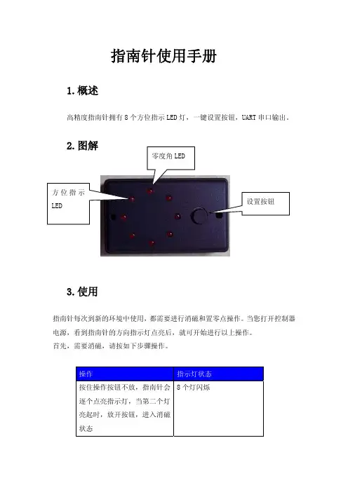
指南针使用手册1.概述高精度指南针拥有8个方位指示LED 灯,一键设置按钮,UART 串口输出。
2.图解3.使用指南针每次到新的环境中使用,都需要进行消磁和置零点操作。
当您打开控制器电源,看到指南针的方向指示灯点亮后,就可开始进行以上操作。
首先,需要消磁,请按如下步骤操作。
操作指示灯状态按住操作按钮不放,指南针会逐个点亮指示灯,当第二个灯亮起时,放开按钮,进入消磁状态8个灯闪烁缓慢旋转指南针或机器人,使8个灯闪烁指南针记忆该场地的磁场环境。
持续三圈以上。
要点:指南针水平,旋转速度要慢。
短按操作按钮,结束消磁 单个指示灯亮,指示方向 设置零点,请按照如下步骤操作:操作 指示灯状态单个指示灯亮,指示方向 将机器人至于场地,并且将指南针水平放置,按钮位于右手边,零度角LED(见图解)对准需要标定的0度位置短按操作按钮,设置0度位置单个指示灯亮,指示0度新的方向4.编程1.流程图2.代码#include"RobotLib.h"int com_1=0;void main(){com_1 = Compass_Degree();}代码中 com_1是自定义的变量,函数 Compass_Degree() 功能为得到指南针的数值,赋值后,com_1的值即为指南针的值。
5.参数参数 数值工作电压 4.5V – 5.5V输出接口 串口波特率 9600数据更新速率 240 次每秒传输速度 4.2毫秒每次分辨率 < 0.5度重复精度 < 1.5度。
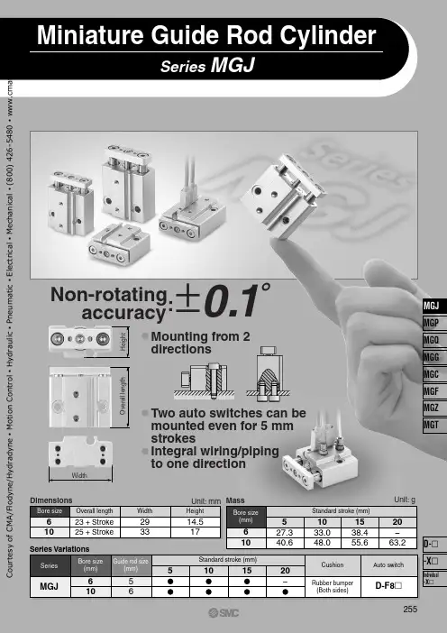
Series MGJMiniature Guide Rod CylinderUnit: mm DimensionsO v e r a l l l e n g t hWidthNon-rotatingaccuracy:H e i g h t±0.1˚Mounting from 2 directionsTwo auto switches can be mounted even for 5 mm strokesIntegral wiring/piping to one direction61023 + Stroke 25 + Stroke293314.517Bore sizeOverall lengthWidthHeight610527.340.61033.048.01538.455.620-63.2Unit: gStandard stroke (mm)MassBore size (mm)565101520-Standard stroke (mm)CushionAuto switchRubber bumper (Both sides)D-F8२Series VariationsGuide rod size(mm)610Bore size (mm)MGJSeries255MGJ MGP MGQ MGG MGC MGFMGZ MGTIndividual -XD- -XC o u r t e s y o f C M A /F l o d y n e /H y d r a d y n e ▪ M o t i o n C o n t r o l ▪ H y d r a u l i c ▪ P n e u m a t i c ▪ E l e c t r i c a l ▪ M e c h a n i c a l ▪ (800) 426-5480 ▪ w w w .c m a f h .c o mHow to OrderMiniature Guide Rod Cylinderø6, ø10Series MGJMGJ Miniature Guide Rod Cylinder610F8NMiniature Guide Rod CylinderBore size 610 6 mm 10 mmNilSCylinder stroke (mm)Refer to the following table q and w .Number of auto switches2 pcs.1 pc.Auto switch typeNilWithout auto switch (Built-in magnet)∗Select the applicable auto switch from the table below.∗The minimum auto switch mounting stroke with 2 auto switches is 4 mm.610Bore size (mm)Standard stroke (mm)5, 10, 155, 10, 15, 20Table q Standard Strokes610ExampleBore size (mm)Applicable stroke (mm)1 to 15 (Spacer type)1 to 20 (Spacer type)Model no.: MGJ6-9Installing a 1 mm width spacer for MGJ6-10External size: same as MGJ6-10Table w Intermediate Stroke (by the 1 mm stroke)∗ Lead wire length symbols:0.5 m (i)(Example) F8N 3 m ................L (Example) F8NL 5 m ................Z (Example) F8NZ∗ Auto switches marked with ć are produced upon receipt of order.∗ When using non-applicable auto switches, please consult with SMC.∗ Auto switch is shipped together (not assembled).TypeSpecial functionElectrical entryIndicator lightWiring (output)Load voltageDCDirect mountingF8NF8P F8B bb b bb b ćććIC circuitRelay PLC–0.5(Nil)3(L)5(Z)Auto switch part no.Lead wire length (m)Applicable loadApplicable Auto Switches/Refer to pages 1719 to 1827 for detailed auto switch specifications.–Yes 24 V5 V 12 V12 V 3-wire (NPN)3-wire (PNP)2-wire Grommet (Perpen-dicular)S o l i d s t a t e s w i t c h256C o u r t e s y o f C M A /F l o d y n e /H y d r a d y n e ▪ M o t i o n C o n t r o l ▪ H y d r a u l i c ▪ P n e u m a t i c ▪ E l e c t r i c a l ▪ M e c h a n i c a l ▪ (800) 426-5480 ▪ w w w .c m a f h .c o mCautionThis product should not be used as a stopper.Series MGJAllowable Eccentric LoadMake sure that the load mass (W) is within the range in the graph below when there is an eccentric distance (L) from the center of the cylinder. Using cylinders are beyond the limit may shorten the product service life or cause damage.WLWL L o a d m a s s (k g )Eccentric distance L (mm)0.010.11100.1110100MGJ10MGJ6Operating pressure 0.3 MPaOperating pressure 0.5 MPa or morePlate Allowable Lateral LoadWhen the eccentric distance (L) generates from the plate (rod end), be sure to keep the load mass (W) no more than a value in the below graphic. Operation outside of this range may cause excessive impact, which may result in the damage to the devices.ConstructionL WLWParts listNo.Description Material Note Body Rod cover Piston Piston rod Magnet retainer Seal retainer Guide rod PlateTorque socket head boltHexagon socket head cap screwBrazier head hexagon socket bolt Bumper Magnet Bushing Rod seal Piston seal O-ring12345678101112131415169Hard anodized Chromated ChromatedChromated, in case of ø6In case of ø10Chromated, in case of ø6In case of ø10Hard chromium electroplatedHard anodized Nickel plated, in case of ø6Nickel plated, in case of ø10Nickel platedAluminum alloy Aluminum alloy Aluminum alloy Stainless steel Aluminum alloy Stainless steel Aluminum alloy Stainless steel Carbon steel Aluminum alloy Carbonl steel Carbon steel Carbon steel Resin —Special friction resistant materialNBR NBR NBRø10100806040200051015205st10st15stL o a d m a s s W (g )Eccentric distance L (mm)ø6300250200150100500051015205st10st15st20stL o a d m a s s W (g )Eccentric distance L (mm)o!0!w i !4!3y ur !1q t !2!5e !1Allowable Kinetic Energy60.0120.05 to 0.50.035Bore size (mm)Operating piston speed (m/s)Allowable kinetic energy (J)10When driving the cylinder with inertial load, keep kinetic energy no more than the allowable value. The area between bold lines in the below graphic shows the relation between load mass and maximum speed.L o a d m a s s (k g )Maximum speed (m/s)ø1010010.011.00.1100.10.01ø6258C o u r t e s y o f C M A /F l o d y n e /H y d r a d y n e ▪ M o t i o n C o n t r o l ▪ H y d r a u l i c ▪ P n e u m a t i c ▪ E l e c t r i c a l ▪ M e c h a n i c a l ▪ (800) 426-5480 ▪ w w w .c m a f h .c o mMiniature Guide Rod Cylinder SeriesMGJDimensionsø6ø10[≅ 6.7]9 + Stroke923 + Stroke8.4ø512ø3ø562920.514.5618.5 + Stroke 3.520.52[≅ 23.3]2820.592 x ø3.3 throughCounterbore ø6.2 depth 0.54 x M3 x 0.5 depth 52 x ø1.2(Guide air release)2 x M3 x 0.5(port size)[Auto switch]2 x M2.5 x 0.45 through6.1 + Stroke[≅ 6.7]ø625 + Stroke 15ø57.5178332310[≅ 24.5]3223115ø623319 + Stroke 8.610.5 + Stroke2 x M3 x 0.5(port size)2 x ø2 through (Guide air release)4 x M4 x 0.7depth 52 x M3 x 0.5 through2 x ø4.3 throughCounterbore ø8 depth 0.55.4 + Stroke[Auto switch]∗ For intermediate strokes other than standard strokes, refer to theManufacture of Intermediate Stroke on page 256.259MGJMGP MGQ MGG MGCMGF MGZMGTIndividual -XD- -XC o u r t e s y o f C M A /F l o d y n e /H y d r a d y n e ▪ M o t i o n C o n t r o l ▪ H y d r a u l i c ▪ P n e u m a t i c ▪ E l e c t r i c a l ▪ M e c h a n i c a l ▪ (800) 426-5480 ▪ w w w .c m a f h .c o mSeries MGJBAAuto Switch Proper Mounting Position (Detection at Stroke End)Bore size Operating rangeø6ø101.61.30.91.734A B (mm)Auto Switch MountingWatchmaker’s screwdriver Auto switch mounting screw•Use a watchmaker’s screwdriver with a handle about 5 to 6 mm in diameter when tightening the auto switch mounting screw.•Tightening torque of auto switch mounting screw should be set 0.10 to 0.20 N .m.260C o u r t e s y o f C M A /F l o d y n e /H y d r a d y n e ▪ M o t i o n C o n t r o l ▪ H y d r a u l i c ▪ P n e u m a t i c ▪ E l e c t r i c a l ▪ M e c h a n i c a l ▪ (800) 426-5480 ▪ w w w .c m a f h .c o mSeries MGJSpecific Product PrecautionsBe sure to read before handling.Refer to front matters 42 and 43 for Safety Instructions and pages 3 to 11 for Actuator and Auto Switch Precautions.w1. Do not put hands or fingers, etc. between the plate and body.Care should be taken that hands or fingers do not get caught in between the cylinder body and the plate when air pressure is applied.Mounting MountingWarningCautionMGJ6MGJ10Bolt ModelM2.5 x 0.45M3 x 0.50.51.0Maximum tightening torque (N·m)3. Flatness of mounting surface should be less than 0.02 mm.When mounting Miniature Guide Rod Cylinder, or mounting plate to work piece, sideling mounting surface may cause malfunction.4. Be sure that the piston rod is extended be-fore mounting loads.If loads are mounted to the plate when the piston rods are retracted, it can lead to distortion of the guides resulting in mal-function.5. When mounting the load with screws, do not exceed the maximum tightening torque.(The torque may vary depending on the mate-rial of the load.)6. When the cylinder output is directly applied to the moving parts of the cylinder, such aswhen clamping a workpiece, be sure to apply the cylinder output to the center of the cylin-der (along the rod axial line).1. Do not scratch or dent the sliding parts of the piston rod and guide rods.Damage to seals can cause air leakage or malfunction, etc.2. When mounting the miniature guide rod cylinder with screws, do not exceed the maximum tightening torque.(The torque may vary depending on the material of the mounting side.)CautionMGJ6MGJ10Bolt Model M3 x 0.5M4 x 0.71.22.70.30.7Top mounting Bottom mounting Maximum tightening torque (N·m)Top mounting Bottom mounting1. This product should not be used as a stopper.OthersCaution261MGJMGP MGQ MGG MGCMGF MGZ MGTIndividual-XD- -XC o u r t e s y o f C M A /F l o d y n e /H y d r a d y n e ▪ M o t i o n C o n t r o l ▪ H y d r a u l i c ▪ P n e u m a t i c ▪ E l e c t r i c a l ▪ M e c h a n i c a l ▪ (800) 426-5480 ▪ w w w .c m a f h .c o m。

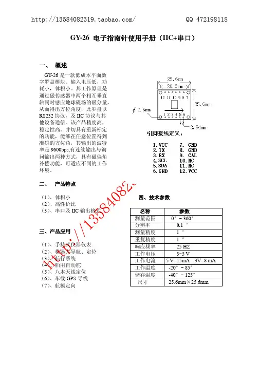
1.测方位角:展开指北针,转动方位框使方位玻璃上的刻度线与方向指标相对正,将平视镜斜放(45°)单眼通过准星瞄向目标,从平视镜反射看到磁针N极所对反字表牌上方位分划,既可读出目标方位角,然后用右手转动方位框使方位玻璃上的刻度线与磁针N极对准,此时方向指标与方位玻璃刻度线所夹之角即为目标方位角(按顺时针方向计算)。
打开指北针,标定好地图(测距时可不标定地图),在图上基准点处插一扎针,转动指北针,使侧尺边切于目标点,即可判读出基准点至目标点的方位角。
2.标定地图:展开指北针,转动方位框,使方位框上的刻度线字与方向指标对准(注意磁偏角的修正),将指北针平放在地图上,准星一端朝向地图北极,使坐标梯尺长与地图磁子午线相切,转动地图使磁针N极对准方位玻璃上的刻度线,此时地图即已标定。
3.求向掩蔽目标行进的行军方向:展开指北针于地图上,使测绘尺经过的图上本人立足点与行军目标,这时方向指标即指应行进的方向。
转动方位框使方位玻璃上的(S、N)方向与地图上的(S、N)方向一致,然后记下方向指标所指方位角读数,面对方向指标拿起指北针旋转身体,使磁针N极与方位玻璃上的刻度线对准,此时通过准星照门向前对准,在此对准线上的各物体(如树林、房屋等)都可作为行军方向的辅助目标,认清辅助目标后即可对之前进。
将指北针关闭装入袋内,但勿转动方位框,到达辅助目标后即可再找一新辅助目标继续前进,直到目的地为止,沿途应经常检查方向读数。
4.已知目标的间隔,估测目标至站立点之间的距离:①通过照门和准星左右两尖端瞄准目标,根据目标的间隔所占准星左右两尖端间宽度的倍数,按10:1的比例公式估算目标的距离。
目标与站立点的距离(米)=目标间隔宽度(米)x10/目标间隔占准星两尖端宽度的倍数例:前方有一公路与我方阵地平行,求公路与阵地的距离。
沿公路有电杆,杆间距离为50米,用距离估定器测得左右两尖端有电杆5根,即每两杆间隔占左右两尖端间距离的1/4倍。


Contact Blocks21AdapterLocating NibOperatorRatingsHazardous Location Class I Division 2 pushbuttons and indicat-ing lights include both the 10250T and E34 corrosion-resistant product lines. The 10250T1H (CBFS) factory-sealed contact blocks have one NO and one NC contact.For use on a flat surface of Type 1, 2, 3, 3S*, 3R, 4, 4X,12 and 13 enclosures.* Applies to indicating lights only.UL Listed and CSA Certified for Class I Division 2Groups B, C, D, and Class I Zone 2, Group IIB + H2.DEVICES10250T/E34 Pushbuttons and Indicating Lights Class I Division 2 Application and Installation InstructionsContact Ratings ............................................. A600, Q300Ingress Protection ..................................................... IP65T emperature Codes per NEC Table 500-5(d) for indicating lights and illuminated operators having a maximum tempera-ture over 100°C:10250T E34Temp. code 201H RB120H T3C 471H SB120H T3C 80H-T3C All selector switches with lamp 120MB T3C 202H RB240H T3A 472HSB240H T3B 81H-T3B All illuminated devices with lamp 1835T4ALENTILLEOperator And Adapter Assembly1. Assemble adapter to operator or light unit and torquemounting screws to 7 – 9.5 lb-in (0.8 – 1.07 Nm).2. Assemble contact block to adapter and torque mountingscrews to 12 – 16 lb-in (1.36 – 1.81 Nm). Contact block mounting location “1” is referenced to the panel locat-ing nib on operator. See illustrations.®IND. CONT. EQ.FOR HAZARDOUS LOCATIONS. A1622Instructional Leaflet P26841Effective July 201410250T/E34 Pushbuttons And Indicating LightsEATON Mounting1. Drill mounting hole for vertical or horizontal mount-ing per the matrix below and diagram to the right.2. Ensure sealing gasket is in place on the operator.Align locating nib on operator with notch in panel and insert through mounting hole. If notched hole is not desired, remove locating nib by placing a flat head screwdriver between nib and operator and prying outward. Note: When using protective boots, see special instruction publication 20437 for place-ment of sealing gasket.3. Place legend plate and mounting nut over operator.Tighten mounting nut securely (5 lb-ft / 6.8 Nm). 4. If applicable, assemble lenses, mushroom buttons,etc. to operator. Tighten selector switch set screw to 8 – 12 lb-in (0.9 – 1.35 Nm). Note: Ensure lens is securely tightened to provide oiltight and watertight seal.For ease of assembly, the following tools are recom-mended: 10250TA95 or E22CW for tighening octagonal nuts. 10250TA74 — lamp removal tool for transformertype light units. E30KV1 — lamp removal tool for full voltage light units.Mounting MatrixPanel Spacing And Drilling DrawingsLegend Dimensions in Inches (mm)Plate A B CDSmall 72.6 (2.87)57.2 (2.25)57.2 (2.25)72.6 (2.87)Jumbo72.6 (2.87)58.6 (2.32)58.6 (2.32)72.6 (2.87)Extra Large72.6 (2.87)65.2 (2.56)64.1 (2.52)72.6 (2.87)10250T/E34 Pushbuttons And Indicating Lights Instructional Leaflet P26841Effective July 2014 EATON Selector Switch Selection And Assembly — Refer T o Contact Block Selection Charts1. Select intended schematic circuit function. Note inyour “cam” column the type of contact (NO or NC), the “1” and “2” circuit locations, and any series orparallel jumper connections that may be required.2. Choose contact blocks that have the requiredschematic circuits and assemble in any convenientsequence that fulfills the “1” and “2” circuit location requirements.3. If applicable, assemble the operator cap.Recommended, set screw tightening torque forselector switches is 8 – 12 lb-in (0.9 – 1.35 Nm).4. The two sections of the operating cam work indepe-ndently. It is important that the contact blocks beoriented with their plungers in the correct “1” and“2” circuit locations. The drawing to the right identi-fies these positions with respect to the locating nib on operator or marked top.5. Assembled operators are factory set for VerticalMounting. For Horizontal Mounting, loosen the setscrew and assemble with the locating nib on the left. otee:N Circuits shown illustrate connections to obtain a selector circuit combination and are shown with their appropriate line dia-grams in BOLD. Field wiring of jumper connections are required as shown.Mounting Location Of Contact Blocks With Respect T o Operator Locating Nib.2-Position Selector SwitchNumber Desired Circuit and Cam Code #1Operator PositionContact Blocks andMounting Location121X O2O X4-Position Selector SwitchNo.Desired Circuit and Operator Position Cam Code #7Contact Blocks andMounting Location12 1X OO O2O X O O3O O X O4O O O X5X O O X6O X X O7O O X X8X X O O9O X O X10X O X ONC NCNO NOororNCNONONCNC (Parallel) NCNO (Parallel) NONO (Parallel) NCNC (Parallel) NONO/NC(Parallel)NO/NC(Parallel)t i u c r i Cn e pO=Ot i u c r i Cd e s o l C=X3-Position Selector SwitchNo.Desired Circuit and Cam Code #2Cam Code #3 Operator PositionContact Blocks and Contact Blocks andMounting Location Mounting Location12121X O O 2X X O 3X O X 4O O X 5O X X 6O X O NO (Series) NC NONC NCNO NO (Parallel) NONO NONC (Parallel) NO NCNC NC (Series) NC3Instructional Leaflet P26841Effective July 201410250T/E34 Pushbuttons And Indicating LightsEaton1000 Eaton Boulevard Cleveland, OH 44122United States © 1999 EatonAll Rights ReservedPublication No. P26841 / 004August 2014Eaton is a registered trademark.All other trademarks are property of their respective owners.ne p O t c a t n o C = O d e s o l C t c a t n o C = XPush-Pull Operators — Contact Block Selection And AssemblyThe illustration to the right assists in the selection of contact blocks. Symbols 1 and 2 show locations of contact circuits after assembly of contact blocks and adapter to the operator. The chart below shows the effects of the push and pull operations on either NO or NC contacts.Grounding Of 10250T And E34 Components General With any electrical component there is the possibility of a loose wire, moisture, etc. causing a short circuit between the component and ground. If the device is adequatelygrounded, the condition causes the protective fuse or circuit breaker to open and remove the potential. If not, an electri-cal hazard may remain unnoticed.Grounding Nibs — 10250TThe 10250T operator is designed to make direct metallic contact to the rear of the panel (with no intervening spacer washers to interfere with component-to-panel ground con-tinuity). As a further aid in establishing an electrical ground, the operator has four metal points (“grounding nibs”)designed to penetrate most paints or other protective coat-ings.Penetration of these nibs is dependent upon the torque applied to the mounting nut. Recommended torque is 5 ft-lbs (6.8 Nm). More or less may be necessary to penetrate the specific type and thickness of your panel coating. Test for continuity to ground after installation. If a short circuit to ground does occur, the fault should be corrected and the device replaced.Earth Ground T erminals — E34These devices are supplied with an integral earth/ground terminal. A 6-32 terminal screw will accommodate ring type terminations for bonding to international specifications.Earth T erminalNibs。

萝卜圈三维机器人教程日期:2012/4/28版本:1.3萝卜圈三维机器人在线仿真平台目录11.1 让我们飞 (1)1.2基本训练任务 (6)1.3体验跑道竞速 (16)1.4金字塔之旅 (18)192.1 迷宫灭火 (19)2.2迷宫灭火回家 (23)2.3 迷宫灭火搜救回家 (30)313.1汽车悬挂系统模拟及前轮转弯 (31)3.2体验极速快感 (40)3.3两轮摩托车的跑法 (42)第四章 3D434.1路线选择和基本跑法 (43)4.2 90度直角转弯——变形金刚? (50)4.3手臂的模拟 (56)585.1三种基本跑法 (58)5.2爬绳索与过吊桥的结合跑法 (61)5.3石板桥与过吊桥的结合跑法 (62)第一章开始机器人的探索之旅第一章开始机器人的探索之旅————初步的构建及编程知识介绍初步的构建及编程知识介绍初步的构建及编程知识介绍同学们,你能想象出吗?在几千米深的大洋底部,机器人在连接或修复海底的电缆;在餐厅里,机器人侍者在为顾客提供优质服务;在医院的手术台前,机器人在为病人做开颅手术……这些并非科学幻想,它们正在或将要成为现实。
那么,目前世界上机器人技术发展到了什么样的水平,又在哪些领域得到了应用?现在,让我们萝卜圈的仿真机器人系统,了解机器人吧。
1.1让我们飞让我们飞很多同学都有自己的飞行梦,现实我们很难自由的构建自己的飞行器,现在我们通过萝卜圈的仿真系统来构建属于自己的飞行器吧!通过本节课的学习,你将能够: 初步掌握机器人构建的基本技巧初步掌握机器人构建的基本技巧。
初步掌握编程的基本方法以及通过任务场景欣赏自己的作品初步掌握编程的基本方法以及通过任务场景欣赏自己的作品。
一、机器人构建构建好之后,保存退出。
文件名:飞。
思考:1、为什么风扇叶左右不会碰撞的话,前后一定也不会碰撞? 2、飞行器的构建首先要注意什么问题? 3、为什么要反转电机?程序编写 写好之后,保存退出。
文件名:飞。

手机罗盘使用方法
手机罗盘是一种通过手机应用程序来使用的罗盘工具。
下面是手机罗盘的使用方法:
1. 下载并安装罗盘应用:首先需要在手机应用商店中搜索并下载一个罗盘应用。
常见的罗盘应用包括“罗盘指南针”、“Compass”、“罗盘&指南针”等。
2. 打开应用程序:安装完毕后,点击应用图标打开罗盘应用程序。
3. 校准罗盘:打开应用程序后,应首先校准手机罗盘。
一般情况下,应用程序会提示你如何进行校准。
通常的校准方法是在手机上画几个数字“8”字形状,以调整罗盘的准确度。
4. 确定方向:校准完罗盘后,你可以用手机指向你感兴趣的方向,然后手机罗盘将显示当前方向的角度和方向指示。
5. 使用附加功能:一些手机罗盘应用程序还提供了一些额外的功能,如高度测量、经纬度坐标等。
你可以浏览应用程序的设置菜单,以确定这些功能是否可用以及如何使用它们。
请注意,手机罗盘的准确度可能会受到外部磁场的干扰。
使用手机罗盘时,应尽量避免靠近磁场强烈的物体,如大型电子设备、金属物体等。
另外,由于手机罗
盘使用的是内置的磁感应器,因此在某些手机上可能无法使用罗盘功能。
最后,确保你的手机处于正常工作状态,并且内置磁感应器没有受到损坏或其他问题。
62式指北针使用方法:(一)测定方位1、测定现地东南西北方向(1)打开罗盘仪.使方位指标“△”对准“〇”;(2)转动罗盘仪.待磁针指北端对准“〇”后,此时所指的方向就是北方,在方位玻璃上就可直接读出现地东、南、西、北方向。
2、标定地图方位标定地图方位就是利用罗盘,使地图上的方位和现地方位一致(1)打开仪器,调整度盘座,使方位指标“△”对准本地区的磁偏角度数;(2)以测绘尺与地图上的真子午线或座标纵线(即东、西图廓的内图廓线)相切;(3)转动地图,使磁针北端指向“O’”,则地图上的方位和现地方位完全一致。
3、测定磁方位角A测定图上目标的磁方位角(1)用指北针精确标定地图并保持地图不动;(2)将测绘尺与所在点和目标点的连线相切,调整度盘座,使指标“△”对准“O”刻划线;(3)待磁针静止后,其北端所指度盘座上的刻度即为所在点至目标点的磁方位角数值。
B测定现地目标的磁方位角(1)打开仪器,使方位指标“△”对准“O”并使反光镜与度盘座略成45°;(2)用大拇指穿入提环,平持仪器,由照准经准星向被测地目标瞄准;(3)从反光镜中注视磁针北端所对准度盘座上的分划即为现地目标的磁方位角数值。
(二)测量距离1、用测绘尺直接量算图上距离2、用里程计量读图上距离(l)先将红色指针归“O”;(2)平持仪器、把里程计测轮轻放在起点上,沿所量取的路线向前滚动至终点;(3)根据指针在比例尺上所指的刻线,即可直接读出相应的实地距离。
例如在1:50000地图上由甲点量至乙点,仪器表面上1:50000比例尺指的是14个刻线,则甲乙两点间的实地距离为7公里。
若在1:100000地图上量得14个刻线、则甲乙两地的距离为14公里。
另外,与有相应比例的(如1:25000)或成倍比例(如1:20000及1:500000)的地图也可经换算量读之。
图二位置3、用距离估定器概略测定现地目标的距离。
仪器上距离估定器两尖端的间隔为照准与准星间距离的1/10,利用相似三角形关系就可测定现地目标的距离。
萝卜圈三维在线仿真平台用户手册萝卜圈三维在线仿真平台用户手册1.简介1.1 平台概述1.2 目标用户1.3 使用准备2.登录与注册2.1 注册流程2.2 登录步骤2.3 密码找回3.个人中心3.1 用户信息管理3.2 修改密码3.3 绑定第三方账号4.平台界面介绍4.1 主页4.2 项目管理4.3 模拟仿真4.4 资源库4.5 论坛与社区4.6 帮助与支持5.项目管理5.1 创建项目5.2 项目设置5.3 团队协作5.4 版本控制5.5 项目导入与导出6.模拟仿真功能6.1 模型建模6.2 场景编辑6.3 物理效果模拟 6.4 运动控制6.5 编程与脚本6.6 仿真参数调整6.7 仿真结果分析7.资源库7.1 模型资源7.2 材质与纹理资源 7.3 动画资源7.4 代码示例8.论坛与社区8.1 发帖与回复8.2 社交功能8.3 好友与关注8.4 私信与通知9.帮助与支持9.1 文档与教程9.2 常见问题解答 9.3 在线客服9.4 用户反馈与建议10.附件附件1:使用范例代码附件3:模拟仿真参数设置指南本文档所涉及的法律名词及注释:- 用户:指在萝卜圈三维在线仿真平台注册并登录的个人或组织。
- 平台:指萝卜圈三维在线仿真平台,提供虚拟仿真环境的Web应用程序。
- 项目:用户在平台上创建的用于进行模拟仿真的工程。
- 注册:用户首次在平台上创建账户并提供必要信息的过程。
- 登录:已注册用户通过输入账号和密码,确认自己身份并进入平台系统的过程。
- 模拟仿真:使用虚拟机械臂进行物理场景模拟和仿真的过程。
- 社区:萝卜圈三维在线仿真平台的交流与分享区域,用户可以在此发帖、回帖和交流。
- 客服:负责解答用户问题、提供技术支持的平台工作人员。
指南针使用方法
指南针是一种常用的导航工具,使用方法如下:
1. 找到一个平稳的地方,远离任何可能会干扰指南针读数的物体,如大型金属物体、电子设备等。
2. 将指南针放置在手掌上,并保持水平。
3. 观察指南针上的指针,确保它在罗盘底座内可以自由转动。
4. 转动自己的身体,直到指南针的指针与指南针底座上的指南针保持在同一水平面上。
5. 确保指南针的指针指向北方,这样就可以确定其他方向的指示。
6. 在使用中需要及时调整指南针的指针位置,确保其准确指示方向。
总之,使用指南针需要找到平稳的环境并保持指南针的水平,同时确保指针指向北方,这样就可以正确使用指南针来进行导航。
萝卜圈三维机器人在线仿真软件 V1.0萝卜圈三维机器人在线仿真平台软件用户手册目录1. 运行环境 (1)1.1运行 (1)1.2控制 (1)2. 使用说明 (2)2.2 登录信息 (2)2.2.1登录信息 (2)2.2.1.1登录 (2)2.2.1.2登录离线模式页面 (3)2.2.1.3登陆在线模式页面 (3)2.3 离线模式 (4)2.3.1构建场景 (5)2.3.1.1模型库 (5)2.3.1.2操作功能 (5)2.3.2搭建机器人 (7)2.3.2.1机器人模型库 (7)2.3.2.1搭建机器人 (7)2.3.2.2机器人参数设置 (9)2.3.3编写控制程序 (9)2.3.3.1可视编程模型库 (11)2.3.3.1编写程序操作 (11)2.3.4仿真运行 (13)2.3.5资源管理 (14)2.4在线模式 (16)2.4.1完成在线任务 (17)1. 运行环境1.1 运行硬件:PC机,1G以上CPU,1G及以上内存,128M 3D显卡软件:Windows XP,Windows Vista,Windows 7,Windows Server 2003,Windows Server 2008,.Net Framework v2.0.50727,DirectX9.0c。
1.2 控制本系统采用图形界面,控制方式以鼠标为主,键盘为辅。
2. 使用说明2.2 登录信息本登录基本信息模块含登录、注册、忘记密码3个基本信息子模块。
2.2.1登录信息2.2.1.1登录在程序菜单中运行“IROBOTQ 3D 机器人在线仿真平台”进入登陆界面,登陆界面如下:图2-2-1-1-1 登录信息页面【注】1) 用户登录时填写的用户名和密码及服务器地址其中一项不相符,会提示用户登录失败。
2) 登录时需要填写或选择服务器的IP地址3) 如果用户多次尝试多个密码,或者已经忘记密码,则转到忘记密码页面,取回密码,重新登录。
2.2.1.2登录离线模式页面选择“离线模式”并点击登陆界面<GO>按钮,进入离线模式主界面,如下图所示:图2-2-1-2-1 登录离线模式页面2.2.1.3登陆在线模式页面选择“在线模式”并点击登陆界面“GO”按钮,进入在线模式主界面,如下图所示:图2-2-1-3-1 在线模式主界面2.3 离线模式以离线模式登陆后,主界面包括构建场景、搭建机器人、编写控制程序、资源管理、开始仿真、在线切换、退出6个基本子模块。
望远镜用户指南概览 (5)关于本指南望远镜概观按钮手势最多显示头---(HUD)的工具和手段入门 (17)版本和功能硬件和软件兼容性说明 (17)启用定位服务设置最多望远镜开始标记和跟踪对象 (22)ViewVinder (23)设置颜色设置最多的HUD快速切换HUD的操作模式缩放指南针 (28)校准增强现实和三维罗盘 (29)寻找目标对象设置最多罗盘罗盘定位模式 (32)罗经 (34)开始使用罗经 (34)确定启动轴承 (35)漂移和调整全球定位系统 (37)设置最多的GPS获取GPS数据设置单位查找 (39)概观按钮快速目标标记添加目标管理目标寻找和跟踪在地图上观测地点的目标 (47)跟踪 (48)设置跟踪跟踪指南针寻找目标对象 (51)星 (51)设置的恒星寻找和跟踪由太阳,月亮,宝来和星导航 (52)地图 (53)设置最高的地图平移和滚动缩放RangeVinder (54)测量距离与光RangeVinder (55)六分仪 (55)用六分仪测角三角洲 (55)角计算器 (56)设置最多计算器计算对象的距离 (57)计算对象的尺寸 (57)从六分仪获取角三角洲 (57)获取对象的距离与地图 (58)斜 (59)相机 (59)精度和准确度 (60)提示 (60)测量地图点之间的距离 (60)故障排除 (60) (61)一览关于本指南本指南描述的功能:•望远镜3.3•指挥官指南针3.3•指挥官指南针精简版3.3所有软件的导航产品以上属于望远镜系列。
本指南范围内的所有产品将被简称为望远镜。
PDF及EPUB在我们本手册PDF和EPUB格式可供下载网站-访手册,并同步到您的设备。
望远镜有了望远镜3D增强现实导航和先进的军用规格的指南针,你可以标记,VIND和实时跟踪-多个地点,轴承,太阳,月亮,星星和使用它作为一喜-高科技viewVinder,罗经,光学rangeVinder,视觉六分仪,地图,全球定位系统,角计算器,倾角和变焦相机。
AN5192应用笔记LSM6DSO:始终开启的3D加速度计和3D陀螺仪引言本文档旨在提供ST LSM6DSO iNEMO六轴惯性传感器模块相关的使用信息和应用提示。
LSM6DSO是系统级封装的3D数字加速度计和3D数字陀螺仪,具有数字I²C、SPI和MIPI I3C SM串口标准输出,组合工作在高性能模式下功耗只要0.55 mA。
由于陀螺仪和加速度计均具有超低噪声性能,始终具有低功耗特性,并结合了高传感精度,因此能够为客户提供最佳运动体验。
此外,加速度计具有智能的休眠到唤醒(活动)和返回休眠(不活动)功能,具备先进的节电能力。
该器件具有动态的用户可选择的满量程加速度范围:±2/±4/±8/±16 g,且角速率范围为±125/±250/±500/±1000/±2000 dps。
经过配置,LSM6DSO可利用硬件识别出的自由落体事件、6D方向、单击和双击感应、活动或不活动、唤醒事件,来生成中断信号。
可使用不同连接方式与外部传感器相连,从而实现额外的功能,例如传感器集合(sensor hub)、辅助SPI等。
LSM6DSO可兼容主要操作系统的要求,提供真实、虚拟以及批量模式传感器。
它经过专门设计,可在硬件上实现大幅运动检测、相对倾斜度、计步功能和时间戳,并提供强大的定制功能:可单独设定最多16个嵌入式有限状态机,用于运动检测或手势识别,例如查看、绝对手腕倾斜、摇晃、连续两次摇晃或拿起。
LSM6DSO还嵌入了机器学习内核逻辑,可以识别数据模式与用户定义的类别集是否匹配。
应用的典型示例有跑步、行走和驾车等活动检测。
LSM6DSO集成有一个9Kbyte的智能先进先出(FIFO)缓冲器,支持对有效数据(包括外部传感器、计步器、时间戳和温度数据)进行动态批处理。
LSM6DSO采用小型塑料焊盘网格阵列封装(LGA-14L),可确保在更大的温度范围(-40 °C至+85 °C)内正常工作。