ST178H红外光电传感器模块产品说明书
- 格式:pdf
- 大小:277.25 KB
- 文档页数:9
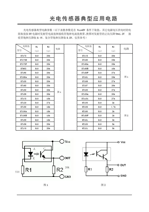
光电传感器典型电路参数(以下表格参数是在Vcc=5V 条件下取值,其它电源电压供电时的电阻取值按5V 电源时发射管电流值和接收管饱和电流值换算,换算时发射管的正向压降V F =1.2V 接收管饱和压降取0.4V,复合管饱和压降取0.8V。
仅供参考)
图1图2
20k
510
A K
E
C
光电传感器典型电路参数(以下表格参数是在Vcc=5V 条件下取值,其它电源电压供电时的电阻取值按5V 电源时发射管电流值和接收管饱和电流值换算,换算时发射管的正向压降V F =1.2V 接收管饱和压降取0.4V,复合管饱和压降取0.8V。
仅供参考)
图3图4
图5
图7
图6 图8
111
光电式传感器的应用(ST188)
1.ST188介绍。
如图所示为ST188的实物图。
A-K为红外发射管。
C_E为红外接收管。
内部电路图为:
2.电器特性:实际
实用时不要超过此值:
流过发光二极管的电流(A_K电流)
反向加在A_K间的电压
最大集射电压
最大射集电压
实用的环境温度
3.光电特性。
4.使用方法。
5.原理说明:
当没有物体反射红外线时,ce 之间截止,无电流流过,输出端直接拉到gnd端,输出低电平。
当有物体反射红外线时, ce 导通了,输出端连接电源。
输出电压为高电平。
电路图就是在第一页所示
510
20K
A
K
E
C。
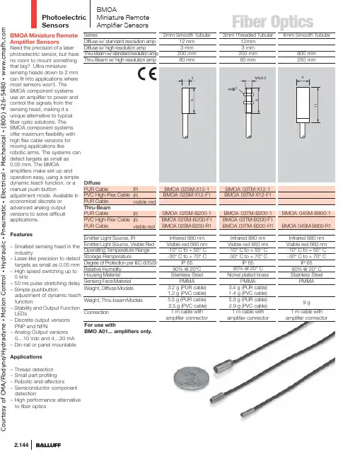
Photoelectric Sensors2.144BMOA Miniature Remote Amplifier SensorsNeed the precision of a laserphotoelectric sensor, but have no room to mount something that big? Ultra miniaturesensing heads down to 2 mmcan fit into applications wheremost sensors won’t. The BMOA component systems use an amplifier to power and control the signals from the sensing head, making it a unique alternative to typical fiber optic solutions. The BMOA component systems offer maximum flexibility with high flex cable versions for moving applications likerobotic arms. The systems can detect targets as small as 0.05 mm. The BMOAamplifiers make set-up and operation easy, using a simpledynamic teach function, or amanual push-button adjustment mode. Available in economical discrete or advanced analog outputversions to solve difficult applications.Features– Smallest sensing head in the industry– Laser-like precision to detect targets as small as 0.05 mm – High speed switching up to 5 kHz– 50 ms pulse stretching delay – Simple pushbuttonadjustment of dynamic teach function– Stability and Output Function LEDs– Discrete output versions PNP and NPN– Analog Output versions 0…10 Vdc and 4…20 mA – Din-rail or panel mountable Applications– Thread detection – Small part profiling – Robotic end-effectors– Semiconductor component detection– High performance alternative to fiber opticsBMOAMiniature Remote Amplifier SensorsBMO A01... amplifiers only.C o u r t e s y o f C M A /F l o d y n e /H y d r a d y n e ▪ M o t i o n C o n t r o l ▪ H y d r a u l i c ▪ P n e u m a t i c ▪ E l e c t r i c a l ▪ M e c h a n i c a l ▪ (800) 426-5480 ▪ w w w .c m a f h .c o m2.145t p76o amplifier connectoramplifier connectoramplifier connectorC o u r t e s y o f C M A /F l o d y n e /H y d r a d y n e ▪ M o t i o n C o n t r o l ▪ H y d r a u l i c ▪ P n e u m a t i c ▪ E l e c t r i c a l ▪ M e c h a n i c a l ▪ (800) 426-5480 ▪ w w w .c m a f h .c o mPhotoelectric Sensors2.146High SpeedBMO A01-I-PU-C-02BMO A01-I-NU-C-02SeriesDiscrete Output PNP Normally-open NPNNormally-open Analog Output 0...10 Vdc 4...20 mASupply VoltageVoltage Drop U d at I e Output Current (digital)Analog Output Type (Voltage)Analog Output Type (Current)Analog Output Load (voltage) min load Analog Output Load (current) Max Load Current Consumption I o (no load)Protections Response TimeSwitching FrequencyPulsed/Non-Pulsed Light Source Output FunctionOperating Temperature Range Degree of Protection per IEC 60529Sensitivity/Range Adjustment Power/Stability Indication Alarm Indication Output LEDHousing MaterialWeightConnection (to control system)10…30 Vdc< 2 V 100 mA 45 mAShort Circuit, Reverse Polarity100 µs 5 KHz Non-PulsedLight/Dark Selectable -10° C to +55° CIP 65Teach-in and ManualGreen LED Yellow LED ABS 55 g2 m PVC Cable ,3 x 26 AWGq w e rBMOAMiniature Remote Amplifier SensorsSensitivity settingAUT – the amplifier will determine the best setting for the application.MAN – this allows you to fine-tune the settings or manually adjust the sensor for difficult applications.Wiring DiagramsOutput GNDOutput GNDrC o u r t e s y o f C M A /F l o d y n e /H y d r a d y n e ▪ M o t i o n C o n t r o l ▪ H y d r a u l i c ▪ P n e u m a t i c ▪ E l e c t r i c a l ▪ M e c h a n i c a l ▪ (800) 426-5480 ▪ w w w .c m a f h .c o mFiber Optics/photoelectricObject Resolution for Diffuse Sensors42-2-4-6-8Y(mm)055M, 06TM & 66RMYMeasuring Arrangement:900a standard resolution amplifier.04SM, 05TM & 66RMthe beam at certain ranges.Sensing Distance for Diffuse Sensors0.8% 1.6% 3.1% 6.3% 12.5% 25% 50% 100%Absolute Mode (ABS)This mode offers the maximum accuracy for allapplications. The amplifier will offer 8 stages ofCourtesyofCMA/Flodyne/Hydradyne▪MotionControl▪Hydraulic▪Pneumatic▪Electrical▪Mechanical▪(8)426-548▪www.cmafh.co m。
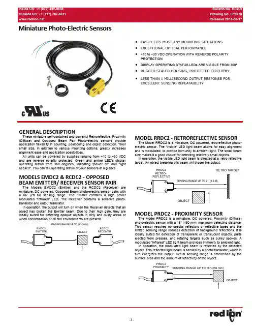
MiniaturePhoto ‐Electric Sensors•EASILY FITS MOST ANY MOUNTING SITUATIONS •EXCEPTIONAL OPTICAL PERFORMANCE•+10 to +30 VDC OPERATION WITH REVERSE POLARITY PROTECTION•DISPLAY OPERATING STATUS LEDs ARE VISIBLE FROM 360°•RUGGED SEALED HOUSING, PROTECTED CIRCUI TRY •LESS THAN 1 MILLISECOND OUTPUT RESPONSE FOR EXCELLENT SENSING REPEATABILITYGENERAL DESCRIPTIONThese miniature self-contained and powerful Retroreflective, Proximity (Diffuse) and Opposed Beam Pair Photo-electric sensors provide application flexibility in counting, positioning and object detection. Their small size, in addition to various mounting options, greatly increases alignment ease and application possibilities.All units can be powered by supplies ranging from +10 to +30 VDC and are reverse polarity protected. Green and amber LED’s display operating status from 360 degrees, indicating “power on” and “light sensed”. You can tell operating status of your sensors at a glance.MODELS EMDC2 & RCDC2 ‐ OPPOSED BEAM EMITTER/ RECEIVER SENSOR PAIRThe Models EMDC2 (Emitter) and the RCDC2 (Receiver) are miniature, DC powered, Opposed Beam photo-electric sensor pairs with a 66’ (20 M) sensing range. The Emitter contains a high power modulated “infrared” LED. The Receiver contains a sensitive photo-transistor and output transistor.In operation, the output will turn on when the Receiver detects that an object has broken the Emitter beam. Due to their high gain, they are ideally suited for detecting opaque objects in dirty and dusty areas or when condensation or oil film environments are present.MODEL RRDC2 ‐ RETROREFLECTIVE SENSORThe Model RRDC2 is a miniature, DC powered, retroreflective photo-electric sensor. The “visible” LED light beam allows for easy alignment and is modulated, to provide immunity to ambient light. The small beam size makes it a good choice for detecting relatively small objects.In operation, the visible LED light beam is directed at a retro reflective target. An object breaking this beam will trigger the output.MODEL PRDC2 ‐ PROXIMITY SENSORThe Model PRDC2 is a miniature, DC powered, Proximity (Diffuse)photo-electric sensor with a 18" (450 mm) maximum detecting distance.This sensor requires no special reflectors or reflective tapes and the limited sensing range reduces detection of background reflections. It is ideally suited for detection of transparent or translucent objects, parts ejected from presses, and rotating targets such as pulley spokes. A modulated “infrared” LED light beam provides immunity to ambient light.In operation, the modulated light beam is reflected by the detected object. This reflected light beam is sensed by a photo-transistor, which in turn energizes the output. Actual sensing range is determined by the surface area and the amount of reflectivity of the object.SAFETY SUMMARYAll safety related regulations, local codes and instructions that appear in this literature or on equipment must be observed to ensure personal safety and to prevent damage to either the instrument or equipment connected to it. If equipment is used in a manner not specified by the manufacturer, the protection provided by the equipment may be impaired.Do not use this unit to directly command motors, valves, or other actuators not equipped with safeguards. To do so can be potentially harmful to persons or equipment in the event of a fault to the unit. An independent and redundant temperature limit indicator with alarm outputs is strongly recommended.SPECIFICATIONS1.SUPPLY VOLTAGE: 10 to 30 VDC (10% maximum ripple) at less than25 mA, exclusive of loadProtected against reverse polarity and transient voltages2.LIGHT SOURCE:Opposed and Diffuse mode models: Infrared, 940 nmRetroreflective mode models: Visible red, 660 nm3.ADJUSTMENTS:Diffuse, and Retroreflective mode models: Single-turn sensitivity (Gain) adjustment potentiometer4.INDICATORS:2 LED indicators on sensor top:Green solid: Power onAmber solid: Light sensedGreen flashing: Output overloadedAmber flashing: Marginal excess gain (1 to 1.5x excess gain)5.REQUIRED OVERCURRENT PROTECTION:application per the supplied table.Overcurrent protection may be provided with external fusing or via Current Limiting, Class 2 Power Supply.Supply wiring leads < 24 AWG shall not be spliced.6.REPEATABILITY:Opposed Mode: 100 microsecondsDifuse and Retroreflective Mode: 150 microseconds7.OUTPUT CONFIGURATION:Solid-state NPN (current sinking)Rating: 100 mA maximum at 25°COff-state Leakage Current: less than 50 μA @ 30 VDCON-state Saturation Voltage: less than 1 V @ 10 mA; less than 1.5 V @ 100 mAProtected against false pulse on power-up and continuous overload or short circuit of output8.OUTPUT RESPONSE:Opposed Mode: 750 microseconds ON; 375 microseconds OFFDifuse and Retroreflective Mode: 600 microseconds ON/OFFNote: 100 millisecond delay on power-up; output does not conduct during this time9.CONSTRUCTION:ABS housing3 mm mounting hardware included10.CONNECTIONS: 2 m (6.5 ft) 4-wire PVC cable.11.ENVIRONMENTAL:IEC IP67; NEMA 612.OPERATING CONDITIONS:Temperature: –4°F to 158°F (–20°C to 70°C)Relative Humidity: 90% @ 50°C (non-condensing)13.CERTIFICATIONS:UL Recognized Component(Banner Engineering QPS186 Series File #E71083)14.WEIGHT: 2.0 oz (62.2 g)SUPPLYWIRINGREQUIRED OVERCURRENTPROTECTION20 5.0 A22 3.0 A24 2.0 A26 1.0 A280.8 A300.5 AWIRINGRCDC2, RRDC2, & PRDC2EMDC2PERFORMANCE CURVESOpposed ModeRetroflective ModeDiffuse Mode(Performance is based on a 90% reflectance white test card.)SET‐UP AND INSTALLATIONUSING THE PHOTOELECTRICLED INDICATORSThe photoelectric has two bright LEDs; both are visible from 360 degrees. They indicate the following:The unit features an extremely simplemethod for setting sensitivity (gain). Reducegain by turning the pot counter-clockwise. If thegain is set too low, turn the pot clockwise to theappropriate level. Gain may be readjusted inthis way at any time.BRACKET DIMENSIONS InMBMAB200MBMSB200Green solid:Power onAmber solid:Light sensedGreen flashing:Output overloadedAmber flashing:Marginal excess gain (1 to 1.5x excess gain)ORDERING INFORMATIONEMDC2DC Emitter (Opposed Beam Pair)EMDC2000 RCDC2DC Receiver (Opposed Beam Pair)RCDC2000 RRDC2Retroreflective DC Photo-Electric Sensor RRDC2000 PRDC2Proximity (Diffuse) DC Photo-Electric Sensor PRDC2000 MBMA Right-Angle Mounting Bracket MBMAB200 MBMS Side-Mount Mounting Bracket MBMSB200RT 1.5'' Reflective Target RT100000 3'' Reflective Target RT200000RRTAPE50 mm x 2.5 m Reflective Tape RRTAPE00LIMITED WARRANTY(a) Red Lion Controls Inc., (the “Company”) warrants that all Products shall be free from defects in material andworkmanship under normal use for the period of time provided in “Statement of Warranty Periods” (available at) current at the time of shipment of the Products (the “Warranty Period”). EXCEPT FOR THE ABOVE-STATED WARRANTY, COMPANY MAKES NO WARRANTY WHATSOEVER WITH RESPECT TO THEPRODUCTS, INCLUDING ANY (A) WARRANTY OF MERCHANTABILITY; (B) WARRANTY OF FITNESS FOR APARTICULAR PURPOSE; OR (C) WARRANTY AGAINST INFRINGEMENT OF INTELLECTUAL PROPERTYRIGHTS OF A THIRD PARTY; WHETHER EXPRESS OR IMPLIED BY LAW, COURSE OF DEALING, COURSE OFPERFORMANCE, USAGE OF TRADE OR OTHERWISE. Customer shall be responsible for determining that aProduct is suitable for Customer’s use and that such use complies with any applicable local, state or federal law.(b) The Company shall not be liable for a breach of the warranty set forth in paragraph (a) if (i) the defect is a resultof Customer’s failure to store, install, commission or maintain the Product according to specifications; (ii) Customeralters or repairs such Product without the prior written consent of Company.(c) Subject to paragraph (b), with respect to any such Product during the Warranty Period, Company shall, in itssole discretion, either (i) repair or replace the Product; or (ii) credit or refund the price of Product provided that, ifCompany so requests, Customer shall, at Company’s expense, return such Product to Company.(d) THE REMEDIES SET FORTH IN PARAGRAPH (c) SHALL BE THE CUSTOMER’S SOLE AND EXCLUSIVEREMEDY AND COMPANY’S ENTIRE LIABILITY FOR ANY BREACH OF THE LIMITED WARRANTY SET FORTHIN PARAGRAPH (a).。
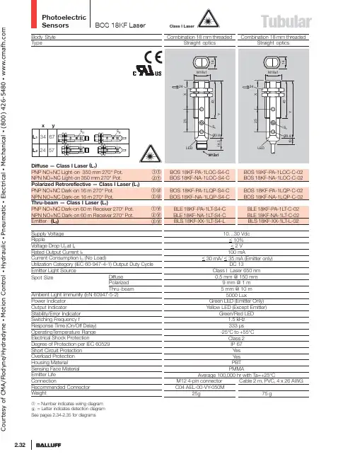
Photoelectric SensorsTubular2.32Body Style TypeDiffuse — Class I Laser (L 1)PNP NO+NC Light-on 350 mm 270° Pot.NPN NO+NC Light-on 350 mm 270° Pot.Polarized Retroreflective — Class I Laser (L 1)PNP NO+NC Dark-on 16 m 270° Pot.NPN NO+NC Dark-on 16 m 270° Pot.Thru-beam — Class I Laser (L 1)PNP NO+NC Dark-on 60 m Receiver 270° Pot.NPN NO+NC Dark-on 60 m Receiver 270° Pot.Emitter (L 2)Supply Voltage RippleVoltage Drop U d at I eRated Output Current I eCurrent Consumption I O (No Load)Utilization Category (IEC 60-947-4-1) Output Duty Cycle Emitter Light SourceSpot SizeAmbient Light Immunity (EN 60947-5-2)Power Indicator Output IndicatorStability/Error Indicator Switching Frequency fResponse Time (On/Off Delay)OperatingT emperature Range Electrical Shock ProtectionDegree of Protection per IEC 60529Short Circuit Protection Overload Protection Housing MaterialSensing Face Material Emitter Life ConnectionRecommended ConnectorWeightBOS 18KF LaserCombination 18 mm threadedStraight optics BOS 18KF-PA-1LOC-S4-C BOS 18KF-NA-1LOC-S4-C BOS 18KF-PA-1LQP-S4-C BOS 18KF-NA-1LQP-S4-C BLE 18KF-PA-1LT -S4-C BLE 18KF-NA-1L T -S4-C BLS 18KF-XX-1LT -S4-LCombination 18 mm threadedStraight opticsBOS 18KF-PA-1LOC-C-02BOS 18KF-NA-1LOC-C-02BOS 18KF-PA-1LQP-C-02BOS 18KF-NA-1LQP-C-02BLE 18KF-PA-1LT -C-02BLE 18KF-NA-1LT -C-02BLS 18KF-XX-1LT -L-0210…30 Vdc < 10%< 2 V 100 mA< 30 mA/ < 35 mA (Emitter only)DC 13Class I Laser 650 nm 0.5 mm @ 150 mm 9 mm @ 1 m 5 mm @ 10 m 5000 LuxGreen LED (Emitter Only)Yellow LED (Except Emitter)Green/Red LED1.5 kHz 333 µs -25°C to +55°CClass 2IP 67Yes Yes PBT PMMAAverage 100,000 hr with Ta=+25°CM12 4-pin connector Cable 2 m, PVC, 4 x 26 AWGDiffuse Polarized Thru-beamqT wT qU wU qV wV eVq = Number indicates wiring diagram A = Letter indicates detection diagram See pages 2.34-2.35 for diagramsClass I LaserC o u r t e s y o f C M A /F l o d y n e /H y d r a d y n e ▪ M o t i o n C o n t r o l ▪ H y d r a u l i c ▪ P n e u m a t i c ▪ E l e c t r i c a l ▪ M e c h a n i c a l ▪ (800) 426-5480 ▪ w w w .c m a f h .c o mTubularClass I Laser Body StyleTypeDiffuse — Class I Laser (L1)PNP NO+NC Light-on 250 mm 270° Pot.NPN NO+NC Light-on 250 mm 270° Pot.Polarized Retroreflective — Class I Laser (L1)PNP NO+NC Dark-on 9 m 270° Pot.NPN NO+NC Dark-on 9 m 270° Pot.Thru-beam — Class I Laser (L1)PNP NO+NC Dark-on 50 m Receiver 270° Pot.NPN NO+NC Dark-on 50 m Receiver 270° Pot.Emitter (L2)Supply VoltageRippleVoltage Drop U d at I eRated Output Current I eCurrent Consumption I O (No Load)Utilization Category (IEC 60-947-4-1) Output Duty Cycle Emitter Light SourceSpot SizeAmbient Light Immunity (EN 60947-5-2)Power IndicatorOutput IndicatorStability/Error IndicatorSwitching Frequency fResponse Time (On/Off Delay)Operating T emperature RangeElectrical Shock ProtectionDegree of Protection per IEC 60529Short Circuit ProtectionOverload ProtectionHousing MaterialSensing Face MaterialEmitter LifeConnectionRecommended ConnectorWeightDiffusePolarizedThru-beamqWwWqXwXqYwYeYq = Number indicates wiring diagramA = Letter indicates detection diagramSee pages 2.34-2.35 for diagramsCourtesyofCMA/Flodyne/Hydradyne▪MotionControl▪Hydraulic▪Pneumatic▪Electrical▪Mechanical▪(8)426-548▪www.cmafh.co mPhotoelectric SensorsTubular2.34BOS 18KF/KWTechnical DataTolerance with standard setting Tolerance with fine settingA B C Foreground/Background Suppression – straightMid Range Diffuse – straightD EFBN BK WH BU+U 0 VTest+Test–Wiring DiagramsFixed Focus – straightNon-Polarized Retroreflective – straightH Transparent Retroreflective – straight Thru-Beam – straightI J qPAwNAeXXK Background Suppression – 90°405060708090100110120100806040200B ac kg r ou nd s up pr es s io n a r e a F o re g r ou n ds u pp r es si o na r e aD e t e c t i o n a r e a 01020304050151050-5-10-15cm mm 01020304050100101Gray 18%White 90%cmWhite 90%Gray 18%0246810126420-2-4-6cm Gray 18%White 90%mm24681012100101mcm White 90%Gray 18%G Polarized Retroreflective – straight531-1-2-3m101m3210cmm C o u r t e s y o f C M A /F l o d y n e /H y d r a d y n e ▪ M o t i o n C o n t r o l ▪ H y d r a u l i c ▪ P n e u m a t i c ▪ E l e c t r i c a l ▪ M e c h a n i c a l ▪ (800) 426-5480 ▪ w w w .c m a f h .c o m。
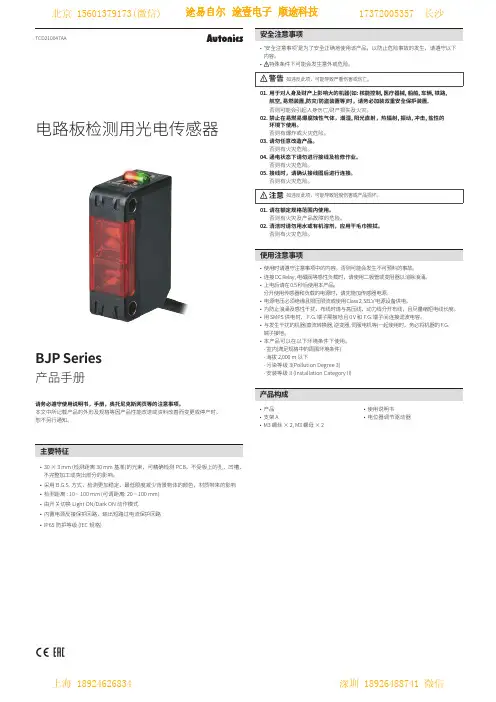
TCD210047AA电路板检测用光电传感器BJP Series产品手册请务必遵守使用说明书,手册,奥托尼克斯网页等的注意事项。
本文中所记载产品的外形及规格等因产品性能改进或资料改善而变更或停产时,恕不另行通知。
ᜢᜫ不完整加工或突出部分的影响。
• 采用 B .G.S. 方式,检测更加稳定,最低限度减少背景物体的颜色,材质带来的影响• 检测距离 : 10 ~ 100 mm (可调距离: 20 ~ 100 mm)• 由开关切换 Light ON/Dark ON 动作模式• 内置电源反接保护回路,输出短路过电流保护回路•IP65 防护等级 (IEC 规格)• 支架 A• M3 螺丝 × 2, M3 螺母 × 2•电位器调节驱动器内容。
• 特殊条件下可能会发生意外或危险。
警告 如违反此项,可能导致严重伤害或伤亡。
01. 用于对人身及财产上影响大的机器(如: 核能控制, 医疗器械, 船舶, 车辆, 铁路,航空, 易燃装置,防灾/防盗装置等)时,请务必加装双重安全保护装置。
否则可能会引起人身伤亡,财产损失及火灾。
02. 禁止在易燃易爆腐蚀性气体,潮湿, 阳光直射,热辐射, 振动, 冲击, 盐性的环境下使用。
否则有爆炸或火灾危险。
03. 请勿任意改造产品。
否则有火灾危险。
04. 通电状态下请勿进行接线及检修作业。
否则有火灾危险。
05. 接线时,请确认接线图后进行连接。
否则有火灾危险。
注意 如违反此项,可能导致轻度伤害或产品损坏。
01. 请在额定规格范围内使用。
否则有火灾及产品故障的危险。
02. 清洁时请勿用水或有机溶剂,应用干毛巾擦拭。
否则有火灾危险。
• 连接 DC Rel a y , 电磁阀等感性负载时,请使用二极管或变阻器以消除浪涌。
• 上电后请在 0.5 秒后使用本产品。
分开使用传感器和负载的电源时,请先施加传感器电源。
• 电源电压必须绝缘且限压限流或使用 Cl ass 2, S EL V 电源设备供电。
硫化铅(PbS)红外光电传感器(型号:RGF-L1212)使用说明书版本号:1.0实施日期:2021-02郑州炜盛电子科技有限公司ZhengzhouWinsenElectronicTechnologyCo.,Ltd声明本说明书版权属郑州炜盛电子科技有限公司(以下称本公司)所有,未经书面许可,本说明书任何部分不得复制、翻译、存储于数据库或检索系统内,也不可以电子、翻拍、录音等任何手段进行传播。
感谢您使用炜盛科技的系列产品。
为使您更好地使用本公司产品,减少因使用不当造成的产品故障,使用前请务必仔细阅读本说明书并按照所建议的使用方法进行使用。
如果用户不依照本说明书使用或擅自去除、拆解、更换传感器内部组件,本公司不承担由此造成的任何损失。
您所购买产品的颜色、款式及尺寸以实物为准。
本公司秉承科技进步的理念,不断致力于产品改进和技术创新。
因此,本公司保留任何产品改进而不预先通知的权力。
使用本说明书时,请确认其属于有效版本。
同时,本公司鼓励使用者根据其使用情况,探讨本产品更优化的使用方法。
请妥善保管本说明书,以便在您日后需要时能及时查阅并获得帮助。
郑州炜盛电子科技有限公司硫化铅(PbS)红外光电传感器◆产品描述:非制冷型硫化铅(PbS)传感器是一种铅盐类红外光电传感器,其工作原理是基于半导体材料的光电导效应,从而将红外辐射能量转换为电信号。
PbS传感器主要响应波长为短波红外(1.0~3.0μm),广泛应用于火焰及高温探测。
图1:传感器实物图(蓝宝石)◆传感器特点:TO-5封装;非制冷;响应快;探测率高;◆主要应用:⏹适用于易燃易爆场合的火焰监测;⏹火花、火星、闪爆点探测;⏹高温工业炉温度探测;⏹光谱分析;◆技术指标:表1:技术指标性能数值单位光敏面积2*2 mm响应波长范围1~3 μm峰值波长 2.7 μm响应时间200 μs峰值响应度4*105 V/W峰值归一化探测率1*1011 cm·Hz½/W暗电阻0.3~3 MΩ工作温度-30~60 ℃◆传感器封装尺寸TO-5(单位:mm):图2:传感器封装尺寸管脚①②③定义探测探测GND ◆传感器典型电路:图3:典型应用电路传感器特性:图4:传感器特征光谱响应曲线图5:不同调制频率对传感器性能影响曲线图6:不同温度对传感器暗电阻影响曲线◆常用传感器类型:表2:常用传感器类型传感器型号RGF-L1212H RGF-L1212A RGF-L1212B 窗口类型蓝宝石窄带滤光片中心波长(um)1~6 1.05 2.7半高宽(nm)/ 60 300透光率(%)>90% >90% >90%备注通用型参比波段探测波段◆使用注意事项:⏹使用过程中需要一个偏置电压才能工作,传感器响应信号随偏压增大线性增大,但偏压不宜不过高,一般为50V/mm;⏹负载电阻应与传感器阻值匹配,才能获得最佳的输出;⏹使用中应避免传感器频繁、过度振动,强烈冲击或碰撞,以免传感器引线脱落;⏹使用中避免手指接触传感器窗口,以免污染窗口降低使用寿命;⏹传感器安装时,焊接时间不宜超过5秒,防止过热影响传感器性能。

规格(注1):(注2):(注3):(注4):如果串联连接5~8个放大器为50mA ,如果串联连接9~16个放大器为25mA 。
连接器型LS-401(P )没有装备外部输入。
H-SP 模式改变为其他模式后,当使用防干扰功能、收集的数据库载入/保存功能或复制功能时,再打开电源。
连接器型LS-401(P )不附带电缆。
请按下述使用另售单触电缆 。
母电缆(4芯):CN-74-C1(电缆长1m ),CN-74-C2(电缆长2m ),CN-74-C5(电缆长5m )子电缆(2芯):CN-72-C1(电缆长1m ),CN-72-C2(电缆长2m ),CN-72-C5(电缆长5m )注意事项●●●●●●●●●●●●●●●●请确认在电源关闭状态下进行接线和增设作业。
请确认电源电压在额定范围内变化。
请注意如果使用的电压超出额定范围,或直接连接AC电源,传感器可能烧坏或损坏。
如果在该传感器附近使用产生噪音的设备(开关调节器,转换发动机等),请将设备机架接地端子(F.G.)接地。
由于超长距离(U-LG)模式的灵敏度比其他模式更高,所以更容易受外部噪音影响。
确保使用前检查周围环境。
如果电源是市场上零售的开关调节器,请务必安装电源的机架接地端子(F.G.)接地。
电源接通后短时间(约0.5秒)内,请勿使用。
请注意短路或负荷的错误接线可能烧坏或损坏传感器。
请勿将电线与高压线或电源线一起或在同一管内拉线,这可能会由于感应而引起故障。
连接器型LS-401(P )必须使用另售单触电缆。
0.3mm 2以上电缆可延长至100m。
但为减少噪音,使接线尽可能短。
请勿用在屋外。
避免灰尘、污垢和水蒸气。
请勿将传感器与水、油、油脂或有机溶液,如稀释剂等直接接触。
此传感器不可在有易燃易爆气体的环境下使用。
不可拆卸或改装传感器。
MC-LS400 No.8137-00非常感谢您购买SUNX产品。
请仔细、完整阅读此使用说明书以便正确、合理地使用此产品。
请务必妥善保管此说明书。

电动小车最终方案版(总28页)--本页仅作为文档封面,使用时请直接删除即可----内页可以根据需求调整合适字体及大小--一、任务设计并制作一个简易智能电动车,其行驶路线示意图如下:二、要求1、基本要求(1)电动车从起跑线出发(车体不得超过起跑线),沿引导线到达B 点。
在“直道区”铺设的白纸下沿引导线埋有1~3块宽度为15cm、长度不等的薄铁片。
电动车检测到薄铁片时需立即发出声光指示信息,并实时存储、显示在“直道区”检测到的薄铁片数目。
(2)电动车到达B点以后进入“弯道区”,沿圆弧引导线到达C点(也可脱离圆弧引导线到达C点)。
C点下埋有边长为15cm的正方形薄铁片,要求电动车到达C点检测到薄铁片后在C点处停车5秒,停车期间发出断续的声光信息。
(3)电动车在光源的引导下,通过障碍区进入停车区并到达车库。
电动车必须在两个障碍物之间通过且不得与其接触。
(4)电动车完成上述任务后应立即停车,但全程行驶时间不能大于90秒,行驶时间达到90秒时必须立即自动停车。
2、发挥部分(1)电动车在“直道区”行驶过程中,存储并显示每个薄铁片(中心线)至起跑线间的距离。
(2)电动车进入停车区域后,能进一步准确驶入车库中,要求电动车的车身完全进入车库。
(3)停车后,能准确显示电动车全程行驶时间。
(4)其它。
三、评分标准比较、设计与论证,理论分析与计算,电路图及有关设计文件,测试方法与仪器,测试数据及测试结果分析实际完成情况50发挥部分完成第(1)项15 完成第(2)项17 完成第(3)项8 其它10四、说明1、跑道上面铺设白纸,薄铁片置于纸下,铁片厚度为~。
2、跑道边线宽度5cm,引导线宽度2cm,可以涂墨或粘黑色胶带。
示意图中的虚线和尺寸标注线不要绘制在白纸上。
3、障碍物1、2可由包有白纸的砖组成,其长、宽、高约为50cm12cm6cm,两个障碍物分别放置在障碍区两侧的任意位置。
4、电动车允许用玩具车改装,但不能由人工遥控,其外围尺寸(含车体上附加装置)的限制为:长度≤35cm,宽度≤15cm。

智能小车的循迹避障行驶目录摘要 (III)Abstract (IV)第一章绪论 (1)1.1 课题背景 (1)1.2 研究目的及意义 (1)1.3 本设计完成的工作 (2)第二章总体设计方案 (3)2.1 方案选择及论证 (4)4446662.2 最终方案 (7)第三章硬件设计 (8)3.1 主控器STC89C52 (8)3.2 单片机复位电路设计 (10)3.3 单片机时钟电路设计 (10)3.4 避障模块 (10)3.5 电源设计 (11)3.6 电机驱动模块 (12)3.7 红外循迹模块 (13)3.8 小车车体总体设计 (15)第四章软件设计 (16)4.1 主程序流程图 (16)第五章系统的安装与调试 (18)5.1 系统的安装 (18)5.2 电路的调试 (19) (20)205.3 测试结果与分析 (20)结论 (21)参考文献 (22)致谢........................................................ 错误!未定义书签。
附录1 整机电路原理图.. (22)附录2 部分源程序 (23)智能小车的循迹避障行驶摘要在现代化的生产生活中,智能机器人已经渐渐普及到国防、工业、交通、生活等各个领域。
为了使生产更加有效率更加安全,使生活更加方便、轻松,智能机器人起到了越来越重要的作用。
智能小车属于智能机器人的一种,同样能给生产生活带来极大的便利。
它能够自己判断路面情况,并将各种信息反馈给单片机。
所用到的学科有自动控制原理、传感器技术、计算机和信息技术等多门学科。
智能车能够在一定程度上解放人的双手、减小工作强度从而改善人们的生活,提高生产的质量和效率。
能够自动循迹和避绕障碍物行驶则是智能小车需要的最基本的功能。
小车之所以能够自动避开障碍物并进行循迹是因为它可以感测引导线和行进路上的障碍物,因此这里采用超声波测距模块和红外传感器来实现这些功能。
本文先介绍了选题的背景及发展前景,描述了智能车在生产和生活中发展和应用的情况;接着对硬件部分所用器件的原理和特点进行了介绍;然后对软件设计和机械部分进行说明;在文章的最后就整个过程的体会及智能机器人的发展进行了总结和展望。
单光束反射取样式光电传感器:ST178一、特点1.采用高发射功率红外光电二极管和高灵敏度光电晶体管组成。
2.检测距离可调整范围大,4-10mm可用。
3.采用非接触检测方式。
二、应用范围1.IC卡电度表脉冲数据采样。
2.集中抄表系统数据采集。
3.水表数据采集。
4.传真机、碎纸机等办公设备。
5.与本公司的方向判别电路ST288A结合使用可判别被测物的运动方向及正反转速测量、行程测量等。
三、极限参数(Ta=25℃)项目符号数值单位输入正向电流IF50mA 反向电压Vr6V耗散功率P75mW输出集-射电压V ceo25V 射-集电压V eco6V集电极功耗Pc50mW工作温度T opr-20∽65℃储存温度T stg-30∽75℃www.hsdz369.cn四、光电特性(Ta=25℃)注:集电极亮电流IL 、饱和压降V CE 、响应时间是在红外光电传感器前端面与亮检测面距离8mm +-3mm 处测得,其数值受亮检测面的表面光洁度及平整度影响。
项目符号测试条件最小典型最大单位输入正向压降V F I F =20mA - 1.25 1.5V 反向电流I R V R =3V --10μA 输出集电极暗电流I ceo Vce=20V--1μA 集电极亮电流ILVce=15VI F =8mAH10.30--mA H20.40--mA H30.50--mA 饱和压降V CE I F =8mA Ic=0.5mA--0.4V 传输特性响应时间TrI F =20mA Vce=10VIRc=100Ω-5-μs Tf-5-μsw ww .h s d z 369.c n。
1800 人体红外感应器SA-180-WM-P1非常感谢您购买“欧瑞仕”产品。
为了使您顺利使用该产品,请认真阅读本使用说明书正确使用该产品,安装此产品需要有一定的电子安装操作经验。
如对安装过程有任何疑问之处,请向持有资格证书的电工咨询。
产品介绍红外线感应开关本产品都经过精心设计、制造,外观时尚,持久耐用,时间和光感可调。
可负载节能灯,日光灯,白炽灯,警铃等,不仅节约能源,也可作为安防警示及智能便利的多重功能。
本产品适安装:玄关、洗手间、厨房、电梯间、走道、仓库、地下室、庭院等地.红外线感应开关是使用最先进之被动式红外线感应光电科技,侦测人体或热源的移动并自动将灯启动,当人体或热源离开后,灯光自动熄灭,无需触动任何电源开关。
红外线侦测器更可依您对安装处的明亮程度及亮灯时间(5秒-5分钟)作调整。
安装注意事项1、安装本产品时,请务必先切断电源后再行安装,以免发生触电。
2、本产品请避免安装于阳光直射的区域或冷气、烘干机、加热器等易造成反射之物体的前方,以防反射而造成误动作。
3、请勿安装于接近电动门等无线装置的地方,无线电波有时会干扰本产品的正常使用。
4、图示侦测范围会随气温高低而变化,夏季周围环境温度变高,与人体的温度差异很小时,侦测敏感度变得迟钝。
5、本产品为非防雨型,请勿安装于户外或雨水淋到的地方。
6、请勿随意改造本产品,以免发生危险。
7、请勿接超过本开关容量的最大负载。
●清洁时请用柔软的干布擦拭,或者用布蘸取少许中性洗涤剂,用力拧干后擦拭本品。
●严禁使用汽油、酒精、香蕉水等,否则会引起产品变形、变色、破裂。
●废弃本品及其包装材料时请遵守您当地的废弃物品丢弃规定处理。
●由于天灾等不可抗力、不当修理和改装等造成的故障和破损不在保障项目以内。
●为了产品改良,产品的规格及外观可不经预告进行变更,敬请谅解。
规格及包装配件:型号SA-140-WM-P1侦测方式被动式红外线工作电压AC 230V 50/60HZ开关容量(瓦)200W节能灯2000W钨丝灯防水等級IP44侦测距离(米)12 米侦测角度(度)140-180度亮灯时间约5秒~5分钟(可调整)环境亮度调整0-1000照度使用环境温度-20°~ +45°适用场所室内/室外产品尺寸125*70*110 (mm)产品重量约150g配件感应器,中文安装说明书,螺丝2支,水泥套筒2个※延长感应器使用寿命秘诀1、如负载是日光灯或省电灯泡等电子式光源(电感性负载),其功率达120W以上时,建议用AC继电器或电磁阀转控,可增加器材寿命。
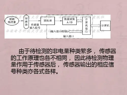
摘要:采用单片机AT89C51作为简易入库小车的检测和控制核心。
车库黑圈和路面引导白线检测使用反射式红外传感器,车速和距离检测使用断续式光电开关,引导光源检测采用光敏电阻阵列。
基于自动控制原理,采用高效的H型PWM电路动态控制电机的转速和转向;控制系统与电路用光电耦合器完全隔离以避免干扰。
添加电子罗盘模块后可使小车的环境适应性更强。
添加状态标志模块后,行驶过程中有声光提示,使得本设计更趋人性化。
关键词:智能小车寻迹寻光入库系统设计简易入库小车,根据题目要求,系统可以划分为控制部分和信号检测部分。
其中信号检测部分包括:光源探测模块、路程测量模块、路面检测模块、方向检测模块;控制部分包括:电机驱动模块、控制器模块、状态标志模块。
模块框图如图所示。
为了实现各模块的功能,分别做了几种不同的设计方案并进行了论证。
控制模块方案一:选用PIC、或AVR、或凌阳SPCE061A等作为控制核心;这些单片机资源丰富,可以实现复杂的逻辑功能,功能强大,完全可以实现对小车的控制。
但对于此题目而言,其有时得不到体现,成本也稍高,有点资源浪费。
方案二:采用单片机AT89C51作为系统控制器方案。
运算能力强。
软件编程灵活、功耗低、技术成熟和成本低。
基于以上分析,拟选用方案二。
光源探测本体要求小车在光源引导下,进入车库。
光源探测模块的功能主要是引导小车朝光源行驶。
方案一:采用红外温度感应器件。
用此可较为准确地寻找不远处的100W白炽灯。
但是,如此一来,电路实现较为复杂。
方案二:采用多光敏电阻阵列。
对每个光敏电阻状态进行编码,由此确定小车的转向。
考虑到实现的方便性,我们采用方案二。
路面检测路面检测模块实现小车进入白色车库、不压黑线、和沿白色引导线行驶。
探测路面黑圈和白色引导线的基本原理:光线照射到路面并反射,由于黑和白对光的反射系数不同,所以可以根据接收到的反射光强弱来判断黑白。
方案一:采用光敏传感器。
由于其他光源影响(特别是白天),会造成误判或漏判,效果不会很好。
1Housing Rated MountingOrdering no.Ordering no.diameter operating Power MOSFET,cable Power MOSFET,plug dist.(S n )1)Make &break switching Make &break switching M302)16mm Flush (built-in)CA30CLF16CP CA30CLF16CPM6M3025mmNon-flushCA30CLN25CPCA30CLN25CPM61)Object:Grounded steel plate 2)No humidity compensationProduct DescriptionProximity Sensors Capacitive Thermoplastic Polyester Housing Type CA,M 30,2-wire AC/DC•Featuring TRIPLESHIELD™Sensor Protection•Temperature stability•Humidity compensation circuit•Adjustable sensing distance 2-16mm or 2-25mm •Rated operational voltage:20-250VAC/DC •Output:Power MOSFET•Make and break switching function,selectable •LED indication•High noise immunity•Flush and non-flush types•Cable and plug versions availableType SelectionCapacitive proximity switch-es with either sensing dis-tance 16mm flush mounted or 25mm sensing distance non-flush mounted.2-wire AC/DC output with a switchfor choosing NO and NC switching.Grey M 30polyester housing with 2m PVC cable or plug.Ideal for use in level and plastic ma-chinery applications.T R I P L E S H I E L D ™Specifications2CA,M 30,AC/DCThe environments in which capacitive sensors are install-ed can often be un stable re-garding temperature,humidity,object distance and industrial (noise)interference.Because of this,Carlo Gavazzi offers as standard features in all TRIP-LESHIELD ™capacitive sen-sors a user-friendly sensitivity adjustment instead of having a fixed sensing range,extend-ed sensing range to accom-modate mechanically demand-ing areas,temperature stability to ensure minimum need for adjusting sensitivity if temper-ature varies and high immuni-ty to electromagnetic interfer-ence (EMI).Note:Sensors are factory set (default)to maximum rated sensing range.Adjustment GuideInstallation HintsCapacitive sensors have the unique ability to detect al-most all materials,either in li-quid or solid form.Capacitive sensors can detect metallic as well as non-metallic ob-jects,however,their tradition-al use is for non-metallic materials such as:•Plastic IndustryResins,regrinds or mould-ed products.•Chemical IndustryCleansers,fertilisers,liquid soaps,corrosives and pe-trochemicals.•Wood IndustrySaw dust,paper products,door and window frames.•Ceramic &Glass IndustryRaw material,clay or finished products,bottles.•Packaging IndustryPackage inspection for level or contents,dry goods,fruits and vegetables,dairyproducts.Materials are detected due to their dielectric constant.The bigger the size of an object,the higher the density of ma-terial,the better or easier it is to detect the object.Nominal sensing distance for a capaci-tive sensor is referenced to a grounded metal plate (ST37).For additional information regarding dielectric ratings of materials please refer to Technical Information.DimensionsTypeAB C D E F SW Ømm mm mm mm mm mmCA30CLF16CP(-M6)M 30x 1.5x 50285013.615.4536CA30CLN25CP(-M6)M 30x 1.5x 50286213.615.4536Not correctCorrectThe cable should not be pulledA proximity switch should not serve as mechanical stopAny repetitive flexing of the cable should be avoided3Wiring DiagramDelivery Contents•Capacitive switch:CA30..CL...CP (-M6)•Screw driver •2nuts•Packaging:Cardboard box•Installation &Adjustment Guide (MAN CAPENG/GER)Accessories•Plugs CONH6A..serie.For further information please refer to “Accessories”.CA,M 30,AC/DC。
ST178制作的反射式红外传感器电路图
ST178制作的反射式红外传感器电路图
红外线光电传感器ST178,ST178由4个管脚组成,是集发射和接收于一体的传感器。
发射和接收管分别采用高发射功率红外线光电二极管和高灵敏度光电晶体管组成。
工作的范围可达到4 mm~10 mm左右,采用非接触监测的方式。
经过反复试验证实,ST178红外线光电传感器的发射管要加500 Ω的电阻用来限流,而接收管则要接20 kΩ上拉电阻,两管均接5 V电源,工作时电压达到4.8 V,当距离发射头或接收头1cm左右的位置有障碍物阻挡时电压迅速降到1 V。
具体电路如图3所示。
74LS04六反相器
型号:HD74LS04P
封装:DIP14
品牌:日立(品牌或有时变,注重品牌者购买前请以询问核实为准)功能:六反相器
备注:以下参数仅供参考
建议操作条件:
直流电气特性
交流电气特性:
AC Electrical Characteristics VCCe2.0V to 6.0V, CLe50 pF, tretfe6 ns (unless otherwise specified)交流电气特性:
应用电路:。