CX425小型光电传感器使用说明书
- 格式:pdf
- 大小:4.04 MB
- 文档页数:1

光电传感器使用说明一、光电传感器的工作原理和分类1. 光电二极管(Photodiode):它是一种常见的光电传感器,可将光信号转化为电流信号。
光电二极管通过感光面积的调整,可实现对不同光强的测量。
2. 光敏电阻(Light-dependent resistor,LDR):它是一种依靠光线照射而改变电阻值的传感器。
光敏电阻的电阻值与光线强度成反比关系,因此可以用来测量光线的亮度。
3. 光电三极管(Phototransistor):它结构上类似于普通的晶体管,但在基区和发射区之间加上了一个光敏区。
当光照射到光电三极管时,会产生电流放大效应,从而可以将光信号转化为电流信号。
4. 光电耦合器(Optocoupler):它是将光电二极管和晶体管封装到一个封装内,用光绝缘的方式实现输入与输出之间的电气隔离。
光电耦合器在电气隔离和信号传输方面有重要的应用,可以用于电路隔离、信号转换等。
二、光电传感器的安装和调试在安装和调试光电传感器时,需要注意以下几点:1.安装位置的选择:根据具体的应用需求,选择合适的安装位置。
要确保光线能够正常照射到传感器的感光面,避免遮挡和干扰。
2.供电电压的选择:根据传感器的额定电压和工作电压范围,选择适当的供电电源。
要确保供电电压的稳定性,以免对传感器的工作产生影响。
3.输出信号的接收和处理:根据传感器的输出信号类型和电平,选择合适的接收和处理电路。
可以通过模拟电路或数字电路来处理传感器的输出信号。
4.灵敏度的调节:根据具体的应用需求,调节传感器的灵敏度。
对于光电二极管和光敏电阻等传感器,可以通过调节外部电阻来实现。
三、光电传感器的应用领域1.自动控制:光电传感器可以用于自动控制系统,如照明控制、清晰度检测、颜色识别等。
通过检测环境光照的变化,实现对设备的自动控制。
2.测量仪器:光电传感器可以用于测量仪器中,如光谱仪、测量器等。
通过测量光线的强弱、波长等,实现对物理量的测量。
3.光通信:光电传感器可以用于光通信系统中,如光纤通信、光模块等。
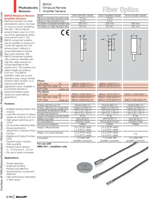
Photoelectric Sensors2.144BMOA Miniature Remote Amplifier SensorsNeed the precision of a laserphotoelectric sensor, but have no room to mount something that big? Ultra miniaturesensing heads down to 2 mmcan fit into applications wheremost sensors won’t. The BMOA component systems use an amplifier to power and control the signals from the sensing head, making it a unique alternative to typical fiber optic solutions. The BMOA component systems offer maximum flexibility with high flex cable versions for moving applications likerobotic arms. The systems can detect targets as small as 0.05 mm. The BMOAamplifiers make set-up and operation easy, using a simpledynamic teach function, or amanual push-button adjustment mode. Available in economical discrete or advanced analog outputversions to solve difficult applications.Features– Smallest sensing head in the industry– Laser-like precision to detect targets as small as 0.05 mm – High speed switching up to 5 kHz– 50 ms pulse stretching delay – Simple pushbuttonadjustment of dynamic teach function– Stability and Output Function LEDs– Discrete output versions PNP and NPN– Analog Output versions 0…10 Vdc and 4…20 mA – Din-rail or panel mountable Applications– Thread detection – Small part profiling – Robotic end-effectors– Semiconductor component detection– High performance alternative to fiber opticsBMOAMiniature Remote Amplifier SensorsBMO A01... amplifiers only.C o u r t e s y o f C M A /F l o d y n e /H y d r a d y n e ▪ M o t i o n C o n t r o l ▪ H y d r a u l i c ▪ P n e u m a t i c ▪ E l e c t r i c a l ▪ M e c h a n i c a l ▪ (800) 426-5480 ▪ w w w .c m a f h .c o m2.145t p76o amplifier connectoramplifier connectoramplifier connectorC o u r t e s y o f C M A /F l o d y n e /H y d r a d y n e ▪ M o t i o n C o n t r o l ▪ H y d r a u l i c ▪ P n e u m a t i c ▪ E l e c t r i c a l ▪ M e c h a n i c a l ▪ (800) 426-5480 ▪ w w w .c m a f h .c o mPhotoelectric Sensors2.146High SpeedBMO A01-I-PU-C-02BMO A01-I-NU-C-02SeriesDiscrete Output PNP Normally-open NPNNormally-open Analog Output 0...10 Vdc 4...20 mASupply VoltageVoltage Drop U d at I e Output Current (digital)Analog Output Type (Voltage)Analog Output Type (Current)Analog Output Load (voltage) min load Analog Output Load (current) Max Load Current Consumption I o (no load)Protections Response TimeSwitching FrequencyPulsed/Non-Pulsed Light Source Output FunctionOperating Temperature Range Degree of Protection per IEC 60529Sensitivity/Range Adjustment Power/Stability Indication Alarm Indication Output LEDHousing MaterialWeightConnection (to control system)10…30 Vdc< 2 V 100 mA 45 mAShort Circuit, Reverse Polarity100 µs 5 KHz Non-PulsedLight/Dark Selectable -10° C to +55° CIP 65Teach-in and ManualGreen LED Yellow LED ABS 55 g2 m PVC Cable ,3 x 26 AWGq w e rBMOAMiniature Remote Amplifier SensorsSensitivity settingAUT – the amplifier will determine the best setting for the application.MAN – this allows you to fine-tune the settings or manually adjust the sensor for difficult applications.Wiring DiagramsOutput GNDOutput GNDrC o u r t e s y o f C M A /F l o d y n e /H y d r a d y n e ▪ M o t i o n C o n t r o l ▪ H y d r a u l i c ▪ P n e u m a t i c ▪ E l e c t r i c a l ▪ M e c h a n i c a l ▪ (800) 426-5480 ▪ w w w .c m a f h .c o mFiber Optics/photoelectricObject Resolution for Diffuse Sensors42-2-4-6-8Y(mm)055M, 06TM & 66RMYMeasuring Arrangement:900a standard resolution amplifier.04SM, 05TM & 66RMthe beam at certain ranges.Sensing Distance for Diffuse Sensors0.8% 1.6% 3.1% 6.3% 12.5% 25% 50% 100%Absolute Mode (ABS)This mode offers the maximum accuracy for allapplications. The amplifier will offer 8 stages ofCourtesyofCMA/Flodyne/Hydradyne▪MotionControl▪Hydraulic▪Pneumatic▪Electrical▪Mechanical▪(8)426-548▪www.cmafh.co m。
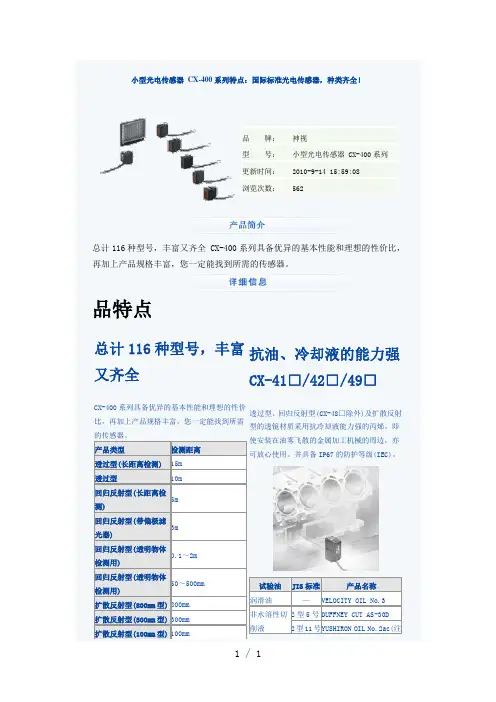
总计116种型号,丰富又齐全 CX-400系列具备优异的基本性能和理想的性价比,再加上产品规格丰富,您一定能找到所需的传感器。
品特点总计116种型号,丰富又齐全CX-400系列具备优异的基本性能和理想的性价比,再加上产品规格丰富,您一定能找到所需的传感器。
产品类型检测距离透过型(长距离检测)15m透过型10m回归反射型(长距离检测)5m回归反射型(带偏极滤光器)3m回归反射型(透明物体检测用)0.1~2m回归反射型(透明物体检测用)50~500mm扩散反射型(800mm型)800mm扩散反射型(300mm型)300mm扩散反射型(100mm型)100mm 抗油、冷却液的能力强CX-41□/42□/49□透过型、回归反射型(CX-48□除外)及扩散反射型的透镜材质采用抗冷却液能力强的丙烯。
即使安装在油雾飞散的金属加工机械的周边,亦可放心使用。
并具备IP67的防护等级(IEC)。
试验油JIS标准产品名称润滑油—VELOCITY OIL No.3非水溶性切削液2型5号DUFFNEY CUT AS-30D2型11号Y USHIRON OIL No.2ac(注IP67注:安装时,请避免使清洗液沾到附带于CX-48□中的反射镜上。
检测玻璃瓶检测小型药片检测薄型饼干基本性能红外光束之强光束 CX-412以2%以下的应差可检测小到0.4mm 的高低差 CX-441/443实现检测距离为15m 的长距离检测。
强劲的穿透力,亦可用于包装物内部的检测等。
相对于原有型号,先进的光学系统将检测性能提高约2.5倍。
即便是小到0.4mm 的高低差亦可准确地检测出。
不易受颜色的影响 CX-441/443回归反射型(带偏极滤光器) CX-491无论是白色工件,还是黑色工件,均可按照几乎相同的距内置偏极滤光器,就连镜面体亦可稳定检测。
离进行检测。
即使流水线上存在不同颜色的工件,需要切换工序时,也无需使用调节器调节。
设定距离为50mm的白色无光泽纸张和亮度为5的无光泽纸张(灰色)之间的检测距离差低于1%。

cx491光电参数CX491光电参数是指CX491型号的光电开关的性能指标。
光电开关是一种利用光电工作原理进行信号检测和测量的装置,广泛应用于自动化控制系统中。
CX491光电开关具有以下一系列的参数和特性。
1.检测距离:CX491光电开关的检测距离是指传感器能够在光照条件下正确检测到目标物体的最大距离。
该参数通常以米(m)为单位进行表示。
CX491光电开关的检测距离通常在几厘米到几米之间,具体取决于传感器的工作原理和设计。
2.工作电压:CX491光电开关的工作电压是指传感器正常工作所需的电压范围。
该参数通常以伏特(V)为单位进行表示。
CX491光电开关的工作电压通常为DC 10-30V,适用于工业自动化控制系统中常见的24V直流电源。
3.输出类型:CX491光电开关的输出类型是指传感器在检测到目标物体后输出的信号类型。
常见的输出类型包括PNP型(正逻辑)和NPN 型(负逻辑)。
PNP型传感器在检测到目标物体时输出高电平信号(通常为电源电压),而NPN型传感器在检测到目标物体时输出低电平信号(通常为零电位)。
4.输出状态:CX491光电开关的输出状态是指传感器在检测到目标物体时输出的信号状态。
常见的输出状态包括有源输出和无源输出。
有源输出是指输出端需要提供额外的电源来驱动负载,而无源输出则是指输出端直接输出开关信号,不需要额外的电源。
5.响应时间:CX491光电开关的响应时间是指传感器从检测到目标物体到输出信号发生变化的时间。
响应时间通常以毫秒(ms)为单位进行表示。
CX491光电开关的响应时间通常在几毫秒到几十毫秒之间,具体取决于传感器的工作原理和设计。
6.环境温度:CX491光电开关的环境温度是指传感器正常工作的环境温度范围。
该参数通常以摄氏度(℃)为单位进行表示。
CX491光电开关的环境温度通常为-25℃至+55℃,适用于大多数工业环境。
7.隔离电压:CX491光电开关的隔离电压是指开关输入和输出之间的电气隔离能力。
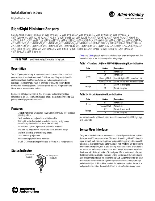
Installation InstructionsOriginal InstructionsRightSight Miniature SensorsCatalog Numbers 42EF-D2JBAK-A2, 42EF-D2JBAK-F4, 42EF-D2KBAK-A2, 42EF-D2KBAK-F4, 42EF-D2MPAK-A2, 42EF-D2MPAK-F4,42EF-D2MPAK-Y4, 42EF-P2JBB-A2, 42EF-P2JBB-F4, 42EF-P2KBB-A2, 42EF-P2KBB-F4, 42EF-P2MPB-A2, 42EF-P2MPB-F4, 42EF-P2MPB-Y4, 42EF-R2JBB-F4, 42EF-R2JBBT-A2, 42EF-R2JBBT-F4, 42EF-R2KBB-A2, 42EF-R2KBB-F4, 42EF-R2KBB-Z31, 42EF-R2KBBT-A2, 42EF-R2KBBT-F4, 42EF-R2MEB-F4, 42EF-R2MNB-A2, 42EF-R2MNB-F4, 42EF-R2MNB-Y4, 42EF-R2MNBT-A2, 42EF-R2MNBT-F4, 42EF-R2MPB-A2, 42EF-R2MPB-A5, 42EF-R2MPB-A6, 42EF-R2MPB-F4, 42EF-R2MPB-Y4, 42EF-R2MPBT-A2, 42EF-R2MPBT-A5, 42EF-R2MPBT-F4, 42EF-R2MPBT-Y4, 42EF-S1JBA-A2, 42EF-S1JBA-F4, 42EF-S1KBA-A2, 42EF-S1KBA-F4, 42EF-S1MEA-F4, 42EF-S1MNA-A2, 42EF-S1MNA-F4, 42EF-S1MNA-Y4, 42EF-S1MPA-A2, 42EF-S1MPA-F4, 42EF-S1MPA-Y4DescriptionThe 42EF RightSight™ family of photoelectric sensors offers high-performance general-purpose sensing in a compact, flexible package. They are designed for applications where simplified installation and maintenance are required. RightSight sensors provide a range of mounting options. The sensors can be through-hole mounted against a surface or can be installed using the threaded 18mm base or nose mounting options.Designed to withstand the rigors of food processing and material handlingenvironments, the 42EF RightSight standard models can withstand repeated 1200 psi and IP69K high-pressure washdowns.Features•Compact right angle housing with universal 18 mm threaded nose and base mounting options•Fixed, teachable, and adjustable sensitivity models•360° highly visible (status indicators helps operators verify proper operation regardless of sensor installation location)•Visible status indicator light-source for ease of alignment•Alignment aid helps achieve excellent reliability operating margin •Dual (NPN and PNP), NPN or PNP only models •Linear sensitivity adjustment•IP67 with 1200 psi; IP69K rated enclosure•IO-Link 1.1 Communication protocol that is offered in all standard modesStatus IndicatorTable 1 and Table 2 provide indicator status in the RUN mode, during operation. The sensor is always in run mode except when being taught.See for additional details about the operation of the 42EF RightSight in IO-Link mode.Sensor User InterfaceThe green status indicator can also serve as a set-up alignment aid that indicates that a margin of 1.5 has been reached. The sensor is receiving at least 1.5 times the signal strength back from the target that is required to trigger an output signal. In general, it is desirable to have a higher margin to help overcome any deteriorating environmental conditions, that is, dust build-up on the sensor lens. When aligning the sensor, the optimum performance can be obtained if this margin indicator is illuminated with the target in place. When aligning diffuse mode sensors, be sure that the sensitivity is set at its maximum setting; use the single-turn adjustment knob on the front panel. Pan the sensor left, right, up, and down to center the beam on the target. Decrease this setting to help prevent the sensor from detecting a background object. If this problem persists, the application requires the use of a background suppression, sharp cutoff diffuse, or retroreflective sensing mode.IMPORTANTSAVE THESE INSTRUCTIONS FOR FUTURE USE.IndicatorIndicatorTable 1 - Standard I/O (Auto PNP/NPN) Operating Mode IndicationColorStatus Description GreenOFF Power is off ON Power is onFlashing (6 hz)Unstable light: 0.8 X < margin < 1.5 X Flashing (1.4 hz)Output short circuit protection activeOrangeOFF Output de-energized ON Output energizedTable 2 - IO-Link Operation Mode IndicationColor Status Description GreenOFF Power is off Flashing (1 Hz)Power is onOrangeOFF Output de-energized ON Output energized2Rockwell Automation Publication 42EF-IN008B-EN-P - August 2020RightSight Miniature Sensors Installation InstructionsWiring DiagramsThe quick-disconnect connector is shown in the following diagrams. The pin numbers correspond to male connectors on the sensor.Figure 1 - Micro (M12) Male QD on Pigtail and Integral Pico (M8) Male QDOutput WiringFigure 2 - Light Operate PNP and NPN Models(42EF-D2JBAK-x , 42EF-P2JBB-x , 42EF-R2JBB-x , 42EF-S1JBB-x ) (a)Figure 3 - Dark Operate PNP and NPN Models(42EF-D2KBAK-x , 42EF-P2KBB-x , 42EF-R2KBB-x , 42EF-S1KBB-x ) (a)Figure 4 - PNP Complementary Models(42EF-D2MPAK-x , 42EF-P2MPB-x , 42EF-R2MPB-x , 42EF-S1MPB-x ) (a)Figure 5 - NPN Complementary Models(42EF-D2MNAK-x , 42EF-P2MNB-x , 42EF-R2MNB-x , 42EF-S1MNB-x ) (a)The IO-Link output pin 4 (black) does not support the connection of multiple sensors in series (for example, one sensor powering the next sensor). Theconnection of multiple sensors in series can be achieved when using pin 2 (white) outputs or by ordering a non-IO-Link catalog number. See theRockwell Automation® Knowledgebase or contact your local distributor for specific ordering information. For additional information about sensor operation in IO-Link mode, see publication 42EF-UM001.Approximate Dimensions [mm (in.)]Typical Response CurvesFigure 6 - Visible Red Polarized Retroreflective— 3.0 m Margin CurveFigure 7 - Visible Red Diffuse—500 mm Margin Curve(a)Replace the x in the catalog number with a suffix from Table 3.Table 3 - Connection TypesDescription Cat. No. Suffix2 m (6.6 ft) cable-A24-pin DC micro (M12) QD on 150 mm (6 in.) pigtail -F44-pin DC pico (M8) QD on 150 mm (6 in.) pigtail-Y412321M12 MaleM8 Male+V-VBlue (3)Black (4)White (2)Brown (1)PNP light operate or IO-Link NPN light operate or disabled (IO-Link operation default)+V-VBlue (3)Black (4)White (2)Brown (1)PNP dark operate or IO-Link NPN dark operate or disabled (IO-Link operation default)+V-VBlue (3)Black (4)White (2)Brown (1)PNP light operate or IO-Link PNP dark operate or disabled (IO-Link operation default)+V-VBlue (3)Black (4)White (2)Brown (1)NPN light operate or IO-LinkNPN dark operate or disabled (IO-Link operation default)Sensitivity Adjustment (diffuse and glass fiber-110100Distance to Reflector (mm)O p e r a t i n g M a r g i n0.110100011010001001100Distance (mm)M a r g i n (X )Rockwell Automation Publication 42EF-IN008B-EN-P - August 20203RightSight Miniature Sensors Installation InstructionsFigure 8 - Infrared Sharp Cutoff - 130 mm Margin CurveFigure 9 - Visible Red Polarized Retroreflective—3.0 m Beam PatternFigure 10 - Visible Red Diffuse—500 mm Beam PatternFigure 11 - Infrared Sharp Cutoff - 130 mm Beam PatternFigure 12 - Transmitted Beam Receiver—8 m Beam PatternFigure 13 - Transmitted Beam Receiver—Margin CurvesFigure 14 - Transmitted Beam Receiver—20 m Beam PatternAccessories1.010.0100.02.5425.4254Distance (m)O p e r a t i n g M a r g i nDistance (m)B e a m D i a m e t e r (m m )-535-11-3Distance to Target (mm)B e a m D i a m e t e r (m m )-8-6-4-20246812010080604020Distance to Target (mm)B e a m D i a m e t e r (m m )DescriptionCat. No.4-pin DC micro, 2 m (6.5 ft) cordset 889D-F4AC-2Swivel/tilt bracket (see Figure 16)60-2649Straight bracket60-2656Right angle bracket (see Figure 15)60-2657Mounting kit 60-2716Clamp style bracket 871A-BP18Flush mount adaptor60-25904-pin DC micro field-mount terminal chamber871A-TS4-DM 1.25 in. diameter reflector 92-473 in. diameter reflector92-39-0.2-0.15-0.1-0.0500.050.10.150.20.002.004.00 6.008.0010.00Distance (m)B e a m D i a m e t e r (m )1100100011010010Distance (m)O p e r a t i n g M a r g i n-0.5-0.4-0.3-0.2-0.100.10.20.30.40.50510152025Distance (m)B e a m D i a m e t e r (m m )Publication 42EF-IN008B-EN-P - August 2020 | Supersedes Publication 42EF-IN008A-EN-P - January 2016Copyright © 2020 Rockwell Automation, Inc. All rights reserved. Printed in the U.S.A.Rockwell Otomasyon Ticaret A.Ş. Kar Plaza İş Merkezi E Blok Kat:6 34752, İçerenköy, İstanbul, Tel: +90 (216) 5698400 EEE Yönetmeliğine UygundurAllen-Bradley, expanding human possibility, RightSight, and Rockwell Automation are trademarks of Rockwell Automation, Inc.Trademarks not belonging to Rockwell Automation are property of their respective companies.Your comments help us serve your documentation needs better. If you have any suggestions on how to improve our content, complete the form at rok.auto/docfeedback .For technical support, visit rok.auto/support.PN-59564210001372107 Ver 01Waste Electrical and Electronic Equipment (WEEE)Rockwell Automation maintains current product environmental compliance information on its website at rok.auto/pec .At the end of life, this equipment should be collected separately from any unsorted municipal waste.Figure 15 - Right Angle Bracket #60-2657Figure 16 - Swivel/Tilt Bracket #60-2649SpecificationsAttribute 42EF-*J*42EF-*K*42EF-*M*Certifications c-UL-us Listed and CE Marked for all applicable directives Vibration 10…55 Hz, 1 mm (0.04 in.) amplitude, meets or exceeds IEC 60947-5-2Shock 30 G with 1 ms pulse duration, meets or exceeds IEC 60947-5-2Relative humidity 5…95% (noncondensing)Ambient-light immunity •Incandescent light: 5000 lux •Sunlight: 20,000 lux User InterfaceStatus indicators •Green (power and margin)•Orange (output) Electrical Adjustments Fixed or adjustment knob by cat. no.Voltage10…30V DC, I-O link: 18…30V DC Current consumption 30 mA, maxSensor protection False pulse, reverse polarity, overload, short circuit Outputs Response time • 1 ms (diffuse, polarized retroreflective)• 4 ms (transmitted beam)Output type PNP and NPN PNP OR NPN(based on cat. no.)Load current 100 mA Leakage current, max •PNP: 0.1 mA •NPN: 0.3 mA Mechanical Housing material Mindel™Lens material Acrylic Cover material Udel™Supplied accessories 18 mm mounting nutEnvironmental Enclosure type rating NEMA 4X, 6P, IP67, IP69K; 1200 psi (8270 kPa) washdown Operating temperature -25…+70 °C (-13…+158 °F)Connection type•2 m (6.6 ft) cable•4-pin DC micro (M12) QD on 150 mm (5.9 in.) pigtail •4-pin DC pico (M8) QD on 150 mm (5.9 in.) pigtail。
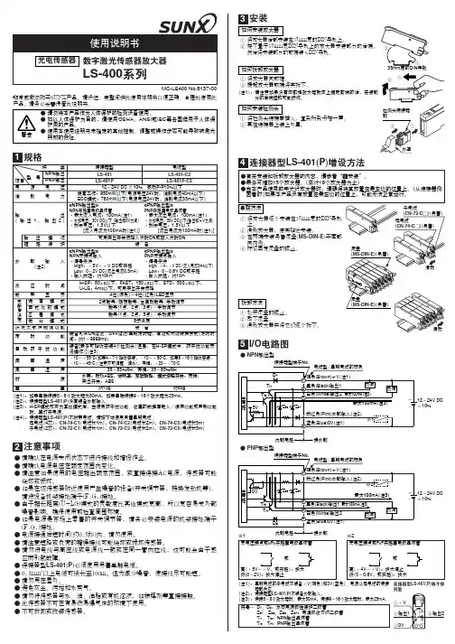
规格(注1):(注2):(注3):(注4):如果串联连接5~8个放大器为50mA ,如果串联连接9~16个放大器为25mA 。
连接器型LS-401(P )没有装备外部输入。
H-SP 模式改变为其他模式后,当使用防干扰功能、收集的数据库载入/保存功能或复制功能时,再打开电源。
连接器型LS-401(P )不附带电缆。
请按下述使用另售单触电缆 。
母电缆(4芯):CN-74-C1(电缆长1m ),CN-74-C2(电缆长2m ),CN-74-C5(电缆长5m )子电缆(2芯):CN-72-C1(电缆长1m ),CN-72-C2(电缆长2m ),CN-72-C5(电缆长5m )注意事项●●●●●●●●●●●●●●●●请确认在电源关闭状态下进行接线和增设作业。
请确认电源电压在额定范围内变化。
请注意如果使用的电压超出额定范围,或直接连接AC电源,传感器可能烧坏或损坏。
如果在该传感器附近使用产生噪音的设备(开关调节器,转换发动机等),请将设备机架接地端子(F.G.)接地。
由于超长距离(U-LG)模式的灵敏度比其他模式更高,所以更容易受外部噪音影响。
确保使用前检查周围环境。
如果电源是市场上零售的开关调节器,请务必安装电源的机架接地端子(F.G.)接地。
电源接通后短时间(约0.5秒)内,请勿使用。
请注意短路或负荷的错误接线可能烧坏或损坏传感器。
请勿将电线与高压线或电源线一起或在同一管内拉线,这可能会由于感应而引起故障。
连接器型LS-401(P )必须使用另售单触电缆。
0.3mm 2以上电缆可延长至100m。
但为减少噪音,使接线尽可能短。
请勿用在屋外。
避免灰尘、污垢和水蒸气。
请勿将传感器与水、油、油脂或有机溶液,如稀释剂等直接接触。
此传感器不可在有易燃易爆气体的环境下使用。
不可拆卸或改装传感器。
MC-LS400 No.8137-00非常感谢您购买SUNX产品。
请仔细、完整阅读此使用说明书以便正确、合理地使用此产品。
请务必妥善保管此说明书。

4路循迹传感器模块使用说明 一模块描述此模块是为智能小车 、 机器人等自动化机械装置提供一种多用途的红外线探测系统的解决方案 。
该传感器模块对环境光线适应能力强 , 其具有一对红外线发射与接收管 , 发射管发射出一定频率的红外线 , 当检测方向遇到障碍物 ( 反射面)时 , 红外线反射回来被接收管接收 , 经过比较器电路处理之后 , 同时信号输出接口输出数字信号(一个低电平信号) ,可通过电位器旋钮调节检测距离,有效距离范围2 ~ 6 0cm ,工作电压为3.3V-5V 。
该传感器的探测距离可以通过电位器调节、具有干扰小、便于装配、使用方便等特点,可以广泛应用于机器人避障 、 避障小车、流水线计数及黑白线循迹等众多场合。
二模块参数说明1当模块检测到前方障碍物信号时,电路板上红色指示灯点亮,同时OUT端口持续输出低电平信号 , 该模块检测距离2~60cm, 检测角度35 °, 检测距离可以通过电位器进行调节,顺时针调电位器,检测距离增加;逆时针调电位器 , 检测距离减少。
2 、传感器 属于 红外线反射探测 , 因此目标的反射率和形状是探测距离的关键 。
其中黑色探测距离最小 , 白色最大 ; 小面积物体距离小 , 大面积距离大。
3 、 传感器模块输出端口OUT可直接与单片机IO口连接即可, 也可以直接驱动一个5V继电器模块或者蜂鸣器模块;连接方式: VCC-VCC;GND-GND;OUT-IO4 、比较器 采用LM3 39 ,工作稳定;5 、可采用3 .3V -5V直流电源对模块进行供电。
当电源接通时,绿色电源指示灯点亮;6 、具有3mm的螺丝孔,便于固定、安装;7 、尺寸大小:中控板42mm × 38mm×12mm (长 ×宽×高)小板25mm ×12mm×12mm(长×宽 ×高)8 、 每个模块在发货已经将阈值比较电压通过电位器调节好,买家也可以根据实际情况进行调节(提示:模块反射距离越大,越容易误触发)三模块接口说明( 16线制)红外探头VCCGNDOUT对应接入中控板VCCGNDINx中控板供电 : 模块6p排针接口处V CC外接3.3V-5V电压 (可以直接与5v单片机和3.3v单片机相连 ) ; GND外接GND;OUT1-OUT4接单片机IO口四模块测试说明测试探头:移开探头前面所有物体,且探头不要指向有阳光的地方(光线对探头有较大干扰) ,将探头板接上电源后用万用表测量OUT和GND之间的电压,正常范围应该在0.6v-2.5v之间,用白纸挡在探头前,用万用表测量OUT和GND 之间的电压,正常范围应该接近0V.简单的说,就是用白纸挡住探头后,OUT和GND之间的电压会有一个明显的降低,这样就算正常。

微型光电传感器(放大器内藏)CX-20 系列非常感谢您使用SUNX传感器,请认真仔细的阅读此说明书从而保证您正确合理的使用本产品,请将此说明书放于一个方便您快捷查讯的地方。
本产品不是一种安全的传感器,它的用途不包括特意用来保护生命和阻止机器机器某些不安全部件带来的人身体伤害或财产损失。
规格表:注:1)模式序号中带“-J”连接类型。
例如:CX-21-J使用的电缆如下图所示:(这两种类型应为透光型)图:CN-24E-C2(直型,4芯,长2m)CN-24EL-C2(弯形,4芯,长2m)CN-24E-C5(直型,4芯,长5m)CN-24EL-C5(弯形,4芯,长5m)带后缀“S”代表具有自检功能的传感器(NPN)。
(不包括PNP输出型,CX-23,CX-28,CX-28IR和接插型。
)这种回射型传感器带有“-Y”代表RF-230反射器的感应器。
(不包括接插型)如:CX-29-Y,CX-29-PN-J-Y2)带偏振片的回射型传感器可能不能通过透明胶卷稳定地检测出特定的或光滑的物质,这是由于透明胶卷已将光线反射了。
(传感对象的实例)用清晰胶卷包裹的罐。
覆盖塑料胶卷的铝片。
金银色(光滑的)标签或包装纸。
3)反射型传感器的感应范围标示。
传感器能检测出小于0.1m远的物质(CX-28□型,CX-28IR □型:50mm)4) 扩散反射型传感器的感应范围由白色不光滑的纸张说明(200╳200mm)5) 如果想要在-15 0C或更低下使用传感器,请与我们办公室联系。
2、警告确保在配线时关掉电源。
确保供给电压变化在允许范围内。
当在供给电压上使用一台商业交换机时,将供给电源的F.G.终端接地。
一些设备运行有噪音时,如一台交换机或一台反相发动机放得离传感器太近,将设备的F.G.终端接地。
不要在转换到供给电源的50ms瞬间使用传感器。
将配对电缆连到连接型传感器时,加紧转矩≤0.4N·m 电缆加长总计应≤100m (用≥0.3mm2的电缆).不要在高压线或电力传输线附近该传感器,也应尽量避免在电缆管道附近使用该设备。
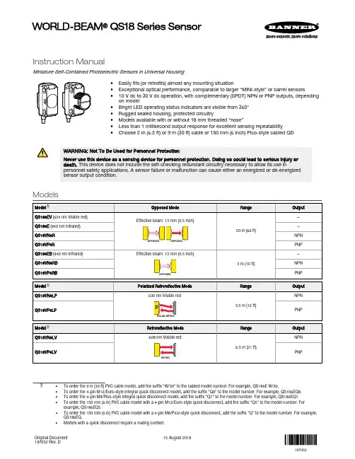
Instruction ManualMiniature Self-Contained Photoelectric Sensors in Universal Housing•Easily fits (or retrofits) almost any mounting situation•Exceptional optical performance, comparable to larger “MINI-style” or barrel sensors•10 V dc to 30 V dc operation, with complementary (SPDT) NPN or PNP outputs, depending on model•Bright LED operating status indicators are visible from 360°•Rugged sealed housing, protected circuitry•Models available with or without 18 mm threaded “nose”•Less than 1 millisecond output response for excellent sensing repeatability•Choose 2 m (6.5 ft) or 9 m (30 ft) cable or 150 mm (6 inch) Pico-style cabled QDWARNING: Not To Be Used for Personnel ProtectionNever use this device as a sensing device for personnel protection. Doing so could lead to serious injury or death. This device does not include the self-checking redundant circuitry necessary to allow its use inpersonnel safety applications. A sensor failure or malfunction can cause either an energized or de-energized sensor output condition.Modelssuffix "W/30" to the cabled model number. For example, QS186E W/30.•To order the 4-pin M12/Euro-style integral quick disconnect model, add the suffix "Q8" to the model number. For example, QS186EQ8.•To order the 4-pin M8/Pico-style integral quick disconnect model, add the suffix "Q7" to the model number. For example, QS186EQ7.•To order the 150 mm (6 in) PVC cable model with a 4-pin M12/Euro-style quick disconnect, add the suffix "Q5" to the model number. For example, QS186EQ5.•To order the 150 mm (6 in) PVC cable model with a 4-pin M8/Pico-style quick disconnect, add the suffix "Q" to the model number. For example,QS186EQ.•Models with a quick disconnect require a mating cordset.WORLD-BEAM ® QS18 Series SensorOriginal Document 197052 Rev. D15 August 2018197052 - Tel: +1-763-544-3164P/N 197052 Rev. DWiring DiagramsQS18 with NPN Outputs–+QS18 with PNP Outputs–+QS18 Emitters–+Key1 = Brown2 = White3 = Blue4 = BlackQuick disconnect wiring diagrams are functionally identical.Installing FibersCutting Unterminated Plastic Fibers QS18V..6FPUnterminated plastic fibers are designed to be cut by the user to the length required for the application.To facilitate cutting, a Banner model PFC-1 cutting device is supplied with the fiber. Cut the fiberas follows:Figure 1. PFC-1 Cutting DeviceUse small ports for fiber sizes:•0.25 mm (0.01 inches)•0.5 mm (0.02 inches)Use large ports for fiber sizes:•0.75 mm (0.03 inches)• 1.0 mm (0.04 inches)• 1.5 mm (0.06 inches)1.Locate the control end of the fiber (the unfinished end).2.Determine the length of fiber required for the application. If using a bifurcated fiber, separate the two halves of the fiber atleast 51 mm (2 inches) beyond the fiber cutting location.3.Lift the top (blade) of the cutter to open the cutting ports.4.Insert one of the control ends through one of the cutting ports on the cutter so that the excess fiber protrudes from theback of the cutter.5.Double-check the fiber length, and close the cutter until the fiber is cut.ing a different cutting port, cut the second control end to the required length.Note: To ensure a clean cut each time, do not use a cutting port more than once.7.Gently wipe the cut ends of the fiber with a clean, dry cloth to remove any contamination. Do not use solvents or abrasiveson any exposed optical fiber.Installing Plastic Fibers QS18V..6FPFollow these steps to install the plastic fibers.Adapter InstallationFigure 2. Installing Plastic FibersP/N 197052 Rev. D - Tel: +1-763-544-316431.Slide the fiber gripper up to unlock it (A).2.If using 0.25 mm or 0.5 mm core fibers, slide the plastic fiber adapters onto the fibers,flush with the fiber ends.3.Carefully insert the prepared plastic fiber ends into the ports (B) as far as possible without applying extra force.4.Slide the fiber gripper down to lock the fibers in place (C).Installing Glass Fibers QS18V..6FFollow these steps to install the glass fibers.1.Slide the supplied o-ring on the sensor end of the fibers, as shown.2.Press the fiber ends firmly into the ports located on the front of the sensor.3.Slide the supplied u-shaped retaining clip into the slot in the sensor’s barrel until the clip snaps into place. - Tel: +1-763-544-3164P/N 197052 Rev. DSpecificationsSupply Voltage10 V to 30 V dc (10% maximum ripple) at less than 25 mA, exclusive of load Protected against reverse polarity and transient voltages Light SourceGlass Fiber Optic, Opposed and Diffuse mode models: Infrared, 940 nm Plastic Fiber Optic, Retroreflective, Convergent models: Visible red, 660 nm Fixed-Field and DVS models: Visible red, 630 nm AdjustmentsGlass Fiber Optic, Plastic Fiber Optic, Convergent, Diffuse, andRetroreflective mode models (only): Single-turn sensitivity (Gain) adjustment potentiometer Indicators2 LED indicators on sensor top:Green solid: Power on Amber solid: Light sensedAmber flashing: Marginal excess gain (1 to 1.5 times excess gain)Required Overcurrent ProtectionWARNING: Electrical connections must bemade by qualified personnel in accordance with local and national electrical codes and regulations.Overcurrent protection is required to be provided by end product application per the supplied table.Overcurrent protection may be provided with external fusing or via Current Limiting, Class 2 Power Supply.Supply wiring leads < 24 AWG shall not be spliced.For additional product support, go to .RepeatabilityOpposed Mode: 100 microsecondsDVS, DL and FF Modes: 90 microseconds All Other Modes: 150 microsecondsOutput ConfigurationSolid-state complementary (SPDT): NPN or PNP (current sinking or sourcing), depending on model;Rating: 100 mA maximum each output at 25 °CDVS, DL and FF Modes ON-state Saturation Voltage: less than 1.5 V at 10mA; less than 3 V at 100 mAAll Other Modes: ON-state Saturation Voltage: less than 1 V at 10 mA; less than 1.5 V at 100 mAProtected against false pulse on power-up and continuous overload or short circuit of outputs Output ResponseOpposed Mode: 750 microseconds ON; 375 microseconds OFF DVS, FF and DL Modes: 850 microseconds ON/OFF All Other Modes: 600 microseconds ON/OFFNote: 100 millisecond delay on power-up; outputs do not conduct during this time Construction ABS housing3 mm mounting hardware includedConnections2 m (6.5 ft) 4-wire PVC cable, 9 m (30 ft) 4-wire PVC cable, 4-pin Pico-style or Euro-style QD, 4-pin Pico-style or Euro-style 150 mm (6 in) QD,depending on model EnvironmentalIEC IP67; NEMA 6Operating ConditionsTemperature: –20 °C to +70 °C (–4 °F to +158 °F)95% at +50 °C maximum relative humidity (non-condensing)CertificationsNote: For performance specifications of the FF50 and FF100 models built prior to date code 17090, refer to document p/n 63908.DimensionsModel Suffix E, EV, R, and FF(0.12")(0.67")Model Suffix EB, RB3.0 mm (0.12")(0.82")Model Suffix DB, W3.0 mm (0.12")(0.82")P/N 197052 Rev. D - Tel: +1-763-544-31645Model Suffix FP††CV Models: 33.2 mm (1.31")Model Suffix CV15, CV45, D, DL, LV, LPModel Suffix F17.1 mm (0.67")(0.78")Model Suffix Q7Model Suffix Q8Model Suffix Q(e.g. QS186EQ)Model Suffix Q5(e.g. QS186EQ5)(e.g. QS186EQ7)(e.g. QS186EQ8)QDPico-Style QDEuro-Style QDM18 x 1 Jam NutM3 hardware packet contents:• 2 - M3 x 0.5 x 20 mm stainless steel screw • 2 - M3 x 0.5 stainless steel hex nut • 2 - M3 stainless steel washerPacking list:•Sensor•M18 x 1 jam nut •M3 hardware packet•Quick Start Guide, p/n 63687Performance Curves - Tel: +1-763-544-3164P/N 197052 Rev. DP/N 197052 Rev. D - Tel: +1-763-544-31647 - Tel: +1-763-544-3164P/N 197052 Rev. DAccessoriesWORLD-BEAM QS18 BracketsSMB18A•Right-angle mountingbracket with a curved slotfor versatile orientation•12-ga. stainless steel•18 mm sensor mountinghole•Clearance for M4 (#8)hardwareHole center spacing: A to B = 24.2Hole size: A = ø 4.6, B = 17.0 × 4.6, C = ø 18.5SMB312S•Stainless steel 2-axis,side-mount bracketA = 4.3 × 7.5,B = diam. 3,C = 3 ×15.3All measurements are in millimeters.P/N 197052 Rev. D - Tel: +1-763-544-31649Retroreflective TargetsGo to or see the Accessories section of your current Banner Engineering Corp catalog for complete information.Note: Polarized sensors require corner cube type retroreflective targets only.Plastic and Glass Fiber OpticsGo to or see the Accessories section of your current Banner Engineering Corp catalog for a list of plastic and glass fiber optic cables.Banner Engineering Corp. Limited WarrantyBanner Engineering Corp. warrants its products to be free from defects in material and workmanship for one year following the date of shipment. Banner Engineering Corp. will repair or replace, free of charge, any product of its manufacture which, at the time it is returned to the factory, is found to have been defective during the warranty period. This warranty does not cover damage or liability for misuse, abuse, or the improper application or installation of the Banner product.THIS LIMITED WARRANTY IS EXCLUSIVE AND IN LIEU OF ALL OTHER WARRANTIES WHETHER EXPRESS OR IMPLIED (INCLUDING, WITHOUT LIMITATION, ANY WARRANTY OF MERCHANTABILITY OR FITNESS FOR A PARTICULAR PURPOSE), AND WHETHER ARISING UNDER COURSE OF PERFORMANCE, COURSE OF DEALING OR TRADE USAGE. This Warranty is exclusive and limited to repair or, at the discretion of Banner Engineering Corp., replacement. IN NO EVENT SHALL BANNER ENGINEERING CORP. BE LIABLE TO BUYER OR ANY OTHER PERSON OR ENTITY FOR ANY EXTRA COSTS, EXPENSES, LOSSES, LOSS OF PROFITS, OR ANY INCIDENTAL, CONSEQUENTIAL OR SPECIAL DAMAGES RESULTING FROM ANY PRODUCT DEFECT OR FROM THE USE OR INABILITY TO USE THE PRODUCT, WHETHER ARISING IN CONTRACT OR WARRANTY, STATUTE, TORT, STRICT LIABILITY, NEGLIGENCE, OR OTHERWISE.Banner Engineering Corp. reserves the right to change, modify or improve the design of the product without assuming any obligations or liabilities relating to any product previously manufactured by Banner Engineering Corp. Any misuse, abuse, or improper application or installation of this product or use of the product for personal protection applications when the product is identified as not intended for such purposes will void the product warranty. Any modifications to this product without prior express approval by Banner Engineering Corp will void the product warranties. All specifications published in this document are subject to change; Banner reserves the right to modify product specifications or update documentation at any time. Specifications and product information in English supersede that which is provided in any other language. For the most recent version of any documentation, refer to: .© Banner Engineering Corp. All rights reserved。
OsiSense® XUM Miniature Photoelectric SensorsHigh performancein a small packageOffering long sensing distances and resistance to interference and light sources>Easy to installContributes to machine compactnessWider adjustment range>EconomicalIncreases profi tability>Readily availableContributes to machine performanceContentsMiniature diffuse, polarized retrorefl ective, thru-beam dedicated models and multimode photoelectric sensorsIntroduction p 2 and 3Three-wire, plastic dedicated models p 4 to 7Three-wire, metal dedicated models p 8 to 11Three-wire, plastic multimode p 12 and 13NOTE: Sensors described in this catalog are designed to be used for standard industrial presence sensingapplications. These sensors do not include the self-checking redundant circuitry necessary to allow fortheir use in safety applications.>Contributes to machine compactnessEasy to install:Compact product, the most commonly used standard size• Long sensing distances: up to 5 m (16.40 ft) retrore fl ective, 15 m (49.21 ft) thru-beam, and 1 m (3.28 ft) diffuse • High insensitivity to light sources: withstands up to 40,000 lux natural light/10,000 lux incandescent light • Good resistance to severe environments: -30 to 60 °C (-22 to 140 °F) with IP67 degree of protection rating (IP69 K or IP67 G available)50%50% energy consumption: twice as many sensors can be placed on thesame power supply >Increases profi tabilityEconomical and Simple:• NO/NC con fi guration switch located on the bottom of the sensor for protection against accidental adjustment• Output LED on the front face of thru-beam sensors for easier alignment during installation >Selection guide XUM photoelectric sensors 3-wire DC Polarized Retrore fl ective DiffuseM82 m cable 2 m cable 1 (3.28) 5 (16.40)M8 2 m cable Thru-Beam 15 (49.21) with adjustable sensitivitytransmitter + receiver 12–24 Vdc with protection against reverse polarityNO/NC con fi gurable par switchIP65, IP67 * For multimode thru-beam applications, see page 12 for appropriate transmitter and receiver selection.100%availabilitythroughoutthe world >Contributes to machine performanceReadily available:• Robust products designed to meet your needs• Particularly well suited for machines used in the assembly and packaging sectors, the automotive industry, conveying, etc.Packaging Automotive Materials handling Multimode 0...10 (32.81)depending on mode3-wire DCwith adjustable sensitivity IP67, IP69 K, IP67 G 12–24 Vdc with protection against reverse polarity Fixed NO or NC, PNP or NPN XUM9BPANL2 XUM9BNANL22 m cable5 (16.40) with re fl ector XUZC50Polarized Retrore fl ective XUM9BPBNL2XUM9BNBNL22 m cable 15 (49.21)Thru-Beamtransmitter + receiverDiffuse 2 m cable 0.77 (2.53) XUM5BPANL2 XUM5BNANL2XUM5BPBNL2 XUM5BNBNL2System Supplym (ft) M8XUM5A p CNM8XUZ C08567XUZMSV pp XUZMSH pp XUZMU01Catalog Numbers OsiSense® Photoelectric sensorsOptimumMiniature design, plasticThree-wire DC solid-state outputNO/NC confi guration switchXUZAM04524754XUZAM03524753Distance (m)Parallelmovement(cm)Vertical movementHorizontal movementParallelmovement(cm)XUZ C50Parallelmovement(cm)Distance (m) wiring diagramscurvesOptimumMiniature design, plasticThree-wire DC solid-state outputNO/NC confi guration switchDiffuse system, polarized retrorefl ective system (mm)Pre-cabled version Connector versionDescription - XUM5A p CNL2, XUM9A p CNL2Dimensions - XUM5A p CNL2,XUM9A p CNL2Description - XUM5A p CNM8,XUM9A p CNM8Dimensions - XUM5A p CNM8,XUM9A p CNM8(1) Confi guration switch(2) Output state LED(3) Stability and power-on LEDR: Reception, T: Transmission(1) Potentiometer(1) Confi guration switch(2) Output state LED(3) Stability and power-on LEDR: Reception, T: Transmission(1) Potentiometer(4) Adjustment potentiometer(5) Power-on LEDT: Transmission(1) Potentiometer(1) Confi guration switch(2) Output state LEDR: Reception(1) Output state LED on front face(4) Adjustment potentiometer(5) Power-on LEDT: Transmission(1) Potentiometer(1) Confi guration switch(2) Output state LED(3) Stability and power-on LEDR: Reception(1) Output state LED on front faceNO/NC confi guration switchNO/NC confi guration switchXUZ C08XUM 2B2KCL2T XUM 2B pp NL2RXUZ AM81Catalog Numbers OsiSense ® Photoelectric sensorsApplicationMiniature design, metalThree-wire DC solid-state output(+) BN (Brown)OUT/Output BK (Black)P a r a l l e l m o v e m e n t (c m )Horizontal movementP a r a l l e l m o v e m e n t (c m )XUZ C50P a r a l l el m o v e m e n t (cm )Distance (m)Characteristics, schemes, curvesOsiSense ® Photoelectric sensorsApplicationMiniature design, metalThree-wire DC solid-state outputDiffuse system (mm)Description - XUM 5B pp NL2Dimensions - XUM 5B pp NL2(3) Adjustment potentiometer.R: Reception, T: Transmission.Polarized retrorefl ective system (mm)NL2Dimensions - XUM 9B pp NL2Description - XUM 9B ppDescription - XUM 2BKCNL2T Dimensions - XUM 2BKCNL2T Dimensions - XUM 2B pp NL2R(2) Stability and power-on LED.Accessories (mm)Refl ectors Mounting bracket XUZ C08XUZ C50XUZ AM81(1) 2 x M3(1) Elongated holes 4.5 x 8OsiSense ® Photoelectric sensorsMulti-modeMiniature designThree-wire DC supply, solid-state outputXUM0APSAL5.Dimensions (mm)XUM0A ppp L2XUM0A ppp M8Elbowed connector501543_1501542_1XUM0A ppp M8XUM0A ppp L2XUZC50XUZ M2003XUZ2001XUZ 2003XUZ A50Catalog Numbers,dimensionsOsiSense ® Photoelectric sensorsMulti-modeMiniature designThree-wire DC solid-state output1 (+)4 OUT/Output 2 beam break input (1)(+) BN (Brown)OUT/Output BK (Black)Beam break input VI (Violet) (1)2/VI input:- not connected: beam madefl ection coef fi cientSpeci fi cations, wiring diagrams,curves(1) Beam break input on thru-beam transmitter only.The information and dimensions in this catalog are provided for the convenience of our customers. While this information is believed to be accurate, Schneider Electric reserves the right to makeupdates and changes without prior notifi cation and assumes no liability for any errors or omissions. Design: Schneider ElectricPhotos: Schneider Electric© 2010 Schneider Electric. All Rights Reserved.April 20109 0 0 6 C T 1 0 0 3Schneider Electric USA, Schneider Electric SensorCompetency Center1875 Founders DriveDayton OH 45420(800) 435-2121。
光电传感器调试方法说明书一、概述光电传感器是一种能够将光信号转换为电信号的装置,广泛应用于自动控制系统中。
本调试方法说明书旨在帮助用户正确使用和调试光电传感器,以确保其正常工作和高效性能。
二、安装与接线1. 安装:a. 在安装光电传感器之前,先确保传感器外壳表面无损坏或异物,并检查光电源线是否完好无损。
b. 选择合适的安装位置,通常应与被检测对象保持适当的距离,以获得更好的检测效果。
c. 使用固定支架或螺丝将光电传感器牢固地安装在选定的位置上。
d. 确保传感器与电源线的连接牢固可靠,避免线路短路或打结。
2. 接线:a. 首先,将光电传感器的输出线与控制器的输入线相连接。
确保正确连接,避免接反。
b. 确保电源线的正负极与控制器的电源输入相对应,防止电源极性错误。
三、调试步骤1. 所需工具和设备:a. 计算机或控制器,用于接收和处理传感器输出信号。
b. 示波器,用于观察传感器输出波形和信号响应。
c. 配套软件或编程器,用于在计算机或控制器上进行传感器参数设置和调试。
2. 调试步骤:a. 连接光电传感器与计算机或控制器,并确保连接正确、稳定。
b. 打开相应的调试软件或编程工具,进入传感器调试界面。
c. 根据需要,设置传感器的相关参数,如增益、灵敏度等。
注意参数的合理选择,以适应具体的检测要求。
d. 使用示波器监测传感器的输出波形,并根据实际情况调整参数,以获得最佳的检测效果。
e. 在控制器或计算机上设置传感器的输出信号阈值,以实现准确的触发和检测。
f. 在实际工作环境中进行适当的测试和验证,确保传感器的稳定可靠性。
四、注意事项1. 使用前,请仔细阅读光电传感器的用户手册,了解其功能和特点,避免误操作。
2. 在调试过程中,应注意安全,确保电源和线路的正常工作。
3. 如需更改传感器的参数设置,请谨慎操作,避免引起传感器损坏或系统故障。
4. 如遇到故障或问题,请及时联系厂家或供应商寻求帮助,避免私自修理造成更大的损失。
T 01:13:49+02:00Type code Q45AD9R Ident no.3037626Operating mode opposed mode sensor (receiver)Range0…60000 mm Ambient temperature-40…+70 °CVoltageNom. 8.2 VDC Non-actuated current consumption ð 1 mA Actuated current consumption ï 2.1 mA No-load current I 0ð 2.1 mAOutput functionlight operation, NAMUR Switching frequency ð 250 HzDevice designation Ex II 1 G Ex ia IIC T5Design rectangular, Q45Dimensions87 x 54.1 x 44.5 mm Housing material plastic, PBT Lensplastic, acrylic Connection cable, PVC Cable length2 mCable cross section2 x 0.5 mm Protection class IP67MTTF67 years acc. to SN 29500 (Ed. 99) 40 °C Protection typeEx ia IIC T6Ex approval acc. to conformity certificate KEMA 03ATEX 1441 X Switching stateLED reds ATEX category II 1 G, Ex zone 0s Cable, PVC, 2 m s Protection class IP67s Sensitivity adjusted via potentiometer s Operating voltage: 5…15 VDC sNAMUR output: dark <= 1.2 mA ; light >= 2.1 mAsAcc. to EN 60947-5-6 (NAMUR)Wiring diagramFunctional principleOpposed mode sensors consist of an emit-ter and receiver. They are installed opposite each other so that the light from the emitter is aimed directly at the receiver. When an ob-ject interrupts or weakens the light beam, the sensor switches. Opposed mode sensors are the most reliable photoelectric sensors for de-tection of opaque targets. An excellent con-trast between light and dark conditions and an extremly high excess gain are typical of this sensing mode, thus allowing operation over larger distances and under difficult conditions.Excess gain curveExcess gain in relation to the distanceT 01:13:49+02:00AccessoriesType codeIdent no.DescriptionDimension drawingIM1-22EX-R/24VDC7541210isolating switching amplifier, two channels; input for NAMUR signals; optional wire-break and short-circuit monitoring func-tion; selectable normally open or normally closed perfor-mance; removable terminal blocks; 18 mm wide; supply volt-age 24 VDCSMB30A 3032723Mounting bracket, stainless steel, for sensors with 30 mm threadSMB30FAM103011185Mounting bracket, stainless steel, for M10 x 1.5 thread,thread length 30 mmSMB30SC 3052521Mounting bracket, PBT black; for 30 mm thread; with 4screws M5 x 0.8T 01:13:49+02:00Operating manual Intended useThis device fulfills the directive 94/9/EC and is suited for use in explosion hazardous areas according to EN60079-0:2009, -11:2012, -26:2007.In order to ensure correct operation to the intended purpose it is required to observe the national regulations and directives.For use in explosion hazardous areas conform to classificationII 1 G (Group II, Category 1 G, electrical equipment for gaseous atmospheres).Marking (see device or technical data sheet)Ex II 1 G and Ex ia IIC T5 acc. to EN60079-0, -11 and -26Local admissible ambient temperature -25…+70 °CInstallation / CommissioningThese devices may only be installed, connected and operated by trained and qualified staff. Qualified staff must have knowledge of protection classes, directives and regulations concerning electrical equipment designed for use in explosion hazardous areas.Please verify that the classification and the marking on the device comply with the actual application conditions.This device is only suited for connection to approved Exi circuits compliant to EN60079-0 and -11. Please observe the maximum admissible electrical values.After connection to other circuits the sensor may no longer be used in Exi installations. When interconnected to (associated) electrical equip-ment, it is required to perform the "Proof of intrinsic safety" (EN60079-14).Installation and mounting instructionsAvoid static charging of cables and plastic devices. Please only clean the device with a damp cloth. Do not install the device in a dust flow and avoid build-up of dust deposits on the device.If the devices and the cable could be subject to mechanical damage, they must be protected accordingly. They must also be shielded against strong electro-magnetic fields.The pin configuration and the electrical specifications can be taken from the device marking or the technical data sheet.In order to avoid contamination of the device, please remove possible blanking plugs of the cable glands or connectors only shortly before in-serting the cable or opening the cable socket.service / maintenanceRepairs are not possible. The approval expires if the device is repaired or modified by a person other than the manufacturer. The most important data from the approval are listed.。
光电传感器的说明书
1 可以检测周围环境的亮度和光强
2 灵敏度可调(图中蓝色数字电位器调节)
4 工作电压3.3V-5V
5 输出形式 a 模拟量电压输出b 数字开关量输出(0和1)
6 设有固定螺栓孔,方便安装
7 小板PCB尺寸:3cm * 1.6cm
8 电源指示灯(红色)和数字开关量输出指示灯(绿色)
9 比较器采用LM393芯片,工作稳定
三小板接口说明(4线制)
1 VCC 外接3.3V-5V
2 GND 外接GND
3 DO 小板数字量输出接口(0和1)
4 AO 小板模拟量输出接口
四使用说明
1光敏电阻模块对环境光强最敏感,一般用来检测周围环境的亮度和光强。
2模块在无光条件或者光强达不到设定阈值时,DO口输出高电平,当外界环境光强超过设定阈值时,模块D0输出低电平;
3小板数字量输出D0可以与单片机直接相连,通过单片机来检测高低电平,由此来检测环境的光强改变;
4小板数字量输出DO可以直接驱动本店继电器模块,由此可以组成一个光电开关;
5小板模拟量输出AO可以和AD模块相连,通过AD转换,可以获得环境光强更精准的数值;。