
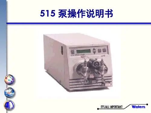
沃特斯泵操作说明书
- 格式:ppt
- 大小:224.00 KB
- 文档页数:18

水泵安装、使用、维护说明书Type NG slurry PumpINST ALL TION, OPERA TION, MAINTENANCEMANUAL一、水泵的安装Pump installation水泵的安装Pump installation1、水泵安装准备工作1. The preparation work for pump installation.(1)检查水泵和电机,确知在运输和装卸过程中没有损伤。
Check the pump and motor, ensure there were no damage during the transportation and load or unload.(2)检查工具和起重机械,并检查机器的基础。
Check the tools and lifting equipment and also the basement of machine. (3)检查配套提供的压力表及表座。
Check the manometer and gauge stand of affiliated equipments2、水泵安装顺序Pump installation order(1)整套泵运抵现场时,都已装好电机;校平底座时,可不必卸下水泵和电机。
The motor have been installed when a whole set of pump arrived scene. When collate the basement, no need to demount the pump and motor.(2)在水泥基础上安装水泵时,基础平面应用水平找平,待基础水泥凝固后将泵安装在基础上,并用水平仪检查水平情况,如不平,应用垫铁调正,直到水平为止,然后通过灌浆孔由混凝土浇灌底座和地脚螺栓孔眼。
When install pump on the cement base, regulate the foundation flat by the standard. Check the condition of standard by thegradienter, if not flat, regulate it by the parallels until horizontal, use concrete to irrigate basement and foundation bolt hole by the grout hole. (3)水泥干固后,检查底座和地脚螺栓是否松动,合适后拧紧地脚螺栓的螺母,最后再检查一下整台机组的水平度,稍有不平时,可用斜铁找平。

水泵操作说明一、前言水泵是一种用来运输液体的机械设备,广泛应用于工业、农业和民用领域。
本文将介绍水泵的操作步骤及注意事项,以确保安全高效地操作水泵。
二、准备工作1. 确保水泵所需的电源稳定可靠,并符合使用电压要求。
2. 检查水泵设备的连接管路、旋钮和阀门是否牢固,无渗漏情况。
3. 将水泵放置于平稳的地面或地基上,确保稳固。
4. 检查水泵的进水和出水口,确保没有堵塞或其他障碍物。
三、操作步骤1. 打开电源:将电源插头插入电源插座,并打开供电开关。
2. 检查运行方向:根据水泵的旋转方向箭头,确保电机和水泵的运行方向一致。
3. 开启进水阀:逐渐打开进水阀门,允许水进入水泵。
4. 启动水泵:按下启动按钮或开关,启动水泵设备。
5. 检查运行状态:观察水泵设备是否正常运转,并注意是否有异常噪音或振动。
6. 调整流量:根据实际需求,适当调整进水阀门的开度,控制水泵设备的流量。
7. 关闭水泵:当不再需要使用水泵时,首先关闭进水阀门,然后按下停止按钮或开关,停止水泵设备运转。
8. 断电:关闭电源开关,并拔掉电源插头。
四、注意事项1. 操作前务必熟悉水泵设备的使用说明和安全操作规程。
2. 在操作水泵前,应确保人员穿戴好必要的个人防护装备,如手套、安全鞋等。
3. 在启动水泵前,应检查周围环境是否存在易燃易爆物品,确保操作安全。
4. 切勿长时间运行水泵设备,以免引发设备过热或其他问题。
5. 定期检查水泵设备的油液、密封件以及电机等部件是否正常,并进行必要的维护和更换。
6. 在长时间不使用水泵时,应将水泵设备进行清洗、排干,并存放在干燥通风的地方。
7. 如遇突发情况或故障,请立即停止使用水泵,并寻求专业人士的帮助和维修。
五、结语正确操作水泵是确保其正常运行和延长使用寿命的重要一环。
通过遵循本操作说明,您可以安全高效地操作水泵设备。
如有任何疑问或需要进一步的帮助,请咨询专业人士或水泵设备厂家。
祝您工作顺利!。

WR10 3/8"Bolted Plastic Pumps Operating InstructionsPolypropyleneKynarRead these instructions completely before installation and start-up. It is the responsibility of the purchaser to retain this manual for reference. Failure to comply with the rec-ommendations stated in this manual could result in death, serious bodily injury and/or property damage including damage to the pump and/or voiding the factory warranty. Correct pump selection is crucial to the pump operation. Please assure pressure, temperature and chemical compatibility before installation. Please consult Warren Rupp, Engineering Specifications, Chemical Compatibility Chart, or your distributor if in doubt about any application.Operating Limitations for Various Elastomers Neoprene0°F (-18°C) to 200°F (93°C) Buna-N10°F (-12°C) to 180°F (82°C) Nordel-60°F (-51°C) to 280°F (138°C) Viton-40°F (-40°C) to 350°F (176°C) PTFE40°F (4°C) to 220°F (105°C) Polyurethane10°F (-12°C) to 170°F (77°C) XL TPE-20°F (-29°C) to 300°F (149°C) Geolast-40°F (-40°C) to 257°F (125°C) FDA Hytrel-20°F (-29°C) to 220°F (104°C) Operating Limitations for Plastic PumpsKynar (PVDF)10°F (-12°C) to 225°F (107°C) Polypropylene32°F (0°C) to 175°F (79°C) Maximum temperature limits are based upon mechanical stress only. Certain chemicals and environment conditions significantly reduce maximum safe temperature limits. Before pump operation, inspect all gasketed fasteners for looseness caused by gasket creep. Re-torque all loose fasteners to prevent leakage. Follow recommended torques stated in this manual. Failure of the sealing components creates the possibility of jetting or forceful discharge of pumped material at a potentially harmful velocity.Be certain that approved eye protection and protective clothing are always worn during installation, service, mainte-nance or when in the vicinity of the pump. Failure to follow these recommendations may result in serious injury or death.Never allow the piping system to be supported by the pump manifolds or valve housing. The manifolds and valve housing are not designed to support any structural weight and failure of the pump may result.Take action to prevent static sparking.Fire or explosion can result, especially when handling flammable liquids. The pump, piping, valves, containers, or other miscellaneous equipment must be grounded.Noise levels can exceed 85 dBA. Take precautions to prevent personal injury due to excessive pump noise.Do not exceed pump maximum operating pressure (found on label and/or operating manual.)Before doing any maintenance or repair on this pump,be certain all pressure is completely vented for the pump, suction, discharge, piping, and all other openings.In the event of a diaphragm rupture, pumped materialmay enter the air end of the pump and be discharged into the atmosphere. If pumping a product that is hazardousor toxic, the air exhaust must be piped to an appropriate area for safe disposition.WR10 Model3/8" Bolted Plastic PumpFlow RateAdjustable to . . . . . . . 0-6.8 gpm (26 lpm)Port SizeSuction . . . . . . . . 3/8" Female NPT (BSP) Discharge . . . . . . 3/8" Female NPT (BSP) Air Inlet . . . . . . . . . . . . 0.25" Female NPT Air Exhaust . . . . . . . . 0.25" Female NPT Suction Lift . . . . . . . . . . . 11' (3.4 m) Dry Teflon . . . . . . . . . . . . . . . . 11' (3.4 m) Dry Max. Particle Size (Dia.) 0.10" (2.25 mm)dB(A) Reading . . . . . . . . . . . . . . 78 dB(A)Shipping WeightPolypropylene . . . . . . . . . . . 3 lbs (1.4 kg)Kynar. . . . . . . . . . . . . . . . . . 3 lbs (1.4 kg)Caution: do not exceed 100 psig (6.8 bar) liquid or air supply pressure.Meters FeetD i s c h a r g e H e a d i n P S I 1530240 220 200 180 160 140 120 100 80 60 40 20 0 75 7065 60 55 50 454035 30 25 20 151056427895101520253035Capacity in Liters Per MinuteCapacity in U.S. Gallons Per Minute Displacement Per Stroke, 0.009 Gal . (0.034 L)Suffix Code Material A AcetalBN Buna-N, Nitrile N NeopreneND Nordel, EPDM TF PTFE FG HytrelXL XL, Santoprene VT VitonTXBonded TeflonWater Chamber Bolts50 in-lbs (5.7 N-m)Diaphragm Plates — Rubber 60 in-lbs (6.8 N-m)Diaphragm Plates — PTFE 60 in-lbs (6.8 N-m)Air Valve Cap Screws35 in-lbs (3.9 N-m)Pump Size Minimum Air Minimum SuctionLine Size Line Size 1/4"1/4"1/4"3/8"1/4"3/8"1/2"1/2"1/2"1"1/2"1"1-1/2"1/2"1-1/2"2"1/2"2"3"3/4"3"InstallationThe pump should be mounted in a vertical position.In permanent installations, the pump should be attached to plant piping using a flexible coupling on both the intake and discharge connections to reduce vibration to the pump and piping. T o further reduce vibration, a surge suppressor next to the pump may be used.Suction pipe size should be at least the same diameter as the inlet connection size, even larger if highly viscous fluid is to be pumped. If suction hose is used, it must be of a non-collapsible reinforced type. Discharge piping should be of at least the same diameter as the discharge connection. It is critical,especially on the suction side of the pump, that all fittings and connections are air tight or pumping efficiency will be reduced and priming will be difficult.Make certain the air supply line and connections and compressor are capable of supplying the required pressure and volume of air to operatethe pump at the desired flow rate. The quality of the compressed air source should be considered. Air that is contaminated with moisture and dirt may result in erratic pump performance and increased maintenance cost as well as frequent process “down time” when the pump fails to operate properly.Pump OperationThe pump is powered by compressed air.Compressed air is directed to the pump air chamber by the main air valve. The compressed air is separated from the fluid by a membrane called a diaphragm. The diaphragm in turn applies pressure on the fluid and forces it out of the pump discharge.While this is occurring, the opposite air chamber is de-pressurized and exhausted to atmosphere and fluid is drawn into the pump suction. The cycle again repeats, thus creating a constant reciprocating action which maintains flow through the pump. The flow is always in through the bottom suction connection and out through the top discharge connection. Since the air pressure acts directly on the diaphragms, the pressure applied to the fluid roughly approximates the air supply pressure supplied to the main air valve.WR10 REPAIR& MAINTENANCE KITS Air End Kit — Part #: WR10 AIR KIT Wetted End Kits Item Description Qty Part Number Part Number Description3Valve Spool U-Cup2P98-104A WR10 XL KIT XL Elastomer Kit5End Cap O-Ring2E500E WR10 G KIT Geolast Elastomer Kit 8Air Diverter1E500G9Valve Insert1E500H10Valve Gasket1E800J20Pilot Shaft O-Ring6E503B34Main Shaft O-Ring2E503BAIR VALVE ASSEMBLYItem Description Qty.Standard: Polypropylene Air Valve Assembly (Includes items 1-10)E8001Valve Body1E800A2Valve Spool1E500B3Valve Spool U-Cup2P98-104A4End Cap2E800D5End Cap O-Ring2E500E8Air Diverter1E500G9Valve Insert1E500H10Valve Gasket1E800J11Valve Screw410-050AIR END ASSEMBLYItem Description Qty.Standard: Polypropylene 12Center Section1E801A18Pilot Shaft1E803A19Pilot Shaft Spacer5E503C20Pilot Shaft O-Ring6E503B21Pilot Shaft Snap Ring2E503D22Shaft Retainer2E801B25Shaft Retainer Screw4E501C33Muffler106-034DIAPHRAGM ASSEMBLYItem Description Qty.TPE34Main Shaft O-Ring2E503B35Main Shaft110-02837Inner Diaphragm Plate2C12638Outer Diaphragm Plate210-023(poly) 10-040(kynar)40Diaphragm210-032(XL) (10-033)GeolastWET END ASSEMBLYItem Description Qty.Standard: Polypropylene Option 1: Kynar 44Water Chamber210-00210-03645Water Chamber Bolt (Long)410-05210-05246Water Chamber Bolt (Short)1210-05110-05150Valve Seat410-012(XL)10-029(Geolast)10-012(XL)10-029(Geolast)52Valve Stem410-00510-038 53Spring410-03010-030 60Manifold210-00310-037 62Foot Pad410-03510-035©2006 Warren Rupp,Inc.SMWR10F-Rev0976WARREN RUPP, INC.A Unit of IDEX Corporation 800 North Main StreetMansfield, OH 44901-1568 USA (419) 524-8388Fax: (419) Kynar® is a registered trademark of Penwalt Corp. Geolast® is a registered trademark of AES.Warren Rupp® is a registered tradename of IDEX Corporation.。

G型电磁调速型螺杆泵操作使用说明
一、泵的结构与工作原理
二、操作前的准备工作
1.确保电源连接正常,电机正常工作。
2.检查泵体及管道连接是否紧固,没有松动和泄漏。
三、泵的启动
1.打开电源开关,并确认电源指示灯亮起。
2.按下启动按钮,电机启动。
3.观察泵的工作状态,确保正常运转。
四、调节泵的流量与压力
1.使用调速开关来调节泵的流量。
将调速开关旋转至所需位置,以增大或减小泵的流量。
2.使用调速开关来调节泵的压力。
将调速开关旋转至所需位置,以增大或减小泵的压力。
五、操作中的注意事项
1.在使用过程中,定期检查泵体及管道连接是否紧固,没有松动和泄漏。
如有发现问题,应及时处理。
2.使用过程中如果发现异常声音、异味或者电机异常热,应立即停机检查。
3.切勿将泵用于输送易燃、易爆或有腐蚀性的液体,以免发生事故。
4.切勿超负荷运行泵,以免损坏设备。
5.在停机前,应先关闭调速开关,再切断电源。
六、泵的维护保养
1.定期清洗和维护泵体,清除积存污垢,保持泵体的清洁。
2.定期检查电机的绝缘状况,如发现损坏应及时更换。
3.定期检查泵体及管道连接部位是否有泄漏现象,及时处理泄漏点。
4.对泵进行定期维护,更换润滑油等易损件。
七、泵的停机
1.关闭调速开关,减慢电机转速。
2.断开电源,关闭电源开关。