板球系统用户手册和实验指导书 V1.16
- 格式:pdf
- 大小:2.40 MB
- 文档页数:43
内蒙古公共气象服务基础平台IMMESS 1。
0操作手册(第三版)目录目录 (2)1、配置环境 (4)2、系统的安装 (4)3、登陆界面 (6)4、总界面 (6)4。
1 标题栏 (7)4.2 工具栏 (7)4.2.1 系统工具栏 (7)4。
2.2 基础工具栏 (8)4。
2.2。
1 实况动态 (8)4。
2.2.2 站点信息 (8)4。
2.2.3 空间统计 (9)4.2。
3 流程工具栏 (10)4。
2。
3.1实时资料 (10)4。
2。
3。
2历史资料 (11)4.2.3.3预报预测 (15)4。
2。
3.4遥感监测 (15)4.2.3。
5信息发布 (16)4。
2。
3。
6指导产品 (16)4.2.3。
7知识库 (16)4。
2.3.8业务管理 (17)4.3控制面板 (17)4.3。
1绘图设置 (17)4.3。
2地图设置 (18)4.3.3外部数据导入 (18)4。
3。
4数据管理 (19)4。
3。
5数据统计 (19)4。
4地图显示 (20)4。
5产品制作 (20)4。
6产品编辑 (21)4.7气象信息查询 (22)4。
8乡镇精细化预报 (22)4.9状态栏 (23)5 系统本地化 (23)5.1 用户名和密码 (23)5。
2 定时提醒 (23)5.3 服务方案 (24)5.4登陆日志 (24)5。
5产品制作 (25)5。
5。
1 产品名称、主要内容、发布对象、签发人设置 (25)5。
5.2产品模板 (25)5。
5.3 产品库 (26)5。
5.4设置发件邮箱 (26)6 专业名词解释 (27)7附录 (29)7.1 notesR8客户端 (29)7.1.1 Notes客户端的安装 (29)7。
1。
2 Notes客户端配置 (31)7.2Arc Engine的安装 (34)7。
3dotnetfx35 (35)7。
4dotnetfx40 (36)7.5 DXperience安装 (36)7。
6Micaps2Shp (38)注:本手册中红色字体内容在“专业名词解释”中有说明。

FeaturesFeaturesThe Bridge Navigational Watch Alarm System (BNWAS) main purpose is to monitor the presence of watch officers and their alertness for early detection of unsafe sailing conditions. Calling functionsAlso available on the unit is the emergency call function which triggers all devices (buzzers) to activate. In addition, officer call also available which provides audible notice for backup officer at 2nd stage alarm.Dual LED backlightThe JCX-161 incorporates many display modesreadily available on a highly visible 4.5-inch LCDdisplay. Besides the display being fully dimmableand having backlit keys, it features dual LEDbacklight (white and orange), making it easy tooperate in various light settings on the bridge. AccessoriesOperationMotion sensorAn optional infrared motion sensor removes the need for the officer to manually press a button to stop the alarm. The sensor detects movement of the officer, which, once detected, will not allow the alarm to trigger.Uniform operationIn keeping with the company’s philosophy of an easy to use Man Machine Interface, the new generationdisplays have allowed JRC’s engineers to develop an exciting new software approach for uniform operation.Contrast Menu Cursor/Enter4.5-inch LCDDeactivate alarm Emergency call Buzzer Clear/BackDisplayDimmeralarms but also when the BNWAS is connected to other navigation equipment such as radar (JMA-9100) or ECDIS (JAN-901B), the alarm is reset when the officer physically operating the controls.The user can define aninterval sequence ofbetween 3 and 12 minutes.This will only give a visualindication. The alarm can bereset at any point in time.There is a visual indicator ofthe time countdown. Afterthe preset interval, an alarmsequence will go into effect. Manage other alarmsWhen any connected equipment alarm is activated, the BNWAS displays a list of alarm informationIn the box• Display + Bracket• Control unit• Buzzer (2x)• Reset button (3x)• Operation cardNWZ-4650 Weight 600 g (+ bracket 130 g)142 mm 175 mm 127 mm162 mm142 mm127 mmCutout dimensionsControl unitNCK-175 Weight 4,5 kg291 mm 105 mm 280 mmBuzzerNVS-785 Weight 200 gReset buttonNCJ-895 Weight 200 gLED warning lamp (option)NCD-2257 Weight 200 g70 mm 47 mm 100 mm 70 mm 47 mm100 mmMotion sensor (option)NYG-5 Weight 400 gReset button waterproof (option)NCJ-896 Weight 500 g70 mm 70 mm 47 mm60 mm100 mm 100 mm70 mm 100 mm47 mmJCX-161IMO compliant ✓Control unit NCK-175Power supply: 100-120V/200-240V AC ±10%, 50/60Hz, Power consumption: 2.5W Back up power: 24V DC -10%/+30%Display unit NWZ-46504.5-inch monochrome LCD (128 by 64 dots)Backlight: white and orange LED selectable Dimmer levels: bright, medium, darkSerial in/output: 1x port RS-422, 1x port RS-485Power supply: 12V DC (powered from control unit), Power consumption: 4W Buzzer NVS-785Tone: continuous on/off (default on)Sound pressure: high 85dB(A) and low 75db(A) (default low)Power supply: 12V DC (powered from control unit), Power consumption: 0.4W Reset button NCJ-895Color: yellowMechanical life: 1 million pressesPower supply: 12V DC (powered from control unit), Power consumption: 0.6W LED warning lamp NCD-2257Color: redDimmer levels: bright, medium, darkPower supply: 12V DC (powered from control unit), Power consumption: 0.5W Motion sensor NYG-5Type: infrared sensorDetection range (temperature 20°C):Horizontal 100°, vertical 81°, distance up to 5 mPower supply: 12V DC (powered from control unit), Power consumption: 0.4W Reset button WP NCJ-896Color: yellowMechanical life: 1 million pressesPower supply: 12V DC (powered from control unit), Power consumption: 0.6W Interfacing6x input reset button2x input reset by external navigational equipment (radar and/or ecdis)2x input reset by motion sensor (5x inputs for reset button may also be used)1x input automatic mode (autopilot)1x input emergency call (shared with reset button input)1x output system fail alarm 1x output to VDR (IEC61162-1)1x output visual indication1x output 1st stage bridge audible alarm4x output 2nd stage audible alarm (3 parallel connections per point)2x output 3rd stage audible alarm (5 parallel connections per point)Ambient conditionsTemperature: -15 to 55°C (operating)Relative humidity: 0% to 93% non-condensing Protection: IP22 (reset button waterproof: IP56)© JRC -13.07/67/1contents are subject to change without notice JRC offices around the worldAuthorized resellerAmsterdam Athens HamburgHanoiHong Kong JakartaManilla New York Rio de JaneiroSeattle Shanghai SingaporeTaipei Tokyojrc.co .jp。

创新开发平台实验指导书实验指导书威世达通信操纵技术〔北京〕2021年8月第一节:FT3150/PL3150模块及其底板 (8)一、FT3150模块及底板 (8)二、PL3150模块及底板 (10)第二节:DI模块 (12)一、硬件原理及连接 (12)二、组网 (13)第一步:创建lonMaker网络 (13)第二步:添加DI设备 (16)第三步:通过配置属性对节点的功能进行配置 (19)三、摸索及实验 (26)第三节:DO模块 (28)一、硬件原理及连接 (28)二、组网 (28)第一步:打开之前创建的LonMaker网络 (28)第二步:添加DO设备 (30)第三步:通过配置属性对节点的功能进行配置 (33)三、摸索及实验 (36)第四节:AI模块 (39)一、硬件原理及连接 (39)二、组网 (40)第一步:创建LonMaker网络 (40)第二步:添加AI设备 (41)第三步:通过配置属性对节点的功能进行配置 (42)三、摸索及实验 (44)第五节:AO模块 (46)一、硬件原理及连接 (46)第一步:打开之前创建的LonMaker网络 (47)第二步:添加AO设备 (47)第三步:通过配置属性对节点的功能进行配置 (48)第四步:PID功能块 (52)三、摸索及实验 (54)第六节:LCD模块 (57)一、硬件连接 (57)二、组网 (57)第一步:打开之前创建的LonMaker网络 (57)第二步:添加LCD设备 (58)第三步:通过配置属性对节点的功能进行配置 (60)三、摸索及实验 (62)第七节:网关 (63)一、硬件连接 (63)二、组网 (63)第一步:创建新的LonMaker网络 (63)第二步:添加Gate设备 (64)第三步:连接绑定 (64)三、摸索及实验 (67)实验一:第一个NodeBuilder项目 (69)一、目标 (69)二、描述 (69)三、实验步骤 (69)第一步:创建一个LonMaker网络 (69)第二步:从LonMaker中启动NodeBuilder并创建一个新的项目 (70)第三步:从NodeBuilder启动设备模板向导并创建一个新的设备模板 (71)第四步:Build一个简单的应用程序 (74)第五步:在LonMaker网络中添加使用新设备模板的设备 (75)实验二:为设备添加设备接口 (76)二、描述 (77)三、实验步骤 (77)第一步:打开之前创建的LonMaker网络及NodeBuilder (77)第二步:为设备添加一个功能块和设备接口 (77)第三步:为新的功能块添加具体功能 (80)实验三:使用NodeBuilder代码向导 (82)一、目标 (82)二、描述 (83)三、实验步骤 (83)第一步:打开之前创建的LonMaker网络及NodeBuilder (83)第二步:使用NodeBuilder代码向导为设备添加一个功能块 (84)第三步:为新的功能块添加具体功能 (88)实验四:输入网络变量数组的处理 (91)一、目标 (91)二、描述 (91)三、实验步骤 (92)第一步:使用代码向导创建DI、DO设备模板 (92)第二步:创建DI设备并添加DI功能代码 (94)第三步:创建DO设备并添加DO功能代码 (95)实验五:指导函数及Debugger操作 (96)一、目标 (96)二、描述 (97)三、实验步骤 (97)第一步:进入Debug状态并设置断点 (97)第二步:一步一步执行代码 (99)组态一:人机界面实验 (101)一、创建网络 (101)1、运行LNS DDE Server。
OptiX 2500+ V100R002M01 SS62S16单板开局指导书华为技术有限公司版权所有侵权必究修订记录修订记录目录1简介 (7)1.1功能 (7)1.2应用场合 (7)1.3接口特性 (8)1.3.1线路侧接口: (8)1.3.2系统侧接口: (8)1.3.3显示接口 (8)1.4硬件结构及版本说明 (9)2单板信号流和告警 (9)2.1信号流程 (9)2.2告警 (10)3安装使用说明 (10)3.1硬件安装 (10)3.2板内拨码开关 (10)3.3开局前准备工作 (11)3.4升级操作 (11)4网管配置 (11)4.1单板参数配置 (11)4.2业务和保护功能的配置 (11)4.3维护功能设置 (12)5命令行配置 (12)5.1相关的命令行配置命令 (12)5.2配置检查 (12)5.2.1信号结构的检查: (12)5.2.2C2字节的检查 (13)6典型组网与业务配置、保护功能(选项) (14)7开局调测说明 (14)7.1现场调测方法 (14)7.2故障定位方法 (14)8验收测试说明 (15)8.1验收测试项目、方法、指标 (15)8.2验收测试注意事项 (15)9单板维护说明 (16)9.1日常维护注意事项 (16)10附录 (16)10.1单板软件版本说明 (16)10.1.1单板软件升级说明 (16)10.1.2单板软件版本说明 (17)10.2告警原因列表 (17)10.3单板PTP命令列表 (17)10.3.19.3.1 0X52命令: (17)10.3.20X80命令: MBCMD_LASER (18)10.3.30X8c命令: MBCMD_TLB (19)10.3.40X8d MBCMD_FLB (19)10.3.50X8e MBCMD_TRLOOP (19)10.3.60X8f MBCMD_RTLOOP (20)10.3.70X98 MBCMD_SIGSTRU (20)10.4目前已知的问题 (21)关键词:O/E转换、E/O转换、解扰码、帧搜索、POH产生和终结、SOH提取与插入、指针调整、复用/解复用摘要:S16板是单路2.5Gbit/s光接口板。
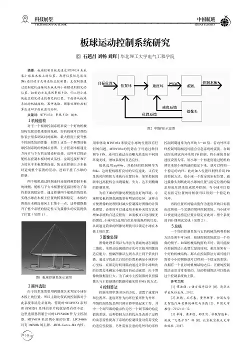
144科技展望TECHNOLOGY OUTLOOK 中国航班CHINA FLIGHTS 板球运动控制系统研究 石越昌 刘畅 刘辉|华北理工大学电气工程学院摘要:板球控制系统是通过MT9V034来采集小球在木板上的位置,再将位置信息通过DMA 通信的方式传送给主控制器,主控制器通过控制舵机连接的木板来将小球摆放到指定的位置。
控制的方式采用串级PID,可以将小球快速且稳定的送到指定的位置。
下面将从板球系统的机械结构、器件选取、图像处理和控制算法这四方面来进行分析。
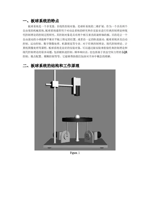
关键词:MT9V034;串级PID;舵机1机械结构对于一个板球控制系统来说一个好的机械结构无疑是很重要的基础,好的机械可以帮助你省去很多调试时的麻烦,最大程度上提升整个控制系统的性能。
如图1这是一个典型的板球控制系统的机械示意图,上方控制木板通过万向节与下方的金属连杆连接,这样可以保证舵机在控制木板时的灵活性。
金属连接杆和下方的水平木板紧密连接,防止在控制上方木板时造成整个装置的晃动,进而干扰了小球的控制。
两个舵机通过控制连杆连接到被控制木板的两侧,舵机与下方木板紧密连接同样为了保持系统的稳定性。
通过控制两个舵机的角度来实现小球在木板上位置的转移和稳定。
木板的四角由木棍连接向上汇集于一点,这样做既提升了整个系统的稳定性又为摄像头的安装提供了位置(见图1)。
图1 板球控制系统示意图2器件选取由于该系统需要用到摄像头来判定小球在木板上的位置,所以主频比较高的控制器对于此系统来说是必要的,传统的STC89C51系列和STM32F1系列的单片机就显得有些不足。
这里选用恩智浦公司的LPC54606作为主控制器,MT9V034来识别小球的位置。
LPC54606具有180MHz 的主频,ARM-Cortex-M4内核,用来驱动MT9V034来锁定小球的位置没有任何的问题。
MT9V034的优势在于可通过软件调节FPS,还可以通过自动曝光来适应不同的环境光线。
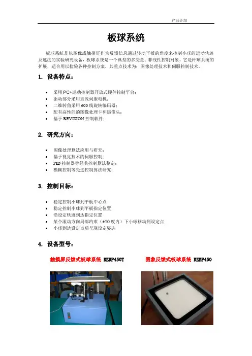
板球系统板球系统是以图像或触摸屏作为反馈信息通过转动平板的角度来控制小球的运动轨迹及速度的实验研究设备,板球系统是一个典型的多变量、非线性控制对象,它是杆球系统的扩展,适合用以检验各种控制方案.其重点技术为:图像处理技术和伺服控制技术。
1.设备特点:∙采用PC+运动控制器开放式硬件控制平台;∙驱动部分采用直流伺服电机;∙二维转角采用600线旋转编码器;∙配有高性能的图像处理卡和摄像头;∙基于REVISION控制软件;2.研究方向:∙图像处理算法应用与研究;∙基于视觉技术的伺服控制;∙PID控制器等经典控制算法整定;∙模糊控制等先进控制算法研究;3.控制目标:∙稳定控制小球到平板中心点∙稳定控制小球到平板指定位置∙沿设定轨迹到达指定位置∙某个滚动方向局部约束(±10度内)下小球移动到设定点∙小球到达设定点后呈现设定姿态4.设备型号:图象反馈式板球系统REBP450触摸屏反馈式板球系统REBP450T5.程序控制界面:5.1 X轴正弦波跟踪5.2 定位跟踪5.3 圆形跟踪控制6. 技术参数:7. 图像采集系统1. 数字摄像头SCOUT scA750-60fc优点: 从VGA 到2兆象素的分辨率,带1394b 接口或者千兆网接口 千兆网的线长可达100米,灵活性极高象素深度达12位,相机内8位数据流无带宽限制 火线和千兆网(GigEVisionTM )的驱动免费 外形小巧,易于集成兼容视觉业的最新标准,包括:GenICam, GigEVision 和EMVA 1288100%的质量检测校准,保证性能以及可靠性规格:尺寸(mm):2. 工业镜头Computar M0814-MP。

快速組裝手冊BESV TRS 2 XCV. 0.0, 20190304內容1.整車箱內容 (2)1.1主內容物 (2)1.2附件箱內容物 (2)2.安裝步驟 (3)2.1龍頭把手 (3)2.2前輪 (4)2.3踏板 (5)2.4座墊座桿 (6)2.5腳架 (6)2.6前燈 (7)2.7前土除 (8)2.8後貨架/土除 (9)2.9伸縮座桿(選配) (10)3.檢查 (14)1.整車箱內容1.1主內容物1.整車車架(含後輪)2.前輪3.附件箱1.2附件箱內容物1. BESV成車說明書-日本(含保固書)2. BESV說明書防竊盜險3. BESV日本保證卡4. 緩衝材5. 緩衝材7. Charger Box(含Charger, Power cord, 充電轉接座)8. 踏板9. 輪輻反光片10. 鈴鐺11. 後反光片/支架12. 儀表14. Shimano說明書2.安裝步驟2.1龍頭, 把手2.1.1調整把手置中後, 角度後掠上揚, 將龍頭與把手依序輪流交互鎖緊至5Nm (龍頭蓋上下間隙需均等)把手角度向後掠上揚間隙均等2.2前輪2.2.1前輪置入前叉後, 插入一快拆輪軸, 轉動螺帽使螺帽外張, 調整快拆把扣緊力道, 確實鎖緊.輪軸螺帽需外張2.2.2調整煞車卡鉗, 使碟盤轉動時, 無受煞車片磨擦d2.3 踏板2.3.1 裝配.“R ” 踏板裝配右側, 以順時針方向確實旋緊“L ” 踏板裝配左側, 以逆時針方向確實旋緊RL2.4座墊座桿2.4.1將座墊依續前後輪流交替鎖緊至6Nm, 鎖緊後, 座墊成水平或前後鎖塊間隙均等狀態.前後間隙均等2.4.2座桿插入部位可抹矽油, 降低磨擦產生異音. 依身高與實際騎乘狀況, 調整座墊高度.取出座桿, 量測插入深度是否足100mm. 否則須更換較長座桿.2.5腳架2.5.1將後腳架上端的鐵片, 放置於車架內側安裝平面平貼, 螺絲由外側穿過車架與腳架鐵片,在車架內側使用尼帽, 將腳架鎖緊(6Nm)Bolts2.6前燈2.6.1移除龍頭前蓋, 更換具有支架鎖點的前蓋, 如圖將龍頭前蓋, Y支架, 前燈鎖固..2.6.2調整前燈角度與位置, 並整理好週圍煞車, 變速, 儀表線.2.6.3連接下管前燈線. 注意白色虛線需與紅線相接2.7前土除2.7.1將土除與土除腳, 用螺絲, 尼帽鎖在一起(M5螺絲8F.7RA38.100, 尼帽8G.12101.851,扭力5Nm)2.7.2將土除腳鎖固在前叉上(M5螺絲8F.7RA38.100, 墊片8H.22201.812, 扭力5Nm)2.7.3將土除鎖固在前叉上橋(M6螺絲8F.8RA6A.100, 墊片8H.22201.A15, 扭力5Nm)2.8後土除2.8後貨架/泥除/反光片2.8.1將反光片與貨架, 用自攻螺絲(反光片配件包)鎖固, (扭力:4Nm)2.8.2使用螺絲(8F.7RY38.100), 墊片(8H.12101.810), 尼帽(8G.12101.851), 將貨架鎖固(扭力:5Nm)) 2.8.3使用螺絲(8F.7RY38.160), 墊片(8H.12101.810), 尼帽(8G.12101.851), 將貨架鎖固(扭力:5Nm) 2.8.4使用螺絲(8F.7RA3A.300), 彈簧墊片(8H.22201.A15), 墊片(8H.12201.A10), 將貨架鎖固在車架勾爪鎖孔上(扭力:6Nm)2.8.5. 使用螺絲(8F.9X138.160), 墊片(8H.12101.810), 配合圓柱墊塊(30.Y28SC.001), 將泥除鎖固在車架上叉橋上(扭力:5Nm)2.8.6.使用螺絲(8F.9X138.160), 墊片(8H.12101.810), 將泥除鎖固在車架下叉橋上(扭力:5Nm)2.9伸縮座桿(選配) (同AM車款裝配方式)2.9.1.購買如下圖之伸縮座桿. 線控機構與上方座桿頭相連接(不可使用底部連接樣式)並準備如下工具2.9.2.將車首入線止栓之固定件取下.2.9.3.將2m的導引線, 由上管後端入線孔穿入在車首左端入線孔, 以LED照入孔內, 車首右端入線孔, 以磁鐵, 鎳子, 將導引線拉出右側入線孔由側面看, 導引線會由上管內部的孔洞, 穿出到下管內,再將導印線從右側入線孔拉出2.9.4.接著將伸縮座桿的黑色外管線, 同樣由上管後端入線孔, 藉由導引線穿入車架內,慢慢的將外管推入車架, 並由車首右側入線孔穿出2.9.5.將導引線抽出車架, 僅留黑色外管在車架內勿移出, 接著將伸縮座桿之內線,同樣由上管後端入線孔, 穿入黑色外管, 一樣由車首右側入線孔穿出.2.9.6.將撥桿鎖固在把手左側, 調整好座桿高度後, 將內線與撥桿, 座桿與座墊鎖緊3.檢察3.1胎壓檢查.3.2煞車, 變速, 鍊條, 功能檢查, 是否連接牢固3.3檢查貨架, 土除, 是否穩固, 並且無歪斜, 以防騎乘危險.3.4插入鑰匙後, 將電池置入, 按下管右側啟動按鈕, 切換左把手之助力模式, 試踩確認馬達運作正常。
目录第一章概述 (1)第二章实训项目 (9)PLC基本技能实操 (9)实训一 PLC认知实训 (9)实训二数码显示控制 (13)实训三抢答器控制 (15)实训四音乐喷泉控制 (18)实训五装配流水线控制 (20)实训六十字路口交通灯控制 (23)实训七水塔水位控制 (26)实训八天塔之光控制 (29)实训九多种液体混合装置控制 (32)实训十加工中心控制 (35)实训十一变频器功能参数设置与操作 (39)实训十二外部开关控制变频调速正反转 (46)实训十三外部模拟量(电压/电流)方式的变频调速控制 (48)实训十四基于PLC控制变频器的多段速运行 (49)附录使用说明书 (52)第一章概述一、PLC的分类及特点可编程控制器简称PLC(Programmable Logic Controller),在1987年国际电工委员会(International Electrical Committee)颁布的PLC标准草案中对PLC做了如下定义:PLC 是一种专门为在工业环境下应用而设计的数字运算操作的电子装置。
它采用可以编制程序的存储器,用来在其内部存储执行逻辑运算、顺序运算、计时、计数和算术运算等操作的指令,并能通过数字式或模拟式的输入和输出,控制各种类型的机械或生产过程。
PLC及其有关的外围设备都应该按易于与工业控制系统形成一个整体,易于扩展其功能的原则而设计。
(一) PLC的分类按产地分,可分为日系、欧美、韩台、大陆等。
其中日系具有代表性的为松下、三菱、欧姆龙、光洋等;欧美系列具有代表性的为西门子、A-B、通用电气、德州仪表等;韩台系列具有代表性的为LG、台达等;大陆系列具有代表性的为合利时、浙江中控等;按点数分,可分为大型机、中型机及小型机等。
大型机一般I/O点数>2048点,具有多CPU,16位/32位处理器,用户存储器容量8~16K;中型机一般I/O点数为256~2048点,单/双CPU,用户存储器容量2~8K;小型机一般I/O点数<256点,单CPU,8位或16位处理器,用户存储器容量4K字以下。

B L生物机能实验系统用户手册TTA standardization office【TTA 5AB- TTAK 08- TTA 2C】BL-420生物机能实验系统用户手册在您使用BL-420生物机能实验系统进行正常实验之前,请您先认真阅读这本《用户手册》,它会循序渐进地帮助您完整地掌握整套BL-420生物机能实验系统的使用方法,特别是教会您熟练地使用为BL-420生物机能实验系统配套的软件——BL-420E+生物信号显示与处理软件来完成各种生物机能实验。
欢迎使用BL-420生物机能实验系统BL-420生物机能实验系统软、硬件安装BL-420E+软件总体介绍BL-420E+软件菜单介绍BL-420E+软件工具条介绍BL-420E+软件其它部分介绍系统维护附录版权:BL-420生物机能实验系统,包括:BL-420E+生物信号显示与处理软件, BL-420硬件、BL-420外置式机箱等,全部版权属于成都泰盟科技有限公司所有。
安全性:BL-420生物机能实验系统通过USB接口与计算机连接,BL-420系统还未获得允许在人体上使用的许可证明,从安全角度出发,本公司只保证该产品用于动物实验,用户使用时必须保证计算机可靠接地,若因计算机接地不良而造成的一切损失,本公司概不负责。
目录§1 欢迎使用BL-420生物机能实验系统.....................................................................§BL-420系统概述............................................................................................... §BL-420系统原理............................................................................................... §BL-420系统特点...............................................................................................§2 BL-420生物机能实验系统软、硬件安装................................................................§硬件安装........................................................................................................... §软件安装...........................................................................................................§ 系统需求.......................................................................................................§ 软件安装 (8)§ USB接口驱动程序安装................................................................................... §3 BL-420E+软件总体介绍 .................................................................................... §软件概述........................................................................................................... §启动及退出软件 ................................................................................................. §主界面.............................................................................................................. §生物信号波形显示窗口........................................................................................§与显示通道相关的快捷功能菜单.......................................................................§区域选择.......................................................................................................§快捷功能菜单命令简介.................................................................................... §数据提取(数据共享)........................................................................................§数据导出.......................................................................................................§数据剪辑.......................................................................................................§图形剪辑.......................................................................................................§图形剪辑窗口介绍..........................................................................................§数据剪辑和图形剪辑的区别 .............................................................................§ 区间测量数据结果的导出 ...............................................................................§4 BL-420E+软件菜单介绍 ....................................................................................§文件菜单........................................................................................................... §设置菜单........................................................................................................... §输入信号菜单 ....................................................................................................§实验项目菜单 (65)§数据处理菜单 .................................................................................................... §工具菜单........................................................................................................... §网络菜单........................................................................................................... §窗口菜单........................................................................................................... §帮助菜单...........................................................................................................§5 BL-420E+软件工具条介绍 .................................................................................§6 BL-420E+软件其它部分介绍 ..............................................................................§时间显示窗口 .................................................................................................... §标尺调节区........................................................................................................ §M ARK标记选择区............................................................................................... §分时复用区.. (119)§控制参数调节区 ..............................................................................................§ 显示参数调节区 .............................................................................................§ 通用信息显示区 .............................................................................................§ 专用信息显示区 ............................................................................................. §滚动条与数据反演功能按钮区. (129)§ 数据选择滚动条 .............................................................................................§ 反演按钮....................................................................................................... §刺激器参数设置 .................................................................................................§ 刺激器调节区.................................................................................................§ 刺激器参数....................................................................................................§ 电刺激属性页.................................................................................................§ 程控属性页.................................................................................................... §状态条..............................................................................................................§7 系统维护.........................................................................................................§系统工作状态检查...............................................................................................§ 直流偏移检查.................................................................................................§ 输入接口检查.................................................................................................§ 记滴功能检查.................................................................................................§ 外触发功能检查 .............................................................................................§ 刺激器检查....................................................................................................§系统故障分析及解决方法 (147)§系统日常保养 .....................................................................................................§8 附录...............................................................................................................§附录一服务指南.................................................................................................§ 公司简介.......................................................................................................§ 服务承诺.......................................................................................................§ 服务信息....................................................................................................... §附录二基本概念................................................................................................. §附录三BL-420E+软件相关文件说明..................................................................... §附录四血流动力学实验模块和心肌细胞动作电位测量中各参数的意义.......................... §附录五实验模块各通道信号类型一览表 (160)§附录六BL-420系统完成的部分典型实验波形.........................................................§1 欢迎使用BL-420生物机能实验系统很高兴您购买了成都泰盟科技有限公司的BL-420生物机能实验系统,祝贺您成为我们公司的又一新用户。
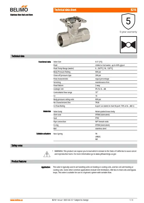
B216•ApplicationStainless Steel Ball and StemTechnical dataFunctional dataValve Size 0.5" [15]Fluidchilled or hot water, up to 60% glycol Fluid Temp Range (water)0...250°F [-18...120°C]Body Pressure Rating 600 psi Close-off pressure ∆ps 200 psiFlow characteristic equal percentage Servicing maintenance-free Flow Pattern 2-way Leakage rate0% for A – AB Controllable flow range 75°Cv16 Body pressure rating note 600 psi No Characterized Disc TRUECv Flow RatingA-port: as stated in chart B-port: 70% of A – AB Cv MaterialsValve body Nickel-plated brass body Stem seal EPDM (lubricated)SeatPTFEPipe connection NPT female ends O-ring EPDM (lubricated)Ballstainless steel Suitable actuatorsNon-SpringTR LRB(X)NRSafety notesWARNING: This product can expose you to lead which is known to the State of California to cause cancer and reproductive harm. For more information go to Product featuresThis valve is typically used in air handling units on heating or cooling coils, and fan coil unit heating or cooling coils. Some other common applications include Unit Ventilators, VAV box re-heat coils and bypass loops. This valve is suitable for use in a hydronic system with variable flow.B216 Flow/Mounting detailsDimensionsDimensional drawingsLRB, LRXA B C D E F H1H29.4" [239] 2.4" [60] 5.6" [141] 5.0" [127] 1.3" [33] 1.3" [33] 1.2" [30] 1.1" [28]TRA B C D E F3.7" [95] 2.4" [60] 5.2" [132]4.6" [117] 1.3" [33] 1.3" [33]TFRB, TFRXA B C D E F6.6" [167] 2.4" [60] 5.5" [139] 4.7" [120] 1.5" [39] 1.5" [39]LFA B C D E F7.9" [200] 2.4" [60] 6.1" [154] 5.5" [140] 1.3" [33] 1.3" [33]ARB N4, ARX N4, NRB N4, NRX N4A B C D E F11.4" [289] 2.4" [60]7.7" [196]7.0" [179] 3.1" [80] 3.1" [80]A B C D E F7.9" [200] 2.4" [60] 6.1" [154] 5.5" [140] 1.3" [33] 1.3" [33]TFRB, TFRXA B C D E F6.6" [167] 2.4" [60] 5.5" [139] 4.7" [120] 1.5" [39] 1.5" [39]ARB N4, ARX N4, NRB N4, NRX N4A B C D E F11.4" [289] 2.4" [60]7.7" [196]7.0" [179] 3.1" [80] 3.1" [80]TR24-SR-T US•••••Modulating, Non-Spring Return, 24 V, for DC 2...10 V or 4...20 mATechnical dataElectrical dataNominal voltageAC/DC 24 V Nominal voltage frequency 50/60 Hz Power consumption in operation 0.5 WTransformer sizing 1 VA (class 2 power source)Electrical Connection Screw terminal (for 26 to 14 GA wire)Overload Protectionelectronic throughout full rotation Functional dataOperating range Y 2...10 VOperating range Y note 4...20 mA w/ ZG-R01 (500 Ω, 1/4 W resistor)Input Impedance 100 kΩ for 2...10 V (0.1 mA), 500 Ω for 4...20 mA Direction of motion motor selectable with switch Manual override push down handle Angle of rotation 90°Running Time (Motor)90 s / 90°Noise level, motor 35 dB(A)Position indicationMechanically, pluggable Safety dataDegree of protection IEC/EN IP40Degree of protection NEMA/UL NEMA 1 UL Enclosure Type 1Agency ListingcULus acc. to UL60730-1A/-2-14, CAN/CSAE60730-1:02, CE acc. to 2014/30/EU and 2014/35/EU; Listed to UL 2043 - suitable for use in air plenums per Section 300.22(c) of the NEC and Section 602.2 of the IMC Quality Standard ISO 9001Ambient temperature -22...122°F [-30...50°C]Storage temperature -40...176°F [-40...80°C]Ambient humidity max. 95% r.H., non-condensing Servicingmaintenance-free WeightWeight0.61 lb [0.28 kg]Safety notesNEMA 4X, 316L stainless steel enclosure.Battery Back Up System for SY(7~10)-110ZS-300 without brackets.NEMA 4X, 304 stainless steel enclosure.MFT95 resistor kit for 4 to 20 mA control applications.Electrical installationINSTALLATION NOTESTR24-SR-T USProvide overload protection and disconnect as required.Actuators may also be powered by 24 VDC.Only connect common to negative (-) leg of control circuits.A 500 Ω resistor (ZG-R01) converts the 4...20 mA control signal to 2...10 V.Actuators are provided with a numbered screw terminal strip instead of a cable.Meets cULus requirements without the need of an electrical ground connection.Warning! Live Electrical Components!During installation, testing, servicing and troubleshooting of this product, it may be necessary to workwith live electrical components. Have a qualified licensed electrician or other individual who has beenproperly trained in handling live electrical components perform these tasks. Failure to follow all electricalsafety precautions when exposed to live electrical components could result in death or serious injury.2...10 V / 4...20 mA Control。
Installation & Maintenance Manual1. USE:1.1 Life of valve can be maximized if the valve is used within the rated range, in accordance with pressure,temperature, and corrosion data.2. MANUALOPERATION:2.1 To open or close the valve, turn the handle ¼ turn (90 degrees).A. Valve in Open Position – the handle is in parallel (in-line) with the valve or pipeline.B. Valve in Closed Position – the handle is perpendicular (crossed) with the valve or pipeline.3. DISASSEMBLING & CLEANING THE VALVE:3.1 Ball valves can trap fluids in ball cavity when it is in closed position.3.2 If the valve has been used in hazardous media, it must be decontaminated before disassembly.A. Relieve the line pressure.B. Place valve in half-open position and flush the line to remove any hazardous material from valve.C. All persons involved in the removal and disassembly of the valve should wear the proper protective clothing, suchas face shield, glove, apron, etc.4. REPLACING THE THRUST WASHER, PACKING, AND SEATS4.1 Before replacing the stem seal and the packing, the pipeline must be de-pressurized.4.2 Take-off the valve from the pipeline.4.3 Place valve in its’ fully open position.4.4 Take-offendcap.4.5 Close the valve and remove the seat, body seals and ball.4.6 Remove the valve stem nut, handle, gland nut and remove the valve stem through the body cavity.4.7 Remove the stem trust washer from the stem cavity.4.8 Examine all metallic sealing surfaces such as ball, stem and end cap for damage, if the ball or stem is excessivelydamaged, ball and stem need to be replaced.5. RE-ASSEMBLINGHaving assured that all critical surfaces and components have been inspected, cleaned and or replaced, re-assemble can begin.5.1 Place new stem seal on stem and install the stem.5.2 Install new gland packing, bushing,gland bush, belleville washerand stem nut5.3 Tighten stem nut to torque specification in Table 1.5.4 Lightly lubricate seats and body seals using a lubricant.5.5 Re-install end cap. Valve Size Stem Nut Torque (In-Lbs.)½” ~ 3/4” 901” 120 1-1/2” 225 2” ~ 2-1/2” 3103” 400 Table 1Installation & Maintenance ManualA-T Controls product, when properly selected, is designed to perform its intended function safely during its useful life. However, the purchaser or user of A-T Controls products should be aware that A-T Controls products might be used in numerous applications under a wide variety of industrial service conditions. Although A-T Controls can provide general guidelines, it cannot provide specific data and warnings for all possible applications. The purchaser / user must therefore assume the ultimate responsibility for the proper sizing and selection, installation, operation, and maintenance of A-T Controls products. The user should read and understand the installation operation maintenance (IOM) instructions included with the product, and train its employees and contractors in the safe use of A-T Controls products in connection with the specific application.While the information and specifications contained in this literature are believed to be accurate, they are supplied for informative purposes only. Because A-T Controls is continually improving and upgrading its product design, the specifications, dimensions and information contained in this literature are subject to change without notice. Should any question arise concerning these specifications, the purchaser/user should contact A-T Controls.For product specifications go to /A-T Controls, Inc. • 9955 International Boulevard, Cincinnati, OH 45246 • Phone: (513) 530-5175 • Fax: (513) 247-5462 • 。
Manual de instruccionesVálvula de bola de uso general GP-Vo previstoLa válvula de bola serie BX está diseñadaexclusivamente para cerrar y conducir los fluidos dentro del rango de presión y temperatura permitidos en los sistemas de tuberías en los que está instalado. La vida útil máxima es de 25 años.2. Con respecto a este documento2.1. Abreviaturas PN Presión Nominal DNDiámetro Nominal2.2. Instrucciones de seguridad y advertenciasADVERTENCIA PRECAUCIÓN3.Seguridad y responsabilidad•La válvula de bola BX solo se puede usar para su propósito previsto (ver 1. Uso previsto).•Observe siempre las especificaciones, precauciones e instrucciones del producto.•Nunca use un producto dañado o defectuoso.•Asegúrese de que el sistema de tuberías se haya instalado profesionalmente y se le haya dado servicioregularmente.•Los productos y equipos deben ser instalados solo por personas que tengan la capacitación, el conocimiento o la experiencia requeridos.•Capacite regularmente al personal en todas laspreguntas relevantes relacionadas con la seguridad en el trabajo y la protección del medio ambiente.4.Transporte y almacenamiento•Transporte y / o almacene el producto en su embalaje original sin abrir.•Almacene el producto en un lugar fresco y seco, lejos de la luz solar directa. Proteja el producto del polvo y la suciedad, las radiaciones térmicas y UV.•Asegúrese de que el producto no haya sido dañado ni por influencias mecánicas ni térmicas.5.Instalación•Retire la válvula de bola de su embalaje original inmediatamente antes de la instalación.•Asegúrese de que la presión nominal, el tipo de conexión y las dimensiones correspondan a las condiciones de funcionamiento.•Haga una prueba de funcionamiento: cierre la válvula de bola y ábrala nuevamente. Las válvulas de bola que no funcionan correctamente no deben instalarse.•Siempre instale la válvula en la posición abierta.•Asegúrese de que la válvula de bola esté alineada con la tubería para que la válvula se mantenga libre de tensión mecánica.•Desenrosque los extremos de unión (componentes n.1 y 2) de la válvula.•Instale la válvula, vea las figuras a - d.•Siga las instrucciones específicas de unión para soldadura solvente y conexión roscada.abcdPRECAUCIÓNConexión de soldadura solvente: mientras cementa las conexiones a los extremos de la tubería, manténgalas separadas del cuerpo de la válvula.Conecte el cuerpo de la válvula solo después de que el cemento solvente esté seco.Esto evitará que el cemento solvente dañe el cuerpo y las piezas de trabajo.PRECAUCIÓNEnrosque solo a mano, sin el uso de herramientas adicionales.El uso de herramientas adicionales puede dañar las tuercas o su rosca.Implemente abajo PRECAUCIÓNLa presión de prueba deun conjuntono puedeexceder 1.1xPN. El componente con la PN más baja determina la presión de prueba máxima permitida en la sección de prueba.•Verifique que todas las válvulas estén en la posición requerida (abierta o cerrada).•Llene el sistema de tuberías y desaírelo cuidadosamente.•Verifique que las válvulas y los conectores no tengan fugas.•Después de la prueba de fugas: retire el fluido de prueba.•***********************•Tel:(800)343-3618,(781)321-540916.Desmontaje7.MantenimientoSe deben tener en cuenta las siguientes medidas:•Inspección periódica para asegurarse de que no hayanfugas.•Para válvulas de bola que se mantienenpermanentemente en la misma posición: 1 o 2 veces alaño, realice una prueba de funcionamiento para verificarla capacidad de servicio.•Para operaciones de control frecuentes (por ejemplo,válvulas automáticas) o debido a un ataque químico almaterial de sellado: verifique si puede ser necesarioreemplazar las piezas internas. Para este propósito, laválvula debe retirarse del sistema de tuberías (ver 6.Desmontaje). Ver tabla de componentes para repuestos•Para ensamblar los componentes y reemplazar lossellos, vea las figuras i - r.•Apriete las tuercas (2) para que la bola se muevacómodamente.Declaración de conformidadEl fabricante declara, de conformidad con lanorma armonizada ISO 16135: 2001, que lasválvulas de bola son componentes que soportanpresión en el sentido de la Directiva 2014/68/UEsobre equipos a presión y que cumplen losrequisitos correspondientes a las válvulas comose indica en esta directriz (solo válvulas mayoresde DN 25).03/09/2020Componentese fg h* Partes de repuesto disponiblesFuerza de torsióni l m no p q r•***********************•Tel:(800)343-3618,(781)321-54092 I Manual de instrucciones Válvula de bola de uso general GP-V•Alivie completamente la presión en las tuberías.•Vacíe completamente y enjuague la tubería.Preste atención a los posibles residuos.•Retire la válvula de la tubería desenroscando lastuercas.•Abra parcialmente la válvula desmontada(posición de 45°) y deje que drene en posiciónvertical.•Para desmontar la válvula, vea las figuras e - h.。
Bulletin HY14-2704-B1/USSeries V16Directional ControlValvesSpecificationsEffective:July 1, 2003Supersedes:Cat. No. GPD-1435 dated 4/98DescriptionParker's Series V16 sectional directional control valvesprovide proportioning-type, pressure compensated operationfor closed center and load sensing systems. A variety ofspool variations, spool actuator options, and relief valvecartridges are available to customize the valve to yourparticular applications.Features•Individual proportioning-type (post) pressure compensation.•Precise metering spools offering compensated flows up to15 GPM (57 lpm).•Continuous system operating pressures to 3,500 PSI.(work port pressures to 5,000 PSI)•Utilized many common components such as relief valves, spoolpositioners and handles with Series V10 and V11.•3-way, 4-way, and 4-way float operation.•Load sense bleed-off orifice plug.•Manual or remote hydraulic or electric solenoid operation.•Single handle or dual function mechanical joystick control ofmanual sections.•Port reliefs and anti-cavitation checks standard.ParkerConsult the factory with specific flow requirements.(ParkerPost Pressure Compensated Valve Assembly FormV16 Ordering InformationOffer of SaleThe items described in this document and other documents or descriptions provided by Parker Hannifin Corporation, its subsidiaries and its authorized distributors are hereby offered for sale at prices to be established by Parker Hannifin Corporation, its subsidiaries and its authorized distributors. This offer and its acceptance by any customer ("Buyer") shall be governed by all of the following Terms and Conditions. Buyer’s order for any such items,when communicated to Parker Hannifin Corporation, its subsidiary or an authorized distributor ("Seller") verbally or in writing, shall constitute acceptance of this offer.paid by Buyer. Unless otherwise agreed, Seller shall have the right to alter,discard or otherwise dispose of any special tooling or other property in its sole discretion at any time.8. Buyer’s Property: Any designs, tools, patterns, materials, drawings,confidential information or equipment furnished by Buyer or any other items which become Buyer’s property, may be considered obsolete and may be destroyed by Seller after two (2) consecutive years have elapsed without Buyer placing an order for the items which are manufactured using such property, Seller shall not be responsible for any loss or damage to such property while it is in Seller’s possession or control.9. Taxes: Unless otherwise indicated on the face hereof, all prices and charges are exclusive of excise, sales, use, property, occupational or like taxes which may be imposed by any taxing authority upon the manufac-ture, sale or delivery of the items sold hereunder. If any such taxes must be paid by Seller or if Seller is liable for the collection of such tax, the amount thereof shall be in addition to the amounts for the items sold. Buyer agrees to pay all such taxes or to reimburse Seller therefore upon receipt of its invoice. If Buyer claims exemption from any sales, use or other tax imposed by any taxing authority, Buyer shall save Seller harmless from and against any such tax, together with any interest or penalties thereon which may be assessed if the items are held to be taxable.10. Indemnity For Infringement of Intellectual Property Rights: Seller shall have no liability for infringement of any patents, trademarks, copy-rights, trade dress, trade secrets or similar rights except as provided in this Part 10. Seller will defend and indemnify Buyer against allegations of infringement of U.S. Patents, U.S. Trademarks, copyrights, trade dress and trade secrets (hereinafter ‘Intellectual Property Rights’). Seller will defend at its expense and will pay the cost of any settlement or damages awarded in an action brought against Buyer based on an allegation that an item sold pursuant to this contract infringes the Intellectual Property Rights of a third party. Seller’s obligation to defend and indemnify Buyer is contingent on Buyer notifying Seller within ten (10) days after Buyer becomes aware of such allegations of infringement, and Seller having sole control over the defense of any allegations or actions including all negotiations for settlement or compromise. If an item sold hereunder is subject to a claim that it infringes the Intellectual Property Rights of a third party, Seller may, at its sole expense and option, procure for Buyer the right to continue using said item, replace or modify said item so as to make it noninfringing, or offer to accept return of said item and return the purchase price less a reasonable allowance for depreciation. Notwith-standing the foregoing, Seller shall have no liability for claims of infringe-ment based on information provided by Buyer, or directed to items delivered hereunder for which the designs are specified in whole or part by Buyer, or infringements resulting from the modification, combination or use in a system of any item sold hereunder. The foregoing provisions of this Part 10 shall constitute Seller’s sole and exclusive liability and Buyer’s sole and exclusive remedy for infringement of Intellectual Property Rights.If a claim is based on information provided by Buyer or if the design for an item delivered hereunder is specified in whole or in part by Buyer, Buyer shall defend and indemnify Seller for all costs, expenses or judgments resulting from any claim that such item infringes any patent, trademark,copyright, trade dress, trade secret or any similar right.11. Force Majeure: Seller does not assume the risk of and shall not be liable for delay or failure to perform any of Seller’s obligations by reason of circumstances beyond the reasonable control of Seller (hereinafter ‘Events of Force Majeure’). Events of Force Majeure shall include without limitation, accidents, acts of God, strikes or labor disputes, acts, laws,rules or regulations of any government or government agency, fires,floods, delays or failures in delivery of carriers or suppliers, shortages of materials and any other cause beyond Seller’s control.12. Entire Agreement/Governing Law: The terms and conditions set forth herein, together with any amendments, modifications and any different terms or conditions expressly accepted by Seller in writing, shall constitute the entire Agreement concerning the items sold, and there are no oral or other representations or agreements which pertain thereto. This Agreement shall be governed in all respects by the law of the State of Ohio.No actions arising out of the sale of the items sold hereunder or this Agreement may be brought by either party more than two (2) years after the cause of action accrues.9/91-P1. Terms and Conditions of Sale: All descriptions, quotations, propos-als, offers, acknowledgments, acceptances and sales of Seller’s products are subject to and shall be governed exclusively by the terms and conditions stated herein. Buyer’s acceptance of any offer to sell is limited to these terms and conditions. Any terms or conditions in addition to, or inconsistent with those stated herein, proposed by Buyer in any accep-tance of an offer by Seller, are hereby objected to. No such additional,different or inconsistent terms and conditions shall become part of the contract between Buyer and Seller unless expressly accepted in writing by Seller. Seller’s acceptance of any offer to purchase by Buyer is expressly conditional upon Buyer’s assent to all the terms and conditions stated herein, including any terms in addition to, or inconsistent with those contained in Buyer’s offer, Acceptance of Seller’s products shall in all events constitute such assent.2. Payment: Payment shall be made by Buyer net 30 days from the date of delivery of the items purchased hereunder. Amounts not timely paid shall bear interest at the maximum rate permitted by law for each month or portion thereof that the Buyer is late in making payment. Any claims by Buyer for omissions or shortages in a shipment shall be waived unless Seller receives notice thereof within 30 days after Buyer’s receipt of the shipment.3. Delivery: Unless otherwise provided on the face hereof, delivery shall be made F.O.B. Seller’s plant. Regardless of the method of delivery,however, risk of loss shall pass to Buyer upon Seller’s delivery to a carrier.Any delivery dates shown are approximate only and Seller shall have no liability for any delays in delivery.4. Warranty: Seller warrants that the items sold hereunder shall be free from defects in material or workmanship for a period of 18 months from date of shipment from Parker Hannifin Corporation. THIS WARRANTY COMPRISES THE SOLE AND ENTIRE WARRANTY PERTAINING TO ITEMS PROVIDED HEREUNDER. SELLER MAKES NO OTHER WAR-RANTY, GUARANTEE, OR REPRESENTATION OF ANY KIND WHAT-SOEVER. ALL OTHER WARRANTIES, INCLUDING BUT NOT LIM-ITED TO, MERCHANTABILITY AND FITNESS FOR PURPOSE,WHETHER EXPRESS, IMPLIED, OR ARISING BY OPERATION OF LAW, TRADE USAGE, OR COURSE OF DEALING ARE HEREBY DISCLAIMED. NOTWITHSTANDING THE FOREGOING, THERE ARE NO WARRANTIES WHATSOEVER ON ITEMS BUILT OR ACQUIRED WHOLLY OR PARTIALLY, TO BUYER’S DESIGNS OR SPECIFICA-TIONS.5. Limitation Of Remedy: SELLER’S LIABILITY ARISING FROM OR IN ANY WAY CONNECTED WITH THE ITEMS SOLD OR THIS CON-TRACT SHALL BE LIMITED EXCLUSIVELY TO REPAIR OR RE-PLACEMENT OF THE ITEMS SOLD OR REFUND OF THE PURCHASE PRICE PAID BY BUYER, AT SELLER’S SOLE OPTION. IN NO EVENT SHALL SELLER BE LIABLE FOR ANY INCIDENTAL, CONSEQUEN-TIAL OR SPECIAL DAMAGES OF ANY KIND OR NATURE WHATSO-EVER, INCLUDING BUT NOT LIMITED TO LOST PROFITS ARISING FROM OR IN ANY WAY CONNECTED WITH THIS AGREEMENT OR ITEMS SOLD HEREUNDER, WHETHER ALLEGED TO ARISE FROM BREACH OF CONTRACT, EXPRESS OR IMPLIED WARRANTY, OR IN TORT, INCLUDING WITHOUT LIMITATION, NEGLIGENCE, FAILURE TO WARN OR STRICT LIABILITY.6. Changes, Reschedules and Cancellations: Buyer may request to modify the designs or specifications for the items sold hereunder as well as the quantities and delivery dates thereof, or may request to cancel all or part of this order, however, no such requested modification or cancel-lation shall become part of the contract between Buyer and Seller unless accepted by Seller in a written amendment to this Agreement. Accep-tance of any such requested modification or cancellation shall be at Seller’s discretion, and shall be upon such terms and conditions as Seller may require.7. Special Tooling: A tooling charge may be imposed for any special tooling, including without limitation, dies, fixtures, molds and patterns,acquired to manufacture items sold pursuant to this contract. Such special tooling shall be and remain Seller’s property notwithstanding payment of any charges by Buyer. In no event will Buyer acquire any interest in apparatus belonging to Seller which is utilized in the manufacture of the items sold hereunder, even if such apparatus has been specially con-verted or adapted for such manufacture and notwithstanding any chargesBulletin HY14-2704-B1/US,3C, 3/04, PHDParker Hannifin CorporationHydraulic Valve Division 520 Ternes AvenueElyria, Ohio, 44035 USA Tel:(440) 366-5200Fax:(440) 366-5253Copyright 2002, Parker Hannifin Corporation, All Rights ReservedFAILURE OR IMPROPER SELECTION OR IMPROPER USE OF THE PRODUCTS AND/OR SYSTEMS DESCRIBED HEREIN OR RELATED ITEMS CAN CAUSE DEATH, PERSONAL INJURY AND PROPERTY DAMAGE.This document and other information from Parker Hannifin Corporation, its subsidiaries and authorized distributors provide product and/or system options for further investigation by users having technical expertise.It is important that you analyze all aspects of your application and review the information concerning the product or system in the current product catalog. Due to the variety of operating conditions and applications for these products or systems, the user, through its own analysis and testing, is solely responsible for making the final selection of the products and systems and assuring that all performance, safety and warning requirements of the application are met.The products described herein, including without limitation, product features, specifications, designs, availability and pricing, are subject to change by Parker Hannifin Corporation and its subsidiaries at any time without notice.WARNINGThe items described in this document are hereby offered for sale by Parker Hannifin Corporation, its subsidiaries or its authorized distributors. This offer and its acceptance are governed by the provisions stated in the "Offer of Sale".Offer of Sale。
This document is provided for use and guidance of engineering personnel engaged in the installation or application of STORM data entry products manufactured by Keymat Technology Ltd. Please be advised that all information, data, and illustrations contained within this document remain theUSA OFFICE UK OFFICE 364 Pennsylvania Avenue, Suite 202 14 Bentinck Court, Glen Ellyn Bentinck Road, Illinois 60137 West Drayton UB7 7RQ USA ENGLAND Tel +1 (630) 469 2981 Tel +44 (1895) 431421 email:This document is provided for use and guidance of engineering personnel engaged in the installation or application of STORM data entry products manufactured by Keymat Technology Ltd. Please be advised that all information, data, and illustrations contained within this document remain the Table of ContentsSection PageSection 1. Overview of Range 3 Section 2. Configuration Settings 3 Section 3. Specifications, Ratings and Performance 4 Section 4. Connectors and Connections 5 ConnectionsPinout DetailsSection 5: Frequently Asked Questions 8 Section 6. Servicing9Section 7. Spares Ordering 91. Overview of RangeThe Storm Trackball range (as fitted to the Storm 2200 keyboard) comprises a number of rugged Trackballs utilising 38mm (1.5") balls. The units are designed for public access applications and are available with either a black phenolic resin ball or a specially treated steel ball. Both types are available with either- auto-configuring PS2/USB output (standard product), or- Microsoft compatible serial (RS232) output (to special order only).Each unit has a self-adjusting seal around the ball which affords the unit an IP65 rating whilst ensuring that the ball tracks smoothly and accurately under all operating conditions.All units are further protected by a stainless steel ‘anti-vandal’ plate which transmits shock loads (for example, due to abuse) directly to the stainless steel keyboard fascia, thus preventing damage to the trackball assembly.2. Configuration settingsThere are no user-selectable configuration settings on the Trackball units.This document is provided for use and guidance of engineering personnel engaged in the installation or application of STORM data entry products manufactured by Keymat Technology Ltd. Please be advised that all information, data, and illustrations contained within this document remain theThis document is provided for use and guidance of engineering personnel engaged in the installation or application of STORM data entry products manufactured by Keymat Technology Ltd. Please be advised that all information, data, and illustrations contained within this document remain the3. Specifications.MechanicalBall dimensions 38.1mm ±0.05mmTracking force 50g nominal- any direction (tangential to ball) Ball speed 250 rpm maximumSeal material PTFE with low friction fillBall material Phenolic resin or Surface-treated steelBody materialPolymer Flammability UL94 - V-0 Bezel material Stainless steel Shaft materialStainless steel Anti-vandal plate material Stainless steelElectricalSupply voltage 5.0V dc ±10%Resolution 150 pulses/ball revolution 600 counts/ball revolution Switch debounce 30ms rising and falling Supply current (protocol) 15mA maximum Supply current (USB Suspend Mode) 450µA maximum Button pullup resistors 7k Ω nominal Minimum output high voltage Data, Clk 4.5V Maximum output low voltage Data, Clk 0.8VEnvironmentalStorage temperature -25°C to +85°C Operating temperature 0°C to +70°C Humidity 95% rh, non-condensing, maximum Static ball load 1000N maximumSealing IP65 (static), IP54 (rotating) Shock ball load 10J maximum Lifetime 10 million ball revolutions minimumThis document is provided for use and guidance of engineering personnel engaged in the installation or application of STORM data entry products manufactured by Keymat Technology Ltd. Please be advised that all information, data, and illustrations contained within this document remain the4. Connection FormatsAll units are fitted with two Molex 5046 headers to allow connection to the associated buttons and also to the host computer. Cables are normally ordered separately to allow the user choice of interface. (See Section 7 for ordering details). Note that earlier models can be factory configured with both buttons as left click. In later versions this feature is user selectable with a jumper between the two Molex headers.P1 is the input connector for the buttons (6-way) and is always fitted. P3 is the output connector for USB and PS/2 protocols (6-way).P4 is the RS232 output connection for Microsoft serial protocol (6-way).Either P3 or P4 are fitted, never both.Table 1 shows the connector pin-out details:Pin P1 Function P3 FunctionP4 Function 1 0V D-/ DATA Tx 2 Button 1(L) D+/ CLK Rx3 0VTEST RTS 4 Button3 (R) +5V +5V 5 0V 0V 0V 6 Button 2(M)N.C.DTRTable 1: Connector detailsPlease note that the TEST input is reserved for factory test only. On no account should a connection be made to this terminal.The Button inputs are pulled high within the unit to the 5V power supply via approximately 7k Ω. Both rising and falling edges of this signal are debounced for 30ms.P3 OR P4 P1Since Trackballs are classified as Human Input Devices (HID) by the USB organisation, they implement the low-speed USB specification. Therefore it is not necessary to shield the cable carrying the D+ and D- signals, although it is highly recomended that you do so. In addition, it is recommended that the systems integrator follows USB guidelines on wire gauge and twisted pairs.In serial (RS232) modes, both RTS and DTR must be connected for the unit to operate correctly when no 5V supply is present. It is not sufficient to just connect RTS, unless the external 5V supply is present. The following diagrams show the connection details for the corresponding connectors to the computer :USB4-pin type- A plug, viewed looking into pins.PS/26-pin plug, viewed looking into pins.This document is provided for use and guidance of engineering personnel engaged in the installation or application of STORM data entry products manufactured by Keymat Technology Ltd. Please be advised that all information, data, and illustrations contained within this document remain theRS232 (COM PORT)9-pin sub-D socket, viewed looking into pins.Pins with no legend are not connected.This document is provided for use and guidance of engineering personnel engaged in the installation or application of STORM data entry products manufactured by Keymat Technology Ltd. Please be advised that all information, data, and illustrations contained within this document remain the5. Frequently Asked QuestionsQ. How are the various protocols selected on multi-protocol Trackballs?A. The unit automatically selects either USB or PS/2 protocols on power-up without setting any DIP switches.Q. My Trackball wasn’t supplied with a driver disk. Is this correct?A. Yes, our products are designed to work with resident drivers and do not require any further software to be loaded.Q. I have connected my Trackball to a USB port but it does not function. Why is this?A. Ensure you do not have either Windows 3.1 / 95 or Windows NT operating systems- none of which support USB even if your computer has the necessary sockets.If you have Windows 3.1 / 95 installed, consider an upgrade to Windows 98. If you have Windows NT4 installed, consider upgrading to Windows 2000.Q. Is any maintenance or adjustment required through the life of the product?A. No, other than periodic cleaning with a clean, lint-free cloth, no maintenance is required. The electronics are calibrated for life facture and require no maintenance.Q. What happens if liquid is dragged around the ball in usage ?A. The rear of the trackball incorporates a collar so that in the event of this happening any liquid is channeled away from the trackball electronics.Q. I have purchased a standard unit and am installing it in a kiosk where the right button function must not be accessible to the user. How can I disable the right button ?A. Remove the connection going to Pin 4 on connector P1.This document is provided for use and guidance of engineering personnel engaged in the installation or application of STORM data entry products manufactured by Keymat Technology Ltd. Please be advised that all information, data, and illustrations contained within this document remain theThis document is provided for use and guidance of engineering personnel engaged in the installation or application of STORM data entry products manufactured by Keymat Technology Ltd. Please be advised that all information, data, and illustrations contained within this document remain the6. ServicingNo routine servicing is necessary to the trackball product. The seal around the ball offers a high level of protection to the internal mechanism and circuitry, making routine cleaning unnecessary.In high-use applications the user may occasionally notice a slightly ‘lumpy’ feel to the ball. This is invariably a small build-up of debris between the shafts and ball and may be removed by gently pushing against the ball whilst rotating it. This has the effect of crushing the debris and moving it off the run-line between the ball and shafts. The unit will then behave normally.If the trackball requires cleaning in-situ, this can be carried out using a clean, lint-free cloth. Do not use solvents, abrasives or other cleaning agents.If the trackball has to be replaced, follow the following procedure :1/ Remove both cable connections.2/ Undo 4 M3 nuts and washers from the back of the trackerball unit.3/ Remove the anti-vandal plate.4/ Lift the entire trackerball unit and sealing gasket off the back of the keyboard.5/ Fit new sealing gasket and trackerball unit.6/ Refit nuts, torque to 50Ncm.7. Spares OrderingThe following parts are available to order from your Storm distributorDescription Order CodeCable 2.5m PS2 2200-00200[x] Cable 2.5m USB 2200-00300[x]Trackerball Unit PS2/USB Black Phenolic Ball 2210-00020[x] Trackerball Unit PS2/USB Stainless Steel Ball 2210-00030[x]。
优利德科技(中国)股份有限公司NeptuneLab 3.5 系统使用文档V05张恩豪2022-4-6版权所有© 2022 优利德科技(中国)股份有限公司保留一切权利。
非经本公司书面许可,任何单位和个人不得擅自摘抄、复制本文档内容的部分或全部,并不得以任何形式传播。
声明:本公司产品受中国及其它国家和地区的专利(包括已取得的和正在申请的专利)保护。
本公司保留改变规格及价格的权利。
本手册提供的信息取代以往出版的所有资料。
本手册提供的信息如有变更,恕不另行通知。
对于本手册可能包含的错误,或因手册所提供的信息及演绎的功能以及因使用本手册而导致的任何偶然或继发的损失,本公司概不负责。
未经本公司事先书面许可,不得影印、复制或改编本手册的任何部分。
所有基于平台的实验结果计算,请根据实验模块器件的实际测量参数进行计算。
由于产品版本升级或其他原因,本文档内容会不定期进行更新。
除非另有约定,本文档仅作为使用指导,本文档中的所有陈述、信息和建议不构成任何明示或暗示的担保。
优利德科技(中国)股份有限公司地址:广东省东莞市松山湖园区工业北一路6号邮编:523000网址:电子邮箱:********************.cn电话:400-876 7822修改记录文档版本发布日期修改说明修订人V01 2020-11-11 NeptuneLab3.0第一次修正版本发布张恩豪V02 2021-01-07 NeptuneLab3.0第二次修正版本发布张恩豪V03 2021-06-15 NeptuneLab3.0第三次修正版本发布张恩豪V04 2021-11-15 NeptuneLab3.0第四次修正版本发布张恩豪V05 2022-04-06 3.5版本新功能添加张恩豪目录NeptuneLab3.0系统使用文档 (6)一、校园管理 (7)1. 学校管理 (7)2. 校区管理 (7)3. 学院管理 (8)4. 学科管理 (8)5. 班级管理 (8)二、账户管理 (9)1. 学生管理 (9)2. 导师管理 (11)3. 教务管理员 (11)4. 系统管理员 (11)5. 角色&权限管理 (12)三、排课管理 (14)1. 课程设置 (14)2. 学期管理 (16)3. 课时配置 (16)4. 预约条款 (17)a. 通用条款 (17)b. 预约排课条款 (17)5. 课程表管理 (19)6. 选课记录 (20)四、资源空间 (21)1. 校内云 (21)a. 模板库 (21)b. 题库 (23)c. 文库 (23)2. 我的资源 (24)a. 我的模板 (24)b. 题库 (24)c. 我的文档 (25)d. 用量 (25)3. 通用配置 (25)a. 通用指标点* (25)b. 模板组件管理 (27)五、实验室管理 (27)1. 实验室管理 (27)2. 一卡通管理 (28)3. 人脸管理 (29)4. 指纹管理 (30)5. 物联网外设 (30)六、我的课程 (31)1. 电子教室 (31)2. 已结束 (35)3. 课程表 (36)七、学生报告 (36)1. 实验报告 (36)2. 全部报告 (38)3. 公开报告 (39)4. 统计分析 (39)5. 达成度报告 (40)八、预约管理 (41)1. 实验室开放管理* (41)2. 实验室开放预约 (42)a. 待审核预约 (42)b. 全部预约 (43)c. 开放预约条款 (44)d. 开放预约条款 (44)e. 可预约学生清单 (44)九、测量工作站 (44)1. 万用表采集测量 (45)2. 毫伏表采集测量 (45)3. 信号源采集测量 (45)4. 示波器采集测量 (45)5. 电源采集测量 (46)十、资产管理 (47)1. 全部资产 (47)十一、虚实电路控制 (47)1. 硬件描述(非菜单) (47)2. 虚实电路控制 (50)2.1 连接模式选择 (50)2.2 电路绘制 (51)备注1:登录说明 (53)备注2:新的系统需要做些什么 (54)备注3:导师如何开始上课 (54)备注4:学生如何通过系统参与到课程 (55)备注5:测量组件如何使用 (58)备注6:预约实验室(使用门禁、工位电源)管理流程 (60)NeptuneLab3.5系统使用文档文中所有截图的“*”是注意事项或者必填项。