电池管理系统安装使用说明书
- 格式:pdf
- 大小:187.03 KB
- 文档页数:19
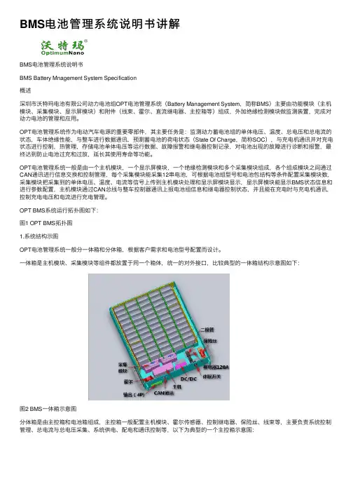
BMS电池管理系统说明书讲解BMS电池管理系统说明书BMS Battery Mnagement System Specification概述深圳市沃特玛电池有限公司动⼒电池组OPT电池管理系统(Battery Management System,简称BMS)主要由功能模块(主机模块、采集模块、显⽰屏模块)和附件(线束、霍尔、直流继电器、主控箱等)组成,外加绝缘检测模块做监测装置,完成对动⼒电池的管理和应⽤。
OPT电池管理系统作为电动汽车电源的重要零部件,其主要任务是:监测动⼒蓄电池组的单体电压、温度、总电压和总电流的状态,车体绝缘性能,与整车进⾏数据通讯,预测蓄电池的荷电状态(State Of Charge,简称SOC),与充电机通讯并对充电状态进⾏控制,热管理,存储电池单体电压等运⾏数据、故障报警和继电器控制记录,对电池出现的故障进⾏诊断和报警,最终达到防⽌电池过充和过放,延长其使⽤寿命等功能。
OPT电池管理系统⼀般是由⼀个主机模块,⼀个显⽰屏模块,⼀个绝缘检测模块和多个采集模块组成,各个组成模块之间通过CAN通讯进⾏信息交换和控制管理,每个采集模块能采集12串电池,可根据电池组型号和电池包结构等条件配置采集模块数,采集模块把采集到的单体电压、温度、电流等信号上传到主机模块处理和显⽰屏模块显⽰,显⽰屏模块能显⽰BMS状态信息和进⾏参数配置,主机模块通过CAN总线与整车控制器通讯上报电池组信息和继电器控制状态,并且能在充电时与充电机通讯,控制充电电压和电流进⾏充电管理。
OPT BMS系统运⾏拓扑图如下:图1 OPT BMS拓扑图1.系统结构⽰图OPT电池管理系统⼀般分⼀体箱和分体箱,根据客户需求和电池型号配置⽽设计。
⼀体箱是主机模块、采集模块等组件都放置于同⼀个箱体,统⼀的对外接⼝,⽐较典型的⼀体箱结构⽰意图如下:图2 BMS⼀体箱⽰意图分体箱是由主控箱和电池箱组成,主控箱⼀般配置主机模块、霍尔传感器、控制继电器、保险丝、线束等,主要负责系统控制管理、总电流与总电压采集、系统供电、配电和通讯控制等,以下为典型的⼀个主控箱⽰意图:图3 BMS主控箱结构⽰意图电池箱是根据客户需求和电池型号,配置不同的采集模块和风扇数量,实现采集单体电压、温度并通过CAN总线上报主机,并能进⾏热管理,其中典型的⼀个电池箱结构⽰意图如下:动⼒线接⼝通讯⼝采⽤螺母固定,从车箱底部锁螺丝上来图4 OPT BMS电池箱结构⽰意图2.OPT BMS各部件功能及其接⼝定义3.1 OPT BMS外形尺⼨1、主机模块:130*110*39mm2、采集模块:113mm*96mm*43mm3、GPRS&数据存储上传模块:未定4、CAN盒125*82*27mm5、绝缘检测模块:165.0*80.0*26.5mm6、显⽰模块:160mm*96mm*42mm3.2 OPT BMS主机模块3.2.1 主机模块功能指标Ⅰ. 电池组电压计算与控制接收采集模块上传的电池组的所有单体电压,计算电池总电压并能够选出电池组的最⾼单节电池电压及序号和最低单节电池电压及序号,并能在显⽰屏模块指定位置显⽰,同时可以通过专⽤CAN ⼝上传到汽车仪表总线.Ⅱ. 电池组总电流检测和计算接收主控本⾝或采集模块上传的电池电流采集,根据设定的霍尔传感器额定参数,计算电池组总电流,并能在显⽰屏模块指定位置显⽰。
48V-5.12kWh家用储能电源Household energy storage power supply使用说明手册Instruction manual科技有限公司Electronic Technology Co., Ltd尊敬的用户:首先感谢您选用xx家用储能系统电源,xxxx电子科技有限公司是一家从锂动力电池成套产品研发、生产和销售的股份制高新技术企业。
产品主要包括圆柱锂电池组,方形/软包锂电池系统,广泛应用于电动两轮车,三轮车,电动汽车,新能源储能领域以及其他锂电池应用领域,产品远销海外,遍布欧、美、亚等几十个国家和地区。
随着智能化、信息化时代的到来,用电需求大大增加。
为缓解环境污染、能源消耗等方面的压力,全球都在寻找绿色的发电方式。
太阳能,风能等作为一种清洁无污染的新型能源,不仅资源丰富,而且能量巨大,如果得到充分利用的话,不但能节省很多传统能源的使用,更能够保护环境,减少污染物的排放。
在政策扶持和光伏储能降低发电成本的优势下,家庭光伏发电储能系统正逐步步入千家万户。
针对整个家庭光伏储能系统,xx电子提供全套系统的电源解决方案,致力于简化客户设计,增加系统的可靠性。
本电源是基于磷酸铁锂电池,配置定制化电池管理系统(BMS)的新型储能系统。
循环次数高,使用年限长,能适用每天充放电的应用场景。
基于家庭储能电池的应用需求,产品在兼容性、能量密度、功率密度、安全性、可操作性及产品外观都进行了独特的设计和创新,可以为用户带来最佳的储能应用体验。
我们注重科学管理、技术创新、以人为本、专一专注的现代化企业理念。
坚持诚信第一,质量第一,顾客至上,致力合作双赢的目标。
从使用我们产品开始,我们就已经成为朋友,很高兴为您提供一系列储能电源产品,希望它在未来的时光为你提供可靠,安全的服务,保证您的设备安全运作。
为了您的安全和更好的使用该系列电源:请您在安装使用前务必仔细阅读此使用手册!如果您对本手册的内容有疑问或不明确之处,请您在使用产品前与我们联系。

···YY-BCU02-25S-RLY使用手册目录1、产品概述 (1)2、命名规则 (1)3、功能简介 (2)4、电气参数 (2)5、保护逻辑 (3)6、测试标准 (5)7、引脚含义 (6)8、PC软件 (7)9、蓝牙APP (9)10、系统状态灯含义 (9)11、待机逻辑 (10)12、实物及尺寸图 (11)13、包装及发货 (13)14、产品接线图 (14)15、使用注意事项 (15)16、相关产品系列 (15)1、产品概述YY-BCU02-25S-RLY BMS保护板专门针对0-320A持续大电流锂电池应用场景、适用于三元锂、磷酸铁锂和钛酸锂电芯应用场合,主要应用领域为叉车、电摩、低速车等大电流场景。
BMS带隔离RS485和隔离CAN通讯,带蓝牙模块,通过Android手机蓝牙APP软件可以有效查看和设置BMS各项参数。
BMS采用汽车BMS架构,多重安全保护,有效提高锂电池应用产品的使用安全。
2、命名规则YY-BCU02-25S-RLY说明:产品分类:本产品是属于彦阳智能锂电池管理系统(BMS)支持串数:本产品磷酸铁锂、钛酸锂支持9-25串,三元支持9-23串(≤95V)。
过电流方式:本产品充放电过电流不过板,通过直流接触器过电流,持续电流最高支持320A,瞬时电流最高支持800A.3、功能简介锂电充电过压保护。
在任何一个单串电池电压超过过压保护值时,充电回路断开。
锂电放电欠压保护。
三元锂电芯保护逻辑5.3钛酸锂电芯默认保护参数,白色底色部分参数可设置。
GB/T18287_2000标准锂电池测试要求GB/T19666-2005阻燃和耐火电线电缆通则GBT36672-2018电动摩托车和电动轻便摩托车用锂离子电池7、引脚含义通过RS485实现标准modbus协议。
PC软件分为监控和设置两部分。
监控页面用来显示电池参数信息,设置页面用于对BMS参数设定。
说明:监控界面主要用于监测电池容量、电池电压、电流、SOC等信息,当电池出现异常时,通过监测界面可直观排查问题,当监控界面电池状态显示由绿灯转为红灯时,即代表异常项。

UPS2000-G-6KRTLL 用户手册文档版本02发布日期2022-06-30版权所有 © 华为技术有限公司 2022。
保留一切权利。
非经本公司书面许可,任何单位和个人不得擅自摘抄、复制本文档内容的部分或全部,并不得以任何形式传播。
商标声明和其他华为商标均为华为技术有限公司的商标。
本文档提及的其他所有商标或注册商标,由各自的所有人拥有。
注意您购买的产品、服务或特性等应受华为公司商业合同和条款的约束,本文档中描述的全部或部分产品、服务或特性可能不在您的购买或使用范围之内。
除非合同另有约定,华为公司对本文档内容不做任何明示或暗示的声明或保证。
由于产品版本升级或其他原因,本文档内容会不定期进行更新。
除非另有约定,本文档仅作为使用指导,本文档中的所有陈述、信息和建议不构成任何明示或暗示的担保。
华为技术有限公司地址:网址:深圳市龙岗区坂田华为总部办公楼邮编:518129 https://前言概述本手册介绍UPS2000-G-6KRTLL系列的主要特点、性能指标、外形结构、系统原理,同时提供安装、使用、操作说明和维护管理等内容。
说明●此系列UPS只适用于做商业和工业用途,不可用于医疗设备和任何生命支持设备的电源。
●本文图片仅供参考,具体请以实物为准。
读者对象本文主要适用于以下工程师:●技术支持工程师●硬件安装工程师●调测工程师●维护工程师符号约定在本文中可能出现下列标志,它们所代表的含义如下。
修订记录目录前言 (ii)1 安全注意事项 (1)1.1 人身安全 (1)1.2 设备安全 (3)1.2.1 UPS安全 (3)1.2.2 电池安全 (4)1.3 电气安全 (6)1.4 环境要求 (8)1.5 机械安全 (9)2 系统组成 (10)2.1 型号说明 (10)2.2 工作原理 (11)2.3 产品结构 (12)2.4 通信接口说明 (13)2.5 电池模块 (14)3 安装 (18)3.1 安装前准备 (18)3.2 工具准备 (19)3.3 安装UPS (21)3.4 功率线缆准备 (23)3.5 单机安装线缆 (23)3.5.1 安装交流线缆 (23)3.5.2 安装电池线缆 (24)3.5.3 安装通信线 (27)3.6 并机安装线缆 (29)3.6.1 安装交流线缆 (29)3.6.2 安装电池线缆 (30)3.6.3 安装通信线 (31)3.7 安装后检查 (33)4 控制面板 (35)4.1 LCD面板简介 (35)4.1.1 LCD显示屏 (35)4.1.2 功能按键 (37)4.1.3 LCD页面信息 (38)4.2 LCD显示文字对照表 (40)4.3 参数设置 (42)4.4 工作模式 (50)4.5 告警类型 (52)4.5.1 紧急告警 (52)4.5.2 次要告警 (54)4.6 告警处理 (56)5 操作指导 (70)5.1 上电前检查 (70)5.2 单机操作 (70)5.2.1 UPS开机 (70)5.2.1.1 市电启动 (71)5.2.1.2 电池冷启动 (73)5.2.2 UPS关机 (75)5.2.3 紧急停机(EPO) (75)5.3 并机操作 (75)5.3.1 启动并机系统 (76)5.3.1.1 市电启动 (76)5.3.1.2 电池冷启动 (79)5.3.2 关闭并机系统 (80)5.3.3 紧急停机(EPO) (81)5.4 转维修旁路 (81)6 UPS维护 (83)7 技术参数 (85)7.1 物理参数 (85)7.2 环境参数 (85)7.3 主路输入电气参数 (86)7.4 旁路输入电气参数 (86)7.5 输出电气参数 (87)7.6 电池电气参数 (88)7.7 ECO参数 (88)7.8 并机参数 (89)7.9 安规和EMC (89)A 锂电池备电时间表 (90)B 缩略语 (91)1安全注意事项声明在安装、操作和维护设备时,请先阅读本手册,并遵循设备上标识及手册中所有安全注意事项。

bq40z60rhbt的使用手册BQ40Z60RHBT是一款先进的锂离子电池管理系统(Battery Management System,简称BMS),它专为电动车和储能系统等应用而设计。
本使用手册将详细介绍BQ40Z60RHBT的功能、安装步骤以及使用方法,以确保您能够正确、高效地使用该产品。
1. 产品概述BQ40Z60RHBT是一种单芯片电池管理系统,具有高度精确的电池电量测量和管理能力。
它基于先进的电池参数估算算法,能够准确测量电池的电压、电流、温度和容量等参数,并提供实时数据反馈。
2. 安装步骤2.1 准备工作在安装BQ40Z60RHBT之前,请确保您已经具备以下条件:- 一台配置有BQ40Z60RHBT高级电池管理系统的电动车或储能系统。
- 一个兼容的电池包,确保其能够正常工作。
- 安全的工作环境,避免发生意外事故。
- 必要的工具和设备,如螺丝刀、电池连接器等。
2.2 安装步骤根据以下步骤,正确安装BQ40Z60RHBT:步骤1:将BQ40Z60RHBT连接到电池包的电池管理接口。
步骤2:通过正确接线,将BQ40Z60RHBT连接到电动车或储能系统的控制台。
步骤3:确保连接稳固,并检查连接处是否有松动或损坏。
3. BQ40Z60RHBT的功能3.1 电池参数测量BQ40Z60RHBT能够准确测量电池的电压、电流、温度和容量等关键参数,并将这些数据实时反馈给用户。
通过这些测量,用户可以随时了解电池的状态和剩余电量。
3.2 充放电控制BQ40Z60RHBT具备充放电控制功能,可以自动管理电池的充放电过程。
用户可以根据需要,设定合适的充电电流和放电电流,以提高电池的循环寿命。
3.3 温度监测和保护BQ40Z60RHBT具备温度监测和保护功能,可以实时监测电池的温度,防止电池过热引起的安全问题。
当电池温度超过安全范围时,BQ40Z60RHBT会自动采取措施,如降低充放电电流,以保护电池的安全。

电池管理系统的使用方法解析随着人们对电动车、储能系统和可再生能源的依赖日益增长,电池管理系统(Battery Management System,简称BMS)在现代生活中发挥着越来越重要的作用。
BMS不仅可以提升电池的性能和寿命,还能确保电池的安全性和可靠性。
本文将深入解析电池管理系统的使用方法,帮助用户更全面了解和有效利用BMS。
一、电池管理系统的功能电池管理系统主要包含以下几个功能:1. 电池监测:BMS能够实时监测电池的电压、温度、电流和剩余容量等参数,并通过数据采集器传输给用户。
通过监测这些参数,用户能够了解电池的工作状态、性能和异常情况。
2. 电池平衡:BMS能够控制电池组内部各个单体电池的电荷情况,使电池单体之间的电压保持平衡。
这样一来,可以减少电池的损耗,延长电池的寿命,并且提高电池组的能量利用率。
3. 温度控制:BMS能够监测电池组的温度,并通过控制系统调节温度,保持电池在合适的工作温度范围内。
过高的温度会导致电池性能下降和寿命缩短,而过低的温度则会影响电池的输出能力。
4. 故障诊断:BMS能够检测电池组中存在的故障,并通过报警系统向用户发送警报信息。
用户可以根据警报信息及时采取相应的措施,以确保电池组的安全性和可靠性。
二、电池管理系统的使用方法1. 安装BMS:首先,用户需要根据电池组的类型和规格选择合适的BMS。
然后,按照BMS厂商提供的安装说明,将BMS安装到电池组中。
在安装过程中,注意正确连接BMS的各个接线端口,并确保电池管理系统与电池组的其他部分正常连接。
2. 连接监控设备:安装完BMS后,通过数据采集器将BMS与监控设备连接。
监控设备可以是电池管理系统厂商提供的监控软件或硬件设备,也可以是用户自己开发的监控系统。
通过监控设备,用户可以实时获取电池的运行数据,并进行参数监测和故障诊断。
3. 设置参数:BMS在安装后需要进行一些参数设置,以适应不同电池组的需求。
用户可以通过监控设备进入BMS的设置界面,根据实际情况设置电压、电流、温度等参数的上限和下限。

系统用户手册模板一、概述本系统用户手册旨在为用户提供关于如何使用本系统的详细指导。
本手册将介绍系统的基本功能、操作步骤、安全信息和常见问题解答。
在使用本系统之前,请仔细阅读本手册,以确保您了解并熟悉系统的操作。
二、系统简介本系统是一个基于Web的应用程序,用于管理您的个人信息、任务和项目。
通过本系统,您可以轻松地跟踪您的任务、安排项目和与团队成员进行协作。
本手册将指导您完成系统的安装、注册、登录和基本操作。
三、安装与注册1、下载与安装请访问我们的官方网站,下载最新的系统安装包,并按照安装向导的指示进行安装。
2、注册在首次登录系统时,您需要创建一个账户。
请输入您的电子邮件和密码,然后点击“注册”按钮。
如果您已经注册过账户,请直接输入用户名和密码登录。
四、系统功能介绍1、个人资料在个人资料页面,您可以编辑您的个人信息、上传头像和更改密码。
请确保您的信息准确无误。
2、任务管理任务管理页面允许您创建任务、分配任务给团队成员并跟踪任务的进度。
您可以将任务设置为不同的状态,例如进行中、已完成和未开始。
3、项目管理项目页面允许您创建和管理项目。
您可以添加团队成员、设置里程碑和跟踪项目进度。
项目页面还提供了其他功能,如任务分配、文件共享和实时通信。
五、操作指南1、登录与注销要登录系统,请输入您的用户名和密码,然后点击“登录”按钮。
要注销账户,请点击页面右上角的“注销”按钮。
2、创建任务与分配任务在任务管理页面,您可以创建任务并分配给团队成员。
点击“创建任务”按钮,输入任务名称、描述和截止日期,然后选择团队成员并分配任务。
3、创建项目与添加团队成员在项目管理页面,您可以创建项目并添加团队成员。
点击“创建项目”按钮,输入项目名称、描述和截止日期,然后选择团队成员并分配任务。
六、安全信息1、密码安全请确保大家的密码足够安全,不要使用容易猜到的信息。
定期更改密码,并确保新密码与旧密码不同。
不要与其他人共享大家的密码。
护理系统用户手册一、前言本手册是为护理系统的用户编写的,旨在帮助用户了解并掌握系统的基本操作、功能和常见问题。

FULLY AUTOMATICD E F RE S I TN L S VD A N OF I P LJ A K OZ H• T he D250SE is a DC to DC battery charger for a dual battery system with a starter battery and a service battery.• T he D250SE charges the service battery either from an alternator or from a solar panel, or from a combination of both.• T he D250SE separates the batteries in a dual battery system and thereby replaces, for example, a separation relay, VSR (Voltage Sensitive Relay), diode isolator or a mechanical battery selector.• T he D250SE can be used on its own or in combination with SMARTPASS 120S. In combination, the D250SE and SMARTPASS 120S can charge at up to 140A.• S tarter battery is only available as lead-acid battery.FUNCTIONS:• C harging service battery from a conventional alternator (constant charging voltage)The D250SE charges a service battery at up to 20A from the start battery when a conventional alternator is running. This function is switched off when the engine is not running to prevent discharge of the starter battery.• C harging of a service battery from a smart alternator (with variable charging voltage)The D250SE can charge a service battery at up to 20A from the starter battery when a smart alternator is running. This function is switched off when the engine is not running, so as not to discharge the starter battery. The Installation section describes how the D250SE needs to be con-nected in order to activate the smart alternator functions.• C harging a service battery from a solar panelThe D250SE can charge and trickle charge a service battery from a solar panel at up to 20A. The D250SE uses MPPT (Maximum Power Point Tracker) to maximise the power from the solar panel.• S eparation of the starter battery and the service batteryThe D250SE separates the starter battery from the service battery when the engine is not running.• T emperature compensated charge voltageThe D250SE optimises the charge voltage by increasing the charge voltage at temperatures below 25°C/77°F and reducing it at temperatures higher than 25°C/77°F. The function is active in AGM and NORMAL programs only.• T rickle charging of the starter battery from a solar panelThe D250SE trickle charges the starter battery from a solar panel at intervals of 3 seconds if the service battery is fully charged.• O ptimised charging of AGM batteriesThe D250SE can provide a suitable charging voltage for optimal charging of AGM (Absorbent Glass Mat) batteries, which require a higher charge voltage than other types of lead-acid battery. The installation section describes how the D250SE needs to be connected in order to activate the AGM battery function.• O ptimised charging of Lithium batteriesThe D250SE can provide a suitable charging voltage for optimal charging of Lithium batteries. • S MARTPASS 120S is a solution for supplying current to charge and manage consumers in a dual battery system consisting of a starter battery and a service battery.•S MARTPASS 120S separates the batteries in a dual battery system and thereby replaces, for exam-ple, a separation relay, VSR (Voltage Sensitive Relay), diode isolator or a mechanical battery selector.• S MARTPASS 120S connects the starter and service batteries together in order to charge them both from the alternator.• S MARTPASS 120S protects the service battery from deep discharge which would damage the battery.• S MARTPASS 120S supplies consumers from the alternator instead of from the service battery while the service battery is charging, which permits faster charging.• S MARTPASS 120S can be used on its own or in combination with D250SE. In combination, theD250SE and SMARTPASS 120S can charge at up to 140A.FUNCTIONS:• C harging service battery from a conventional alternator (constant charging voltage)The SMARTPASS 120S charges a service battery at up to 120A from the start battery when a conventional alternator is running. This function is switched off when the engine is not running to prevent discharge of the starter battery.• C harging of a service battery from a smart alternator (with variable charging voltage)The SMARTPASS 120S can charge a service battery at up to 120A from the starter battery when a smart alternator is running. This function is switched off when the engine is not running,so as not to discharge the starter battery. The Installation section describes how the SMARTPASS 120S needs to be connected in order to activate the smart alternator functions.• B attery guardSMARTPASS 120S disconnects consumers when the service battery voltage is low in order to avoid deep discharge, which would damage the battery. The consumers are reconnected after the service battery voltage has increased. Connect critical consumers directly to the service battery so they will not be disconnected if the voltage falls to lower than 11.5V.• S tart assistanceSMARTPASS 120S automatically connects the service battery to the starter battery for 10 sec to assist, if the starter battery on its own is unable to start the engine. After the start assistance func-tion has been activated, SMARTPASS 120S will display a fault indication until starting has been achieved without using the start assistance function.• S eparation of the starter battery and the service batterySMARTPASS 120S separates the starter battery from the service battery when the engine is not running.• A ssigning current source prioritySMARTPASS 120S can sense when the alternator is running and in that case supplies consumers with current from the starter battery to work with the D250SE and maximise charging efficiency. Otherwise the consumers are supplied with current from the service battery.• D ynamic overcurrent protectionSMARTPASS 120S has overcurrent protection to shield the product. Overcurrent protection permits up to 350A to be sent from the alternator temporarily so that charging will be accelerated.4 • ENE NENIgnition signal, +15 clamp(DIN 72552)1. Solar panel INSTALLATION EXAMPLESPREREQUISITESSolar panel capable of charging a 40–300Ah service battery. The D250SE uses MPPT (Maximum Power Point Tracker) to maximise the power from a solar panel.TIP 1Do not connect two solar panels in series.Max. input voltage 23V.PREREQUISITESA dual battery system where the D250SEcharges a 40–300Ah service battery from agenerator which also charges a starter battery.It is advantageous to use this installation when:• The alternator is unable to deliver the desiredcharging voltage.TIP 2If the alternator has external voltage detectionfor the service battery, the voltage detectionwiring must be connected to the starter battery.TIP 3Complement the D250SE with aSMARTPASS 120S if the service batterycapacity is greater than 100Ah or has parallelconsumption while charging is in progress. Thisreduces the charging time.2. Small service battery*See ”CABLE AND FUSE REQUIREMENTS”*See ”CABLE AND FUSE REQUIREMENTS”8 • EN EN • 9E NPREREQUISITESA dual battery system where theSMARTPASS 120S charges a 28–800Ah service battery from a alternator which also charges a starter battery.It is advantageous to use this installation when: • The alternator is able to deliver the desired charging voltage.• The service battery capacity is greater than 100 Ah.• The consumers are supplied directly from the alternator at the same time as the service bat-tery is being charged.See also tips 2 and 3.4. S ervice battery with parallel consumers*See ”CABLE AND FUSE REQUIREMENTS”PREREQUISITESA dual battery system where a D250SE together with a SMARTPASS 120S charges a 100–800Ah service battery. Current is supplied from a solar panel and/or an alternator. The starter battery is charged from an alternator.It is advantageous to use this installation when:• The alternator is not able to deliver the desired charging voltage.• The service battery capacity is greater than 100Ah.Parallel consumption takes place during charging. By connecting the consumers (See TECHNICAL SPECIFICATION) to the Output Consumers on the SMARTPASS 120S, the servi-ce battery will be able to charge without parallel consumption and the consumers will instead be supplied with current from the alternator.• The service battery shall be protected against deep discharge. Connect non-critical consumers to the Output Consumerson the SMARTPASS 120S. Connect critical consumers directly to the service battery. SMARTPASS 120S does not in that case switch off the critical consumers when the service bat-tery is completely discharged.TIP 4Connect the cabling from the starter and service batteries respectively to the SMARTPASS 120S and not to the D250SE.See also tips 1, 2 and 3.PREREQUISITESA dual battery system where there is a230/110V charger and a D250SE that,together with a SMARTPASS 120S, charge aservice battery with a capacity of 150–800Ah.Current is supplied from a solar panel and/oran alternator to the service battery. The starterbattery is charged from an alternator.It is advantageous to use this installation when:• The charge from the alternator while it is char-ging (engine running) is not enough, so it has tobe supplemented by a 230/110V charger.• The alternator is not able to deliver the desiredcharge voltage.• The service battery capacity is greater than150Ah.• Parallel consumption while charging is takingplace. By connecting the consumers (seeTECHNICAL SPECIFICATION) to the OutputConsumers on the SMARTPASS 120S, theservice battery will be able to charge without pa-rallel consumption and the consumers will insteadbe supplied with current from the alternator.TIP 5Connect a 230/110V charger to the starterbattery if it needs charging. In that case boththe starter and service batteries will be optimallycharged from the 230/110V charger.TIP 6Heavy current consumers (see TECHNICALSPECIFICATION) must be connected directly tothe service or starter battery.See also tips 1, 2, 3 and 4.5. Large service battery with parallel consumers6. Connect an AC/DC charger*See”CABLEANDFUSEREQUIREMENTS”*See”CABLEANDFUSEREQUIREMENTS”10 • EN EN • 11E ND250SE CHARGING PROGRAM LEAD-ACIDSTEP 1 DESULPHATIONDetects sulphated batteries. Pulsing current and voltage, removes sulphate from the lead plates of the battery restoring the battery capacity.STEP 2 BULKCharging with maximum current until approximately 80% battery capacity. STEP 3 ABSORPTIONCharging with declining current to maximize up to 100% battery capacity.STEP 4 FLOATMaintaining the battery voltage at maximum level by providing a constant voltage charge. STEP 5 PULSEMaintaining the battery at 95–100% capacity. The charger monitors the battery voltage and gives a pulse when necessary to keep the battery fully charged.D250SE CHARGING PROGRAM LITHIUMSTEP 1 ACCEPTTests if the battery can accept charge. This step prevents that charging proceeds with a defect battery.STEP 2 BULKCharging with maximum current until approximately 90% battery capacity.STEP 3 ABSORPTIONCharging with declining current to maximize up to 95% battery capacity.STEP 4 FLOATMaintaining the battery voltage at maximum level by providing a constant voltage charge. STEP 5 PULSEMaintaining the battery at 95–100% capacity. The charger monitors the battery voltage and gives a pulse when necessary to keep the battery fully charged.*) The quality of the charge voltage and charge current is very important. A high current ripple heats up the battery which has an aging effect on the positive electrode. High voltage ripple could harm other equipment that is connected to the battery. CTEK battery chargers produce very clean voltage and current with low ripple.**) MPPT (Maximum Power Point Tracker) finds the best combination of current and voltage so that the output power is maximised.LIMITED WARRANTYCTEK issues this limited warranty to the original purchaser of this product. This limited warranty is not transferable. The warranty applies to manufacturing faults and material defects. The customer must return the product together with the receipt of purchase to the point of purchase. This warranty is void if the product has been opened, handled carelessly or repaired by anyone other than CTEK or its authorised representatives. One of the screw holes in the bottom of the product may be sealed. Removing or damaging the seal will void the warranty. CTEK makes no warranty other than this limited warranty and is not liable for any other costs other than those mentioned above, i.e. no consequential damages. Moreover, CTEK is not obligated to any warranty other than this warranty.SUPPORTVisit: for support, FAQ, the most recent version of the user instructions and further information concerning CTEK products.。
![能量管理系统说明书[1].](https://uimg.taocdn.com/c6783fd628ea81c758f578fa.webp)
能量管理系统说明书----LGEMS02-A2目录一、数据采集模块 (2)1.接口说明 (3)2.电压检测排线与电池的连接 (4)3.串行通信总线的连接 (4)二、主控模块 (6)1.接口说明 (7)2.电流传感器安装说明 (7)三、显示屏 (8)1.触摸屏结构 (8)2.触摸屏接线说明 (8)3.运行指示灯 (10)4.显示说明 (10)1)显示界面说明 (10)2)EMS设置 (13)3)配置步骤 (14)4)各配置参数含义 (15)四、充电控制说明 (16)五、装箱清单 (18)1.EMS系统清单 (18)2.图示说明 (19)六、技术规格参数 (20)七、故障排除 (20)为了您能够正确使用为了您能够正确使用、、贮存和维护本公司的系列电池组产品贮存和维护本公司的系列电池组产品,,请在使用前仔细阅读该使用说明书。
我公司研发的电动汽车等动力设备用能量管理系统AUTO_EMS_V2.0为各类电动车锂电池组提供完善的保护,实现对电池组电压、电流、温度等多种电池参数的在线检测,对各种故障实时报警并采取应急处理,动态估计电池组的剩余容量,并可选配充放电控制功能。
系统提供多种供选的显示单元解决方案,并充分考虑整车系统的需求。
AUTO_EMS_V2.0同时提供与充电机,电机控制器的CAN 总线接口,并已实现协议的共享。
整个电动车能量管理系统由数据采集模块、主控模块(含电流传感器)及显示屏构成,以下为各模块的说明。
一、数据采集模块数据采集模块与电池模组连接,外带温度传感器,用于采集电池箱体的电压、温度等信息,一套能量管理系统一般由多块数据采集模块组成,根据连接的电池箱体内的电池串联节数的不同,数据采集模块采集的单体电压数从5~16节不等。
另外每个数据采集模块上均带有两个或多个温度传感器。
数据采集模块需通过外部的12V 电源(9V~18V)为其提供工作电源,它将采集到的电池电压、箱体温度等信息通过串行通信总线传输到主控单元。
BMS电池管理系统使用说明书user'sguideofBMS1.系统介绍BMS(Battery Management System)是一种用于电池管理和监控的系统,用于确保电池的安全性和性能。
本说明书将向您介绍如何正确使用BMS系统。
2.安装准备在安装BMS之前,请确保已经关闭电池电源,并且适当地接地。
检查并确保所有电缆和连接器都牢固连接。
BMS应安装在通风良好且干燥的地方。
3.硬件连接将BMS的正极连接到电池组的正极,将BMS的负极连接到电池组的负极。
确保连接稳固并紧固好螺钉。
检查所有连接以确保没有松动或接触不良。
4.功能设置通过连接到BMS的终端设备,您可以进行BMS的功能设置。
根据实际需要,您可以设置电池容量、单体电压范围、充电和放电限制等参数。
确保在设置参数之前详细阅读BMS的用户手册。
5.监测和报警BMS可以实时监测电池的状态,并且在有异常情况时发出警报。
当电压、温度或电流超出设定范围时,BMS会通过声音、灯光或终端设备上的警报通知您。
请确保及时处理警报情况以防止任何意外损害。
7.警告事项在使用BMS时,请务必注意以下事项:-严禁使用非原厂或非推荐的电池组、传感器或其他配件。
-不得擅自改动BMS系统的电路或参数设置,以避免损坏电池组或危险情况。
-不得将电池组连接到逆变器或电网上,以免造成损坏或危险。
-定期检查和保养BMS系统,确保所有连接和电缆都处于良好状态。
8.常见问题解答Q:BMS系统无法正常启动怎么办?A:检查电池组和BMS的连接是否正确并稳固,确保BMS的电源供应正常。
Q:BMS报警灯持续闪烁是什么意思?A:持续闪烁的报警灯通常表示电池组的电压、温度或电流超过了设定范围,请及时采取相应的措施。
锂离子动力电池安装操作和使用维护手册 AS-200912版第 1 页 共 9 页 客户服务电话:86-0379******** 客户服务电邮:wayne0910@ 中航锂电(洛阳)有限公司中航锂电(洛阳)有限公司锂离子动力电池安装操作和使用维护手册1 电池使用和保养注意事项:1.1 电池运输基本要求:1)电池运输过程中,须避免遭受日光暴晒,避免被雨水淋湿;2)电池在装卸过程中,应轻搬轻放,严防摔掷、翻滚、重压;3)电池在转运和使用的过程中,须避免受到外力强烈撞击和过分挤压,以免造成电池外壳破损或内部结构损坏。
1.2 电池使用基本要求:1)在使用电池前,须认真阅读我公司提供的电池使用手册和其他指导性说明材料,充分了解磷酸铁锂电池充放电特性,掌握锂电池管理系统(或锂电池保护板)和锂电池充电机的使用方法;2)除特殊说明外,我公司电池产品充放电参数为:● 单体电池充电恒压电压:3.60V (CCCV 模式充电,由恒流充电阶段转换到恒压充电阶段时对应的电压);● N 支电池串联充电电压:N×3.60V (CCCV 模式充电,当单体电池电压上升到3.60V 时,充电机须能够自动转换到恒压充电模式); ● CCCV 充电涓流截止电流:0.05C (恒压充电阶段,充电电流下降到0.05C 时,可视为充电结束);● 单体电池充电截止电压:3.90V (单体电池的充电上限电压,一旦单体电池电压上升到3.9V ,应立即切断充电电流);● 单体电池浮充充电电压:3.40V (用在光伏转换系统储能电源、UPS 电源和汽车辅助电源等应用场合时电池的的充电电压); ● N 支电池串联浮充电压:N×3.40V ;锂离子动力电池安装操作和使用维护手册 AS-200912版第 2 页 共 9 页 客户服务电话:86-0379******** 客户服务电邮:wayne0910@ 中航锂电(洛阳)有限公司● 单体电池放电报警电压:3.0V (0.3C 放电时的动态值)(当单体电池开路电压下降到3.1V 时,电池组放电深度已超过85%DOD左右;当单体电池开路电压下降到3.0V 时,电池组放电深度已超过90%DOD 。
新能源重卡电池箱动力电池系统用户使用手册目录前言 (2)第一章安全使用须知 (3)第二章产品组成介绍 (4)2.1.基本组成 (4)2.2.动力电池箱 (6)2.3.BJB(PDU)与BMC (7)2.4.其余零部件 (9)第三章产品使用说明 (11)3.1.电池系统使用条件 (11)3.1.1.工作环境温度 (11)3.1.2.发车前检查 (11)3.2.电池系统安装要求 (12)3.2.1.标准电池箱的安装 (12)3.2.2.BJB(PDU)和BMC 的安装 (14)3.2.3.线缆/线束连接 (15)3.2.4.水冷管路组件的安装 (21)3.2.5.标准电池箱的拆卸 (22)第四章日常点检与保养维护 (23)4.1.日常点检要求 (23)4.2.维护保养 (26)4.2.1.保养周期 (26)4.2.2.装车电池系统全充放保养流程: (26)4.2.3.注意事项 (26)第五章常见故障与处理 (27)第六章应急预案 (28)6.1.电池运行过程中可能发生的极端异常 (28)6.2.使用过程中电池系统发生冒烟、起火时应急措施 (28)第七章存储、运输与回收 (29)7.1.电池系统的存储 (29)7.2.电池系统的运输 (29)7.3.电池系统的回收 (29)第八章系统维修常用工具 (30)前言感谢您选择公司提供的第三代标准电池箱动力电池系统(磷酸铁锂体系),我们将为您提供最优质的产品和最周到的服务。
尊敬的客户,请您详细阅读说明书后再使用本产品。
尊敬的客户,请在收到电池系统时仔细检查并确认以下内容:1.外包装箱是否完好;2.产品外观是否完好;3.装箱清单及箱内附件是否齐全;4.对于标识或提前声明为需要回收的包装材料及其它部件,在我们回收之前,请您为我们妥善保管,如损坏或丢失超过一定比例,需要收取一定费用;5.对于不需要回收的包装材料,也建议保留一段时间,以便运输或维修时使用。
尊敬的客户,电池系统进行充电时,请用双方认可的充电设备。
BMS电池管理系统说明书BMS Battery Mnagement System Specification文件编号:OTM-QP-48 版本版次:A0 Document No.: Version:初版日期:2014-7-07 生效日期:Initial version date: Effective date:发送部门:Delivery department:受控印章:Controlled stamp:编制/日期Formulated by/date审核/日期Audited by/date批准/日期Approved by/date文件名称Document name BMS电池管理系统说明书BMS Battery Mnagement System Specification文件修改履历Modification Records版本Version 章节号ChapterNo.修改内容Modification content修改日期Modification date修改人MenderA0 初稿邓桂超文件名称Document name BMS电池管理系统说明书BMS Battery Mnagement System Specification1.概述深圳市沃特玛电池有限公司动力电池组OPT电池管理系统(Battery Management System,简称BMS)主要由功能模块(主机模块、采集模块、显示屏模块)和附件(线束、霍尔、直流继电器、主控箱等)组成,完成对动力电池的管理和应用。
OPT电池管理系统作为电动汽车电源的重要零部件,其主要任务是:监测动力蓄电池组的单体电压、温度、总电压和总电流的状态,与整车进行数据通讯,预测蓄电池的荷电状态(State Of Charge,简称SOC),与充电机通讯并对充电状态进行控制,热管理,存储电池单体电压等运行数据、故障报警和继电器控制记录,对电池出现的故障进行诊断和报警,最终达到防止电池过充和过放,延长其使用寿命等功能。
储能电站电池管理系统(BMS)用户手册V1.0(磷酸铁锂电池)深圳市光辉电器实业有限公司目录1、概述ﻩ错误!未定义书签。
2、系统特点................................................................................................................ 错误!未定义书签。
3、储能电站系统组成ﻩ错误!未定义书签。
4、电池管理系统主要组成ﻩ44.1 储能电池管理模块ESBMMﻩ错误!未定义书签。
4.1.1 ESBMM-12版本.............................................................................. 错误!未定义书签。
4.1.2 ESBMM-24版本ﻩ错误!未定义书签。
4.2电池组控制模块ESGUﻩ错误!未定义书签。
4.3 储能系统管理单元ESMUﻩ错误!未定义书签。
5、安装及操作注意事项ﻩ18附录A:产品操作使用界面........................................................................................... 错误!未定义书签。
1、概述ESBMS 是根据储能电池组特点设计的电池管理系统,实现电池组的监控,管理和保护等功能,为磷酸铁锂电池在成组使用时的安全应用以及寿命的延长等方面都起着决定性的作用。
2、系统特点●全面电池信息管理实时采集单体电池电压、温度,整组电池端电压、充放电电流等。
●在线SOC诊断在实时数据采集的基础上,采用多种模式分段处理办法,建立专家数学分析诊断模型,在线预估单体电池的SOC。
同时,智能化地根据电池充放电电流和环境温度等对SOC预测进行校正,给出更符合变化负荷下的电池剩余容量及可靠使用时间。
●主动无损均衡充电管理在充电过程中,采用我司“补偿式串联电流均衡法”和“集中式均衡法”两项发明专利技术调整单节电池充电电流,保证系统内所有电池的电池端电压在每一时刻有良好的一致性,同时减少有损均衡方法带来的能量浪费,最大均衡电流不小于2A。