奥克丹水产养殖水质分析仪简介ipad演示版本V(改)-副本
- 格式:pptx
- 大小:13.68 MB
- 文档页数:36
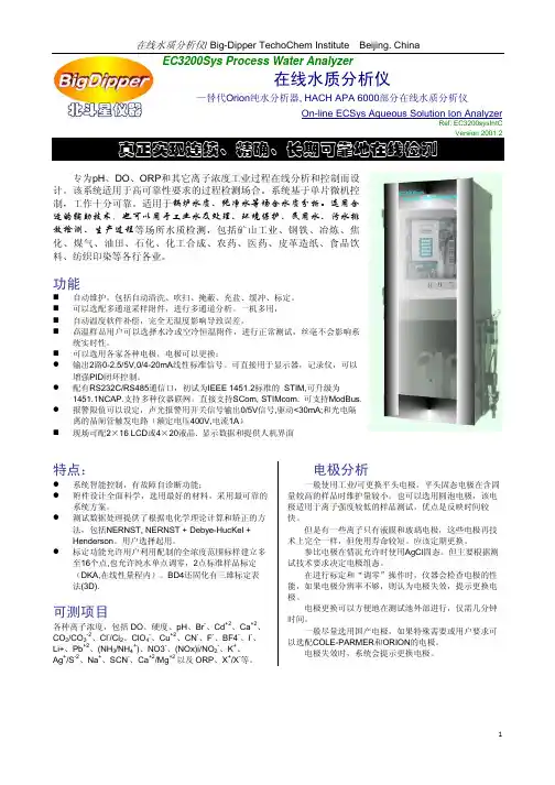
EC3200Sys Process Water Analyzer在线水质分析仪—替代Orion纯水分析器, HACH APA 6000部分在线水质分析仪On-line ECSys Aqueous Solution Ion AnalyzerRef: EC3200sysIntCVersion 2001.2 专为pH、DO、ORP和其它离子浓度工业过程在线分析和控制而设计。
该系统适用于高可靠性要求的过程检测场合。
系统基于单片微机控制,工作十分可靠。
适用于锅炉水质、纯净水等场合水质分析。
选用合适的辅助技术,也可以用于工业水及处理、环境保护、民用水、污水排放检测、生产过程等场所水质检测,包括矿山工业、钢铁、冶炼、焦化、煤气、油田、石化、化工合成、农药、医药、皮革造纸、食品饮料、纺织印染等各行各业。
功能自动维护,包括自动清洗、吹扫、掩蔽、充盐、缓冲、标定。
可以选配多通道采样附件,进行多通道分析。
一机多用,自动温度软件补偿,完全无温度影响导致误差。
高温样品用户可以选择水冷或空冷恒温附件,进行正常测试,丝毫不会影响系统实时性。
可以选用各家各种电极,电极可以更换;z输出2路0-2.5/5V,0/4-20mA线性标准信号。
可直接用于显示器,记录仪,可以增强PID闭环控制。
z配有RS232C/RS485通信口,初试为IEEE 1451.2标准的 STIM,可升级为1451.1NCAP.支持多种仪器联网。
直接支持SCom, STIMcom. 可支持ModBus.z报警限值可以设定,声光报警用开关信号输出0/5V信号,驱动<30mA;和光电隔离的晶闸管触发电路(额定电压400V,电流1A)现场可配2×16 LCD或4×20液晶. 显示数据和提供人机界面特点:z系统智能控制,有故障自诊断功能;z附件设计全面科学,选用最好的材料,采用最可靠的系统方案。
z测试数据处理提供了根据电化学理论计算和矫正的方法,包括NERNST, NERNST + Debye-HucKel +Henderson。
水质测试仪功能、使用方法宝子们,今天咱们来唠唠水质测试仪这个超有趣的小玩意儿。
先说说它的功能吧。
水质测试仪就像一个水质小侦探呢。
它能检测水里各种各样的东西。
比如说,它能知道水里的酸碱度,也就是pH值。
这个可重要啦,如果水太酸或者太碱,对咱们的身体可不好,就像喝了奇怪味道的饮料,可能会让你肚子不舒服哦。
而且对于那些养小金鱼或者种水生植物的小伙伴,合适的pH值能让小金鱼游得更欢快,植物长得更茁壮。
它还能检测水里的余氯含量呢。
余氯这东西,在自来水里经常有,适量的余氯能杀菌消毒,可要是太多了,那水就会有股怪味儿,就像游泳池里水味儿太重的那种感觉。
有了水质测试仪,就能清楚知道余氯有没有超标啦。
还有哦,水质测试仪能检测水的硬度。
水要是太硬,烧水的时候就容易结水垢,就像给水壶穿上了一层白白的铠甲。
硬水用来洗衣服的话,肥皂也不太容易起泡泡,感觉洗不干净呢。
再来说说这水质测试仪咋用的吧。
不同的水质测试仪可能会有点小差别,但总体来说都不难。
一般拿到测试仪,先得把它给校准一下,就像给它定个小规矩,让它知道什么是标准的。
这一步可不能偷懒哦,不然测出来的结果就不准啦。
校准完了之后呢,就可以把要检测的水取一点样本啦。
如果是检测家里的自来水,直接用个小杯子接一点就行。
要是检测鱼缸里的水,可得小心点,别把小金鱼也舀出来了哈。
然后把测试仪的探头放到水里,就像把小触角伸进水里探索秘密一样。
过一会儿,测试仪上就会显示出各种检测结果啦,是不是超级简单呢。
宝子们,有了水质测试仪,就像给咱们的用水安全上了一道保险。
不管是喝的水,还是家里其他用水,都能心里有数啦。
而且啊,用这个小玩意儿还挺好玩的呢,可以时不时检测一下,就当是和水做个小游戏,看看它是不是健康又干净。
所以呀,要是你还没有这个小助手,不妨考虑一下哦,它会给你带来不少小惊喜的呢。

WATER ANALYSIS INSTRUMENTS UV-Vis spectrophotometerChlorophyll is the green pigment in plants that allows them to create energy fromlight to photosynthesize. By measuring chlorophyll, you are indirectly measuring the amount of photosynthesizing plants (such as algae or phytoplankton) found in a sample. Chlorophyll a pigment is universal to all plant types, while other chlorophylls (such as b, c1, c2, d, f ) may be specific to certain plants, algae, or cyanobacteria and may be used to identify major algal groups present.1Why measure chlorophyll a ?The flow of nutrients, such as phosphorous and nitrogen, into inland and coastal waters contributes to enhanced algae growth. Figure 1, on the next page, shows how chlorophyll a can correlate to dissolved inorganic nitrogen (DIN).2 Changes to nutrient loadings can also change the phytoplankton species composition and diversity.High levels of algae often indicate poor water quality and low levels often suggest good conditions. Elevated phytoplankton levels can lead to reduced water clarity, affecting sea grass growth and related fisheries. In extreme cases, eutrophication can lead to hypoxia (oxygen-depleted “dead zones” that kill fish, shellfish, and crustaceans) and harmful and/or toxic algal blooms. From a water quality perspective, chlorophyll a is the best available, most direct measure of the amount and quality of phytoplankton and the potential to lead to reduced water clarity and low dissolved oxygen impairments.3 Chlorophyll a is often reported in mass per unit volume, e.g. µg/L, mg/L. The chlorophyll a threshold for impacts on fish is generally considered to be 100 µg/L.2 The cleanest waters will have chlorophyll a levels of less than 5 µg/L.5 The specific, applicable water quality standard will depend on the uses and goals for that water body.S mart NotesWhat is chlorophyll a?Who measures chlorophyll a?Drinking water treatment plants with surface water impoundments will measure chlorophyll a to manage the source water. This may include predicting and controlling algae blooms or determining where to draw water to avoid algae intake, which can clog filtration systems, increase organic load, cause a public health nuisance, and necessitate extra treatment. In the United States, other agencies analyzing chlorophyll a include: US Army Corps of Engineers; US Environmental Protection Agency (US EPA); state environmental agencies and laboratories; Chesapeake Bay Program; US Geological Survey (USGS); National Oceanic and Atmospheric Administration (NOAA); Audubon of Florida; academic institutions, and others.How is chlorophyll a measured?Chlorophyll a is measured by filtering a known amount of sample water through a filter, usually a glass fiber filter. The filter is ground up in an acetone solution, which is then processed and analyzed. There are three standard techniques for determining chlorophyll a concentrations: spectrophotometry, fluorometry, and high-performance liquid chromatography (HPLC). Spectrophotometry is the most commonly used laboratory method. The sample processing time is typically 1–5 minutes, the estimated detection limit (DL) is 0.08 mg/L6 (using a 1 cm cell;use larger for lower DL), and the instrumentation cost is low. The HPLC method is able to differentiate between chlorophyll types and accessory pigments, but is a slower and more demanding technique, e.g., 20–25 minutes of sample processing time. The cost of an HPLC instrument may be 10 times the cost of a spectrophotometer, and there are considerable ongoing consumables costs. Fluorescence is an indirect method for measuring chlorophyll a, and is well suited for remote monitoring.To measure chlorophyll a by the spectrophotometric technique, a spectrophotometer with a narrow band width (pass) is used to take measurements at multiple wavelengths. For example, the trichromatic method uses measurements at 750 nm (turbidity correction), 664 nm (chlorophyll a), 647 nm (chlorophyll b correction), and 630 nm (chlorophyll c1, c2 correction). See absorption spectra for chlorophyll a and b in the image to the right,, Figure 2.An alternate method uses measurements at 750, 664, and/ or 665 nm before and after acidification, which corrects for pheophytin a and turbidity interferences. The wavelengths and equations used will depend on the method chosen. Examples of accepted chlorophyll a testing methods include US EPA 446.0, Standard Methods 10200 H, ASTM D3731, DIN 38412-16, ISO 10260, and others. Equipment for testing chlorophyll a by spectrophotometerThe Thermo Scientific™ Orion™ AquaMate™ UV-Vis Spectrophotometer is a good choice for this testingand meets the requirements for accepted chlorophyll a testing methods, such as listed above. The instrumenthas the necessary narrow band pass, covers the required wavelengths, accommodates sample cells from 1 to 10 cm, and is designed to offer the accuracy, dependability andease of use your lab requires.Figure 1. Chlorophyll a corresponds to DIN.Figure 2. Absorption spectra for chloropylla and b.References1. Method 10200 H. Chlorophyll, Standard Methods for the Examination of Water andWastewater, .2. Chlorophyll a concentrations, Ozcoasts, Marine & Coastal Environment Group,Geoscience Australia, .au/indicators/chlorophyll_a.jsp.3. Ambient Water Quality Criteria, USEPA April 2003, /content/publications/cbp_13142.pdf.4. Nielson, J. and P. Jernakoff, P. 1996. A review of the interaction of sediment and waterquality with benthic communities. Port Phillip Bay Environmental Study. TechnicalReport No. 25, 1-130.5. Method 446.0 In Vitro Determination of Chlorophylls a, b, c1 + c2 and Pheopigmentsin Marine and Freshwater Algae by Visible Spectrophotometry. National ExposureResearch Laboratory, US EPA, Cincinnati, OH. https:///si/si_public_file_download.cfm?p_download_id=525241&Lab=NERL.6. Absorption spectra for chlorophyll a and b, https:///biol13100/index.php/File:Chlorophyll.JPGF ind out more at /aquamateThis product is intended for General Laboratory Use. It is the customer’s responsibility to ensure that the performance of the product is suitable for customer’s specific use or application. © 2016, 2020 Thermo Fisher Scientific Inc. All rights reserved. All trademarks are the property of Thermo Fisher Scientific and its subsidiaries unless otherwise specified. SN-CHLOROPHYLL-E 1020。
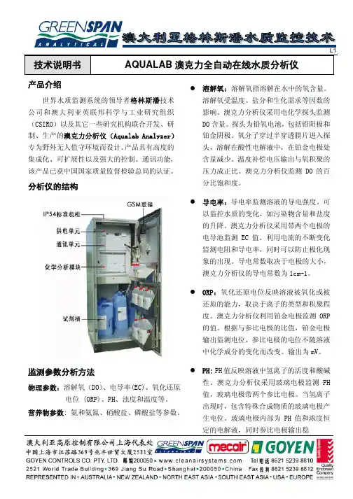
技术说明书 AQUALAB澳克力全自动在线水质分析仪产品介绍世界水质监测系统的领导者格林斯潘技术公司和澳大利亚英联邦科学与工业研究组织(CSIRO)以及其它一些研究机构联合开发、研制、生产的澳克力分析仪(Aqualab Analyzer)专为野外无人值守环境而设计。
产品具有高度的集成化、可扩展性以及强大的控制、通讯功能,该产品已获中国国家质量监督检验总局的认证。
分析仪的结构监测参数分析方法物理参数:溶解氧(DO)、电导率(EC)、氧化还原电位 (ORP)、PH、浊度和温度等。
营养物参数: 氨和氨氮、硝酸盐、磷酸盐等参数。
溶解氧:溶解氧指溶解在水中的氧含量。
溶解氧受温度、盐分和生化需求等因数的影响。
澳克力分析仪采用电化学探头监测DO含量。
探头为铅氧电池,包括铅阳极和铂金阴极。
氧分子穿过半穿透膜片进入探头,溶解在酸性电解液中,在铂金电极处含量减少。
温度补偿电压输出与氧积聚的压力成正比。
澳克力分析仪监测DO的百分比饱和度。
导电率:导电率监测溶液的导电强度。
可以监控水质的变化,如污染物含量和盐度的升降。
澳克力分析仪采用带两个电极的电导池监测EC值。
利用电流的不断变化监测电阻和导电率,同时可以防止极化现象的出现。
导电常数取决于电极的大小,澳克力分析仪的导电常数为1cm-1。
ORP:氧化还原电位反映溶液被氧化或被还原的能力,取决于离子的类型和积聚程度。
澳克力分析仪利用铂金电极监测ORP 的值。
根据与参比电极的比值,铂金电极输出监测电位,参比电极的电位不随溶液中化学成分的变化而改变。
输出为mV。
PH: PH值反映溶液中氢离子的活度和酸碱性。
澳克力分析仪采用玻璃电极监测PH 值,玻璃电极带两个参比电极。
当氢离子出现时,包含特殊合成物质的玻璃电极产生电位。
玻璃电极内部为PH值和浓度恒定的电解液,同时参比电极输出稳定的补偿电压。
在监测间隙,PH电极储存在潮湿的空气中,可以延长使用寿命。
浊度:浊度指溶液中悬浮物的含量。
Octadem奥克丹 便携式水质分析仪测试操作说明无锡奥克丹生物科技有限公司1. 奥克丹水质分析仪不同型号功能对比2. 基本操作2.1 比色皿加入水样和试剂严格按要求加入比色皿水样和试剂是精确检测的前提。
测试使用的比色皿必须干净透明,没有明显划痕或磨损。
比色皿加入水样后液面与比色皿最高刻度必须对齐(使用胶头吸管微调)。
加入试剂时必须按仪器指定编号(①,②或③)和规定用量(见试剂瓶标注)加入。
试剂有液体、粉末和试剂条三种类型。
液体试剂使用滴瓶滴入比色皿(或量管);粉末试剂使用专用量勺加入比色皿;试剂条则通过在比色皿水样中搅动加入试剂。
试剂条2.2 比色皿插入仪器∙ 比色皿三角形符号面对显示屏。
∙ 比色皿溶液中不能有气泡(持比色皿上部,用另手食指向下敲打比色皿上沿除去气泡)。
∙ 比色皿下面方形部分必须擦干净。
如果比色皿扣盖,用力压盖挤出盖边缘的水擦拭干净。
∙ 如果比色皿没扣比色皿盖,测试时需要使用仪器遮光盖。
2.3 “快速”和“常规” 测试(仅W 系列产品适用)(按 OK ) 或者“快速”(按 )测试方式。
“常规”测试方式是由仪器根据试剂显色反应所需要的时间控制检测进程。
为了获得最佳检测结果,建议用户在一般情况下都选择“常规”测试方式。
“快速”测试方式由用户自己控制检测进程。
除非对检测精度要求较低或对试剂显色所需时间有充分把握,用户不宜选择这一测试方式。
2.4 混浊水样当水中微生物及漂浮物较多或者水样在比色皿中呈现混浊时,测试前需要对水样进行过滤处理。
请选用中速定量滤纸过滤水样。
建议不要使用新滤纸过滤的前20毫升水。
过滤水样可以将滤纸按下图方式折叠放置在50mL量杯上,让水样通过滤纸进入量杯。
2.5超出测试范围水样当检测指标超过试剂测试范围,仪器会提示稀释水样5倍后再重新检测。
用户可以使用50mL量杯进行稀释:先将待测水样加到量杯的10mL刻度,然后加入纯净水至50mL刻度并摇晃混匀。
稀释后水样的检测值乘以5即为原水样的检测值。
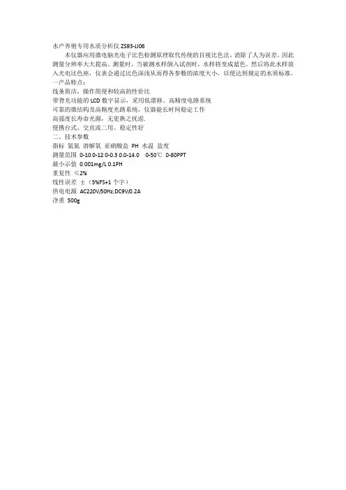
水产养殖专用水质分析仪ZS93-JJ06
本仪器应用微电脑光电子比色检测原理取代传统的目视比色法。
消除了人为误差,因此测量分辨率大大提高。
测量时,当被测水样倒入试剂时,水样将变成蓝色。
然后将此水样放入光电比色座,仪表会通过比色深浅从而得各参数的浓度大小,以便达到规定的水质标准。
一产品特点:
线条简洁,操作简便和较高的性价比
带背光功能的LCD数字显示,采用低漂移、高精度电路系统
可靠的微结构及高精度光路系统,仪器能长时间稳定工作
高强度长寿命光源,无更换之忧虑.
便携台式、交直流二用、稳定性好
二、技术参数
指标氨氮溶解氧亚硝酸盐PH 水温盐度
测量范围0-10 0-12 0-0.3 0.0-14.0 0-50℃0-80PPT
最小示值0.001mg/L 0.1PH
重复性≤2%
线性误差±(5%FS+1个字)
供电电源AC220V/50Hz;DC9V/0.2A
净重500g。
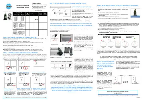
STEP 1 -DETERMINE THE SHAPE OF YOUR WATER TANKSelect your tank type that is closest in shape to your tank from the pictures and complete the chart above. Thecapacity on the tank should be noted.∙ When taking the tank dimensions, confirm it is prepared for step 4.∙ Determine the dimensions of your tank either from manufacturer’s data for the tank or by physicallymeasuring to complete the chart above.∙ You only need to note the dimensions indicated on the chart shown above.∙ For bunded tanks the information required is for the internal tank only, where the Tekelek Eco-WaterTransmitter will be located.∙ To determine the tank height measure from the top of the tank, i.e. where the Tekelek Eco-WaterTransmitter will be positioned, to the bottom of the tank (N.B. of the internal tank in a bunded tank)STEP 2 – SETTING UP YOUR TEKELEK Eco-Water MONITOROn first powering up your Tekelek Eco-Water Monitor, it automatically displays its setup mode. The TekelekEco-Water Monitor screen will show SETUP 1. One or more segments of the display may be flashing. Flashingsegments are circled in RED in the diagrams. Please follow the steps below to store the settings to configureyour Tekelek Eco-Water Monitor. If you make a mistake and store an incorrect value, simply press ENTERrepeatedly until you return to the same SETUP number, then select the correct value and press ENTER to store.SETUP 1 – Setting the time (hrs)Adjust the hour displayed using❒/♦. Press ENTER to save.SETUP 2 – Setting the time(mins) Adjust minutes dis-played using ❒/♦. PressENTER to save.Packaging contains:∙ Tekelek Eco-Water Monitor + mains plug∙ Tekelek Eco-Water Transmitter + 2 selftapping screws + weather seal∙ Tekelek Eco-Water Product manual∙ This installation guideSETUP 3 – Setting the tank typeSelect Tank Type i.e. A, B, or C, using❒/♦to match the Type you notedfrom above. Press ENTER to save.SETUP 4 – Setting the tankcapacity (Ltr/Gal) Refer to thechart above for nominal capac-ity and adjust the amount inLitres/Gallons displayed using❒/♦. Press ENTER to save.SETUP 5 – Setting the tank height (cm/inch) Refer to the chart above for tankheight and adjust the amount in cm/inch displayed using ❒/♦.Press ENTERto save. Note that if Tank Type ‘A’ wasselected, SETUP 6 will be skipped.SETUP 6 (Type B & C tanks only) -Setting the tank width (cm/inch)Refer to the tank chart above forthe width and adjust the amountin cm/inches displayed using ❒/♦. Press ENTER to save.N.B. If you cannot select the correct dimensions for your tank, confirm that you have selected the correct tank type.Eco-Water MonitorInstallation guideDo NOT install/ fit your Tekelek Eco-Water Transmitter to the tank until after step 3.Tank TypeHeight(H) cmsWidth(W) cmsBrimfulCapacity(Ltrs)NominalCapacity(Ltrs)(95% of Brimful)Your tankdimension chartN/AType B -(H >= W) Oval/cylindrical horizontalType A -Rectangular/cylindrical verticalType C -(W > H) Lo profileSTEP 2 – SETTING UP YOUR TEKELEK Eco-Water MONITOR —cont’dSETUP 7 – Setting the Low Water Audible AlarmAlarm on: The Tekelek Eco-Water Monitor will soundan audible beep when the water level falls to below5% of usable water remaining.Alarm off: Disengages the alarm.For further information please refer to Section 6 ofthe Product manual.Select AL ON/OFF using ❒/♦. When the displayshows your preferred setting press ENTER to save.SETUP should now be complete. Press SETUP to exit and progress to STEP 3.On exiting SETUP mode the Tekelek Eco-Water Monitor temporarily displays ‘CALC’.N.B. If at any stage you exit SETUP mode for any reason, simply hold SETUP for 3 seconds to begin again.STEP 3 - MATCHING THE TEKELEK Eco-Water TRANSMITTER TO THE Eco-Water MONI-The Tekelek Eco-Water Monitor must be in LEARN mode which can be entered in one of two ways:A) Pressing SETUP after completing STEP 2 aboveB) Disconnecting and reconnecting the powerWhen in LEARN mode the display shows ‘Lrn’ inthe main display area (see Image 1). LEARNmode will last for 2 minutes during which timeyou must ‘match/pair’ the Tekelek Eco-WaterTransmitter to the Tekelek Eco-Water Monitor.To match/pair the units: Note the location ofthe alignment pin on the right hand side of thebase of the Monitor (see Image 2).Using thescrew hole of the Transmitter,slot it onto thepin as shown in Image 3.The display of the Transmitter should be facingin the same direction as the Monitor’s displayas shown in Image 4.When located properly, the bars in the bargraph display of both the Tekelek Eco-WaterMonitor and the Tekelek Eco-Water Trans-mitter will flash and begin to increase in synchtogether rising from one bar to ten bars. Acontinuous audible beep and flashing LED onthe monitor will also indicate the matching is inprogress. Continue to hold the units in placeuntil all 10 bars are flashing. The Tekelek Eco-Water Monitor will make a loud beep and theRed LED on the Tekelek Eco-Water Transmitterwill flash. They are now matched and shouldbe separated immediately.Following the ‘matching/pairing’ the Tekelek Eco-Water Transmitter will send data continuously to theTekelek Eco-Water Monitor for approximately 10 minutes. Each time the Monitor receives a reading, it willmake a clicking noise and the LED on the Monitor will blink (this is ‘fast’ mode for the transmitter).During this time, confirm that the matching procedure was successful by slowly raising and lowering theTekelek Eco-Water Transmitter over a flat surface and observing that the display in the Tekelek Eco-WaterMonitor changes. ‘Fast’ mode will stop after 10 minutes. The Tekelek Eco-Water Transmitter is now ready tofit onto the tank and should be fitted whilst in ‘Fast’ mode.You should now proceed immediately to STEP 4 and fit the Tekelek Eco-WaterTransmitter to your tank. If it is not fitted within 10 minutes, the Tekelek Eco -WaterMonitor may display an error or an incorrect reading. It may then take up to 2 hoursbefore the correct tank level information is displayed on the Tekelek Eco-WaterMonitor screen.Image 3: Correct positioning Image 4: AlignmentImage 2: Alignment PinImage 1: ‘Lrn’ modeSTEP 4 - INSTALLING THE TEKELEK ECO-WATER TRANSMITTER ON THE TANKThe procedure is the same for fitting to both old and new tanks. For bunded tanksensure that the Tekelek Eco-Water Transmitter is located on top of the innertank.For Tanks with pre-drilled 30/32mm (1.22 inch) hole∙ Remove cap from hole and insert transmitter, ensuring the weather seal issecurely in place.∙ Ensure the transmitter is vertical on top of the tank.∙ Tighten on to the tank using the 2 stainless steel 19mm (0.75 inch) long self-For Tanks without pre-drilled holes∙ If the tank is not pre-drilled, then using a 30/32mm (1.22 inch) hole saw, drill the hole in the top of thetank in a suitable area to allow ease of fitting the transmitter such that the transmitter can see the tankcontents. Position it so that there are no internal obstructions that may interfere with the ultrasonicsignal (i.e. Ribs, Stays, Side of Tank, internal equipment).∙ Use the Installation Help diagram below to ensure suitable fitting.∙ Ensure the transmitter is vertical on top of the tank.∙ Tighten on to the tank using the 2 stainless steel 19mm (0.75 inch) long self-tapping screws supplied.Do not use longer screws. Do not over-tighten.Check the Tekelek Eco-Water Monitor display 2 hours after mounting the transmitter & verify that yourTekelek Eco-Water Monitor display shows the tank level in the bar-graph area & the volume information inthe main display area. If not, please consult the ‘Troubleshooting’ section of the Tekelek Eco-Water ProductManual.N.B. the bar-graph displays on the Tekelek Eco-Water Transmitter and the Tekelek Eco-WaterMonitor may not be the same. The transmitter display indicates the top 1m of the tank whilethe Tekelek Eco-Water Monitor bar-graph displays the liquid level relative to the overall tankSTEP 5 - (OPTIONAL) PERFORMONLY IF THERE WAS A DELAY ININSTALLING THE TEKELEKEco-Water TRANSMITTER ONTHE TANKYou only need to complete this step if there was a gap of morethan an hour between completing STEP 3 and STEP 4.STEP 5 is otherwise completed automatically as part of STEP 3.When your Tekelek Eco-Water Transmitter is installed and hasbeen confirmed as working, reset the usage calculations bypressing SETUP for 3 seconds to enter SETUP mode and thenpress ENTER repeatedly until SETUP 9 is shown.The segments at the bottom of thedisplay will be flashing. Press theENTER key for 5 seconds. The screenwill temporarily show ‘CALC’ and thenreturns to showing SETUP1 - Settingthe Time (hrs). Press SETUP to leaveSETUP mode.Setup of your Tekelek Eco-WaterMonitor is now complete and it willnow begin to monitor and track yourwater consumption on a day to dayand week to week basis. On the ‘Daysto Empty’ CURRENT informationscreen, ‘---’ will be displayed for thefirst week in use.Should you have any queries please contact,****************The contents and images in this guide are subject to copyright and may not be reproduced without the permission of Tekelek Europe Ltd.9-####-##。
水质分析仪器使用方法说明书一、引言水质是生活中重要的组成部分,对于保障人们的健康和环境保护起着关键作用。
水质分析仪器是一种用于评估水质的工具,准确的使用方法对于保证结果的可靠性至关重要。
本说明书将详细介绍水质分析仪器的正确使用方法,帮助用户正确操作仪器,获得准确可靠的分析结果。
二、设备概述1. 仪器名称:水质分析仪器2. 主要功能:用于测试水质中各种参数,如PH值、溶解氧、浑浊度等。
3. 仪器结构:包括主机、传感器、数据显示屏等部分。
三、使用前的准备1. 检查仪器:确保仪器外观完好,无损坏和松动现象。
2. 供电和保养:接通仪器电源并保证供电稳定。
定期清洁仪器外壳,确保传感器表面清洁。
3. 校准操作:根据需要选择校准参数和校准液进行校准操作,确保仪器的准确性。
四、仪器使用步骤1. 打开仪器:按下电源按钮,仪器将自动启动,系统初始化完成后即可开始使用。
2. 参数选择:根据所需测试项目,在仪器界面上选择相应的测试参数。
3. 传感器配置:将相应传感器连接到仪器的接口上,并确保连接牢固。
4. 校准操作:按照仪器界面提示,选择校准功能并按照校准液的要求进行操作。
5. 取样操作:使用取样器将待测试的水样取出,并将水样倒入仪器中的样品槽。
6. 测试操作:按下测试按钮,仪器将自动进行测试,并在显示屏上显示结果。
7. 结果记录:记录测试结果和相关参数,并及时关闭仪器以节省能源。
五、注意事项1. 仪器应放置在平稳、干燥、通风的环境中,避免撞击和湿气侵入。
2. 仪器和传感器使用前后应进行清洁,确保准确的测试结果。
3. 在校准前后,仪器和传感器应保持在稳定的环境温度下,避免温度的影响。
4. 使用时应注意操作规范,避免操作过程中产生误操作,影响仪器的使用寿命。
5. 不得随意更换仪器内部部件,如需更换应由专业人员进行操作。
6. 使用完成后,应及时关闭仪器电源,以免浪费能源和损坏仪器。
六、故障排除1. 仪器无法启动:检查电源是否通电,确认连接是否松动。
水产养殖专用水质分析仪水产养殖是一种重要的农业产业,水质是水产养殖的关键因素之一、水质的好坏直接影响着水产养殖的效益和质量。
因此,水产养殖专用水质分析仪的应用非常重要。
首先,水产养殖专用水质分析仪可以测量水体中的溶解氧含量。
溶解氧是水生生物生存所必需的气体,它直接关系到水中生物体的呼吸和代谢。
通过测量溶解氧,可以了解水体中氧气的供应情况,从而控制水质中溶解氧的含量,保持水体中的氧气充足,提供良好的生存环境。
其次,水产养殖专用水质分析仪可以测量水体的温度。
水温是水生生物生长发育的重要因素,适宜的水温可以促进水生生物的代谢和食欲,提高水产养殖的产出。
通过实时监测水温,可以及时调整水体的温度,提供适宜的生长环境,避免温度过高或过低对水产养殖的影响。
此外,水产养殖专用水质分析仪还可以测量水体的pH值。
pH值是水体酸碱度的指示,对于水生生物的生存和生长都有重要影响。
不同种类的水生生物对pH值的适宜范围是有所不同的,通过测量pH值,可以了解水体的酸碱度状况,及时调整水体的pH值,创造适宜的生存环境,促进水生生物的生长和繁殖。
此外,水产养殖专用水质分析仪还可以测量水体的浊度。
浊度是水体中悬浮物和溶解物质引起的光线散射的程度,直接反映了水体中的杂质含量。
不同种类的水生生物对水质的浊度要求不同,通过测量浊度,可以控制水体中的悬浮物和溶解物质的含量,保持水质清澈透明,提高水生生物的生长环境。
最后,水产养殖专用水质分析仪还可以测量水体中的盐度。
盐度是海水和咸水水体的重要指标之一,不同种类的水生生物对盐度有特定的适应范围。
通过测量盐度,可以确定水体中的盐度含量,调整水体的盐度,为养殖场提供适宜的水生生物种类和品种。
总之,水产养殖专用水质分析仪是提高水产养殖效益和质量的重要工具。
它可以为水产养殖提供准确的、实时的水质数据,帮助养殖户了解养殖水体的质量,及时调整水体的各项指标,创造适宜的生存环境,提高水产养殖的产出和经济效益。
水质分析的重要性(奥克丹)溶解氧的高低,对于水质的影响也是很大的。
在高溶解氧的水体中,有机质在好氧菌的作用下分解完全,其产物为二氧化碳、无机盐、硝酸盐等无毒无害物质。
而在缺氧或低氧的时候,有机质主要靠厌氧菌分解,其产物为氨氮、亚硝酸盐、硫化氢、有机胺类、有机酸等。
对养殖品种有很大的毒害作用。
在高密度养殖的情况下,前期养殖品种小,对水体的压力小,水质一般正常,溶解氧比较高;或者白天在藻类光合作用下,溶解氧很高。
此时多开增氧机常常是浪费电,增加不必要的成本。
而养殖后期,或者水质比较差的时候,也许全开增氧机也不能保持水体中有充足的溶解氧。
其时,可能需要采取额外的措施。
所以,经常的,乃至24小时监测溶解氧是预防水体缺氧必要的措施。
综上所叙,溶解氧测量,最好能够每天多次,不光测量表层的溶解氧,而且能够测量底层的溶解氧,而且最好能够在塘口就地测量。
pH值。
pH值同溶解氧一样,也有明显的垂直、水平、时间的变化,而且和溶解氧是一致的。
pH值的变化,主要是由于浮游植物的光合作用消耗二氧化碳使pH升高,生物的呼吸作用放出二氧化碳,降低pH值,有机质的分解也会产生二氧化碳和有机酸从而降低pH值。
水产养殖品种对pH值的有一个最佳适应范围。
一般是7.5-8.5之间。
水体自身有一定的缓冲能力,能保持水体pH值不会升的太高,也不会下降的太低。
但是,当pH的升高和降低超过了水的缓冲能力或者水体本身的缓冲能力比较差的时候,过高或过低的pH值就会影响到水产养殖动物的生长乃至生存。
我们检测水体pH值,就是为了能够保持水体pH 值在一个适合的范围以内,并且通过了解pH值了解水质的变化。
比如,如果pH早晚的差别太大,可能水体的缓冲能力比较差,或者藻类繁殖过剩。
pH早晚差别太小,可能是水体藻类老化,光合作用能力下降。
pH太低,可能是水体有机质过低,水体酸化或者是酸性土。
pH太高,可能土质是碱性土或者长期施用无机化肥,藻类繁殖过剩,消耗大量的二氧化碳,造成pH升高。
INSTRUCTION MANUALMULTI-PARAMETER TESTR 35 SERIESpH / Conductivity / TDS / Salinity / TemperaturePart of Thermo Fisher Scientific 68X441601 Rev. 1 March 2010Thank you for selecting our Multi-Parameter Testr. This manual serves the following (3) models:• PCTestr 35 (Eutech PCTEST35-01X441504 / Oakton 35425-00)pH / Conductivity / Temperature• PTTestr 35 (Eutech PCTEST35-01X441505 / Oakton 35425-05)pH / Total Dissolved Solids / Temperature• PCSTestr 35 (Eutech PCSTEST35-01X441506 / Oakton 35425-10)pH / Conductivity / Total Dissolved Solids / Salinity / TemperatureGetting Started:Your instrument has been factory calibrated and usually works well out of the box. However, afterextended periods of non-use, it’s best to remove the sensor cap and soak thesensor (pictured here) in warm tap water or pH buffer for 10 minutes or so. Abrief rinse with deionized (DI) water is OK, but avoid soaking or storing indeionized water as this will shorten the pH electrode life. Prior to takingmeasurements, periodic calibration with certified standards is recommended forbest accuracy.Your Testr begins in the measuring mode that was previously used. Just prior to measurement orwhen switching modes, you will see the setting associated with each parameter i.e.) pH (buffergroup selected), Conductivity (Auto), TDS (factor), Salinity (unit of measure).Setup:Your Testr allows customization of various settings. To access the setup mode:1.With the Testr off, keep thepressed down while you press and release .(Setup) will appear, then as you release , (Parameter) will appear.2.Press orto choose(Parameter Setup) or (System Setup)menu.3.Press to enter the selected setup menu.*IMPORTANT*It is necessary to save your Parameter and Systemchanges in order for them to take effect.1.When you are finished making your desired changes, press bothand at the sametime and keep them pressed until you see “SA” (Save) on the display.2.With the primary display “SA” and secondary display “YES”, press to save thechanges. The instrument will resume measurement mode with new setting(s).Note: If auto-shut off is used, changes will be automatically saved 8.5 minutes after the lastchange was made.Parameter Setup: Select to make changes relating to theparameters – pH, Conductivity TDS, Salinity. Note: only the PCS Testr will have all ofthese options. See below for menus available from each parameter. To Navigate themenus:∙Press to select or confirm the displayed option.∙Press or to scroll thru options or change values.pH Options:∙USA or NIST Buffer Group for calibration buffer option.5-pt calibration (all points) or 3-pt calibration (middle three points only).Salinity (SALt) Option (PCS Testr only)∙Choose PPt (parts per thousand) or Per (percentage %) as unit of measure.Total Dissolved Solids (tDS) Option (PT and PCS Tester only)∙FACt factor the instrument uses to convert from conductivity to TDS value.Adjustable from 0.40 to 1.00 (default factor is 0.71).Conductivity Options (PC and PCS Tester only)∙ A.Cal (Automatic Calibration) Choose YES or NO (manual).TIP:The PC Testr 35 and PCS Testr 35 are capable of automatic or manualconductivity calibration. In automatic calibration mode, the meter will automaticallychoose one of (3) conductivity calibration standards depending on the ranges listedbelow. If you will only use 84 µS, 1413 µS, or 12.88 mS calibration standards,automatic calibration is a time saving option. If you intend to calibrate with one or morestandards that are not listed below, choose “NO” which will disable auto calibration andallow you to enter your desired value manually.Conductivity Range Automatic Calibration Value Available with0.0 – 200.0 µS 84µS PCSonly201 – 2000 µS 1413µS PC or PCS2.01 – 20.00 mS 12.88 mS PC or PCS∙SPC (Single-Point Calibration) Choose YES or NO (multi-point calibration).TIP:The PC Testr 35 and PCS Testr 35 are capable of single or multi-point conductivitycalibration. Use Single-Point Calibration to apply a single calibration value across allranges. Use Multi-Point Calibration for individual calibration in each range. This willrestrict an individual calibration so that it is applied to one range only. When usingmulti-point calibration, perform a calibration in each range that you expect to use forbest results.System Setup:Select to make changes relating to the system. See below for available menus.Note: other than changing Temperature units, it is advised to keep the factory defaultsettings for best results. To Navigate the System menus:∙Press to select or confirm the displayed option.∙Press or to scroll thru menu options or change values.∙Unit rSt (Instrument reset)PH (pH) or EC (electrical conductivity / TDS / Salinity)CAL (calibration reset) or FCt (Reset to factory default settings)∙Set A.Off (Automatic shut off after 8.5 minutes) Choose YES or NO.∙Set t.C (Temperature Coefficient) 0.0-10.0% (2.1% is default)∙Set AtC (Auto Temperature Compensation) Choose YES or NO (25°C is used).∙Set °C °F (select temperature units) Choose °C elsius or °F ahrenheit.Temperature Calibration:The factory temperature calibration should last for the life of the original sensor since itdoesn’t normally drift. Temperature calibration is always recommended upon sensorreplacement. It may also be desirable to adjust the temperature to match a certifiedaccurate thermometer or another Testr. The temperature value is common to allparameters so only one calibration is needed. To perform temperature calibration:1.Press to turn on meter. Place the reference thermometer and your Testrinto the same sample. Allow enough time for both to stabilize.2.Press as needed to select the pH measuring mode. Press to begin pHcalibration mode.3.Press for 5 seconds to begin temperature calibration mode. The currenttemperature will be displayed on top while the factory default temperature isbelow.4.Press or to manually adjust to the desired temperature—up to ± 5°C or ± 9° F of the factory default value.5.Press to confirm and return to the pH measuring mode.pH Calibration:For best results, calibrate with certified accurate pH calibration standards (buffers).You may calibrate up to five points with the USA (1.68, 4.01, 7.00, 10.01, 12.45) orthe NIST (1.68, 4.01, 6.86, 9.18, 12.45) buffer group.1.Press to turn meter on and to select pH mode as needed.2.Rinse the sensor with clean water. Immerse the sensor into your pH buffer andpress . The primary display will show the un-calibrated pH value, while thesecondary display should search for and lock on the closest automatic calibrationvalue.3.Allow the primary display to stabilize, then press to confirm the calibrationvalue. The primary value will blink briefly before the secondary value automaticallyscrolls thru the remaining pH buffers available for calibration.4. Repeat steps 2 & 3 with additional buffers or press to return tomeasurement mode.Conductivity Calibration (Automatic):For best results, calibrate with certified accurate conductivity calibration standards. Selection of multi-point calibration will allow up to three of the following values, while Single-point calibration will allow only one; choose 84 μS, 1413 μS, or 12.88 mS.Conductivity Range Automatic Calibration Value Available with 0.0 – 200.0 µS 84 µS PCS only 201 – 2000 µS 1413 µS PC or PCS 2.01 – 20.00 mS 12.88 mS PC or PCS1. Pressto turn meter on and to select conductivity mode as needed. 2.Rinse the sensor with clean water. Immerse the sensor into your standard andpress. The primary display will show the un-calibrated value, while the secondary display display should search for and lock on the closest automatic calibration value. 3. Allow the primary display to stabilize, then pressto confirm the calibration value. The primary value will blink briefly before returning to measurement mode. 4.Repeat steps 2 & 3 with additional calibrations standards if desired.Conductivity, TDS, & Salinity Calibration (Manual):For best results, calibrate with certified accurate calibration standards. 1 point per range.Conductivity (3-pt) TDS (3-pt) Salinity (1-pt) 0.0 – 200.0 µS* 0.0 – 99.9 ppm* 201 – 2000 µS 100 – 999 ppm 2.01 – 20.00 mS 1.00 – 10 ppt1.00 – 10 ppt*Range only available with PCS Testr 351. Press to turn meter on and to select conductivity, TDS, or salinitymode.2.Rinse the sensor with clean water. Immerse the sensor into your standard andpress. The primary display will show the un-calibrated value, while the secondary display will display the factory default calibration. 3. Press or to manually adjust the primary display to your calibrationstandard.4. Press to confirm the new adjusted value. The primary value will blink brieflybefore returning to measurement mode.5. Repeat steps 2 & 3 with additional calibration standards if desired.Hold Function:For prolonged observation of a reading, press during measurement mode to freeze the display. The “HOLD” indicator will display when the reading is held. Torelease the held value and resume live measurement, press .Sensor Replacement:Your instrument includes a replaceable sensor (Eutech PCSENSOR - 01X097108 / Oakton 35425-50). If the tip gets damaged or as the sensor wears over time, theentire sensor can easily be replaced. To remove the old sensor, simply twist off the ribbed collar and pull the sensor straight out.To install the new sensor, line up the tabs and 8 pins of the sensor to the instrument body. Twist ribbed collar back on to keep waterproof rating and secure sensor. The O-rings should create a watertight seal and provide some resistance when twisting.Battery Replacement:Your Testr includes (4) 1.5V alkaline batteries. LR44 or A76 battery types are suitable and commonly available. Replace all (4) batteries together. Waiting too long to replace the batteries can lead to inaccurate readings and is the most common cause of problems. Twist andunscrew to remove the battery cover at the top of the Testr. Pull on the white ribbon to remove the batteries. Note the correct polarity of the instrument before installing. The flat side of the battery is +. Place new batteries on top of the white ribbon so they can be easily removed next time. Hand tighten the battery cover to keep waterproof rating.Storage:The sensor does not require special storage. Rinse with clean water after use andcover the sensor with the included cap. Keep at room temperature away from extreme temperatures. The sensor can easily be re-hydrated by soaking if stored dry.MessageIndicates>75% battery life remaining 50-75% battery life remaining25-50% battery life remaining No bars & blinking = replace batteriesErr Calibration error, usually attempting to calibrate to a value which is out of range or under range.Unstable pH reading / Slow responseBroken or dirty sensor. Clean, rehydrate, and replace if necessary. Could also be due to low battery condition or sample with temperature that has not stabilized.“Ur” (Under range)or “Or” (Over range) Measured value is out of range. Most often caused by dry electrode that needs to be re-hydrated / soaked. Sensor may not becompletely submersed or is not connected to Testr body properly. Meter not responsive If “Hold” on display, press Hold key to resume live measurement. Secondary display continually scrollsThe automatic calibration standard is not within expected calibration range. Use fresh standard or an alternate calibration standard.Warranty:The waterproof Testrs are warranted to be free from manufacturing defects for 1 year and the electrode module is warranted for 6 months, unless otherwise stated. If repair, adjustment or replacement is necessary and has not been the result of abuse or misuse within the time period specified, please return the tester – freight prepaid – and correction will be made without charge. Out of warranty products will be repaired on a charge basis.Return of Items:Authorization must be obtained from your distributor before returning items for any reason. When applying for authorization, please include information regarding thereason the item(s) are to be returned. Note: We reserve the right to make improvements in design, construction and appearance of products without notice.Prices are subject to change without notice.For more information on our products, please contact us or visit our websites: Oakton Instruments 625 E Bunker Court Vernon Hills, IL 60061, USATel: (1) 888-462-5866Fax: (1) 847-247-2984 **************** Eutech Instruments Pte Ltd Blk 55, Ayer Rajah Crescent, #04-16/24, Singapore 139949 Tel: (65) 6778 6876 Fax: (65) 6773 0836 *********************** 。
---------------------------------------------------------------最新资料推荐------------------------------------------------------在线水质分析仪说明书目录1.操作说明......................................................... ........................................................... ................. 3 2.G::SYSTEM 简介 ........................................................ ........................................................... .... 4 3 常用术语......................................................... ........................................................... ................... 5 4.测量......................................................... ........................................................... ......................... 64.1 光谱测量原理 ................................................ 6 4.2 功能检查/参考测量...........................................6 4.3 探头的安装.................................................. 75.安装......................................................... ........................................................... ............................ 85.1 产品清1/ 50单 (8)5.2 组装........................................................8 5.3 连接压缩空气清洗装置 ........................................ 8 5.4 探头的安装 .................................................. 96 操作......................................................... ........................................................... ......................... 106.1 con::lyte 的启动 ........................................... 10 6.2 探头的搜索和初始化.. (117)测量显示/主要菜单......................................................... ........................................................... 127.1 各按键的功能............................................... 12 7.2 读数和信息显示 .............................................12 7.3 主菜单/菜单项.............................................. 138 测量/CON::LYTE 操作 ........................................................ ......................................................---------------------------------------------------------------最新资料推荐------------------------------------------------------ 158.1 自动.......................................................15 8.2 手动操作................................................... 15 8.3 运行日志和数据.............................................16 8.4 settings(测量参数设置)................................... 16 8.4.1 Settings \ s::canpoint............................... 16 8.4.2 Settings \ Measurement............................... 17 8.4.3 Settings \ Cleaning. (17)8.4.4 In-/Output(电源和中继界面)...........................18 8.4.5 In-/Outputs \ mA Output..............................18 8.4.6 In-/Outputs \ Relays (Fault Relay)...................18 8.4.7 In-/Outputs \ Reset settings.........................19 8.5 Calibration................................................19 8.5.1 Calibration \ Global calibration.....................19 8.5.2 Calibration \ Local cal.<Par1>....................... 20 8.5.3 Calibration \ function control....................... 21 8.6 Information................................................3/ 5021 8.7 Extra (211)---------------------------------------------------------------最新资料推荐------------------------------------------------------9 附件......................................................... ........................................................... ......................... 229.1 多功能玻片................................................. 22 9.2 安装棒.....................................................23 9.3 旁路器具 (2410)运行日志消息......................................................... ........................................................... ....... 26 11 软件的下载说明(CON::LYTE) ............................................. ............................................. 29 12 联系地址......................................................... ........................................................... (292)5/ 501.操作说明通过购买 s::can G::system 在线水质分析仪,您会获得一种易于操作,应用范围广的高科技测量产品。