issc芯片
- 格式:docx
- 大小:36.83 KB
- 文档页数:2
国内外18家蓝⽛芯⽚⼚商及产品型号集合技术的出现,让⼈们的电脑、⼿机和各种便携设备,在没有线路的情况下也可以实现连结,这让原先被各种连接线塞满的屋⼦、桌⾯,变得⼲净整洁,如很多朋友都在使⽤的⽆线⿏标、⽿机等等。
⽆线通信技术可以分为近距离⽆线通信和远距离⽆线通信。
近距离⽆线通信包括蓝⽛、WIFI、1.Qualcomm(收购CSR)蓝⽛芯⽚业务,来源于2014年收购的CSR公司,CSR全称CambridgeSiliconRo,是⼀家Fabless⽆⼯⼚半导体制造商,主要产品线为单芯⽚的蓝⽛芯⽚、GPS芯⽚。
⾼通官⽹显⽰,其蓝⽛产品主要分为两⼤类,⽤于语⾳、⾳乐产品的蓝⽛和⽤于物联⽹的低功耗蓝⽛。
上述图表中提到的蓝⽛单模,是只兼容经典蓝⽛(包含蓝⽛3.0/2.1/2.0/1.2/1.1/1.0等)或低功耗蓝⽛(包含蓝⽛5.0/4.2/4.1/4.0等)其中的⼀种。
蓝⽛双模则是既可以兼容经典蓝⽛⼜兼容低功耗蓝⽛;也可理解为蓝⽛单模是⾳频或数传,⽽双模是⾳频(经典蓝⽛)+数传(低功耗蓝⽛)。
2.xas Instruments成⽴于1930年,是⼀家全球知名的数字信号处理与模拟技术半导体供应商,除半导体业务外,3.Cypress成⽴于1982年,是⼀家全球知名电⼦芯⽚制造商,中⽂名为,公司主要⽣产⾼性能IC产品,⽤于数据传输、远程通讯、PC和军⽤系统。
4.Nordic成⽴于1983年,总部位于挪威特隆赫姆。
公司主要提供可以从⼩型电源(如⼿表电池)长时间运⾏的超低功耗(ULP)⽆线芯⽚。
5.DialogDialog是⼀家⽆晶圆⼚半导体公司,主要致⼒于开发⽤于消费电⼦产品的⾼度集成的混合信号产品。
6.ST成⽴于1988年,由意⼤利的SGS微电⼦公司和法国Thomson半导体公司合并⽽成,是全球领先的半导体解决⽅案提供商,可为智能驾驶和物联⽹提供关键解决⽅案。
7.8.NXP成⽴于2006年,先前由飞利浦于50多年前所创⽴。
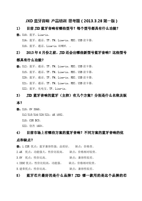
JXD蓝牙音响产品培训思考题(2013.3.28第一版)1)目前JXD蓝牙音响有哪些型号?每个型号都具有什么功能?答:X10:蓝牙、Line-in。
X16:蓝牙、通话、TF、FM、Line-in、REC、USB读卡器。
X18:蓝牙、通话、Line-in 双喇叭。
2)2013年6月份之前,JXD还会出哪些新型号蓝牙音响?这些型号都具有什么功能?答:X12:蓝牙、通话、TF、FM、Line-in、REC、USB读卡器。
X15:蓝牙、通话、TF、FM、Line-in、REC、USB读卡器。
X20:蓝牙、通话、TF、FM、Line-in、REC、USB读卡器。
X21:蓝牙、通话、TF、FM、Line-in、REC、USB读卡器。
X22:蓝牙、充电宝、TF、Line-in。
3)JXD蓝牙音响的蓝牙(主控)有几个方案?分别是什么名称及版本?答:X10:OV 3860。
X12/X15/X16/X20/X21:AK 1052。
X18:CSR BC5。
X22:创杰 1684。
4)目前市场上有哪些方案的蓝牙音响?不同方案的蓝牙音响的优点和缺点?答:1.CSR 优点:蓝牙兼容性强,品质好。
缺点:价格贵。
2.AK 优点:功能强大,性价比较高。
缺点:价格相对较贵。
3.OV 优点:性价比高。
缺点:兼容性较差。
4.ISSC优点:性价比较高,功能强。
缺点:价格相对较贵。
5.建荣优点:性价比高。
缺点:兼容性较差。
5)蓝牙芯片最好的是什么品牌?JXD哪一款用的是这个品牌的芯片?答:CSR。
X18。
6)JXD蓝牙音响与市场上的蓝牙音响相比,有哪些优势?答:1.功能强大,蓝牙、通话、TF、FM、Line-in、REC、USB读卡器功能都齐全。
2.性价比高,功能多,工艺好,价格便宜。
3.售后有保障,JXD18年品牌,售后无忧。
7)JXD蓝牙音响中用安凯方案的有那几个型号?答:X12/X15/X16/X20/X218)未来3-4个月内,我司还有哪些蓝牙音响会陆续上市?答:X12/X15/X20/X21/X229)JXD蓝牙音响产品的材质工艺有哪些?每个型号分别为什么材质工艺?答:X10:塑胶+喷油+UV。
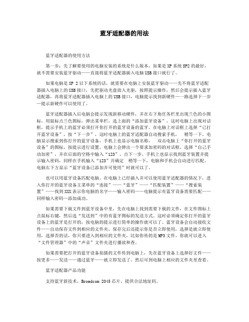
蓝牙适配器的用法蓝牙适配器的使用方法第一步:先了解要使用的电脑安装的系统是什么版本,如果是XP系统SP2的最好,就不需要安装蓝牙驱动——直接将蓝牙适配器插入电脑USB接口就行了。
如果电脑是XP 2以下系统的话,就需要在电脑上安装蓝牙驱动——先不将蓝牙适配器插入电脑上的USB接口,先把驱动光盘放入光驱,按照提示操作,然后会提示插入蓝牙适配器,再将蓝牙适配器插入电脑上的USB接口,电脑提示找到新硬件—一路选择下一步—提示新硬件可以使用了。
蓝牙适配器插入后电脑会提示发现新移动硬件,并在右下角任务栏里出现兰色的小图标,用鼠标点兰色图标,弹出菜单栏,选上面的“添加蓝牙设备”。
这时电脑上出现对话框,提示手机上的蓝牙必须打开你打开的蓝牙设备的蓝牙。
在电脑上对话框上选择“已打开蓝牙设备”,按“下一步”,这时电脑上的蓝牙适配器自动搜索手机,稍等一下,电脑显示搜索到你打开的蓝牙设备,手机上也显示电脑名称,双击电脑上“你打开的蓝牙设备”的图标,按提示进行设置。
电脑上会弹出一个要求加密码的对话框,选择“自己手动加密”,并在后面的空格中输入“123”,点下一步。
手机上也显示找到蓝牙装置并提示输入密码,同样在手机输入“123”并确定稍等一下,电脑和手机会自动进行匹配。
电脑右下方显示“蓝牙设备已添加并可使用”时就可以了。
也可以用蓝牙设备匹配电脑。
在电脑上已经插入并可以使用蓝牙适配器的情况下,进入你打开的蓝牙设备主菜单的“连接”——“蓝牙”——“匹配装置”——“搜索装置”——找到XXX表示你电脑的名字——输入密码——电脑提示有蓝牙设备需要匹配——同样输入密码—添加成功。
如果需要下载文件到蓝牙设备中里,先在电脑上找到需要下载的文件,在文件图标上点鼠标右键,然后选“发送到”中的有蓝牙图标的发送方式。
这时必须确定你打开的蓝牙设备上的蓝牙是打开的,按电脑的提示进行简单的操作就可以了。
蓝牙设备会自动接收文件——自动保存文件到相应的文件夹,保存完后还提示你是否立即使用,选择是就立即使用,选择否的话,你只要进入到相应的文件夹,比如你传的是MP3文件,你就可以进入“文件管理器”中的“声音”文件夹进行播放和查。
蓝牙无法连接手机nokia 无法验证手机pc套件无法验证手机通过蓝牙用手机...蓝牙相关文章蓝牙(Bluetooth)的名字来源于10世纪丹麦国王Harald Blatand-英译为Harold Bluetooth。
蓝牙技术起源于1998年5月,由爱立信、IBM、Intel、诺基亚、东芝等5家公司联合制定的近距离无线通信技术规范。
蓝牙技术实际上是一种短距离无线电技术,利用"蓝牙"技术,能够有效地简化掌上电脑、笔记本电脑和移动电话手机等移动通信终端设备之间的通信,也能够成功地简化以上这些设备与因特网Internet之间的通信,从而使这些现代通信设备与因特网之间的数据传输变得更加迅速高效,为无线通信拓宽道路。
现在无线局域网产品已经陆续支持蓝牙技术。
(图为蓝牙标志)蓝牙产品采用的是一种称之为跳频的技术,能够抗信号衰落;工作于2.4GHz的ISM (即工业、科学、医学)频段,以省去申请专用许可证的麻烦;采用FM调制方式,使设备变得更为简单可靠;"蓝牙"的每一个话音通道支持64kb/s的同步话音,最大数据传输值为1Mbps,异步通道支持的最大速率为721Kbps、反向应答速率为57.6Kbps的非对称连接,或者432.6kb/s的对称连接。
相对我们以前常见的红外传输,蓝牙传输的速度和稳定性、兼容性方面都大大胜出了,对于智能手机的玩家来说,备置一个蓝牙适配器还是很有必要的。
1.相对红外:全面胜出,只价格上稍贵2.相对数据线:安装甚至比数据线简单,目前的Windows XP sp2已经内置蓝牙驱动,无须再装任何驱动,真正即插即用,可以完成数据线能完成的绝大部分功能,携带方便,且可兼容其它蓝牙设备(如蓝牙键盘、鼠标、耳机等)价格相差不多3.相对读卡器:速度当然没法比,但是可以同步经管手机,使手机真正和电脑相连,在小文件的传输上实在方便,免去读卡器的机卡分离,甚至可以共享对方的网络功能。
实现两台电脑蓝牙局域网共享宽带实现两台电脑蓝牙局域网共享宽带(转载)新的问题总是不断出现的,现在手上有两台笔记本电脑,一台有无线网卡,另外一台没有,想要将它们同时使用我的ADSL怎么办呢,没有无线网卡,没有有线或者无线路由,怎么办呢?我想到了用蓝牙技术来实现,但是之前我并没有尝试过,似乎之前也有朋友想我咨询过类似问题,但是当时由于条件有限,不能实际测试,终于在周末,花了几个小时的研究,成功通过蓝牙连接实现了宽带的共享,作此文备忘。
要想解决一个问题,最好的老师其实是搜索引擎,百度谷歌都是良师益友,通过对网络上仅有的一些类似文章的查阅,我发现都没有一篇写得很详细的,而是仅仅针对自己的条件作了一些说明,对可能遇到的疑惑未作深入解析,看完之后我也不明究理。
其实共享应该有四个要点: (这里我把已经接入有线宽带的机器称为主机,将另外一台机器称为从机。
)1.保证两台机器在同一工作组这点是比较容易被忽视的,因为很多机器默认的工作组是一样的,不设置也无妨,所以很多人在写下自己的共享过程时都忘记说明此过程的重要性了。
主机和从机最好都要设置一遍,在网络邻居里,依次:设置家庭或小型办公网络--下一步--下一步--(忽略已断开的网络硬件)--下一步--此计算机通过居民区的网关或网络上的其他计算机连接到Internet--下一步--(计算机描述和计算机名任意输入)下一步--(工作组名选择默认即可,但是一定要两台一样!)下一步--启用或者关闭文件共享均可--下一步--向导正在配置。
需要几分钟时间--完成该向导。
我不需要在其他计算机上运行该向导--下一步--完成2.连接蓝牙局域网蓝牙的驱动一般常见的有微软自带、IVT、Widcomm三类,我从来不建议使用微软自带的驱动,因为它的功能太弱,这里推荐使用IVT驱动的2.3.0版本,网上有很多破解版本,而Widcomm驱动也是可以的,但是该驱动在音频方面没有IVT驱动优秀,所以我首推IVT驱动。
如何通过蓝牙用手机控制电脑蓝牙无法连接手机nokia 无法验证手机pc套件无法验证手机通过蓝牙用手机...蓝牙相关文章蓝牙(Bluetooth)的名字来源于10世纪丹麦国王Harald Blatand-英译为Harold Bluetooth。
蓝牙技术起源于1998年5月,由爱立信、IBM、Intel、诺基亚、东芝等5家公司联合制定的近距离无线通信技术标准。
蓝牙技术实际上是一种短距离无线电技术,利用"蓝牙"技术,能够有效地简化掌上电脑、笔记本电脑和移动手机等移动通信终端设备之间的通信,也能够成功地简化以上这些设备与因特网Internet之间的通信,从而使这些现代通信设备与因特网之间的数据传输变得更加迅速高效,为无线通信拓宽道路。
现在无线局域网产品差不多连续支持蓝牙技术。
〔图为蓝牙标志〕蓝牙产品采纳的是一种称之为跳频的技术,能够抗信号衰落;工作于2.4GHz的ISM (即工业、科学、医学)频段,以省去申请专用许可证的苦恼;采纳FM调制方式,使设备变得更为简单可靠;"蓝牙"的每一个话音通道支持64kb/s的同步话音,最大数据传输值为1Mbps,异步通道支持的最大速率为721Kbps、反向应答速率为57.6Kbps的非对称连接,或者432.6kb/s的对称连接。
相对我们往常常见的红外传输,蓝牙传输的速度和稳固性、兼容性方面都大大胜出了,关于智能手机的玩家来说,备置一个蓝牙适配器依旧专门有必要的。
1.相对红外:全面胜出,只价格上稍贵2.相对数据线:安装甚至比数据线简单,目前的Windows XP sp2差不多内置蓝牙驱动,无须再装任何驱动,真正即插即用,能够完成数据线能完成的绝大部分功能,携带方便,且可兼容其它蓝牙设备〔如蓝牙键盘、鼠标、耳机等〕价格相差不多3.相对读卡器:速度因此没法比,然而能够同步治理手机,使手机真正和电脑相连,在小文件的传输上实在方便,免去读卡器的机卡分离,甚至能够共享对方的网络功能。
Bluetooth 4.1 Multimedia SOCGENERAL DESCRIPTION IS2020S is a compact, highly integrated, CMOS single-chip RF and baseband IC for preliminary Bluetooth v4.1 with Enhanced Data Rate 2.4GHz applications. This chip is fully compliant with Bluetooth specification and completely backward-compatible with Bluetooth 3.0, 2.0 or 1.2 systems. It incorporates Bluetooth 1M/2M/3Mbps RF, single-cycle MCU, MODEM, UART inte rface, and ISSC’s own Bluetooth software stack to achieve the required BT v4.1 with EDR functions.To provide the superior audio and voice quality, it also integrates a DSP co-processor, a PLL, and a CODEC dedicated for voice and audio applications.For voice, not only the basic CVSD encoding and decoding but also the enhanced noise reduction and echo cancellation are implemented by the built-in DSP to reach the better quality in the both sending and receiving sides. For enhanced audio applications, SBC and AAC (optional) decoding functions can be also carried out by DSP to satisfy Bluetooth A2DP requirements. In addition, to minimize the external components required for portable devices, a voltage sensor for battery, battery charger, a switching regulator and LDO are integrated to reduce BOM cost for various Bluetooth applications.FEATURES∙ Support preliminary Bluetooth v4.1function and backward compatible with BT3.0, 2.0 and 1.2.∙ ISSC’s own Bluetooth software stack forthe headset or speaker application. It supports following profiles : - Hands Free 1.6 - Headset 1.1 - A2DP 1.2 - AVRCP 1.5 - SPP 1.0∙ Integrated 16/32 bits DSP core running upto 72MHz that supports:- Dual microphone noise suppression - Echo cancelation- SBC/AAC_LC audio format decoding - Automatic volume control for speaker output∙ Integrated a 20-bit 98dB SNR( A-weighted) stereo DAC ∙ Connections to two phones withHFP/A2DP profiles∙ Built-in four languages ( Chinese/English/ Spanish/ French) voice prompts ∙ Ultra low power consumption under10mA for SCO/A2DP link∙ Capable charging voltage from an emptybattery and sustain a direct DC input voltage up to 7V∙ Charging current up to 350mA ∙ 7 mm x 7 mm 56 QFN packageAPPLICATIONS∙ Bluetooth stereo headset ∙ Bluetooth stereo speaker∙ Bluetooth stereo speaker phone ∙ Bluetooth car audio unitI SS C C ONF ID E N T IA LBluetooth 4.1 Multimedia SOCTable of Contents1 KEY FEATURES (3)2 PIN ASSIGNMENTS (6)3 TRANSCEIVER (10)4 MICROPROCESSOR (11)5 AUDIO .................................................................................................................................................. 126 POWER MANAGE UNIT ..................................................................................................................... 137 GENERAL PURPOSE IOS .................................................................................................................. 158 SPECIFICATIONS ............................................................................................................................... 16 9PACKAGE (28)I SS C C ONF ID E N T IAL1 Key FeaturesSystem Specification∙ Compliant with Bluetooth Specification v.4.1 (EDR) in 2.4 GHz ISM band Baseband Hardware ∙ 16MHz main clock input∙ Built-in internal ROM for program memory∙ Support to connect to two hosts ( phones, tablets…) with HFP or A2DP profiles simultaneously∙ Adaptive Frequency Hopping (AFH) avoids occupied RF channels ∙ Fast Connection supported RF Hardware∙ Fully Bluetooth 4.1 (EDR) system in 2.4 GHz ISM band.∙ Combined TX/RX RF terminal simplifies external matching and reduces externalantenna switches.∙ Max. +4dBm output power with 20 dB level control from register control. ∙ Built-in T/R switch for Class 2/3 application∙ To avoid temperature variation, temperature sensor with temperature calibration is utilized into bias current and gain control.∙ Fully integrated synthesizer has been created. There requires no external VCO, varactor diode, resonator and loop filter.∙ Crystal oscillation with built-in digital trimming for temperature/process variations. Audio processor∙ Support 64 kb/s A-Law or μ-Law PCM format, or CVSD (Continuous Variable Slope Delta Modulation) for SCO channel operation.I SS C C ONF ID E N T IA L∙ Noise suppression for dual analog microphone inputs ∙ Echo cancelation∙ SBC and optional AAC decoding ∙ Packet loss concealment∙ Build-in four languages (Chinese/ English/ Spanish/ French) voice prompts and 20 events for each one Audio Codec ∙ 20 bit codec∙ 98dB SNR DAC playback ∙ Dual microphone input∙ Integrate headphone amplifier for 16/32Ω speakersPeripherals∙ Built-in Lithium-ion battery charger∙ Integrate 3V, 1.8V LDO and Switching mode regulator ∙ Built-in ADC for battery monitor and voltage sense. ∙ Two LED driversFlexible HCI interface∙ High speed HCI-UART (Universal Asynchronous Receiver Transmitter) interfacePackage∙ 7x7mm 2 56QFN packageI SS C C ONF ID E N T IA LFunctional DiagramIFNOCCSSI2 PIN ASSIGNMENTSI SS C C ONF ID E N T IA L3 TRANSCEIVERIS2020S is design optimized for use in Bluetooth 2.4 GHz system. It contains a complete radio frequency transmitter/receiver section. An internal synthesizer generates a stable clock for synchronize with another device.TRANSMITTERThe internal PA has a maximum output power of +4dBm with level control 20dB from amplitude control. This is applied into Class2/3 radios without external RF PA.The transmitter features IQ direct conversion to minimize the frequency drift. And it can excess 30dB power range with temperature compensation machine.RECEVIERThe LNA operates with TR-combined mode for single port application.The ADC is utilized to sample input analogue wave to convert into digital for de-modulator analysis. Before the ADC, a channel filter has been integrated into receiver channel that can reduce the external component count and increase the anti-interference capability.The image rejection filter is to reject image frequency for low-IF architecture. This filter for low-IF architecture is implied to reduce external BPF component for super heterodyne architecture.There is an RSSI signal to the processor that it can control the power to make a good tradeoff for effective distance and current consumption.SYNTHESIZERA synthesizer generates a clock for radio transceiver operation. There is a VCO inside with tunable internal LC tank. It can reduce variation for components. A crystal oscillation with internal digital trimming circuit provides a stable clock for synthesizer. MODEMOn the Bluetooth v1.2 specification and below, 1 Mbps was the standard data rate based on Gaussian Frequency Shift Keying (GFSK) modulation scheme. This basic rate modem meets BDR requirements of Bluetooth v2.0 with EDR specification.On the Bluetooth v2.0 with EDR specification, Enhanced Data Rate (EDR) has been introduced to provide 2 and 3 Mbps data rates as well as 1 Mbps. This enhanced data rate modem meets EDR requirements of Bluetooth v2.0 with EDR specification. For the viewpoint of baseband, both BDR and EDR utilize the same 1MHz symbol rate and 1.6 KHz slot rate. For BDR, 1 symbol represents 1 bit. However each symbol in the payload part of EDR packets represents 2 or 3 bits. This is achieved by using two different modulations, π/4 DQ PSK and 8DPSK.I SS C C ONF ID E N T IA L4 MICROPROCESSORA single-cycle 8-bit MCU is inside IS2020S to carry out the required Bluetooth protocols. It can run at the range from 16MHz to a higher clock so that MCU firmware can dynamically consider the tradeoff between computing power and power consumption. MCU firmware is implemented in ROM (Read-Only-Memory) to minimize the power consumption of program execution and to save the cost of external flash.MEMORYA single-port synchronous interface is provided to memory. There are enough ROM and RAM to fulfill the requirement of processor. In addition, attached to the embedded processor bus are a register bank, a dedicated single-port memory, and flash memory. The processor coordinates all link control procedures and data movement using a set of pointer registers.EXTERNAL RESETA watchdog timer capable of reset the chip. It has an integrated Power-On Reset (POR) circuit that resets all circuits to a known power-on state. This action can also be driven by an external reset signal that can be used to externally control the device, forcing it into a power-on reset state. The RST signal input is active low and no connection is required in most applications.REFERENCE CLOCKIS2020S is composed of an integrated crystal oscillation function. It used a 16 MHz external crystal and two specified load capacitors that a high quality system reference timer source is obtained. This feature is typically used to remove the initial tolerance frequency errors associated with the crystal and its equivalent load capacitance in mass production. Frequency trim is achieved by adjusting the crystal load capacitance through on-chip trim capacitors C trim integrated in chip. The value of trimming capacitance is around 200fF per LSB at 5 bits word, therefore the overall adjustable clock frequency is around 40 KHz.trim C =200fF * (1~31)I SS C C ONF ID E N T IA L5 AUDIOThere are several stages for input and output that all can be programmed for varying gain response characteristics. At the microphone input side, you may use single-end input or differential input. One critical point in maintaining a high quality signal is to provide a stable bias voltage source for the condenser microphone’s FET. DC blocking capacitors may be used at both positive and negative sides of input. Internally, this analog signal is converted to 16-bit 8 kHz linear PCM data. The voice data taken from common memory is converted to an analogue value by a DAC. A multistage amplifier drives the audio signal and provides a differential signal between Line_out+ and Line_out-. The output amplifier is capable of driving a speaker directly if its impedance is 16/32Ω.DIGITAL SIGNAL PROCESSORA digital signal processor (DSP) cooperates with MCU to deal with audio section. It provides audio processing with some advanced features. The DSP includes the capability to cancel the acoustic echo that may be present in a headset or speaker. All processing is performed by a DSP with low power consumption. This technique will most effectively cancel the incoming echo signal without impact to the desired voice signal. An outgoing signal to the speaker which level exceeds a certain threshold (and therefore deemed likely to create echo) will result in suppression of signal along the input path from the microphone. Filtering is also applied and provides for a smoother transition for a more natural user experience.DUAL MICROPHONE NOISE REDUCTIONThis noise reduction technology virtually eliminates distracting background noise, including crowds, wind, vehicles and other interruptions to your conversations. It support dual microphone inputs that one for main vocal input and the other for background noise. Of course, it can use only main vocal input for single microphone application.CODECThis built-in codec contains a high Signal/Noise performance. This built-in codec contains a analog to digital converter (ADC), a digital to analog converter (DAC) and additional analog circuitry.Signal to noise ratio (SNR) is the supreme facts of a CODEC. It provides a very low noise level for background white noise. The main music stream and vocal become clear with this low noise level.I SS C C ONF ID E N T IA L6 POWER MANAGE UNITThe PMU inside the chip has two main features, charging a Li-ion battery and some regulators for voltage translation. A power switch is used to switch over the power source between battery and adaptor automatically. It also provides two LED drivers.CHARGING A BATTERYIS2020S includes a built-in battery charger optimized for use with lithium polymer batteries. The charger features a current sensor for charging control, user programmable current regulation and high accuracy voltage regulation.The charging current is configured in the EEPROM. Whenever the adaptor is plug-in, charging circuit is active. Reviving, Pre-charging, Constant Current and Constant V oltage modes are implemented and re-charging function is also included. The maximum charging current is 350mA.VOLTAGE MONITINGA 10-bit Successive-Approximation-Register analog to digital converter (SAR ADC) provides one dedicated channel for battery voltage level detection. The warning level is programmable and stored in the EEPROM. This ADC provides a good resolution that MCU can control the charging process.VOLTAGE REGULATIONThe built-in voltage converter is used to convert the battery or adaptor power for power supply. It also integrates hardware architecture to control power on/off procedure. The built-in programmable LDOs provide power for codec and digital IO pads. It is used to buffer the highI SN T IA Linput voltage from battery or adapter. This LDO need s 1uF bypass capacitor. SWITCHING REGULATORThere is a bulk voltage convert generating the voltage for RF and baseband core power. This converter has good conversion efficiency to save power and fast transient response.LED DRIVERThere are two dedicate LED drivers to control the LEDs. They provide enough sink current that LED can be connected directly with IS2020S.I SS C C ON F I D E N T IA L7 GENERAL PURPOSE IOsIS2020S provides six general purpose IOs for keys setting and saved in the EEPROM. The first button must be power key. The power on/off functions only can be set on MFB pin. There are four different operations for every button. They are short click, long click, double click and combinations.Some signals were generated to indicate or control outside devices. The most popular applications are NFC for easy pairing, external audio amplifier for louder speaker and buzzer for indication.I SNF IL8 SPECIFICATIONSESSICS SICS SINote:(1) C is set in EEPROM(2) Headroom = V ADAP_IN – V BAT(3) ENX2 is not allowed to be enabled when V ADAP_IN – V BAT > 2VC ONote: (1) f in=1KHz, B/W=20~20KHz, A-weighted, THD+N < 0.01%, 0dBFS signal, SLoad=100KΩINote: (1) f in =1KHz, B/W=20~20KHz, A-weighted, THD+N < 1%, 150mVpp inputI SS CS S II SS C C ONF ID E N T II SS C C ONF ID E N T IA LI SS C C ONF ID E N T。
Preliminary DatasheetIS1684S Bluetooth 3.0(EDR) Multimedia SOC1. General DescriptionISSC IS1684S is a compact, high integration, ultra-low cost, CMOS single-chip RF + baseband IC for Bluetooth v3.0(EDR) (Enhanced Data Rate) 2.4GHz applications. This chip is fully compliant with Bluetooth specification and completely backward-compatible with Bluetooth 1.1, 1.2, 2.0 or 2.1 systems.It incorporates Bluetooth 1M/2M/3Mbps RF, single-cycle 8051, TX/RX modem, memory controller, task/hopping controller, UART interface, and ISSC Bluetooth software stack to achieve the required Bluetooth v3.0(EDR) functions.The IS1684S is designed to support high quality audio applications, an audio engine and a high performance stereo DAC are integrated for this purpose.The audio engine supports the SBC audio decoding and equlizer to offer the best audio quality.In addition, to minimize the external components required for portable devices, a voltage sensor for battery, Li-ion battery charger, a switching regulator and LDOs are integrated to reduce BOM cost for various Bluetooth applications.The device incorporates built-in self-test (BIST) and auto-calibration functions to simplify production test.2. FeaturesSystem Specification•Compliant with Bluetooth Specification v.3.0 (EDR) in 2.4 GHz ISM bandBaseband Hardware•16MHz main clock input•Built-in internal ROM for program memory•Built-in 32 KB RAM for data storage and baseband data transfer buffering•Enhanced Power Control•Bluetooth 2.1 featureso Encryption Pause and Resumeo Erroneous Data Reportingo Extended Inquiry Responseo Link Supervision Timeout Changed Evento Non-Flushable Packet Boundary Flago Secure Simple Pairingo Sniff Subtracting•Support both Pico-net and Scatter-net applications•Hard-wired logic for modulation, demodulation, access code correlation, whitening, forward error correction (FEC), header error check (HEC), shorten hamming code, CRC generation/checking, frame check sequence (FCS), encryption bit stream generation, and transmit pulse shaping•Adaptive Frequency Hopping (AFH) avoids occupied RF channels•Fast Connection supportedRF Hardware•Fully Bluetooth 3.0 (EDR) system in 2.4 GHz ISM band.•Combined TX/RX RF terminal simplifies external matching and reduces external antenna switches.•Max. +4dBm output power with 20 dB level control from register control.•Build-in T/R switch for Class 2/3 application•Build-in channel filter.•To avoid temperature variation, temperature sensor with temperature calibration is utilized into bias current and gain control.•Fully integrated synthesizer has been created. There requires no external VCO, varactor diode, resonator and loop filter.•Crystal oscillation with build-in digital trimming for temperature/process variations.Audio processor•SBC decoding•Packet error concealmentAudio Codec•16 bit stereo codec•94dB SNR DAC playback•Integrate headphone amplifier for 16Ω speakersPeripherals•Built-in Lithium-ion battery charger•Integrate 3V, 1.8V LDO and Switching mode regulator•Built-in 10-bit Aux-ADC for battery monitor and voltage sense.•LED driverFlexible HCI interface•High speed HCI-UART (Universal Asynchronous Receiver Transmitter) interfacePackage•7x7mm2 56 pins, 0.4mm pitch SAW QFN standard package3.Functional Diagram5 Pin DescriptionsPin No. I/O Pin Name Pin Descriptions23 P SAR_AVDD SAR 1.8V input24 P SYS_PWR System Power Output25 P BK_VDD Buck VDD Power Input26 P BK_LX Buck feedback input27 P BK_GND Buck Ground28 P BK_OUT Buck output29 P MFB Multi-Function Push Button key, push high30 AI LED1 LED Driver 131 AI LED2 LED Driver 232 I/O P2_4 GPIO, default pull-high inputKEY PIN for FT TestSystem Configuration, H: Boot Mode33 I/O P2_2 GPIO, default pull-low input.Keep alive for external LDO power enable application.34 I/O P0_2 GPIO, default pull-high inputPlay/Pause key as the default setting35 I/O P2_7 GPIO, default pull-high inputFWD key when class 2 RFFWD key(short press) when class 1 RF36 I/O P0_5 GPIO, default pull-high inputKEY PIN for FT TestREV key when class 2 RFREV key(short press) when class 1 RF37 O HCI_TXD KEY PIN for FT Test HCI TX data38 I HCI_RXD KEY PIN for FT Test HCI RX data39 I/O P1_6 GPIO P1_6, default pull-high input Volume down key when class 2 RF Audio AMP Enable when class 1 RF40 P VDD_IO I/O power supply input41 I XO_P 16MHz Crystal input positivePin No. I/O Pin Name Pin Descriptions42 I XO_N 16MHz Crystal input negative43 RP VCC_RF RF power input for both synthesizer and TX/RX block44 I RX_CLASS1 Class1 RF RX path45 I/O RTX Class2 RTX path; Class1/Class2 TX path46 I/O P0_1 GPIO, default pull-high inputVolume up key when class 2 RF.Class1 Control signal of external TR switch when class 1 RF47 I/O P0_3 GPIO, default pull-high inputKEY PIN for FT TestUART RX_IND when class 2 RFClass1 Control signal of external TR switch when class 1 RF48 I/O P3_0 GPIO, default pull-high input Line-in Detector (Low Active)49 I/O P2_0 GPIO, default pull-high inputKEY PIN for FT TestSystem Configuration, H: Application L: Baseband(IBDK Mode)50 I/O P0_0 GPIO, default pull-low input.KEY PIN for FT TestSlide Switch Detector/TX_IND when class 2 RF51 I/O P0_4 GPIO, default pull-high inputAudio AMP Enable when class 2 RF52 P VDD_IO I/O power supply input53 I/O P3_5 GPIO 3_5, default pull-high input. Buzzer Signal Output54 I EAN Embedded ROM/External Flash enable H: Embedded; L: External Flash55 P 1V8 Core 1.8V power input56 AO AOHPR R-channel single ended analog headphone output57 P GND Exposed pad as groundApplication Note for GPIO Setting:1) KEY PIN for FT TestHCI_RXD, HCI_TXD, RST_N, P2_0, P2_4, P1_3, P1_2, P0_3, P0_5, P0_02) For Class2 RF application: VOL+:P0_1, VOL-: P1_6, FWD:P2_7, REV:P0_5, AUDIOAMP ENABLE: P0_43) For Class1 RF application: VOL+:P2_7(Long Press), VOL-: P0_5(Long Press),FWD:P2_7(Short Press) , REV: P0_5(Short Press) , AUDIO AMP ENABLE: P1_64) Play/Pause: P0_25) P1_2:EEPROM Clock/Clock Signal for OLED(5028-202 not support)P1_3:EEPROM Data/Data Signal for OLED(5028-202 not support)6) SLIDE SWITCH DETECT: P0_07) Buzzer Signal Output: P3_58) CLASS 1 RF TX: P0_1, CLASS 1 RF RX: P0_39) External LDO power enable keep alive: P2_210) S ystem Configuration: P2_0, P2_411) P0_0/P0_3 are used as TX_IND/RX_IND of UART control in MCU application6 Functional Description6.1 Overall ArchitectureThe ISSC IS1684S integrates an enhanced EDR Bluetooth RF & BB core, HCI controller, audio engine and an ENHANCED 8051 processor with an internal mask ROM for program memory and SRAM for data memory. An innovative interconnection structure called the Common-Memory Architecture (CMA) is designed to provide a fast and flexible data movement scheme between the embedded processor, Bluetooth core, and peripheral hardware.For audio application and power management, IS1684S has build-in an audio processor, mono codec and power management unit to reduce the external components.6.2 Radio Frequency (RF)6.2.1 TransmitterThe internal PA has a maximum output power of +4dBm with level control 20dB from amplitude control. This is applied into Class 2/3 radios without external RF PA. For Class1 application, the build-in level control can be used with external PA for power control requirement.The transmitter features IQ direct conversion to minimize the frequency drift. And it can excess 30dB power range with temperature compensation machine.6.2.2 ReceiverThe LNA can be operated into two type modes. One type is TR-combined mode for single port application. The other type is TR-separated mode for external PA/LNA application.An ADC is used to sample input analogue wave for digital demodulation. Before the ADC, a channel filter has been integrated into receiver channel to increase the anti-interference capacity and also reduce the external component count.For avoiding temperature variation issues, a temperature sensor with temperature calibration is utilized into bias current and gain control of LNA, Mixers, and RF AMP.6.2.3 SynthesizerThe internal loop filter is used to reduce external RC components. This can reduce cost and variations for components. This internal LC tank for VCO is utilized to reduce variation for components. The cost is down at the same time.A fully integrated synthesizer has been created. There requires no external VCO, varactor diode, resonator and loop filter.6.3 MODEMThere are three different modulations for Bluetooth v3.0 (EDR). Table 6.3 summarizes these modulations and data rate.Figure 6.3 Modulation type for Bluetooth v3.0 (EDR)Data Rate Modulation Bits/SymbolBDR: 1 Mbps GFSK 1EDR: 2 Mbps π/4 DQPSK 2EDR: 3 Mbps 8DPSK 36.3.1 Basic Data Rate MODEM (BDR)On the Bluetooth v1.2 specification and below, 1 Mbps was the standard data rate based on Gaussian Frequency Shift Keying (GFSK) modulation scheme. This basic rate modem meets BDR requirements of Bluetooth v3.0(EDR) specification.Figure 6.3.1 Data format for BDRAccess Code Header Payload6.3.2 Enhanced Data Rate MODEM (EDR)On the Bluetooth v3.0(EDR) specification, Enhanced Data Rate (EDR) has been introduced to provide 2 and 3 Mbps data rates as well as 1 Mbps. This enhanced data rate modem meets EDR requirements of Bluetooth v3.0(EDR) specification. For the viewpoint of baseband, both BDR and EDR utilize the same 1MHz symbol rate and 1.6 KHz slot rate. For BDR, 1 symbol represents 1 bit. However each symbol in the payload part of EDR packets represents 2 or 3 bits. This is achieved by using two different modulations, π/4 DQPSK and 8DPSK.Figure 6.3.2.A Data format for EDRAccess Code Header Guard Sync Payload TrailerFor π/4 DQPSK modulation, each symbol carries 2 bits of information. For its constellation diagram, although there are 8 possible phase states, the encoding scheme guarantees the trajectory of the modulation between symbols is restricted to 4 states. For a given startingpoint, every phase change between symbols is restricted to +45°, +135°, -45°, and -135°.Figure 6.3.2.B Phase shift & bit pattern for 2 MHz data ratePhase Shift Bit Pattern+45° (+π/4) 00+135° (+3π/4) 01-135°(-3π/4) 11-45°(-π/4) 10For 8DPSK modulation, each symbol carries 3 bits of information. For its constellation diagram, it is similar toπ/4 DQPSK but the trajectory of the modulation between symbols has 8 possible phase states. For a given starting point, every phase change between symbols is restricted to 0°, +45°, +90°, +135°, +180°, -135°, -90°, and -45°.Figure 6.3.2.C Phase shift & bit pattern for 3 MHz data ratePhase Shift Bit Pattern0° (+0) 000+45° (+π/4) 001+90° (+π/2) 011+135° (+3π/4) 010+180° (+π) 110-135° (-3π/4) 111-90° (-π/2) 101-45° (-π/4) 1006.4 BasebandThe following modules implemented in hardware constitute the Bluetooth Baseband Core. The frequency hopping sequence generator produces the correct hop frequency control sequence based on the Bluetooth clock, Bluetooth device address, and the current operating mode.The access code generates the access code based on the Lower Address Part (LAP) of the Bluetooth device address. The access code is comprised of the preamble, sync word and trailer bits. The detection of the access code uses correlation to detect a valid access code.Bluetooth uses two types of FEC: 1/3 repetition code and (15, 10) shorten Hamming code respectively. The former basically repeats each transmitted bit three times while the latter has 15 bits of codeword which contains 5 parity bits. The code has capability of correction of all single-bit errors in each codeword.The purpose of HEC is to protect the header bits. Dedicated header error code generator calculates the HEC bits in the header of a transmitted packet. While on the receiver side, HEC detects corrupted headers.A 16-bit CRC is adopted to protect payload data transmitted using certain types of Bluetooth packets.Information confidentiality can be protected by encryption of the packet payload. Dedicated encryption/decryption hardware is designed into the baseband core.6.5 MCUThe embedded processor for IS1684S is a single-cycle 8051 CPU. The embedded processor will be referred to as simply the processor, 8051, or MCU throughout the remainder of this document. There are a few minor differences between a standard 8051 and this CPU. These include:1. Alteration of memory timings to match internal and external memoryconfigurations.2. Modification of idle mode to disable internal CPU clocking. Onlyexternally-clocked interrupt sources can allow the CPU to recover from idle mode.A single-port synchronous interface is provided to memory. From this single port, the bandwidth is divided among the 7 interfaces spread amongst 5 physical busses described below:•Embedded processor bus•Baseband TX bus•Baseband RX bus•HCI TX bus•HCI RX bus•Audio bus•DMA busIn addition, attached to the embedded processor bus are a register bank, a dedicated single-port memory (data segment 1), and flash memory (program segment). The processor coordinates all link control procedures and data movement using a set of pointer registers. For example, when an HCI packet (from the host via USB or UART) is received into the HCI buffer, the processor is interrupted. The processor can then read astatus register to determine the HCI packet type and determine whether to set up the Baseband pointer registers for this memory region for RF-retransmission, or to otherwise directly perform packet processing with the CPU.6.6 Bluetooth Clock and TimersA Bluetooth standard 28-bit counter running at 3.2 kHz implements the native clock defined by Bluetooth specification. This clock provides the transmission and receiving timing of a half time slot (312.5 µs). Another finer counter implemented in 16 bits is also provided as the phase of a half time slot. This phase information is very helpful when a Bluetooth slave wants to adapt to its master’s clock. The counter is pre-scalable for the purpose of power saving operations. The diagram below describes a standard Bluetooth native clock and master clock. The clock signal is also used as a slot boundary signal to trigger a baseband packet transmission or receipt.There are several timers provided by the system, two timers for TX/RX and the others for general purpose.The powerful pre-scheduling functions for the transceiver are realized different sets of programmable timers. Each set of timers is associated with the task of transmission or receiving. When the timer is configured by firmware, it will automatically execute the TX or RX task at a specific time. Sub-tasks and timing for a TX task remain to be defined.Figure 6.6 Bluetooth clock6.7 HCI Control Logic for USB/UARTHardwired control logic is presented in front of the UART devices for HCI protocol handling and packet buffering. This control logic is part of the HCI controller defined in Bluetooth specification 1.2. This logic is partially responsible for the HCI protocol handling to/from the host and it also maps the registers of the UART devices indirectly to the 8051 such that the system can receive or send a HCI packet to/from the respective host interface. Major functions of this logic include:•HCI packet formatter and de-formatter (identifying the packet type)•Frame boundary determination, segmentation and reassembly of HCI packets.•HCI packet transmission, receiving, and buffering (using common memory HCI buffer).•Independent receive / transmit channels•Universal device interface6.7.1 HCI UART InterfaceAn embedded HCI UART (Universal Asynchronous Receiver Transmitter) with programmable data rate up to 3Mbps is included in this design. The HCI UART supports the following functions:•Full-Duplex operation•Programmable BAUD rate (using 16-bit input clock divider to obtain Baud Rate x16 or x24 or x13 clock base)•7 or 8 Data bits• 1 or 2 Stop bits•Even / Odd / Mark / Space / None Parity configurations•Break Generation / Detection•Maskable individual interrupts to CPU and combined Error interrupt to HCI•Selectable Direct CPU interface or interface to HCI module6.8 General Purpose I/OThe IS1684S provides 15 general purpose I/O ports. These general I/Os can be defined as input or output port individually by setting specific register bit. While setting as an input port, a build-in 50KΩpull high or pull low resistor can be enabled for different application purpose.6.9 Audio ProcessorThe IS1684S builds in an enhanced audio engine to offer high quality of audio for audio application. The standard SBC A2DP audio function is implemented in the audio engine.6.10 Audio DACThe build in audio circuits contain a digital to analog converter (DAC) and a headphone driver. The DAC output is available for both line level and through the headphone amplifier to drive a low impedance headphone. The headphone output volume is adjustable by the combination of the digital/analog gain control.Figure 6.10 Audio DAC6.11 Auxiliary ADCThe 10-bit auxiliary analog to digital converter (SAR ADC) provides one dedicated channel for battery power detection and one other channel for external peripheral sensing. This ADC has 10 bits resolution that provides an accurate monitoring for battery voltage. The operating current is very low and almost consumes no power when disabled.6.12 Power Management (PMU)The power management unit of IS1684S includes several power control blocks, linear regulators, switch-mode regulator, Aux-ADC, LED driver and Lithium-ion/Polymer battery charger.6.12.1 3V1_LDOThe IS1684S has build-in the programmable output voltage LDOs (1.8~3.2V) for codec and digital IO power supply. The programmable LDO is used to regulate the high input voltage from battery or adapter. This LDO needs 1uF bypass capacitor.6.12.2 Buck regulatorThe built-in programmable output voltage buck (1.8~2.4V) converts battery voltage for RF and baseband core power supply. This converter has high conversion efficiency and fast transient response.6.12.3 Voltage DectectorThe 10-bit Successive-Approximation analog to digital converter (SAR ADC) monitors the battery power and adapter power for charging and power management control.6.12.4 Li-ion Battery ChargerIS1684S includes a built-in battery charger optimized for use with lithium polymer batteries. The charger features a current sensor for charging control, user programmable current regulation and high accuracy voltage regulation. It charges the battery in four phases:reviving mode : 2mA charging current to charge BAT to 2.5Vpre-charge mode : 0.1C charging current to charge BAT to 3.0Vconstant current mode : 0.xC (default 0.7C) charging current to charge BAT to 4.2V (programmable)constant voltage mode : charging is terminated while the charging current drops below 0.YC (default 0.13C)Charging current in the constant current mode can be configured to provide a wide range of charging current up to 180mA (1mA per step). Charger will re-start charging if the battery voltage falls below an internal threshold.System operation is allowed when the battery is charging.6.13 Miscellaneous (Watchdog Timer, and Clock Divider)System related functions such as watchdog timer, Endian control, and interrupt vectors are also provided. The purpose of the watchdog timer is to provide a reset to CPU in case when the CPU fails to service the watchdog timer in a pre-defined (programmable) period.7 Electrical CharacteristicsAbsolute Maximum RatingsRating Min Max Max Operation Temperature -20ºC +70ºC ºCCore supply voltage VDD_CORE, VCC_RF,AVDD_SAR,AVDD_PLL1.7V 1.98VVCodec supply voltage VDD_AUDIO 3.3 V I/O voltage VDD_IO 3.3 VSupply voltage BK_VDD 4.7 V 3V1_VIN 5 V BAT_IN 4.3 V ADAP_IN 6 V LED[1:0] 5 V Power switch 6 VRecommended Operate ConditionSymbol Parameter Min Typical Max Unit V DD18 Digital core supply voltageSAR ADC supply voltageCODEC supply voltage1.62 1.8 1.92 VV DDIO I/O supply voltageRF supply voltage2.5 2.73.3 VT OPERATION Operating temperature range -20 +25 +70 ºC T stg Storage temperature -40 +125 ºC V LDO LDO supply voltage 1.8 3.3 V V BAT_IN Input voltage for SAR ADC 0.9 3.3 VRadio Characteristics: Transmitter section for BDRVCC_RF = 2.7V Temperature = 25ºC Min Typ MaxBluetoothspecificationUnitMaximum RF transmit power 3 4.0 -6 to 4 dBmRF power variation over temperaturerange with compensation enabled±2 dB RF power control range 20 ≥16 dB RF power range control resolution 0.5 dB 20dB bandwidth for modulated carrier 900 ≤1000 KHzACPNote:F0=2441MHz F = F0±2MHz -28 ≤-20 dBm F = F0±3MHz -46 ≤-40 dBmF = F0±>3MHz -54 ≤-40 dBm∆f1avg maximum modulation 150165 140<∆f1avg<175KHz∆f2max maximum modulation 140 150 ≥115 KHz ∆f2avg/∆f1avg0.95 1 ≥0.80ICFT (abs) 0 5 10 75 KHzDrift rate (abs) 2 7 ≤20 KHz/50usDrift (single slot packet, abs) 12 ≤25 KHz 2nd harmonic content @ Tx= 4dBm -53 ≤-47 dBm 3rd harmonic content @ Tx= 4dBm -55 ≤-47 dBmReceiver section for BDRTemperature = 25ºC Frequency(GHz)Min Typ MaxBluetoothspecificationUnitSensitivity at 0.1% BER for all basic rate packet types 2.402 -91≤-70 dBm 2.441 -912.480 -91Maximum received signal at 0.1%BER-10 ≥-20 dBm C/I co-channel 5 ≤11 dBAdjacent channel selectivity C/INote: F0=2441MHz F =F0+1MHz-7≤0 dB F =F0-1MHz-7 ≤0 dB F =F0+2MHz-36 ≤-30 dB F =F0-2MHz-22 ≤-9 dB F =F0-3MHz-24 ≤-20 dB F =F0+5MHz-50 ≤-40 dB F = F image-22 ≤-9 dBMaximum level of intermodulationinterferers-38 ≥-39 dBTransmitter Section for EDRTemperature = 25ºC Min Typ MaxBluetooth specificationUnitRelative transmit power -1.6-4 to 1 dBπ/4 DQPSK max carrier frequency stability |ωo|freq. error5≤10 for allblocksKHz |ωi|initial freq.error10≤75 for allblocksKHz|ωo+ωi|block freq.error10≤75 for allblocksKHz8DPSK max carrier frequency stability |ωo|freq. error5≤10 for allblocksKHz |ωi|initial freq.error10≤75 for allblocksKHz|ωo+ωi|block freq.error10≤75 for allblocksKHzπ/4 DQPSK modulation accuracy @ Tx= 2dBm RMS DEVM 7 ≤20 % 99% DEVM Pass ≤30 % Peak DEVM 25 ≤35 %8DQPSK modulation accuracy @ Tx=2dBm RMS DEVM 7≤13 % 99% DEVM Pass≤20 % Peak DEVM 20 ≤25 %In-band spurious emissionsNote: F0=2441MHz F > F0+3MHz <-54≤-40 dBm F = F0-3MHz -46≤-40 dBm F = F0-2MHz -28 ≤-20 dBm F = F0-1MHz -30 ≤-26 dBm F = F0+1MHz -30≤-26 dBm F = F0+2MHz -28≤-20 dBm F = F0+3MHz -46≤-40 dBmEDR differential phase encoding 100 ≥99 %Receiver Section for EDR8DPSK -21 ≤0 dBF = F0-3MHz π/4DQPSK-27 ≤-20 dB 8DPSK -20 ≤-13 dBF = F0+5MHz π/4DQPSK-52 ≤-40 dB 8DPSK -45 ≤-33 dBF = F image π/4DQPSK-21 ≤-7 dB 8DPSK -21 ≤0 dBAudio DACTest Condition: T= 25o C, Vdd=2.8V, 1KHz sine wave input, Bandwidth= 20~20KHz Parameter Condition Min. Typ. Max. Unit Output Level Full scale 2.1 Vpp Resolution 16 bits Output Sampling Rate 8 48 KHzSNR f in=1KHzB/W=20~20KHzA-weightedTHD+N < 0.01%0dBFS signalLoad=100KΩ8KHz 94 dB 16KHz 94dB 32KHz 94dB 44.1KHz 94dB 48KHz 94dBMax Output Power R L=16Ohm 35 mW R L=32Ohm 17 mWTHD+N 16Ohm load 0.05 % 100KΩload 0.01 %Digital Gain -54 4.85 dB Digital Gain Resolution 6 dB Analog Gain -28 3 dB Analog Gain step 1 dB Output resistance R L 8 16 Ohm Output capacitance Cp 500 pFCrosstalk between channelsL vs. R, measured at-10dBFS@1KHz input-90 -80 dBAnalog supply voltage(AVDD)1.82.83.0 VBattery ChargerCharging Mode (BAT_IN rising to 4.2V) Min Typ Max Unit Operation Temperature -20 70 ℃Input Voltage (Vin)Note: It needs more time to get battery fullycharged when Vin=4.5V4.5 6 VBattery trickle charge current(BAT_IN < trickle charge voltage threshold)0.1C mA Trickle charge voltage threshold 3 VMaximum battery charge current Headroom > 0.7V 350 mA Headroom = 0.3V 150 mAMinimum battery charge current Headroom > 0.7V 1 mA Headroom = 0.3V 1 mABattery charge termination current,% of fast charge current10 %Battery recharge hysteresis (Note1) 100 mVBattery recharge current (Note2)Note: C Battery capacity0.25C mANote1:When charging complete and the adapter is still in, the battery voltage will slowly drop down.When the voltage drop is larger than 100mV from the full voltage, the re-charging cycle will start.Note2:If the battery voltage during plug in is larger than 4V, the charging current will be limited to0.25C to avoid the battery voltage overshoot.Switching RegulatorNormal Operation Min Typ Max Unit Operation Temperature -20 70 ℃Input Voltage (Vin) 3 3.7 4.5 V Output Voltage (Vout) 1.6 1.85 2.4 mA Output Ripple 20 mVrms Max. Average Load Current(I load) 120 mA Max. Output Current (peak) 200 mAConversion Efficiency (Bat.@3.7V) I load =50mA 88% I load≥ 10mA 80I load≥ 250uA 65Switching Frequency 800 KHz Start-up current Limit 0 50 210 mA Start-up Settling Time 1.2 2 ms Shutdown Current <1 uALDONormal Operation Min Typ Max Unit Input Voltage (Vin) 3.0 4.5 VOutput Voltage (V OUT)(1) V OUT_CODEC(2) V OUT_IO V OUT = 2.9V (2.4~3.4V) 2.9V V OUT = 1.8V (1.3~2.3V) 1.8Accuracy (V IN=3.7V, I LOAD=100mA, 27’C) ±5 % Output Voltage adjustable step 100 mV/Step Output adjustment range ±0.5 V Start-up inrush current 200 400 mA Start-up Settling Time 250 500 µs Output current(average) 100 mA Output Current(peak) 150 mA Drop-out voltag e (I load = maximum outputcurrent)300 mV Quiescent Current(excluding load, I load < 1mA)45 µA Load Regulation (I load = 0mA to 100mA), ∆Vout 80 mV Shutdown Current<1 µA Note: Two 100mA LDOs, one for IO and one for audio CODEC.ClockParameters MIN TYP MAX Unit Crystal Frequency 16 MHz Frequency Tolerence ±20 ppm Operating Temperature -20 70 O C Trimming Capacitance 6.4 pF Trimming Step Size 0.2 pFDigital GPIO (2.8V)Parameters MIN TYP MAX Unit Input Voltage 2.7 3 3.6 V V IH (Input High Voltage) 2.0 Vdd V V IL (Input Low Voltage) 0 0.8 V Input Reference ResistorR PU (Pull-Up Resistor) 50K Ohm R PD (Pull-Down Resistor) 50K Ohm Output VoltageV OH (Output High Voltage) 2.4 Vdd V V OL (Output Low Voltage) 0 0.4 V8 Package InformationAppendix A. Reflow Profile1.) Follow: IPC/JEDEC J-STD-020 C2.) Condition:Average ramp-up rate (217℃ to peak): 1~2℃/sec max.Preheat:150~200C、60~180 secondsTemperature maintained above 217℃ : 60~150 secondsTime within 5℃ of actual peak temperature: 20 ~ 40 sec.Peak temperature:250+0/-5℃ or 260+0/-5℃Ramp-down rate : 3℃/sec. max.Time 25℃ to peak temperature : 8 minutes max.Cycle interval:5 minusAppendix B. BQB certificationTPG Project ISSC Bluetooth 3.0(EDR) Single Chip (Component (Tested)) Qualified Design ID (QD ID)B016749 | Export PICSPRD 1.0 ID (QP ID)Design Name ISSC Bluetooth 3.0(EDR) Single ChipWi-Fi® Certification IDSubsetted Designs Date Created Type PICSJun 28, 2010 Main PICSMember Company ISSC Technologies Corp.Specification Name3.0Core Spec Addenda N/ADesign Model Number IS1XYZ, where X, Y and Z means 1~9Hardware Version Number ISBT_BB_v30Software Version Number ISBT_BB_v30Qualification Assessment Date July/21/2010Listing Date July/21/2010Design Description ISSC Bluetooth 3.0(EDR) Single ChipProduct Type Component (Tested)Technical Data Sheet (RIN)**Open Reference Integration Notes (RIN)**Listed By Charlie LeeBQE Jan-Willem VonkProfile / Protocol Role / Version (If Any)BasebandRadioLink Manager。
数字接收机Aslc封装芯片的热分析摘要:该文介绍了数字接收机ASIC芯片的封装模型与工艺,分析了该芯片的散热模型与散热方式。
通过ABAQUS软件,仿真分析了ASIC芯片在自然对流、空气强迫对流以及液冷三种散热条件下的温度分布,仿真结果为后续ASIC芯片的正常使用提供了可靠依据。
关键词:ASIC 封装热量仿真封装对于芯片来说是非常重要的,它不仅起着保护芯片和增强导热性能的作用,而且还是沟通芯片内部结构与外部电路的桥梁。
芯片的封装技术已经历了好几代的变迁,从双列直插封装(DIP)、四边引线扁平封装(QFP)、插针网格阵列封装(PGA)、球栅阵列封装(BGA)、芯片尺寸封装(CSP)到系统级封装(SiP),技术指标一代比一代先进,芯片面积与封装面积之比越来越接近于1,适用频率越来越高,耐温性能越来越好,引脚数增多,引脚间距减小,重量减小,可靠性提高,使用更加方便等。
由于芯片封装尺寸越来越小,且集成电路的密度不断增大,这导致芯片功率密度提高,集成电路单位体积发热量增加。
如果芯片封装外壳不能及时将热量散发出去,芯片温度会不断升高,这种由于温度升高引起芯片失效称为“电子热失效”。
电子热失效是因为电流通过引脚以及晶体管组成的半导体器件受到一定的阻抗后,将这部分电能转化为热量,导致芯片内部温度升高。
当温度上升到某一值时,芯片将因失效而瞬间停止工作,甚至引起封装材料的燃烧。
除了高温引起的实效外,温度升高还会引起其他失效模式,如寄生化学反应、杂质扩散和因各种封装材料的热膨胀系数不匹配导致的热应力所引起的机械实效等。
因此,热设计和散热技术的研究已受到电子封装业界的广泛重视,也是高密度电子封装设计不可缺少的一个关键环节。
该文提及的ASIC芯片主要应用于数字接收机。
多路ADC分别采集射频前端的模拟信号后,将数字信号并行输入到ASIC芯片,而ASIC芯片则计算输出雷达信号的脉冲描述字。
ASIC封装芯片能否长时间正常工作,其散热是关键。
issc芯片
ISSC芯片是一种低功耗蓝牙技术的解决方案,是全球领先的
蓝牙系统单芯片制造商之一。
该公司专注于设计和提供集成电路解决方案,以满足不同行业和产品应用的需求。
ISSC芯片在低功耗蓝牙(Low Energy Bluetooth)技术方面具
有显著优势。
低功耗蓝牙技术是蓝牙4.0标准中新增加的功能,旨在为传输小量数据的应用提供低功耗和长时间待机的能力。
相比传统的蓝牙技术,低功耗蓝牙技术能够大幅降低能耗,从而延长设备的电池寿命。
ISSC芯片具有丰富的产品线,包括单模和双模芯片。
单模芯
片适用于只需要低功耗蓝牙技术的应用,而双模芯片则同时支持传统蓝牙和低功耗蓝牙技术,适用于对兼容性和通信距离要求较高的应用。
除了低功耗蓝牙技术外,ISSC芯片还支持其他功能,如音频
传输、语音识别和噪声抑制等。
这些功能使得ISSC芯片能够
被广泛应用于智能音箱、耳机、音频设备、健康手环、智能家居等各类产品。
ISSC芯片在市场上得到了广泛的应用和认可。
其产品具有高
性能、低功耗和可靠性的特点,能够满足不同行业和产品需求的要求。
公司还提供软件开发工具和技术支持,帮助客户快速设计和开发出高品质的产品。
未来,随着物联网技术的发展和应用的普及,ISSC芯片有望
在更多领域得到应用。
例如智能家居、智能医疗、智能交通和智能制造等领域将需要更多低功耗蓝牙技术的支持,而ISSC 芯片正是具备这方面能力的先进解决方案之一。
总之,ISSC芯片是一种先进的低功耗蓝牙技术解决方案,具备高性能、低功耗和可靠性的特点。
它的广泛应用和市场认可使之成为全球领先的蓝牙系统单芯片制造商之一,未来有望在不同领域推动物联网技术的发展。