VANLEVanle型热流道温度控制器-11页PPT文档资料
- 格式:ppt
- 大小:637.00 KB
- 文档页数:11
AI ARTIFICIAL INTELLIGENCEINDUSTRIAL CONTROLLEROperation InstructionVer. 6.0(Suitable for accurate controls of temperature, pressure, flow, level, humidity etc.)CONTE1.SUMMARY (1)1.1 Main feature (1)1.2 Model definition (1)1.3 Description about the function of different instrument type (4)1.4 Further description about module functions (5)1.5 Maintenance of instrument (6)2.TECHNICAL SPECIFICATION (7)3. INSTRUMENT INSTALLA TION AND WIRING (9)4. FRONT PANEL AND OPERATION (13)4.1 Display Status (13)4.2 Basal operation description (14)4.3 AI artificial intelligence control and auto tuning (15)4.4. Program operation (for AI-808P only) (17)5. PARAMETER AND SETTING (19)5.1 Alarm parameter HIAL, LoAL, dHAL, dLAL (20)5.2 Deadband parameter dF (20)5.3 Control mode parameter CtrL (21)5.4 AI artificial intelligence parameter M5, P, T, CtI (22)5.5 Input specification parameter Sn (26)5.6 Decimal point setting parameter dIP (26)5.7 dIH and dIL:scale definition parameter for linear input/retransmission output (27)5.8 Input shift parameter Sc (27)5.9 Output definition parameter“OP1”, “OPL” and “OPH” (28)5.10 Alarm output definition parameter“ALP” (29)5.11 Function parameter “CF” (29)5.12 Communication interface related parameters Addr AND bAud (30)5.13 Input digital filter parameter“dL” (31)5.14 System running parameter run(for AI-808, AI-808P only) (31)5.15 Privilege for parameter set Loc (33)5.16 Field parameter definition: EP1—EP8 (34)6.ADDITIONAL REMARKS OF INSTRUMENT FUNCTIO N (35)6.1 Time proportional output (when oP1=0, 3) (35)6.2 Position proportional output (36)6.3 Remote setpoint input (for AI808/808P only) (38)6.4 Alarm suppressing at power on (38)6.5 Sectional power restriction (38)6.6 Panel with luminosity indicator (39)6.7 Communicate with computer (39)7. FURTHER DESCRIPTION ABOUT GENERAL WORK MODE OF AI SERIES INSTRUMENTS (40)7.1 ON-OFF control instrument (simple temperature controller) (40)7.2 3-point (upper, lower alarm) control instrument (40)7.3 Temperature Transmitter/Program Generator (41)7.4 Temperature (pressure, flow of level) controller with high precision (42)7.5 Manual manipulator/ servoamplifier (43)8.FURTHER DESCRIPTION FOR THE OPERATION OF AI-808P SERIES INSTRUMENT (44)8.1 Main function (44)8.2 Concepts on operation terms (44)8.3 Programming and operation (47)9. OPTIONAL SOFTWARE (50)1. SUMMARY1.1 Main featurel Advanced operation method leads to easy learning and simple manipulation; and the compatibility of operation is available among the instruments differ in the model and function.l Provide nearly all of the functions contained by most similar industry automatic controller in the world, and the mature technique made it generally used in various kinds of industrial fields.l Provide various models that can meet different needs either in the functions or price.l With power supply of 85-264VAC or 24VDC and various installation dimensions for users to choose.l Adopt digital calibration system for measurement input with measurement input accuracy less then0.2% F.S., non-linear calibration for common sensors is available in the instrument.l Adopt advanced AI artificial intelligence control algorithm, no overshoot and with the function of auto tuning and self-adaptation.l Adopt advanced modular structure, equipped with plentiful output specifications, and can satisfy the needs of various applications. This makes it possible to shorten the date of delivery and convenience the maintenance of the instrument.l Having passed the ISO9002 quality verification. Comply with EMC standard, and has the predominant performance of anti-interference.POINTS FOR ATTENTIONl This manual introduces AI ARTIFICIAL INTELLIGENCE INDUSTRIAL CONTROLLER of Version 6.0.Certain functions introduced by this manual are probably not applicable for the instrument of other version. After power on, the instrument type and software version will be displayed; user must notice the difference between them when using the instrument. Please read the manual carefully to use the instrument correctly and make it to its full use.l Correctly setting parameters about input output type and function before using AI instrument.l Users of V ersion5.0 or other further version should pay more attention to the parameter CtrL and oP1 whose signification have been changed compare with the early version.1.2 Model definitionAdvanced modular hardware design is utilized for AI series instrument. The instrument with enhanced lateral plate can be equipped with maximum modules of 5.There are more than ten kinds of modules, some of which are double-duty module. Modules of special function can be customized on request.The basal AI instrument has provided many functions enough to meet different requirements askedby users. In order to expand its application bound, an optional software function is provided. The options make the instrument to be able to meet some users' special requirement. There is another manual about these options for those users with special requirement.AI series instrument is classified by function as AI-708T (economical type); AI-708 (standard type); AI-808 (enhancement type) and AI808P (programmable type). Further more, AI series industrial controller also includes two types of flow totalizer named AI-708H, AI-708Y and multiloop meter named AI-708M (above see another manual for introduction). The input type can be set freely, the output and the auxiliary function are determined by modules equipped, which can be purchased separately from instrument, and can be assembled freely. Each instrument with standard lateral plate can be equipped with maximum modules of 4, and the instrument with enhanced lateral plate can be equipped with 5 modules. The type number of AI series instrument is made up of 10 parts, for example:AI-808 A X L2 N S L2 —F2 — 3 —24VDC1 2 3 4 5 6 7 8 9 10It shows that the basal function of this instrument is AI-808 type, front panel dimension is 96×96mm, main output is linear current output without isolation, alarm 1 is relay contact output module, alarm 2 is not installed in, a RS485 communication interface with photoelectric isolation is installed. It is equipped with enhanced lateral plate, auxiliary output i s relay contact output module. Optional input type (F2 radiation type pyrometer) and No.3 software function are also available. The following is the meanings of the ten parts.1. Shows the basal function of instrumentl AI-708T economical type instrument, having most of functions AI-708 has except that its measurement accuracy is 0.5%F.S. and it has no retransmission function.l AI-708 standard type instrument, having the function of on-off control and advanced AI artificial intelligence control, and is provided with many other functions such as various types of alarm mode, retransmission, communication, etc.l AI-808 enhanced type instrument, be compatible with a ll the functions of AI-708, have the function of bumpless auto/man transfer and manual auto tuning.l AI-808P artificial intelligence control instrument with programmable control function of 30 segments and most functions that AI-808 has.2. Shows the front panel dimension, the depth of the instrument is about13.5mm(foreside)+130mm(rearward)A (A2) front panel 96 x 96mm (width x height), cut out 92 x 92mmB front panel 160 x 80mm (width x height), horizontal, cut out 152 x 76mmC (C2 C3)front panel 80 x 160mm (width x height), vertical, cut out 76 x 152mmD front panel 72 x 72mm (width x height), cut out 68 x 68mm, build in depth 110mmD2front panel 48 x 48mm (width x height), cut out 45 x 45mm, build in depth 110mmE front panel 48 x 96mm (width x height), vertical, cut out 45 x 92mmF front panel 96 x 48mm (width x height), horizontal, cut out 92 x 45mm3. Shows the module type of main output (selectable modules are L2, L4, W1, W2, G, K1, K2, Xetc.)4. Shows the module type of alarm1 (selectable modules are L2, L4, W1, W2, G, K1, V, U etc.)5. Shows the module type of alarm2 (selectable modules are L2, L4, W1, W2, V, U, I2 etc.)6. Shows the module type of auxiliary function (selectable modules are X, R, S, V, U etc.)7. Shows the module type of auxiliary output (selectable modules are L2, L4, W1, W2, G, K1, K2,X, V, U, I2 etc.), these modules must be collocated with enhanced lateral plate.8. Shows the optional graduation spec. (If none, leave it blank). All the instruments of AI serieshave been stored with many input modules such as seven thermocouple types, two RTD types, and various types of linear voltage (current) and resistance input. If it is needed to use input specification beyond the specification mentioned above, an additional specification can be selected, such as F2 (radiation type pyrometer), EA2, BA1, BA2, square root input and so on.9. Shows the function of optional software modules (If none, leave it blank), see the followingtext for details.10. Shows the power supply of the instrument. If left blank, the power of the instrument is85-265VAC, "24VDC" means the power of 20-32VDC.The functions of module in common use are as follows:N(or none) without module installedL2relay contact (pressure sensing resistance absorption) output module(Capacity: 30VDC/1A, 264VAC/1A)L4Large capacity and longevity relay contact (rescap absorption) output module(Capacity: 30VDC/2A, 264VAC/2A)W1 (W2)BCR no contact normal open (close) discrete output module(Capacity: 85-264VAC/0.2A)G SSR voltage output module (DC12V/30mA time proportional output)K1BCR zero cross trigger output module (can trigger TRIAC or 2 BCR inverse parallel connected with current rating of 5-500A)K2TRIAC zero cross trigger output modules (can trigger 3-phase circuit)X linear current output module with photoelectric isolation (continuous 0-22mA output, selectable in the range of 0-10mA, 4-20mA etc.)S RS485 communication interface module with photoelectric isolation.R RS232 communication interface module with photoelectric isolationV24 24V/25mA DC voltage output functionally insulated, can supply power for transmitter. Other voltage specification is also available.U55V/25mA DC voltage output without isolation can supply power for valve feedback potentiometer.V20Power isolator, +8, -12V/25mA DC voltage output, can supply power for the modules of S, X, I2.I1/I2External digital / frequency / control input interface.1.3 Description about the function of different instrument typeAI-708AI-708 is standard type instrument, its measurement input accuracy is 0.2% F.S. Programmable input specification can be selected to be thermocouple, RTD, linear voltage (current) and resistance by parameter configuration. It has the functions such as on-off control, AI artificial intelligence control, communication, alarm and retransmission. Various output specifications is available including time proportional output (relay contact, SSR voltage, BCR on-off, BCR triggering signal and so on) and linear current (including 0-10mA, 4-20mA, etc.) It can be used in the industrial fields such as chemical industry, petrochemical industry, thermal power industry, pharmacy, and metallurgical industry in the character of high accuracy measurement, display, retransmission and 2 point, 3 point, 4 point control/alarm. It can be also used in the fields of light industry, mechanical industry, heat treatment and experimental set-up for temperature control. Perfect control effect is available by the function of artificial intelligence control.AI-708TAI-708T is economical type instrument. Its measurement input accuracy is 0.5% F.S. None retransmission. Some of its input specifications are different from other type of instrument, (see introduction of parameter Sn). It is an ideal substitute of lowprofile instrument when old devices were upgraded. There is no special description for AI-708T, please manipulate it according to the operating instruction of AI-708.AI-808AI-808 is enhanced type instrument. Besides having all the functions and characteristics AI-708 have, additional functions are as follows: Auto/man transfer operations, manual auto tuning and output value display. Adjust the position proportional output of valve directly. TRIAC phaseshift trigger output. It can be used in the industrial fields such as chemical industry, petrochemical industry, thermal power industry, pharmacy, and metallurgical industry.AI-808PAI-808P is programmable type instrument, having programmable control functions of 30 segments; its program capacity was increased greatly, and various special functions are available when it used.1.4 Further description about module functionsIn order to meet customers' requests more effectively, AI series instrument utilize modular structure with the features showed as below:1.4.1Before the instrument delivery, Module installation is done on request, with corresponding parameter set correctly. But user can exchange modules by themselves if modules are damaged or the function needs to be changed. When exchanging modules, you should pull the controller out of the housing at first, insert a small flat-tip screwdriver in the opening between the original module and the socket on motherboard to remove the module, and then install a new module. Module type changing needs to modify the parameters (see introduction about parameter oP1 and CF).1.4.2AI series instrument has four or five sockets for modules to be installed, named main output, alarm1, alarm2, auxiliary function and auxiliary output. The module types for each socket is different, you can refer to "model definition" for more details.l Main output (OUT): Commonly used to be instrument output, and it can be also used as retransmission output when the instrument is configured to be transducer (on-off mode adjustment and current output).l Alarm1 (AL1): Commonly used to be No.1 alarm output. It can be contemporary used as event output 1 if the instrument type is AI-808P. This output can be also used in the BCR zero cross trigger when oP1=3. And it will dominate the valve reversal in the position proportional output mode.l Alarm2 (AL2): Commonly used to be No.2 alarm output. It can be contemporary used as event output 2 If the instrument type is AI-808P. Alarm2 can be used as external-switching value input to achieve the functions of Auto/man transfer or program run/stoP control.l Auxiliary function (COMM): Module S can be installed for communication, module X can be installed for retransmission, and it can also be used as power supply of external sensors when equipped with voltage output module.l Auxiliary output (OUT2): Only if the enhanced lateral plate is equipped onto the motherboard can the Auxiliary output be brought into use. On the occasion that heating output and refrigeration output are necessary, module L2, L4, G, K1, K2 can be installed for refrigeration output, switching output or alarm output.1.4.3 NoticeIf you want to install relay module on main output, you should set parameter oP1 to be 0, 3, 5 or 6, If the parameter is set to be 1, 2, or 4 (then you should install current output module), it will cause the relay oscillating and screaming.l Refer to the L4, the relay contact (rescap absorption) output module, there i s a capacity of0.01uf paralleled across the contacts, 7so on the occasion of 220VAC/50Hz, current of 0.7mAwill be caused in spite of the disconnection of the contacts.l Some modules, such as V24 (V24 auxiliary voltage output), S (RS485 communication interface), R (RS232 communication interface) and X (isolated linear current output), I2 (External digital/frequency/control input interface), can be electrically insulated from instrument main input. But if two of those modules are installed in the same instrument, the two modules can't be insulated between each other, because they share the same isolated power supply.For example: if X module is installed on main output socket and S module on auxiliary function socket, then X and S can't be insulated between e ach other. In order to insulate the two modules from each other, users should use one of them together with module V20. V20 will convert the power from motherboard to isolated power of ±12V by means of high frequency oscillation, and supply power to module such as X, I2, S. Because its heavy power consumption, module V24 is not allow to used together with module V20.Relay contact output and BCR no contact discrete output are insulated from the other circuit, no matter whether other modules are installed or not. SSR voltage output do not need to be insulated from input circuit, because SSR itself has isolation function.l On the occasion that using AC electromagnetic contactor, module W1 is recommended.Because of the application of new technology, it gains advantages such as longevity and no spark compare with other relay contact output module, so it can enhance the reliability of instrument greatly.1.5 Maintenance of instrumentThe instrument should be tested once a year for the basically error. With regard to the instrument used in abominable environment for some time, if the error exceeding certain range, then internal instrument should be cleared and dried, and generally doing so will solve the problem. It is not recommended to make error compensation by adjusting parameter "Sc".Free repairs and maintenance will be given in 18 months from the delivery. If the damage is caused by misapplication or out of the time limit, appropriate charge is needed. We can promise five years of free maintenance for AI808 and AI808P if extra charge has been paid.2. TECHNICAL SPECIFICATIONl Input type: (Either of below specifications can be used selectively in the same instrument)Thermocouple: K, S, E, R, J, T, B, NResistance temperature Detector: Pt100, Cu50DC Voltage: 0—5V, 1—5V, 0—1V, 0—100mV, 0—20mV, etc.DC current (external shunt resist needed): 0—10mA, 1—20mA, 4—20mA, etc.Optional: apart from the above-mentioned Input type, additional type can be provided upon request.(Graduation index is needed)l Instrument Input rangeK(-50--+1300℃), S(-50--+1700℃), R(-50--+1650℃), T(-200--+350℃),E(0—800℃), J(0--1000℃), B(0--1800℃), N(0—1300℃)Pt100(-200--+600℃), Cu50(-50--+150℃)Linear Input: -1999--+9999 defined by user.l Measurement accuracy0.2%FS: RTD, linear voltage, linear current and input with ice point compensation or Cu50 coppercompensation.0.2%FS±0.2℃: thermocouple input with internal automatic compensation.0.5%FS: AI-708T onlyl response time ≤0.5s ( when dL=0)Note: for thermocouple B, the measurement accuracy of ±0.2% FS can be guaranteed when input range is between 600--1800℃,and not guaranteed when input range is between 0--600℃. l Control mode:On-off control mode (deadband adjustable)AI artificial intelligence control, including fuzzy logic PID control and advanced control algorithm with the function of parameter auto tuning (MPT).l Output mode (modular)Relay contact discrete output (NO+NC): 264VAC/1A or 30VDC/1ABCR NO contact discrete output (NO+NC): 85—264VAC/0.2A (continuous), 2A (20mS instantaneous, repeat period≥5s)SSR Voltage output: 12VDC/30mA (used to drive SSR).Linear current output: 0—10mA, 4—20mA (Output voltage greater than 11V)BCR cross zero trigger output: can trigger TRIAC of 5—500A, two parallel-connected BCR or BCR power module.l Alarm function: upper limit, low limit, positive deviation and negative deviation, selectable using parameters.l Alarm output: 2 modular output.l Manual function: AUTO/MAN bumpless transfer(AI-808 series only )l Power supply voltage rating: 85-264VAC/50-60Hz.l Power consumption:≤5Wl Ambient temperature: 0—50℃l Front panel dimension: 96X96mm, 160X80mm, 80X160mm, 48X96mm, 96X48mml Panel cutout dimension: 92X92mm, 152X76mm, 76X152mm, 45X92mm, 92X45mm3. INSTRUMENT INSTALLATION AND WIRINGBCR trigger 3 Alarm 1Alarm 2VoltageOpen Open Common Close Close output or RS485COMMBCR no contact output or relay contact outputThe input linear voltage use 3,2 terminal when measurement below 1V. Use 1,2 terminal when the signal below 0-5V or 1-5V. The input of linear current 4-20mA can use 250Ωresistance to convert it to voltage signal of 1-5V, or use 50Ω resistance to convert it to voltage signal of 0.2-1V, and then input from terminal 1, 2 or terminal 3, 2.OUT296x 96mm, 80x 160mm, 48x 96mm, Front panel specification and wiring diagramThe input linear voltage use 3,2 terminal when measurement below 1V. Use 1,2 terminal when the signal below 0-5V or 1-5V. The input of linear current 4-20mA can use 250Ωresistance to convert it to voltage signal of 1-5V, or use 50Ω resistance to convert it to voltage signal of 0.2-1V, and then input from terminal 1, 2 or terminal 3, 2.160x 80mm, 96x 48mm, Front panel specification and wiring diagramPOWERBCR triggeroutputBCR triggeroutputBXPressure sensingCapacitance resistance Writing diagram for BCR trigger outputNote:1、 S elect pressure-sensing resistance to protect BCR on the basis of the voltage andcurrent of load. Capacitance resistance absorption circuit is needed under inductive load or phaseshift trigger. 2、 B RC power module is recommended, there are two BCR in one module as showed inthe broken line. 3、 W hen module K5 (modulation trigger output) is used, the rating of power must beWiring diagram for three compensation mode:Corresponding wiring diagramOf the instrumentCable for compensation(1) Internal automatic compensation connected (cable for compensations directly connected to wiring terminals)ThermocoupleThermocoupleconnent copper resistanceNote: wiring box should be well way from the heat generating project, And copper resistance should be put between 2 wiring terminals at best.ThermocoupleCommon cableCable for compensationThermocouple100 resistance(4) fixed temperature compensation mode(3)ice point compensation modeNote : the temperture of thermostat should be controlled at 50℃Select reference junction compensation mode using different wiring modeTemperature compensation is needed at reference junction for thermocouple input. AI instrument can supply automatic compensation through measurement of surrounding temperature. But because error exist in measurement and instrument itself generate heat (The temperature of wiring terminals of the instrument elevate synchronously), fairly great errors is produced in case of automatic compensation mode. We supply selective compensation modes with high precision for user in the application in which high temperature measurement precision is needed. Measurement accuracy of AI series instrument can be up to 0.2%F.S., but this value don't include reference junction compensation error.Note: Incorrect compensation will increase the measurement error.AI instrument supply good reference junction compensation for thermocouple input through 4 different compensation modes selective using software configuration and different external wiring.l Internal automatic compensation: this is the default mode, and can satisfy a lot of industrial application. But because temperature sensor is installed inside the instrument or at wiring terminals, and may be easily affected by the heat generated in the instrument and by compensating leadwire connection and surroundings (if there is BCR radiator), measurement error may be produced up to 2—4℃ sometimes.l Compensation with Cu50 copper resistance sensor externally connected: the compensation precision is high. In the application in which high measurement precision is needed, you can buy a Cu50 copper resistance and had better prepare an external wiring box, and then put the copper resistance together with thermocouple reference junction far away from exothermic object. Compensation error is less then 0.5℃ for this mode. If the measurement accuracy of ±0.2% F.S. is needed, then this compensation mode should be selected.l Thermostat compensation: If we replace Cu50 by an accurate resistance, thermostat compensation is available. For example, an resistance of 60Ωis installed, we can get the compensate temperature of 46.6℃ by looking up into the Cu50 graduation index, and then put the thermocouple reference junction into thermostat of 46.6℃. The compensation precision is very high. The reference junction compensation error is determined by the control accuracy of thermostat, and may be less than 0.1℃.l Ice point compensation: It is necessary to put thermocouple reference junction (where thermocouple leadwire connect with common leadwire). Inside aqueoglacial mixture the compensation precision is very high, with reference junction compensation error less than 0.1℃if ice point and compensation leadwire is guaranteed.4. FRONT PANEL AND OPERATION① Output indicator lamp② Alarm 1 indicator lamp③ Alarm 2 indicator lamp④ Manual adjust indicator lamp⑤ Display transfer (and Setup key)⑥ Data shift key⑦ Data decrease key⑧ Date increase key⑨ SV display⑩ PV display4.1 Display Status(10)(4)(7)(6)Note: Not all types of instruments have the display status shown above. AI-708 has the status of ① and ⑤; AI-808 has the status of ①, ② and ⑤; while AI-808P has all of the display status list above.After power on, display status ① will be shown, the upper display window displays four digit measured value (PV). The lower display window displays four-digit setpoint value.② if the instrument type is AI-808 or AI808P,then output value will be displayed in the lower display window. ① and ② are the basal status of the instrument. During the basal status, "SV" display window can indicate certain state of the system by means of the alternate symbol. They are as follows:l If the input measurement signal beyond the measurement range (caused by wrong setting of sensor spec. or open (short) circuit), "orAL" will be displayed with blinking. Then the instrument terminate its control function automatically, and the output value is fixed according to the parameter oPL.l When alarm occurred, it will display "HIAL", "LoAL", "dHAL", or "dLAL", they indicate the high limit alarm, lower limit alarm, positive deviation alarm, and negative deviation alarm. In order avoid redundant blinking, the alarm blinking function can be closed by changing the parameter ALP (see the description of parameter ALP) If alarm is used for control.l Refer to AI-808P, the blinking function also indicates the state of program as follows: Run Status (without blinking), stoP Status ("stoP" symbol blinking), Hold Status ("Hold" symbol blinking), Preparing ("rdy" symbol blinking).There are 4 LED indicator lamp on the front panel, the significations are as follows:l OUT output indicator lamp: the value of linear current is denoted by the luminance of the lamp and the value of SSR voltage output (time proportion mode) is according to the frequency of lamp blinking.l Alarm1 indicator lamp: The lamp will be light when AL1 alarm/event is triggered.l Alarm2 indicator lamp: The lamp will be light when AL2 alarm/event is triggered.l MAN indicator lamp (for AI808/808P only): The lamp will be on when the instrument is on auto output state and off when the instrument is on manual output state.4.2 Basal operation description4.2.1 Display transfer①and display status ②. AI-808P can be transferred among the display status of ①②③ and ④. AI-708 has display status of ① only.4.2.2 Data setupIf the parameter lock isn't locked, we can setup most of the data displayed in the lower display window. For example, setpoint input of AI708/708T/808 is as follows:。


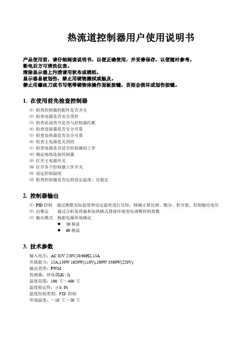
热流道控制器用户使用说明书产品使用前,请仔细阅读说明书,以便正确使用,并妥善保存,以便随时参考。
断电后方可清洗仪表。
清除显示器上污渍请用软布或棉纸。
显示器易被划伤,禁止用硬物擦拭或触及。
禁止用螺丝刀或书写笔等硬物体操作面板按键,否则会损坏或划伤按键。
1.在使用前先检查控制器⑴检查控制器的配件是否齐全⑵检查电源是否安全受控⑶检查此说明书是否与控制器匹配⑷检查连接器是否安全可靠⑸检查加热器是否安全可靠⑹检查主电源是关闭的⑺检查电源是否适合控制器的工作⑻确定地线连接控制器⑼打开主电源开关⑽打开各个控制器工作开关⑾设定控制温度⑿检查控制器是否达到设定温度,且稳定2. 控制器输出⑴PID控制通过测量实际温度和设定温度进行比较,精确计算比例、微分、积分值,控制输出电压⑵自整定通过分析加热器和加热模式排除环境变化调整控制参数⑶输出模式根据电源环境确定●50赫兹●60赫兹3. 技术参数输入电压:AC 85V-250V,50/60HZ,15A负载能力:15A,150W-1650W(110V),100W-3300W(220V)输出类型:PWM传感器:热电偶(K \ J)温度范围:100℃~400℃温度稳定性:±0.5%温度控制类型:PID 控制环境温度:-10℃~50℃4.面板布局1.指示灯:状态指示灯(STATE):软启动常亮,预整定1秒闪烁,自整定0.5秒闪烁,其他状态不亮。
输出指示灯(OUT):指示输出的的状态。
自动指示灯(AUTO):指示自动模式被选择。
等待指示灯(STANDBY):指示等待模式被选择。
手动指示灯(MANUAL):指示手动模式被选择。
2.数码管:PV数码管,红色,显示测量温度和参数代码。
SV数码管,红色,显示设定值和参数代码值。
3.按键::输入键:模式键:AUTO、STANDBY、MANUAL模式转换键:增加键:减小键5.操作模式通过按SEL键1秒钟以上可以进入以下模式。
⑴自动模式:正常的PID控制,在正常的设定值上。

type avta温控阀中文说明书
一、温控阀的工作原理:
热媒介质流过阀门,经过换热器把被加热介质升温。
温度传感器随着被加热介质的温度变化,将信号送至控制器,与设定温度比较运算后将4-20毫安或0-10伏信号送至执行器控制阀门的开度,使热媒介质流量发生变化。
温度的细微变化将使传感器作出响应,改变热媒介质流量,准确控制被加热介质的温度。
二、安装要求:
安装前请仔细阅读本使用手册,如有疑问请咨询专业技术人员。
不按规程安装操作都可能导致设备损坏或影响使用效果。
1、本产品在出厂前经过严格的检测,尽管如此,在安装前请务必进行检查。
2、请按订货及送货装箱单核实数量及型号。
3、请按上述数量配置进行检验,检查在运输过程中是否有损坏。
三、安装步聚:
1、阀体应水平安装在一次热媒的入口处,阀杆朝上,确保执行器可垂直于水平面安装。
2、阀体前应安装过滤器,且直接与阀体对接,选用高目数过滤器。
3、阀前后安装手动截止阀。
4、阀侧面应安装旁通,并安装手动截止阀。
5、若阀前蒸汽压力过高,应安装减压阀,将蒸汽调至设计或较佳工作范围内。