HT20便携式数字特斯拉计使用说明书
- 格式:pdf
- 大小:248.37 KB
- 文档页数:2
主要按键说明:
1:测量键:
按下进行磁场数据的测量。
2;上限键:
按下此键同时按下功能区的“设置/存储键”,此时“上限/设置”灯闪烁调节“设置调节”按钮可进行上限数据最大设置之后按下功能区的“设置/存储”此时已设置数据被存储。
3下限键
按下此键同时按下功能区的“设置/存储键”,此时“下限/设置”灯闪烁调节“设置调节”按钮可进行下限数据最大设置之后按下功能区的“设置/存储”此时已设置数据被存储。
4设置调节按钮;
进行上、下限设置数据的调节。
5上限设置:
超过已设置的上限数据时此灯亮。
6下限设置:
超过已设置的下限数据时此灯亮。
7合格:
测量数据为已设置的上限和下限之间此灯亮。
操作步骤;
1;连接电源线。
2;安装传感器。
3:按下后面板上的开、关键。
4:选择量程
5;选择直流/交流
当重复按直流/交流按键时,液晶显示会交替变化,表示测量直流磁场或交流磁场。
(开机默认为直流)
6:选择显示单位
当重复按显示单位转换按键时,显示单位会在MT和GS之间转换。
(开机默认为MT)7:置零;
如显示屏上显示不为0,可按调零/重置峰值按键使之为零。
8测量:
将传感器护套打开,使传感器有效位置(横向传感器)或(纵向传感器)紧密接触被测材料表面(直流磁场)或被测的磁场位置(空间交。
直流磁场)进行测量(测量时探头没有刻度的一面贴着被测物,金属探头则是无原点的一面贴着被测物),液晶显示即为被测磁场的大小。

特斯拉计操作手册 1概述简单介绍技术指标%20%—80%各部分名称及功能1、传感器插座:用于连接传感器和仪器。
2、LCD :液晶显示。
3、校准电位器:用于调节传感器的供电电流。
4、调零电位器:将传感器置于零磁场内,如有数值显示则调节调零电位器使显示为零。
5、校准与测量转换开关:将开关按下则由测量数据显示切换到显示传感器供电电流的数值。
6、量程转换开关:将开关按下则由20MT 切换到200MT 的量程。
7、电源开关:按下则导通。
8、外接9V 电源插孔:将外接点连接后则使用AC220V 工作。
9、电池盒:用于放置9V 叠层电池。
2操作方法装上电池,调整调零旋钮至显示为零。
按下20mT 量程转换开关。
把特斯拉计传感器头部的凹陷圆点垂直放置在地感器表面上方,其顶部与钢轨表面垂直距离110mm 。
显示的数值为该点的磁感应强度,此数值为mT 值,1mT =10Gs ,不得少于40Gs 。
仪器在测试完毕后,将电池盒中电池拿出。
12 3678 4 5 9特斯拉计3注意事项磁铁磁性比较强,检查、测量地感应器时要注意安全,尽量使手表、磁卡、呼机、手机等远离磁铁。
特斯拉计在校准状态时,如不能调至传感器的校准值,则恒流源系统出现故障,应首先检查电源工作电压是否正常,再进一步检查连接线及元器件。
当特斯拉计在测量状态时,如果调解状态不起作用,则调零系统出现故障,可检查供电电源是否正常。
运算放大电路是否损坏,显示表是否正常。
当特斯拉计在测量状态时,测量磁性体无读数,则应首先检查供电电源是否正常,其次是检查传感器是否损坏,接线是否断裂。
传感器不可受力、不可撞击、不可挤压,以免损害。
特斯拉计测试仪应避免在不符合使用环境条件下使用。
四、地面感应器的技术参数及检测标准1.地面感应器位于钢轨外侧,中心距钢轨中心200±20mm。
2.地感器主要技术参数:年衰减量<8‰,工作温度≤80°C。
3.测量地面感应器磁场强度采用特斯拉计,型号HT20A。
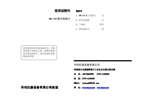
使用说明书HM100智能型数字特斯拉计华鸣仪器设备有限公司制造目录一般安全性概要 (3)前言 (4)第一章入门 (5)1.1使用装置前的准备 (5)1.2开始操作 (5)第二章特性功能 (6)2.1调零功能 (6)2.2采样保持功能 (6)2.3极性指示及超量程指示 (6)2.4单位切换功能 (6)2.5背光 (7)2.6电池电量及节能功能 (7)2.7量程自动切换及指示功能 (7)第三章工作说明3.1概述 (8)3.2工作原理 (8)3.3传感器使用方法 (9)3.4外观说明 (10)3.5主要技术参数 (10)3.6操作步骤 (11)第四章一般故障分析4.1一般故障解决 (13)4.2维修及注意点 (13)第五章保修条例 (14)联系信息 (15)一般安全性概要了解下列安全性预防措施,以避免受伤,并防止损坏本产品或与本产品连接的任何产品。
为避免可能的危险,请务必按照规定使用本产品。
只有合格的专业人员才能执行维修程序。
避免起火和人身伤害。
怀疑产品出现故障时,请勿进行操作。
如果您怀疑此产品已被损坏,可请合格的维修人员进行检查或与华鸣仪器设备有限公司联系。
请勿在潮湿的环境中操作。
请勿在易燃易爆的环境中操作。
请保持产品表面的清洁与干燥。
安全性术语和符号警告:警告性声明指出可能危害生命安全的行为。
注意:注意性声明指出可能导致此产品和其它财产损坏的条件和行为。
作测试时,必须用正确的功能和量程!前言非常感谢您购买HM100智能型数字特斯拉计您在使用本装置前,请仔细阅读本手册,本手册向您介绍了很多重要的信息和使用中应注意的事项。
阅读完后,请妥善保管,以便将来参考使用。
我们希望您对新设备完全满意,并希望能为您提供长久和有效的服务。
我们真诚地希望您以后继续选用我公司的产品!特别说明由于产品的不断更新发展,我们保留在没有事先通知的情况下,对本公司产品进行变动、修改的权力。
本手册虽经详细检查及校对,仍可能发生文字错误与技术描述疏漏的情况,恳请使用者及同行不吝赐教指正,以利于本手册的修改工作,力求手册内容的正确性。
1.0设备名称:特斯拉计
2.0设备型号:HT208
3.0生产厂商: 上海亨通磁电科技有限公司
4.0设备编号:BH94144
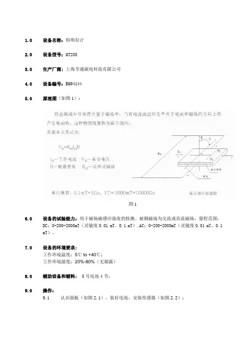
5.0原理图(如图1):
图1
6.0设备的试验能力:用于磁场磁感应强度的检测。
被测磁场为交流或直流磁场,量程范围:
DC:0-200-2000mT(灵敏度0.01 mT、0.1 mT),AC:0-200-2000mT(灵敏度0.01 mT、0.1 mT)。
7.0设备的环境要求:
工作环境温度:5℃ to +40℃;
工作环境湿度:20%-80%(无凝露)
8.0辅助设备和辅料: 5号电池4节;
9.0操作:
9.1认识面板(如图2.1),装好电池,安装传感器(如图2.2);
图2.1
图2.2
9.2按下面板上的“电源开关”,选择合适的量程。
如图3
图3
9.3将霍尔传感器保护套旋开,然后将霍尔传感器的有效位置靠近被测材料表面(如
图4.1,图4.2);
图4.1
图4.2
9.4选择峰值保持测量,读数(如图5);
图5
9.6仪器在测试完毕后传感器的护套旋上,将电池取出。
9.7测试过程中的注意点:
9.7.1对传感器的保护,在使用过程中,传感器不可受力,撞击或挤压;
9.7.2在测试时尽量减少外部磁场的影响,尽量不在可能产生磁场干扰的仪器附近进行产品的检测;
10.0 设备的维护保养
N.N.
11.0设备的点检
N.N.
12.0设备故障判断和排除
N.A.
13.0 设备的校验
N.A.
14.0 相关的文件表式
N.A.。
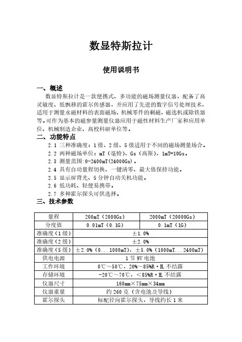
数显特斯拉计使用说明书一、概述数显特斯拉计是一款便携式、多功能的磁场测量仪器,配备了高灵敏度、低飘移的霍尔传感器,并应用了先进的数字信号处理技术,适用于测量永磁材料的表面磁场、机械零件的剩磁、磁选机或除铁器等。
可作为基本的磁参量测量仪器应用于磁性材料生产厂家和应用单位、机械制造企业、高校科研单位等。
二、功能特点2.1三种准确度:1级、2级、5级适用于不同的磁场测量场合。
2.2两种磁场单位:mT(毫特)、Gs(高斯),1mT=10Gs。
2.3测量范围:0-2400mT(24000Gs)。
2.4具有自动量程切换、一键清零、最大值保持功能。
2.5显示屏背光、5分钟自动关机功能。
2.6低功耗、轻便易携带。
2.7多种霍尔探头可供选择。
三、技术参数量程200mT(2000Gs)2000mT(20000Gs)分度值0.01mT(0.1G)0.1mT(1G)准确度(1级)±1.0%准确度(2级)±2.0%准确度(5级)±2.0%(0...1000mT),±5.0%(1000mT...2400mT)供电电源1节9V电池工作环境0℃~50℃,20%~85%R·H,不结露存储环境-20℃~70℃,<85%R·H,不结露仪器尺寸160mm×75mm×34mm仪器重量约260克(含电池及导线)霍尔探头标配径向霍尔探头,导线约长1米四、外观结构4.1外观4.2显示屏1、量程提示:当测量的磁场不足200mT时,默认量程为200mT;当超过200mT时,量程自动切换为2000mT。
2、磁场极性:当磁场方向是从霍尔传感器正面穿过时,屏幕显示为“N”;当磁场方向是从霍尔传感器背面穿过时,屏幕显示为“S”。
3、测量数值:霍尔传感器以数显的形式显示测量的磁场数值。
4、峰值模式:当屏幕显示“Peak”即为峰值模式,磁场数值显示一段时间内测量到的最大值并保持不变。
公司介绍北京翠海佳诚磁电科技有限责任公司(原翠海科贸公司)是一家专业从事全数字自动化测磁系统,高精度数字磁检测设备及数字磁场控制的科技型公司。
依托中科院的先进技术研发和生产高精度一维、二维和三维霍尔探头(带温度补偿)及多维高精度高分辨率测磁仪并通过ISO9001及IQNET国际体系认证,多项性能及参数均可达到国际先进水平,且多次被航天、军工、航海、科研及院校应用, 并受到广泛的好评。
我公司可以根据用户的需求,研发、生产多种测磁系统,包括多点阵列磁扫描系统和工业自动化检测系统、远程有线与无线控制系统、磁屏蔽系统、地磁补偿系统和特种高斯计、磁通门计、高精度磁场控制平台、计量检定系统(我公司使用的精度为:读数的±0.002%——±0.0002%)、多维磁场分析扫描系统、多维电机磁场测试分析系统、多极磁环测试系统、地磁屏蔽测磁系统、霍尔效应测试系统、线圈及电磁铁等等定制产品,同时代理国际尖端测磁仪器公司产品。
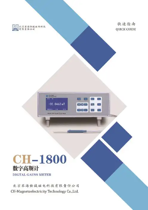
地理位臵地址:北京市海淀区丰豪东路9号院中关村集成电路设计园2E-409电话:************400-139-1007传真:************网址:内容摘要CH-1800简介 (1)快速入门 (2)按键功能及显示介绍 (4)后面板定义 (5)探头介绍 (6)CH-1800简介CH-1800全数字高斯计/特斯拉计是北京翠海佳诚磁电科技有限责任公司设计并制造的用于测量磁感应强度/磁通量密度的极高精度高分辨率全智能化仪器。
可搭配我公司生产的多种一维高斯计探头完成高低温、极小间隙、定距测量等多种环境的测量任务。
参数快速入门检查和开封首先请检查运输包装是否存在外部损伤和部件缺失,如果损伤或缺失比较明显,请尽快与运输商和我公司联系。
打开运输包装,依据内附包装清单确认仪器、传感器、附件和手册是否齐全,并查找是否存在损伤,丢弃包装物之前请务必清点所有提供的部件。
如果存在仪器或部件的运输损伤,撰写并尽快向运输商和保险公司发送正当的索赔单,并通知北京翠海佳诚磁电科技有限责任公司。
Table of ContentsTitle PageOverviewInspectionSafety InformationRules For Safe Operation International Electrical Symbols The Meter StructureFunctional ButtonsDisplay SymbolsMeasurement OperationA. Measuring ResistanceB. Capacitance MeasurementC. Diode and Continuity TestD. Transistor hFE Measurement General SpecificationsAccuracy SpecificationsA. Resistance TestB. Capacitance TestC. Continuity & DiodesD. TransistorMaintenanceA. General ServiceB. Replacing the BatteryC. Replacing the Fuse 3 4 5 6 8 9 9 10 11 11 13 15 17 18 19 19 20 20 21 22 22 23 2412OverviewThis Operating Manual covers information on safety and cautions. Please read the relevant information carefully and observe all the Warnings and Notes strictly.To avoid electric shock or personal injury, read the “Safety Information” and “Rules for Safety Operation”carefully before using the Meter.Digital Capacitance Meter Model 72-8150 (hereafter referred to as “the Meter”) is a 3 1/2 digits with steady operations, fashionable design and highly reliable hand-held measuring instrument. It will measure resistance, transistor hFE and test diodes. It will also test continuity with an audible buzzer.The Meter has a broad capacitance measurement range and precise accuracy. It can be used in measuring the circuit designed capacitance of cable, switch and PCB layout.34InspectionOpen the package case and take out the Meter. Check the following items carefully to see if any items are missing or damaged.Item Description Qty 123English Operating Manual Test Clip 9V Battery (NEDA1604, 6F22 or 006P)(installed)1 piece 1 pair 1 pieceIn the event you find any items missing or damaged, please contact your dealer immediately.Safety InformationThis Meter complies with the standards EMC EN61326.Use the Meter only as specified in this operating manual, otherwise the protection provided by the Meter may be impaired.In this manual, a Warning identifies conditions and actions that pose hazards to the user, and may damage the Meter or the equipment under test.A Note identifies the information that user should pay attention on.International electrical symbols used on the Meter and in this Operating Manual are explained on page 8.5To avoid possible electric shock or personal injury,and to avoid possible damage to the Meter or to theequipment under test, adhere to the following rules:Before using the Meter inspect the case. Do not use the Meter if it is damaged or the case (or part of the case) is removed. Look for cracks or missing plastic.Pay attention to the insulation around the connectors.Inspect the test clips for damaged insulation or exposed metal. Check the test clips for continuity.Replace damaged test clips with identical model number or electrical specifications before using the Meter.Do not apply voltage to the Meter.The rotary switch should be placed in the correct position and no change of range made during measurement, to prevent damage to the e the proper terminals, function, and range for your measurements.Do not use or store the Meter in an environment of high temperature, humidity, explosive, inflammable and strong magnetic field. The performance of the Meter may deteriorate after dampened.Disconnect circuit power and discharge all high-voltage capacitors before testing resistance,continuity, capacitance or diodes.Replace the battery as soon as the battery indicator appears. With a low battery, the Meter might produce false readings that can lead to electric shock and personal injury.Remove test clips from the Meter and turn the Meter power off before opening the Meter case.l l l l l l l ll Rules For Safe Operation6When servicing the Meter, use only the same model number or identical electrical specifications replacement parts.The internal circuit of the Meter shall not be altered at will to avoid damage of the Meter and any accident.Soft cloth and mild detergent should be used to clean the surface of the Meter when servicing. No abrasive and solvent should be used to prevent the surface of the Meter from corrosion, damage and accident.The Meter is suitable for indoor use.Turn the Meter power off when it is not in use and take out the battery when not using for a long time.Periodically check the battery as it may leak after some time. If leakage is apparent, the battery should be immediately replaced to prevent damage to the Meter.l l l l l 7International Electrical Symbols89The Meter Structure (see figure 1)Functional Buttons1. LCD Display2. Capacitance Zero Adjustment Switch3. Transistor Jack4. Resistance, Diode and Continuity Buzzer Input Terminal5. Capacitance Input Terminal6. Small Value Capacitance Jack7. Rotary Switch .8. Power Button(figure 1)Below table indicated for information about the functional button operations.Button DescriptionPress the Power down to turn the Meter on. Pressthe Power again to turn the Meter power off.Power10Display Symbols(see figure 2)Data hold is active.pF, nF, F, mFMake sure the Low Battery Display is not on, terminals of the Meter.llTo avoid damage to the Meter or to the devices under test, disconnect circuit power and discharge all the high-voltage capacitors before measuring resistance. The resistance ranges are 20, 200, 2k, 20k, 200k, 2M, 20M, 200M and 2000M.To measure resistance, please connect the Meter as follows:Insert the red test clip into the terminal and the black test clip into COM terminal.Set the rotary switch to range.Connect the test clips across with the object being measured.The measured value shows on the display. 1.2.3.11Measurement OperationA. Measuring Resistance (see figure 3)(figure 3)When measuring at 20Ω and 200Ω range, the test clips can add 0.1 to 0.3Ω error to resistance. To obtain precise readings in low-resistance measurements, short circuit the input terminals beforehand and record the reading obtained (called this reading as X). (X) is the additional resistance from the test clips.Then use the equation:measured resistance value (Y) – (X) = precision readings of resistance.The Meter displays “1” when there is no input, for example, open circuit situation.For high resistance measurement (>1M Ω), it normally requires several seconds to obtain a stable reading.When resistance measurement has been completed,disconnect the connection between the testing clips and the circuit under test and remove the test clips from the input terminals of the Meter.l l l l 12NoteTo avoid damage to the Meter or to the equipment under test, disconnect circuit power and discharge all high-voltage capacitors before measuringcapacitance.The Meter’s capacitance ranges are:200pF, 2nF, 20nF,200nF, 2µF, 20µF, 200µF, 2mF and 20mF.To measure capacitance, connect the Meter as follows:Set the rotary switch to F measurement mode. If the value of capacitor to be measured is unknown, use the minimum measurement position 200pF and increase the range step by step until a satisfactory reading is obtained and the overload icon "1" is not showing.Insert the red test clip into the CAP + terminal and black test clip into the CAP – terminal. For small value capacitor measurement, insert the capacitor into the Small Value Capacitance Jack.When testing polarized capacitors, use the red test clip on the capacitor’s positive lead, and the black test clip on the capacitor’s negative lead. With non-polarized capacitors, either direction is acceptable.1.2.3.13B. Capacitance Measurement(see figure 4)(figure 4)Do not short the test clips to avoid the consumption of battery.To minimize the effect of capacitance stored in the test clips, the test clips should be as short as possible and use the Small Value Capacitance Jack when measuring small value of capacitance.When capacitance measurement has been completed,disconnect the connection between the test clips and the circuit under test and remove the test clips from the input terminals of the Meter.l l l When measuring small value capacitor, that is 200pF,2nF and 20nF, first open circuit the test clips or the Small Value Capacitance Jack, then turn the Capacitance Zero Adjustment Switch to adjust zero.The measured value shows on the display.4.5.14NoteTo avoid damage to the Meter or to the devices under test, disconnect circuit power and discharge all the high-voltage capacitors before measuring diodes and continuity.Testing DiodesUse the diode test to check diodes, transistors, and other semiconductor devices. The diode test sends a current through the semiconductor junction, and then measures the voltage drop across the junction. A good silicon junction drops between 0.5V and 0.8V.To test a diode out of a circuit, connect the Meter as follows:Insert the red test clip into the terminal and the black test clip into the COMterminal.Set the rotary switch to .For forward voltage drop readings on any semiconductor component, place the red test clip on the component’s anode and place the black test clip on the component’scathode.The display shows the diode forward voltage drop’s nearest value.1.2.3.15C. Diode and Continuity Test (see figure 5)(figure 5)In a circuit, a good diode should still produce a forward voltage drop reading of 0.5V to 0.8V; however, the reverse voltage drop reading can vary depending on the resistance of other pathways between the probe tips.Connect the test clips to the proper terminals as said above to avoid error display. The LCD will display “1”indicating open-circuit for wrong connection. The unit of diode is Volt (V), displaying the positive-connection voltage-drop value.When diode measurement has been completed,disconnect the connection between the test clips and the circuit under test and remove them from the input terminals of the Meter.●●●To test for continuity,connect the Meter as below:Insert the red test clip into the terminal and the black test clip into the COM terminal.Set the rotary switch to .Connect the test clips across with the object being measured.Buzzer beeps if it is less than or equal to 10Ω and buzzer will not beep if it is more than 100Ω.The Meter displays the value of the test resistance.The LCD displays “1” indicating the circuit being tested is open.When continuity test has been completed, disconnect the connection between the test clips and the circuit under test and remove them from the input terminals of the Meter.●●16NoteTesting for Continuity1.2.3.4.5.NoteTo measure transistor, set up the Meter as follows:Check that the transistor is PNP or NPN type.Insert the transistor to be measured to the corresponding Transistor Jack .The Meter displays the tested transistor’s nearest value.When transistor measurement has been completed,disconnect the connection between the test clips and the circuit under test and remove them from the input terminals of the Meter.l 17D. Transistor hFE Measurement (see figure 6)(figure 6)1.2.3.NoteFused Protection for capacitance Input Terminal: 0.315A,250V, fast type fuse, 5x20 mm.Maximum Display: Display: 1999.Measurement Speed: Updates 2-3 times /second.Polarity: Auto. (Display “-“ when negative)Overload: Display “1”Range: Manual RangingCapacitance range zero adjustment:The range around Temperature:Operating: 0o C~40o C (32oF ~104o F).Storage: -10o C~50o C (14o F ~122o F).Relative Humidity:75% @ 0o C - 30o C;50% @ 31o C - 40o C.Altitude:Operating: 2000 m.Storage: 10000 m.Battery Type:One piece of 9V NEDA1604 or 6F22 or 006P.Low Battery: Display Dimensions: 6.77" (H) x 3.27" (W) x 1.50" (D).Weight: Approximate 310g (battery included).Certification: , UL & CUL pending.l l l l l l l l l ll l l l l l 18General SpecificationsAccuracy: (a% reading + b digits), guarantee for 1 year.Operating temperature: 23o C 5o C.Relative humidity: <75%.Temperature coefficient: 0.1 x (specified accuracy) / 1o C.When measuring 20Ω and 200Ω range, the test clips can add 0.1 to 0.3Ω error to resistance. To obtain precise readings in low-resistance measurements, short circuit the input terminals beforehand and record the reading obtained (called this reading as X). (X) is the additional resistance from the test lead.Then use the equation:measured resistance value (Y) – (X) = precision readings of resistance l 19Accuracy SpecificationsA. Resistance TestRemarks:Overload Protection 0.315A, 250V, fast type fuse, 5x20 mmIf the Meter can not adjust to zero, you could use the tested values minus the open circuit value to get the correct measurement value.Measure of Capacitance: 1F=103mF = 106µF = 109nF = 1012pF●●●Diode:Open Circuit Voltage around 2.8V.ContinuityBuzzer beeps if it is less than or equal to 10Ω and buzzer will not beep if it is more than 100Ω.●●20Remarks:Remarks:The display value is the tested transistor’s nearest value (0~1000β).l 21Remarks:This section provides basic maintenance information including battery and fuse replacement instruction.Do not attempt to repair or service your Meter unless you are qualified to do so and have the relevant calibration, performance test, and service information.To avoid electrical shock or damage to the Meter, donot allow water inside the case.Periodically wipe the case with a damp cloth and mild detergent. Do not use abrasives or solvents.To clean the terminals with cotton bar with detergent, as dirt or moisture in the terminals can affect readings.Turn the Meter power off when it is not in use and take out the battery when not using for a long time.Do not store the Meter in a place of humidity, high temperature and strong magnetic field.l l l l 22MaintenanceA. General ServiceTo avoid false readings, which could lead to possibleelectric shock or personal injury, replace the battery as soon as the battery indicator “ ” appears.Turn the Meter power off and remove all connections from the terminals.Remove the screw from the battery compartment, and separate the battery compartment from the case bottom.Remove the battery from the battery compartment.Replace the battery with a new 9V battery (NEDA1604,6F22 or 006P)Replace the case bottom and battery compartment, and reinstall the screw.1.2.3.4.5.23B. Replacing the Battery(see figure 7)(figure 7)To replace the battery:To avoid injury due to electrical shock or arc blast,and to avoid damage to the Meter, use specified fusesONLY in accordance with the following procedure.To replace the Meter’s fuse:Turn the Meter power off and remove all connections from the terminals.Remove the screw from the battery compartment, and separate the battery compartment from the case bottom.Remove the screws from the case bottom, and separate the case top from the case bottom.Remove the fuse by gently prying one end loose, then take out the fuse from its bracket.Install ONLY replacement fuses with the identical type and specification as follows and make sure the fuse is fixed firmly in the bracket.Fuse 1: 0.315A, 250V, fast type fuse, 5x20 mm.Replace the battery compartment and the case top, and reinstall the screw.Replace the case bottom and case top, and reinstall the screws.1.2.3.4.5.6.7.24C. Replacing the Fuse (see figure 8)(figure 8)S C R E WFuse replacement is seldom required. Blown fuses are typically a result of improper use.** END **This operating manual is subject to change without notice.25Copyright 2006 Tenma Test Equipment. Tenma Test Equipment405 S. Pioneer Blvd.Springboro,Ohio 4506626。
SG-41/ SG-42型数字特斯拉计说明书本仪器是根据霍尔效应原理设计的台式数字式高斯计/特斯拉计。
它具有量程宽(10T)、分辨力(10μT)、性能稳定、读数清晰准确等特点。
该仪器由4 1/2位LED发光字符显示,电子线路部分具有0.05%的线性度, 仪表的准确度主要取决于霍尔元件的磁线性度与稳定性。
SG-41型高斯计/特斯拉计具有0.5%的准确度,而SG-42型高斯计/特斯拉计的准确度为1%。
本仪器具有模拟输出口,可外接示波器、函数记录仪或其他测量仪表,用以观察磁场的变化波形,间接测量交流磁场的平均值、有效值或峰值。
本仪器具有显示清晰、操作简便、性能可靠的特点。
可广泛用于空间磁场、磁性材料、磁性元件和装置的测量,也可作为磁感应强度的标准使用(应具有计量部门的检定证书)。
主要技术指标1.测量范围:分200mT、2T和10T三个量程2.显示位数: 4 1/2 位LED发光数码管3.采样速率: 2.5次/秒4.最高分辨力:10μT5.准确度:(在20℃±2℃的条件下、在20mT~1.6T的磁感应强度范内)SG-41型:准确度为0.5%(读数)±0.01%(满度)SG-42型:准确度为1% (读数)±0.01% (满度)6. 噪声:≤2个字7. 极性辨别:当显示为“+”值时,探头注明“ N”面,面对磁场“ N”极8. 模拟输出:1mV/mT9. 过载能力:外磁场过载不会引起仪器损坏,过载时,所有数字闪跳。
10.尺寸:(W×H×D)260×105×28711.重量:约 2 kg标配是1.4毫米厚,4毫米宽的测头。
磁力检测仪MBO-2000A上海锦川仪表设备有限公司使 用 说 明 书沪制1100013感谢您购买"上海锦川"系列数字特斯拉计/高斯计.本使用说明书简扼介绍了此机之各项功能,让您操作自如,请您在使用前仔细阅读本使用说明书.一.概述MBO-2000系列便携式磁力检测仪可用于测量直流磁场、交流磁场、辐射磁场、剩磁、地球磁场等等各类磁场的磁感应强度。
该仪器可以随身携带(150mm×70mm×30mm),量程范围宽,操作方便,液晶显示清晰,按键均采用国内最先进的触摸式按键,大大增强了其使用寿命和使用舒适度。
电源为六节5号干电池,可连续工作100多个小时,也可在市电的情况下使用稳压电源,小巧便携。
完善的质量保证,优质的售后服务,是您工作的理想选择。
特斯拉计是检测磁体磁感应强度的专用仪器,是磁性测量领域中用途最为广泛的测量仪器之一。
MBO便携式数字特斯拉计可用于测量直流磁场、扬声器、磁选机、永磁除铁器的工作磁场以及泄漏磁场,零部件机加工后的退磁剩磁场等各类磁场的磁感应强度。
该仪器可以随身携带,量程范围宽,操作方便,液晶显示清晰。
实际工作领域:1.永磁材料的表面磁场分布(即我们通常所说的测量表磁);2.磁路结构内的间隙磁场;3.通过永磁或直流电流产生磁场作用于吸取铁磁材料的设备所产生的磁场(例如:除铁器、磁选机、磁力吸盘、电磁铁、退磁器)等等;二.工作原理本系列仪器采用的是基于霍尔效应原理制成的传感器,即霍尔传感器。
传感器有横向、轴向二种,用户可根据需求选择或另配;电路采用低漂移的放大器以及高稳定度的供电电源、31/2液晶显示屏显示测量值。
(一)霍尔效应原理将金属或半导体薄片置于磁场中,当有电流通过时,在垂直于电流和磁场的方向上将产生电动势,这种物理现象称为霍尔效应。
霍尔效应原理的实质是固体材料中的载流子在外加磁场(B与固体材料垂直)中运动时,因为受到洛仑兹力(F B)的作用而使轨迹发生偏移,并在材料两侧(3.4)产生电荷积累形成垂直于电流方向的外加磁场方向的电场,最终使载流子受到的洛仑兹力与电场斥力相平衡(F B=Fe)从而在二侧建立起一个稳定的电势差即(1页)(二).传感器使用方法以横向传感器为例1、传感器测量方法被测磁场的磁力线方向垂直穿过传感器前端的霍尔元件(如右图)2、手持传感器测量磁场的图示及说明如右图所示,手握传感器,用传感器前端霍尔元件的凹面(即有小圆圈标识的一面)轻轻接触被测磁铁的表面或所测空间磁场位置。
冰箱中磁场保鲜技术的应用研究任猛; 左秋杰【期刊名称】《《家电科技》》【年(卷),期】2019(000)005【总页数】3页(P83-85)【关键词】磁场; 失重率; VC; 呼吸强度【作者】任猛; 左秋杰【作者单位】长虹美菱股份有限公司安徽合肥230001【正文语种】中文1 引言随着健康饮食观念深入人心,消费者对于食材新鲜度的要求也不断升高,为了保证食品的新鲜,冰箱保鲜技术研究逐渐深入,研究成果层出不穷。
如控氧保鲜、恒温保鲜、湿度保鲜等,研究重点回归到冰箱的本质,各大冰箱制造商都在保鲜方面发力。
前期研究结果发现:果蔬在磁场条件下储存,生物体内会产生生理甚至遗传方面的变化,这些变化统称为磁效应[1]。
具体原理为:果蔬营养成分消耗代谢主要为呼吸代谢。
而果蔬的呼吸代谢主要影响因素为代谢酶的活性以及果蔬内参与代谢活动的金属带电原子电子链传递[2]。
而酶中含金属离子,在外加磁场的作用下,酶的活性以及电子传递受到限制,导致代谢强度下降。
同时磁场作用下会导致微生物的代谢发生紊乱,可降低微生物对于果蔬的破坏[3],延长果蔬的货架期。
本文以冰箱为载体,研究磁场对于果蔬代谢强度的影响,确定磁场应用于冰箱中对于果蔬最佳的作用条件,进而达到提升冰箱保鲜能力的目的。
2 材料与方法2.1 实验材料实验选择新鲜的水果以及蔬菜作为实验材料,具体包括:西红柿、冬瓜、生菜。
在实验前,应去除烂叶,去除表面淤泥以及水分等。
同时进行分组处理。
实验仪器:冷藏冷冻箱(BCD-520WUP9B)、数字特斯拉计(HT20 上海亨通磁电科技有限公司)、电子天平(ME104 梅特勒-托利多仪器有限公司)、气体分析仪(PMA1000 北京纳克分析仪器有限公司)等。
2.2 实验方法果蔬经预处理后分组编号放入冰箱,每隔3天称重、测量呼吸强度并拍照记录果蔬感官变化。
其中失重率采用差重法,呼吸强度通过气体分析仪进行检测。
3 实验设计设计单因素实验,通过控制磁场的大小,研究磁场大小、处理时间与保鲜效果的关系,确定磁场最佳的作用条件。