SG-41 SG-42型数字特斯拉计说明书
- 格式:pdf
- 大小:219.35 KB
- 文档页数:1
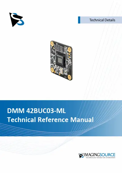
1.Quick Facts 32.Dimensional Diagrams 5 2.1DMM 42BUC03-ML Board Camera (5)3.I/O Connector 6 3.14-pin I/O Connector (6)3.1.1TRIGGER_IN (6)3.1.2STROBE_OUT (6)4.Spectral Characteristics 74.1Spectral Sensitivity - AR0134 (7)5.Camera Controls 8 5.1Sensor Readout Control (8)5.1.1Pixel Format (8)8-Bit Monochrome (8)5.1.1.15.1.2Frame Rate (8)5.1.3Partial Scan Offset (9)5.2Image Sensor Control (10)5.2.1Exposure Time (10)5.2.2Gain (10)5.3Trigger (10)5.3.1Trigger Mode (10)5.3.2Software Trigger (11)5.4Digital I/O (11)5.4.1General Purpose Input (11)5.4.2General Purpose Output (12)5.5Strobe (12)5.5.1Strobe Enable (12)5.5.2Strobe Polarity (12)6.Revision History 141Quick Facts2Dimensional Diagrams2.1DMM 42BUC03-ML Board Camera3I/O Connector3.14-pin I/O ConnectorRear view of camera1 max. 0.2A (ID) for open drain MOSFET!2 min. 3.5 mA driver strength required!3 G: Ground O: Output I: Input3.1.1TRIGGER_INThe TRIGGER_IN line can be used to synchronize the start of the exposure time with external events. The Trigger section describes in detail how the image sensor's behavior can becontrolled.The current input signal can also be read directly through the General Purpose Input feature.3.1.2STROBE_OUTThe STROBE_OUT line's main usage is to indicate the integration time of the image sensorwhich allows flashes, strobes or other light sources to be synchronized with cameraoperation. The line's behavior can be controlled through the Strobe controls.The output signal can also be directly controlled through the General Purpose Outputfeature.4Spectral Characteristics4.1Spectral Sensitivity - AR01345Camera ControlsThis section describes the parameters available for the DMM 42BUC03-ML camera.The actual name of the parameter depends on the driver technology used to access thecamera. Parameter names are listed for the most common ways to access the cameras:·UVC/V4L2 (on Linux, via uvcvideo)·IC Imaging Control (on Windows, via Device Driver for USB Cameras)5.1Sensor Readout Control5.1.1Pixel FormatThe pixel format defines the data type of the pixels transmitted to the computer. The bitsper pixel needed for a particular pixel format influence the required bandwith.The way the pixel format is controlled varies significantly among the driver technology used to access the camera:·When using the uvcvideo driver on Linux, the pixel format is defined by video4linux2.·When using IC Imaging Control, the pixel format is part of the video format - a parameterwhich combines pixel format, resolution and readout mode. For more information, referto the IC Imaging Control documentation sections on VideoFormat andVideoFormatDesc.The DMM 42BUC03-ML monochrome camera supports multiple pixel formats with variable bits-per-pixel settings. The names of the pixel formats and the way to select them dependson the driver used to control the camera. The following table contains a short overview ofall possible formats followed by a more detailed description.5.1.1.18-Bit MonochromeThis format transmits data using one byte for each pixel.UVC drivers see it with the FourCC Y800.The Device Driver for USB Cameras offers this pixel format as the Y800 video format.5.1.2Frame RateThe frame rate is specified in frames per second and determines the camera's operatingspeed.The way the frame rate is controlled depends greatly upon which driver technology is usedto access the camera:·When using uvcvideo on Linux, the frame rate is selected from a list of available framerates.·When using IC Imaging Control, the frame rate is selected from a list of available framerates through APIs such as Grabber::setFPS orICImagingControl.DeviceFrameRate.The range of available frame rates depends upon other camera settings such as well, pixelformat, resolution and readout modes.The following tables show the maximum frame rate for some combinations of pixel format and resolution.8-Bit Monochrome5.1.3Partial Scan OffsetIf the selected resolution is smaller than the sensor size, the part of the sensor that isactually read out can be specified by the Partial Scan Offset X and Partial Scan Offset Yparameters. By default, the camera automatically positions the offsets so that the center of the sensor is used.5.2Image Sensor Control5.2.1Exposure TimeThe Exposure Time parameter defines the time the camera opens its (electronic) shutterwhen it is taking an image.5.2.2GainThe Gain parameter defines the amplification that is applied to the image at sensor level.5.3TriggerThe trigger mode can be used to take images at very specific points in time which arespecified by an electrical signal connected to the TRIGGER_IN pin of the I/O connector of the camera.5.3.1Trigger ModeThe Trigger Mode parameter enables the trigger mode.5.3.2Software TriggerThe Software Trigger function can be used to simulate a trigger pulse, in turn causing oneimage to be exposed and delivered to the host computer.5.4Digital I/OThe One4All series has one digital input and one digital output. The digital input can beused as a Trigger input but the current status can also examined directly.The digital output can be configured as a Strobe output to signal the exact moment when the image sensor is sensitive to light so that external light sources can be synchronized to its operation cycle.5.4.1General Purpose InputThe General Purpose Input parameter allows the current status of the TRIGGER_IN pin.5.4.2General Purpose OutputThe General Purpose Output parameter controls the status of the STROBE_OUT pin.5.5StrobeThe strobe function controls the automatic generation of output pulses on theSTROBE_OUT pin which is synchronized to the image sensor's exposure time.5.5.1Strobe EnableThe Strobe Enable parameter enables the automatic generation of strobe pulses.5.5.2Strobe PolarityThe Strobe Polarity parameter can be used to invert the strobe pulse output.6Revision HistoryDMM 42BUC03-ML Technical Reference ManualAll product and company names in this document may be trademarks and tradenames of their respective owners and are hereby acknowledged.The Imaging Source Europe GmbH cannot and does not take any responsibility or liability for any information contained in this document. The source code presented in this document is exclusively used for didactic purposes. The Imaging Source does not assume any kind of warranty expressed or implied, resulting from the use of the content of this document or the source code.The Imaging Source Company reserves the right to make changes in specifications, function or design at any time and without prior notice.Last update: May 2023© 2023 The Imaging SourceAll rights reserved. Reprint, also in parts, only allowed with permission of The Imaging Source Europe GmbH.All weights and dimensions are approximate. Unless otherwise specified, the lenses shown in the context of cameras are not shipped with these cameras.Headquarters:The Imaging Source Europe GmbHÜberseetor 18, D-28217 Bremen, GermanyPhone: +49 421 33591-0North & South America:The Imaging Source, LLCSuite 470, 4600 Park Road, Charlotte, NC 28209, United StatesPhone: +1 877-462-4772Asia Pacific:The Imaging Source Asia Co., Ltd.3F., No. 43-7/8, Zhongxing RoadNew Taipei City, Xizhi District 221012, Chinese TaipeiPhone: +886 2-2792-3153。
磁悬浮原理实验目的1.观察自稳定的磁悬浮物理现象;2.深化学生对磁悬浮的原理的认识;3.培养动手观察思考能力,锻炼较强的耐心。
实验原理1. 磁学基本知识磁性:物质能吸引铁、钴、镍等金属的特性。
磁体:具有磁性的物体。
磁极:磁体上磁性最强的部分就是磁极。
当把两块磁铁放在一起相互靠近时,有时候互相吸引,有时候相互排斥。
现在人们都知道磁体有两个极,一个称N极,一个称S极。
同性极相互排斥,异性极相互吸引。
磁极是由环形电流元产生。
磁力是由于电荷运动所产生的基本力。
地球也是一个大磁体,它的两个极分别在接近地理南极和地理北极的地方。
因此地球表面的磁体,可以自由转动时,就会因磁体同性相斥,异性相吸的性质指示南北。
地球磁场的磁极和地理上的南北级方向正相反,而且和地球南北极并不重合,两者之间有一个11度左右的夹角,叫磁偏角。
此外地球磁场的磁极位置不是固定的,它有一个周期性变化。
地磁场强度很弱,在最强的两极其强度不到10-4(T), 平均强度约为0.6×10⁻⁴(T)。
2. 磁悬浮磁悬浮就是运用磁体“同性相斥,异性相吸”的性质,使磁体具有抗拒地心引力的能力悬浮起来,即“磁性悬浮”。
目前世界上有三种类型的磁悬浮。
一是以德国为代表的常导电式磁悬浮,二是以日本为代表的超导电动磁悬浮,这两种磁悬浮都需要用电力来产生磁悬浮动力。
而第三种,就是我国的永磁悬浮,它利用特殊的永磁材料,不需要任何其他动力支持。
(1)电磁悬浮系统(electromagnetic levitation ):简称EML技术。
它的主要原理是利用高频电磁场在金属表面产生的涡流来实现对金属球的悬浮。
将一个金属样品放置在通有高频电流的线圈上时,高频电磁场会在金属材料表面产生一高频涡流,这一高频涡流与外磁场相互作用,使金属样品受到一个洛沦兹力的作用。
在合适的空间配制下,可使洛沦兹力的方向与重力方向相反,通过改变高频源的功率使电磁力与重力相等,即可实现电磁悬浮。
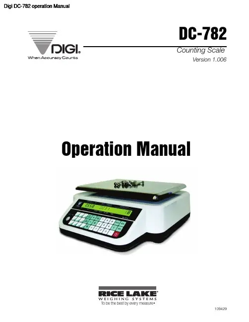
Digi DC-782 operation ManualDC-782Counting ScaleVersion 1.006Operation ManualT o be the best by every measure109429ContentsAbout This Manual (1)1.0 Introduction (1)1.1 Capacities and Resolutions . . . . . . . . . . . . . . . . . . . . . . . . . . . . . . . . . . . . . . . . . . . . . . . . . . . . . . . . 11.2 Modes of Operation . . . . . . . . . . . . . . . . . . . . . . . . . . . . . . . . . . . . . . . . . . . . . . . . . . . . . . . . . . . . . . 11.3 Keyboard and Display . . . . . . . . . . . . . . . . . . . . . . . . . . . . . . . . . . . . . . . . . . . . . . . . . . . . . . . . . . . . 21.3.1 Display Specifications . . . . . . . . . . . . . . . . . . . . . . . . . . . . . . . . . . . . . . . . . . . . . . . . . . . . . . . . . . . . . . 21.3.2 Indicator Lamps . . . . . . . . . . . . . . . . . . . . . . . . . . . . . . . . . . . . . . . . . . . . . . . . . . . . . . . . . . . . . . . . . . 21.3.3 Key Functions. . . . . . . . . . . . . . . . . . . . . . . . . . . . . . . . . . . . . . . . . . . . . . . . . . . . . . . . . . . . . . . . . . . . 32.0 Installation (5)2.1 Unpacking . . . . . . . . . . . . . . . . . . . . . . . . . . . . . . . . . . . . . . . . . . . . . . . . . . . . . . . . . . . . . . . . . . . . . 52.2 Repacking . . . . . . . . . . . . . . . . . . . . . . . . . . . . . . . . . . . . . . . . . . . . . . . . . . . . . . . . . . . . . . . . . . . . . 52.3 Setting Up . . . . . . . . . . . . . . . . . . . . . . . . . . . . . . . . . . . . . . . . . . . . . . . . . . . . . . . . . . . . . . . . . . . . . 52.4 Powering Up the DC-782. . . . . . . . . . . . . . . . . . . . . . . . . . . . . . . . . . . . . . . . . . . . . . . . . . . . . . . . . . 62.4.1 AC Power Source. . . . . . . . . . . . . . . . . . . . . . . . . . . . . . . . . . . . . . . . . . . . . . . . . . . . . . . . . . . . . . . . . 62.4.2 DC Battery Pack Replacement/Installation. . . . . . . . . . . . . . . . . . . . . . . . . . . . . . . . . . . . . . . . . . . . . . . 72.4.3 Battery Charging. . . . . . . . . . . . . . . . . . . . . . . . . . . . . . . . . . . . . . . . . . . . . . . . . . . . . . . . . . . . . . . . . . 82.4.4 Start-Up Screens . . . . . . . . . . . . . . . . . . . . . . . . . . . . . . . . . . . . . . . . . . . . . . . . . . . . . . . . . . . . . . . . . 82.5 Replacement Parts. . . . . . . . . . . . . . . . . . . . . . . . . . . . . . . . . . . . . . . . . . . . . . . . . . . . . . . . . . . . . . . 92.6 Block Diagram of Electrical Connections . . . . . . . . . . . . . . . . . . . . . . . . . . . . . . . . . . . . . . . . . . . . . 102.7 Physical Layout of Electrical Connections. . . . . . . . . . . . . . . . . . . . . . . . . . . . . . . . . . . . . . . . . . . . . 113.0 Configuration Settings (12)3.1 Putting the Scale in Maintenance Mode . . . . . . . . . . . . . . . . . . . . . . . . . . . . . . . . . . . . . . . . . . . . . . 123.2 Configuring Specification 141 and 142 Settings from the Scale Keyboard . . . . . . . . . . . . . . . . . . . . 123.2.1 Customer Specification (141 Settings). . . . . . . . . . . . . . . . . . . . . . . . . . . . . . . . . . . . . . . . . . . . . . . . . 123.2.2 Weight and Measurement Specifications (142 Settings). . . . . . . . . . . . . . . . . . . . . . . . . . . . . . . . . . . . 144.0 Calibration (17)5.0 Scale Operations (19)5.1 Counting Scale Accuracy. . . . . . . . . . . . . . . . . . . . . . . . . . . . . . . . . . . . . . . . . . . . . . . . . . . . . . . . . 195.2 Setting Tare Weights in Weighing Mode. . . . . . . . . . . . . . . . . . . . . . . . . . . . . . . . . . . . . . . . . . . . . . 195.2.1 One Touch Tare (When the Tare Weight is Unknown) . . . . . . . . . . . . . . . . . . . . . . . . . . . . . . . . . . . . . 205.2.2 Digital Tare (When Tare Weight is Known in Advance). . . . . . . . . . . . . . . . . . . . . . . . . . . . . . . . . . . . . 205.2.3 Tare Addition or Subtraction . . . . . . . . . . . . . . . . . . . . . . . . . . . . . . . . . . . . . . . . . . . . . . . . . . . . . . . . 205.3 Entering Unit Weights. . . . . . . . . . . . . . . . . . . . . . . . . . . . . . . . . . . . . . . . . . . . . . . . . . . . . . . . . . . . 205.3.1 Unit Weight Operation by Sampling. . . . . . . . . . . . . . . . . . . . . . . . . . . . . . . . . . . . . . . . . . . . . . . . . . . 215.3.2 Unit Weight Operation by Key Entry. . . . . . . . . . . . . . . . . . . . . . . . . . . . . . . . . . . . . . . . . . . . . . . . . . . 215.4 Operations Without Recalling an Item Code . . . . . . . . . . . . . . . . . . . . . . . . . . . . . . . . . . . . . . . . . . . 225.4.1 A Single Counting Operation - Without Recalling an Item Code. . . . . . . . . . . . . . . . . . . . . . . . . . . . . . 225.4.2 Part Accumulation or Subtraction and Negative Counting - Without Recalling an Item Code. . . . . . . . 225.5 Using Item Codes in Weighing Mode . . . . . . . . . . . . . . . . . . . . . . . . . . . . . . . . . . . . . . . . . . . . . . . . 245.5.1 Recalling Item Codes using Item Code Number . . . . . . . . . . . . . . . . . . . . . . . . . . . . . . . . . . . . . . . . . 245.5.2 Delete Item Memory . . . . . . . . . . . . . . . . . . . . . . . . . . . . . . . . . . . . . . . . . . . . . . . . . . . . . . . . . . . . . . 246.0 Scale Programming (25)6.1 Checking Memory Status. . . . . . . . . . . . . . . . . . . . . . . . . . . . . . . . . . . . . . . . . . . . . . . . . . . . . . . . . 256.2 Program Item Code, Tare Weight, Unit Weight, Setpoint 1 and 2. . . . . . . . . . . . . . . . . . . . . . . . . . .25i6.3 Program a General Setpoint . . . . . . . . . . . . . . . . . . . . . . . . . . . . . . . . . . . . . . . . . . . . . . . . . . . . . . 276.4 Programming a Preset Key . . . . . . . . . . . . . . . . . . . . . . . . . . . . . . . . . . . . . . . . . . . . . . . . . . . . . . . 276.5 Delete Item Memory . . . . . . . . . . . . . . . . . . . . . . . . . . . . . . . . . . . . . . . . . . . . . . . . . . . . . . . . . . . . 287.0 RS-232C Communication with PC (29)7.1 Connection . . . . . . . . . . . . . . . . . . . . . . . . . . . . . . . . . . . . . . . . . . . . . . . . . . . . . . . . . . . . . . . . . . . 297.2 General Specifications of the RS-232C Interface . . . . . . . . . . . . . . . . . . . . . . . . . . . . . . . . . . . . . . . 297.3 Setting the Scale Specifications for Communication to a PC . . . . . . . . . . . . . . . . . . . . . . . . . . . . . . 297.4 Communication Method . . . . . . . . . . . . . . . . . . . . . . . . . . . . . . . . . . . . . . . . . . . . . . . . . . . . . . . . . 307.4.1 Standard Stream Data Transmission (Continuous) . . . . . . . . . . . . . . . . . . . . . . . . . . . . . . . . . . . . . . . 307.4.2 Standard Manual Data Transmission. . . . . . . . . . . . . . . . . . . . . . . . . . . . . . . . . . . . . . . . . . . . . . . . . . 317.4.3 Standard Command Data Transmission . . . . . . . . . . . . . . . . . . . . . . . . . . . . . . . . . . . . . . . . . . . . . . . 327.5 Characters That Can Be Transmitted by RS-232C. . . . . . . . . . . . . . . . . . . . . . . . . . . . . . . . . . . . . . 327.6 RS-232C Data Transmission Formats . . . . . . . . . . . . . . . . . . . . . . . . . . . . . . . . . . . . . . . . . . . . . . . 33 1.0 Appendix (37)1.1 DC-782 Specifications. . . . . . . . . . . . . . . . . . . . . . . . . . . . . . . . . . . . . . . . . . . . . . . . . . . . . . . . . . . 371.2 DC-782 Error Message List. . . . . . . . . . . . . . . . . . . . . . . . . . . . . . . . . . . . . . . . . . . . . . . . . . . . . . . 382.0 DC-782 Limited Warranty (39)ii DC-782 Operation ManualThis is a “Table of Contents preview” for quality assuranceThe full manual can be found at /estore/catalog/ We also offer free downloads, a free keyboard layout designer, cable diagrams, free help andsupport. : the biggest supplier of cash register and scale manuals on the net。
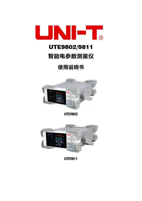
UTE9802/9811 智能电参数测量仪使用说明书UTE9802UTE9811前言感谢您购置优利德智能电参数测量仪,为了确保正确使用本仪器,在操作仪器之前请仔细阅读手册,特别是有关“安全事项”部分。
如已阅读完手册,建议您将此手册妥善保管,以便在将来使用过程中进行查阅。
版权信息UNI-T 优利德科技(中国)股份有限公司版权所有。
UNI-T 产品受中国或其他国家专利权的保护,包括已取得或正在申请的专利。
本公司保留更改产品规格和价格的权利。
UNI-T 保留所有权利。
许可软件产品由UNI-T及其子公司或提供商所有,受国家版权法及国际条约规定的保护。
本文中的信息将取代所有以前出版的资料中的信息。
UNI-T 是优利德科技(中国)股份有限公司(Uni-Trend Technology(China) Limited)的注册商标。
保固服务仪器自购买之日起保修期壹年,在保修期内由于使用者操作不当而损坏仪器的,维修费及由于维修所引起的费用由用户承担,仪器由本公司负责终身维修。
如果原购买者自购该产品之日一年内,将该产品出售或转让给第三方,则保修期应为自原购买者从UNI-T 或授权的UNI-T分销商购买该产品之日起一年内。
电源线及其他附件和保险丝等不受此保证的保护。
如果在适用的保修期内证明产品有缺陷,UNI-T可自行决定是修复有缺陷的产品且不收部件和人工费用,或用同等产品(由UNI-T决定)更换有缺陷的产品。
UNI-T作保修用途的部件、模块和更换产品可能是全新的,或者经修理具有相当于新产品的性能。
所有更换的部件、模块和产品将成为UNI-T的财产。
以下提到的“客户”是指据声明本保证所规定权利的个人或实体。
为获得本保证承诺的服务,“客户”必须在适用的保修期内向UNI-T通报缺陷,并为服务的履行做适当安排。
客户应负责将有缺陷的产品装箱并运送到UNI-T指定的维修中心,同时预付运费并提供原购买者的购买证明副本。
如果产品要运到UNI-T维修中心所在国范围的地点,UNI-T应支付向客户送返产品的费用。

数显特斯拉计使用说明书一、概述数显特斯拉计是一款便携式、多功能的磁场测量仪器,配备了高灵敏度、低飘移的霍尔传感器,并应用了先进的数字信号处理技术,适用于测量永磁材料的表面磁场、机械零件的剩磁、磁选机或除铁器等。
可作为基本的磁参量测量仪器应用于磁性材料生产厂家和应用单位、机械制造企业、高校科研单位等。
二、功能特点2.1三种准确度:1级、2级、5级适用于不同的磁场测量场合。
2.2两种磁场单位:mT(毫特)、Gs(高斯),1mT=10Gs。
2.3测量范围:0-2400mT(24000Gs)。
2.4具有自动量程切换、一键清零、最大值保持功能。
2.5显示屏背光、5分钟自动关机功能。
2.6低功耗、轻便易携带。
2.7多种霍尔探头可供选择。
三、技术参数量程200mT(2000Gs)2000mT(20000Gs)分度值0.01mT(0.1G)0.1mT(1G)准确度(1级)±1.0%准确度(2级)±2.0%准确度(5级)±2.0%(0...1000mT),±5.0%(1000mT...2400mT)供电电源1节9V电池工作环境0℃~50℃,20%~85%R·H,不结露存储环境-20℃~70℃,<85%R·H,不结露仪器尺寸160mm×75mm×34mm仪器重量约260克(含电池及导线)霍尔探头标配径向霍尔探头,导线约长1米四、外观结构4.1外观4.2显示屏1、量程提示:当测量的磁场不足200mT时,默认量程为200mT;当超过200mT时,量程自动切换为2000mT。
2、磁场极性:当磁场方向是从霍尔传感器正面穿过时,屏幕显示为“N”;当磁场方向是从霍尔传感器背面穿过时,屏幕显示为“S”。
3、测量数值:霍尔传感器以数显的形式显示测量的磁场数值。
4、峰值模式:当屏幕显示“Peak”即为峰值模式,磁场数值显示一段时间内测量到的最大值并保持不变。
公司介绍北京翠海佳诚磁电科技有限责任公司(原翠海科贸公司)是一家专业从事全数字自动化测磁系统,高精度数字磁检测设备及数字磁场控制的科技型公司。
依托中科院的先进技术研发和生产高精度一维、二维和三维霍尔探头(带温度补偿)及多维高精度高分辨率测磁仪并通过ISO9001及IQNET国际体系认证,多项性能及参数均可达到国际先进水平,且多次被航天、军工、航海、科研及院校应用, 并受到广泛的好评。
我公司可以根据用户的需求,研发、生产多种测磁系统,包括多点阵列磁扫描系统和工业自动化检测系统、远程有线与无线控制系统、磁屏蔽系统、地磁补偿系统和特种高斯计、磁通门计、高精度磁场控制平台、计量检定系统(我公司使用的精度为:读数的±0.002%——±0.0002%)、多维磁场分析扫描系统、多维电机磁场测试分析系统、多极磁环测试系统、地磁屏蔽测磁系统、霍尔效应测试系统、线圈及电磁铁等等定制产品,同时代理国际尖端测磁仪器公司产品。
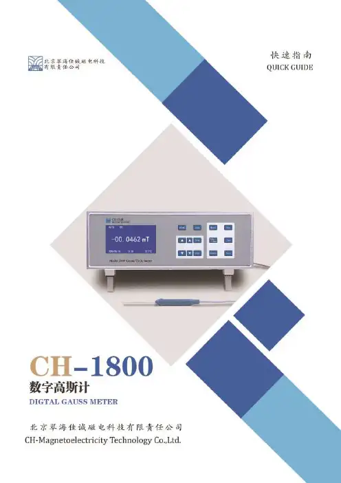
地理位臵地址:北京市海淀区丰豪东路9号院中关村集成电路设计园2E-409电话:************400-139-1007传真:************网址:内容摘要CH-1800简介 (1)快速入门 (2)按键功能及显示介绍 (4)后面板定义 (5)探头介绍 (6)CH-1800简介CH-1800全数字高斯计/特斯拉计是北京翠海佳诚磁电科技有限责任公司设计并制造的用于测量磁感应强度/磁通量密度的极高精度高分辨率全智能化仪器。
可搭配我公司生产的多种一维高斯计探头完成高低温、极小间隙、定距测量等多种环境的测量任务。
参数快速入门检查和开封首先请检查运输包装是否存在外部损伤和部件缺失,如果损伤或缺失比较明显,请尽快与运输商和我公司联系。
打开运输包装,依据内附包装清单确认仪器、传感器、附件和手册是否齐全,并查找是否存在损伤,丢弃包装物之前请务必清点所有提供的部件。
如果存在仪器或部件的运输损伤,撰写并尽快向运输商和保险公司发送正当的索赔单,并通知北京翠海佳诚磁电科技有限责任公司。

特斯拉计操作手册(总3页)本页仅作为文档封面,使用时可以删除This document is for reference only-rar21 year.March特斯拉计操作手册1概述1.1简单介绍特斯拉计也叫高斯计,可对永久磁材料的表面磁场、空间的直流磁场进行测量。
1-2技术指标量程范圉:0—20mT—200mT:基本误差:±1.0%:环境温度:5度一40 度;相对湿度:20%—80% (无凝露)。
1.3各部分名称及功能1、传感器插座:用于连接传感器和仪器。
2、LCD:液晶显示。
3、校准电位器:用于调节传感器的供电电流。
4、调零电位器:将传感器置于零磁场内,如有数值显示则调节调零电位器使显示为零。
5、校准与测量转换开关:将开关按下则山测量数据显示切换到显示传感器供电电流的数值。
6、量程转换开关:将开关按下则由20MT切换到200MT的量程。
7、电源开关:按下则导通。
8、外接9V电源插孔:将外接点连接后则使用AC220V工作。
9、电池盒:用于放置9V叠层电池。
2操作方法2.1装上电池,调整调零旋钮至显示为零。
2.2按下20 mT量程转换开关。
2.3把特斯拉计传感器头部的凹陷圆点垂直放置在地感器表面上方,其顶部与钢轨表面垂直距离HOmmo2.4显示的数值为该点的磁感应强度,此数值为mT值,lmT=10Gs,不得少于40Gso2.5仪器在测试完毕后,将电池盒中电池拿出。
3注意事项3.1磁铁磁性比较强,检查、测量地感应器时要注意安全,尽量使手表、磁卡、呼机、手机等远离磁铁。
3.2特斯拉计在校准状态时,如不能调至传感器的校准值,则恒流源系统出现故障,应首先检查电源工作电压是否正常,再进一步检查连接线及元器件。
3.3当特斯拉计在测量状态时,如果调解状态不起作用,则调零系统出现故障,可检查供电电源是否正常。
运算放大电路是否损坏,显示表是否正常。
3.4当特斯拉计在测量状态时,测量磁性体无读数,则应首先检查供电电源是否正常,其次是检查传感器是否损坏,接线是否断裂。
数字特斯拉计高斯计安全操作及保养规程1. 引言本文档旨在说明数字特斯拉计高斯计的安全操作规程以及保养方法,旨在帮助用户正确使用和保养数字特斯拉计高斯计,确保使用过程中的安全和准确性。
2. 仪器概述数字特斯拉计高斯计是一种用于测量磁场强度的仪器。
它具有高精度和高灵敏度的特点,适用于工业、科研以及其他领域的磁场测量。
以下是数字特斯拉计高斯计的主要规格:•测量范围:0.001 - 2000 mT•分辨率:0.001 mT•精度:±0.2%+1 digit•显示方式:数码显示•电源:9V 电池3. 安全操作规程正确的操作数字特斯拉计高斯计是确保安全和获得准确测量结果的关键。
以下是使用数字特斯拉计高斯计时的安全操作规程:3.1 仪器检查在使用之前,需要确保仪器处于良好的工作状态。
按照以下步骤进行仪器检查:1.检查电池电量,确保电池电量充足。
2.检查仪器外壳是否完好,无裂缝或损坏。
3.确保仪器显示屏幕无故障,并能正常显示数据。
3.2 使用准备在开始使用数字特斯拉计高斯计之前,需做好以下准备工作:1.选择一个安静的测量环境,避免外部磁场干扰。
2.关闭附近的磁性设备,以免干扰测量结果。
3.在无磁场的位置校零仪器。
3.3 测量操作执行以下步骤进行测量操作:1.打开仪器电源,并等待仪器自检完成。
2.将仪器垂直放置于待测磁场中心位置。
3.保持仪器与磁场平行,并靠近待测物体表面。
4.读取仪器显示屏上的磁场强度数值,并记录。
3.4 安全注意事项在使用数字特斯拉计高斯计时,请注意以下事项:•避免将仪器暴露于高温、潮湿、腐蚀性气体等环境中,以免损坏仪器。
•慎防仪器与尖锐物体接触,以免刮伤屏幕或损坏表面。
•使用过程中请禁止拆卸或改装仪器,以免对仪器造成损坏。
•使用完毕后,请及时关闭仪器电源。
4. 保养规程正确的保养能够延长数字特斯拉计高斯计的使用寿命并保持其准确性。
以下是数字特斯拉计高斯计的保养规程:1.定期清洁仪器表面,可使用干净柔软的布轻轻擦拭仪器。
SG-41/ SG-42型数字特斯拉计说明书本仪器是根据霍尔效应原理设计的台式数字式高斯计/特斯拉计。
它具有量程宽(10T)、分辨力(10μT)、性能稳定、读数清晰准确等特点。
该仪器由4 1/2位LED发光字符显示,电子线路部分具有0.05%的线性度, 仪表的准确度主要取决于霍尔元件的磁线性度与稳定性。
SG-41型高斯计/特斯拉计具有0.5%的准确度,而SG-42型高斯计/特斯拉计的准确度为1%。
本仪器具有模拟输出口,可外接示波器、函数记录仪或其他测量仪表,用以观察磁场的变化波形,间接测量交流磁场的平均值、有效值或峰值。
本仪器具有显示清晰、操作简便、性能可靠的特点。
可广泛用于空间磁场、磁性材料、磁性元件和装置的测量,也可作为磁感应强度的标准使用(应具有计量部门的检定证书)。
主要技术指标1.测量范围:分200mT、2T和10T三个量程2.显示位数: 4 1/2 位LED发光数码管3.采样速率: 2.5次/秒4.最高分辨力:10μT5.准确度:(在20℃±2℃的条件下、在20mT~1.6T的磁感应强度范内)SG-41型:准确度为0.5%(读数)±0.01%(满度)SG-42型:准确度为1% (读数)±0.01% (满度)6. 噪声:≤2个字7. 极性辨别:当显示为“+”值时,探头注明“ N”面,面对磁场“ N”极8. 模拟输出:1mV/mT9. 过载能力:外磁场过载不会引起仪器损坏,过载时,所有数字闪跳。
10.尺寸:(W×H×D)260×105×28711.重量:约 2 kg标配是1.4毫米厚,4毫米宽的测头。
HMI41 Indicator and HMP42/HMP46 ProbesThe Vaisala HUMICAP® Humidity Indicator HMI41 fitted with the Vaisala HUMICAP® Humidity and Temperature Probes HMP42 or HMP46 can be used for spot checking and field calibration applications.In addition to displaying the humidity and temperature readings, the HMI41 indicator calculates dew point and wet bulb temperature, absolute humidity and mixing ratio.The indicator has an easy-to-read two line liquid crystal display. The display units (metric or non-metric) are easily selected.These features, plus fast response time, high measurement accuracy and excellent stability, as well as the unique properties of the probe chosen – either the HMP42 or the HMP46 – makethe HMI41 indicator and HMP42/46 combination an ideal choice for the most demanding applications.Vaisala HUMICAP® Humidity and Temperature Probe HMP42The HMP42 probe can be used for spot checking humidity and temperaturein applications which require an extremely thin probe. Typically the probe is used for monitoring the drying of structures during construction or after water damage. It is ideal to be used when measuring in any tight places, in ducts or chambers or, for example, under a linoleum floor.The probe diameter is only 4 mm, allowing access into very small, tight, and hard-to-reach spaces.Vaisala HUMICAP® Humidity and Temperature Probe HMP46Typical applications for the HMP46 are plant maintenance, installation and inspection of air conditioning systems, production and storage areas and production processes. The HMP46 operates in full humidity range of0 ... 100 %RH. The temperature range is from -40 to +100 °C (-40 ... +212 °F). For short periods of time, the probe can withstand temperatures up to+180 °C (+356 °F).The HMP46 probe is solid and rugged. Its stainless steel probe is made to withstand rough handling in mechanically demanding applications. The probe’s long shaft can also reach otherwise unreachable places.High Performance Sensor The HMP42/46 probes incorporate Vaisala HUMICAP® Sensor. This sensor has high accuracy, excellent long-term stability and negligible hysteresis.In addition, the sensor is insensitiveto dust, particulate dirt and most chemicals.Features/Benefits▪RH measurement range0 ... 100 %RH▪T emperature measurement range -40 ... +100 °C(-40 ... +212 °F), with theHMP46 only for short periodsup to +180 °C (+356 °F)▪Calculates dew point, wet bulb temperature, absolute humidity and mixing ratio▪Versatile and easy-to-use▪Incorporates Vaisala HUMICAP® Sensor▪Excellent stability▪Data collection with serial line ▪NIST traceable (certificate included)▪Optional carrying case and calibration cable The Vaisala HUMICAP® Humidity Indicator HMI41 equipped with the Vaisala HUMICAP® Humidity and Temperature Probe HMP46 – a rugged stainless steel probe for mechanically demanding and high temperatureapplications.The Vaisala HUMICAP® Humidity Indicator HMI41 equipped with the Vaisala HUMICAP® Humidity and Temperature Probe HMP42 – an extremely thin probe allowing access into very small, tight, hard-to-reach spaces.HMI41 IndicatorCalculated variablesdew point temperature, absolute humidity,wet bulb temperature, mixing ratioResolution 0.1 %RH; 0.1 °C/°FPower supply4 batteries, type AA (LR 6)Battery operation time (alkaline batteries)72 h continuous use Auto-off functionOperating temperature -20 ... +60 °C (-4 ... +140 °F)Storage temperature -40 ... +70 °C (-40 ... +158 °F)Display two line LCD Housing material ABS plastic Housing classification IP53 (with connectors blocked)Weight (incl. batteries) 300 g Maximum measurement error of indicator at +20 °C humidity ±0.1 %RH temperature ±0.1 °C (±0.18 °F)HMP42 ProbeHumidityMeasurement range 0 ... 100 %RH Accuracy (incl. non-linearity, hysteresis and repeatability) at +20 °C (+68 °F)0 … 90 %RH ±2 %RH 90 … 100 %RH ±3 %RH Factory calibration uncertainty (+20 °C / +68 °F)0 … 15 %RH ±1 %RH 15 … 78 %RH ±1.5 %RH Temperature dependence of electronics ±0.05 %RH/°C Typical long-term stability better than 1 %RH per year Response time (90%) at +20 °C in still air 30 stemperatureMeasurement range HMP42 -40 ... +100 °C (-40 ... +212 °F)Temperature accuracy over measurement rangeHMP46 ProbeHumidityMeasurement range 0 ... 100 %RH, non-condensing Accuracy (incl. non-linearity, hysteresis and repeatibility) at +20 °C (+68 °F)0 … 90 %RH ±1 %RH 90 … 100 %RH ±2 %RH Factory calibration uncertainty (+20 °C / +68 °F)0 … 15 % RH ±1 %RH 15 … 78 %RH ±1.5 %RH Temperature DependenceTypical long-term stability better than 1 %RH per yearResponse time (90%)at +20 °C in still air w/sintered filter15 stemperatureContinuous measurement -40 ... +100 °C (-40 ... +212 °F)Short-term measurement -40 ... +180 °C (-40 ... +356 °F)Temperature accuracy at +20 °C (+68 °F) ±0.2 °C (±0.36 °F)Temperature accuracy over the measurement rangeTemperature sensor Pt100 RTD Class F0.1 IEC 607510.60.40.20-0.2-0.4-0.6∆°CT/°CTemperature sensor Pt100 RTD Class F0.3 IEC 60751210-1-21.50.5-0.5error %RH T/°CT/°CAccessoriesTransmitter calibration cables HMT330, HMT120/13025917ZZ HMT36025916ZZ HMM21019164ZZ HMD/W60/7019116ZZ Carrying case for HMI41 & HMP42/46plastic 210614aluminumMI70CASE2Serial communication cable 19446ZZ HMP42Calibration adapter HM37067Rubber sleeve set19809HMGeneral for ProbesCable length 1500 mm; extended spiral cable Operating temperature range for electronics -20 ... +60 °C (-4 ... +140 °F)Housing materialelectronics housing ABS plastic probe stainless steel Housing classification electronics IP65 (NEMA 4)HMP42 sensor protection steel grid 19867HM membrane, tube set (5 pcs)19858HM HMP46 sensor protection sintered filter 0195optional membrane filter, (max +80 °C / +176 °F) 10159HM plastic grid, (max +80 °C / +176 °F) 6221Weight HMP42200 g HMP46450 g Electromagnetic compatibility Complies with EMC standardEN61326-1, Portable Equipment.DimensionsDimensions in mm.HMI41HMP42HMP46ref. B211141eN-C ©Vaisala 2013this material is subject to copyright protection, with allcopyrights retained by Vaisala and its individual partners. allrights reserved. any logos and/or product names are trademarks of Vaisala or its individual partners. the reproduction, transfer, distribution or storage of information contained in this brochure in any form without the prior written consent of Vaisala is strictly prohibited. all specifications — technical included — are subject to change without notice.please contact us at/requestinfoScan the code for more information。
Operation ManualModel: RM-40EditionMonth Year 1stMay 2002 2nd3rd4th5thSHANGHAI TERAOKA ELECTRONIC CO., LTD.Ting Lin Industrial Development Zone, Jin Shan District, Shanghai P . R. China 201505Tel: +86-21-5723-4888 Fax: +86-21-5723-4090Web: Digi RM-40 operation ManualCONTENTS1. Important Information-----------------------------------------------------------------12. General Specification ---------------------------------------------------------------- -23. Setup----------------------------------------------------------------------------------------33.1 Overall Views----------------------------------------------------------------------33.2 Display Indicators----------------------------------------------------------- ------33.3 Key Layout-------------------------------------------------------------------- -----53.4 Terminal Pinter Specifications-------------------------------------------------73.4.1 General Specification-------------------------------------------------------73.4.2 Notes on Receipt Paper----------------------------------------------------73.5 Mode Change----------------------------------------------------------------------73.6 Specification Setting--------------------------------------------------------------83.6.1 Specification Entry-----------------------------------------------------------83.6.2 Customs Specification List-------------------------------------------------94. Programming (S) Mode--------------------------------------------------------- ----104.1 General Information-------------------------------------------------------------104.1.1 Key Function in Program Mode-----------------------------------------104.1.2 Data Files in Program (S) Mode----------------------------------------114.1.3 General Explanation-------------------------------------------------------124.2 Department Files---------------------------------------------------------------134.2.1 Program Department Files-----------------------------------------------134.2.2 Delete Department File---------------------------------------------------144.3 Main Group File------------------------------------------------------------------144.3.1 Program Main Group File-------------------------------------------------144.3.2 Delete Main Group File---------------------------------------------------154.4 PLU File----------------------------------------------------------------------------164.4.1 Messages on the display-------------------------------------------------164.4.2 Program PLU File (weighing item)-------------------------------------174.4.3 Program PLU File (non-weighing item)-------------------------------224.4.4 PLU Copy Function--------------------------------------------------------264.4.5 Delete PLU File-------------------------------------------------------------274.5 Free Format Setting-------------------------------------------------------------274.5.1 Programming procedure -------------------------------------------------274.5.2 Program Label Size--------------------------------------------------------284.5.3 Programming Parameter Of Print Items------------------------------284.5.4 Print Area And Print Position--------------------------------------------304.5.5 Program Print Items-------------------------------------------------------324.5.6 Free Format Copy Function----------------------------------------------354.5.7 Free Format Delete Function--------------------------------------------354.6.1 PLU Assignment------------------------------------------------------------364.6.2 Delete Assigned Preset Key---------------------------------------------364.7 Shop Name File------------------------------------------------------------------374.7.1 Program Shop Name File----------------------------------------------374.7.2 Delete Shop Name File-------------------------------------------------374.8 Special Message File-----------------------------------------------------------384.8.1 Program Special Message File---------------------------------------384.8.2 Delete Special Message File-----------------------------------------384.9 Ingredients File-------------------------------------------------------------------394.9.1 Program Ingredients File-------------------------------------------------394.9.2 Delete Ingredients File----------------------------------------------------394.10 Advertisement Message File--------------------------------------------------404.10.1 Program Advertisement File------------------------------------------404.10.2 Delete Advertisement File---------------------------------------------404.11 Vender File------------------------------------------------------------------------414.12 Program Data And Time-------------------------------------------------------414.13 Logo File Setting-----------------------------------------------------------------424.13.1 Pre-programming Logo Data------------------------------------------424.13.2 Program Display & Function Keys-----------------------------------424.13.3 Programming Order-----------------------------------------------------434.13.4 Program Logo File-------------------------------------------------------434.13.5 Delete Logo File----------------------------------------------------------434.14 Place of Production File Setting----------------------------------------------444.14.1 Program Production of Place File------------------------------------444.14.2 Delete Production of Place File---------------------------------------444.15 Program/Skip Item Data--------------------------------------------------------454.16 Tax File Setting-------------------------------------------------------------------464.17 Text File-----------------------------------------------------------------------------474.17.1 Program Text File--------------------------------------------------------474.17.2 Delete Text File-----------------------------------------------------------474.18 Machine Setting------------------------------------------------------------------484.19 Volume Discount & Sales Price Print Function---------------------------484.20 Memory Status-------------------------------------------------------------------504.21 Alphabetic data entry in Program Mode------------------------------------515. Registration (R) Mode ---------------------------------------------------------------525.1 ON/OFF----------------------------------------------------------------------------525.2 Reset and Weighing Check---------------------------------------------------525.3 Tare Subtraction------------------------------------------------------------------525.3.1 One Touch Tare Subtraction---------------------------------------------525.3.2 Digital Tare Subtraction---------------------------------------------------535.4.1 PLU Call by PLU Key------------------------------------------------------535.4.2 PLU Call Up with Preset Key--------------------------------------------535.4.3 PLU Call by Numeric Key (Auto PLU Call) --------------------------535.5 Fix Operation----------------------------------------------------------------------545.5.1 Fix Tare by FIX Key-------------------------------------------------------545.5.2 Fix PLU by FIX Key--------------------------------------------------------545.5.3 Fix Unit Price by FIX Key-------------------------------------------------545.6 Operation Mode Change-------------------------------------------------------555.7 Receipt Mode---------------------------------------------------------------------555.7.1 Transaction Entries---------------------------------------------------------555.7.2 Subtotal Read---------------------------------------------------------------565.7.3 Percent Discount--------------------------------------------------------565.7.4 Amount Discount-----------------------------------------------------------575.7.5 Immediate Correction -----------------------------------------------------595.7.6 Non-add Number Print----------------------------------------------------595.7.7 Finalize sale------------------------------------------------------------------595.7.8 No-sale -----------------------------------------------------------------------605.8 Label Manual Mode-------------------------------------------------------------605.8.1 Single Transaction----------------------------------------------------------605.8.2 Multiple sales Transaction------------------------------------------------615.9 Label Pre-pack Mode-----------------------------------------------------------615.9.1 Weighing Item ---------------------------------------------------------------615.9.2 Non-weighing Item---------------------------------------------------------626. Read Report (X) Mode ----------------------------------------------------------636.1 Read Report--------------------------------------------------------636.1.1 Sales Daily / Periodical Read Report-------------------------636.1.2 Vender Daily / Periodical Read Report----------------------636.1.3 In Drawer Daily Read Report------------------------------------636.1.4 Department Daily / Periodical Read Report----------------646.1.5 Main Group Daily Read Report--------------------------------646.1.6 PLU Daily Read Report------------------------------------------656.2 Received-on-Account Payment---------------------------------------------656.3 Paid Out----------------------------------------------------------------------------667. Reset Report (Z) Mode --------------------------------------------------------------677.1 Reset Report----------------------------------------------------------------------677.1.1 Sales Daily / Periodical Reset Report---------------------------------67This is a “Table of Contents preview” for quality assuranceThe full manual can be found at /estore/catalog/ We also offer free downloads, a free keyboard layout designer, cable diagrams, free help andsupport. : the biggest supplier of cash register and scale manuals on the net。
Quadra-Chek®Digital ReadoutsKnow preciselyQuadra-Chek ®Digital Readouts Metronics is the world’spremiere developer of metrology software and digitalreadouts for measuring and inspecting 2D and 3Dgeometric components.Metronics Quadra-Chek systems are the standardcontrol interface on the precision measuring devicesof many of the world’s leading precision metrologyinstrument manufacturers.Quadra-Chek digital readouts support industries that call for precisemeasurement and inspection of 2D and 3D parts in single-sensorand multi-sensor environments. The products feature an intuitiveuser interface and simple, meaningful visual displays. Their designreflects a deep understanding of user needs and a uniform workprocess model that supports operators at every stage in themeasurement process. Metronics digital readouts lead theprecision inspection industry with innovations that improveoperator productivity, reduce errors and save time and money.You can’t make a more accurate choice.Quadra-Chek 100 Series Digital Readouts Flexible, compact and precise digital readouts for 1- to 4-axis measuring instruments. Ideal for measuring angular or linear dimensions. Can be used with inspec-tion tools including optical comparators,measuring microscopes and coordinate measurement machines.Quadra-Chek 200 Series Geometric Readouts Our original digital readouts with a fresh new interface and sleek design. A time-saving measurement tool with patented Measure Magic ™technology.Ideal for measuring 2D features. Can be used with inspection tools such as optical comparators, measuring microscopes and coordinate measurement machines.Integrate fullyVersatile instrument support Comprehensive instrumentinterfacesComplete digital readout and software-based solutions If you already have a Quadra-Chek product on your shop floor—on any metrology instrument—you can easily integrate our newest products. If you are just developing a dimensional inspection capability, no other company provides as broad a prod-uct offering to help you grow as your needs change. Best of all, Quadra-Chek products share measuring protocols and interface conventions across the Metronics product line, which accelerates training,promotes cross-training and improves measurement accuracy.Since our founding in 1983, Metronicshas led the industry in the developmentof measurement solutions for diversemeasuring platforms and modern digitalreadouts. The company is recognizedaround the world as a comprehensiveresource for encoder interfaces thatsupport both the newest tools and theexisting platforms of leading metrologyinstrument manufacturers. We provideencoder interfaces compatible with newand existing instruments from the world’sleading manufacturers.Quadra-Chek products solve 2D and 3D measurement problems across industries and manufacturing functions, from inex-pensive single-axis systems to versatile multi-axis, multi-probe platforms that expand in functionality as your measure-ment needs grow. The Quadra-Chek line includes Windows ®-based software solu-tions and geometric readouts, each with configuration options and complementary accessories that provide turnkey support for all of your precision measurement challenges.Metrology softwareDigital readoutsQC-100 (2D)QC-200 (2D)Video measuring machinesCoordinate measuring machinesOptical comparatorsMeasuring microscopesIntuitive interface design Powerful data management toolsQuadra-Chek products incorporate insights gained from ongoing human factors research. They simplify repetitive tasks, visualize measurement data, and expand the possibilities of dimensional inspection processes. Intuitive work process models and operator interface innovations extend programming, automation and measure-ment capabilities across instruments; advance new standards for ease-of-use; and reduce operator training time.›Windows®platform›Graphic user interface›Icon-based tools and toolbars›Color coding›Audio feedback›Contextual help›Intelligent, time-saving protocols›IrDA communicationIntegral communication tools enableoperators to record, store and analyzemeasurement data. Operators can selec-tively or historically document measure-ments in dimensioned photographs andschematic drawings, as well as transfermeasurement data efficiently amongmachines performing related tasks.Operators can also export data to onlinedatabases for offline analysis by managersand quality control specialists.›CAD export›SPC export›CNC control›Integrated databases›Custom reportingGlobal support networkMetronics field engineers, based in officeslocated all over the world, can assist in theonsite review of dimensional inspectionrequirements. Complete contact details areavailable online at .›United States›France›Germany›Italy›United Kingdom›Japan›KoreaMetronics develops world-class metrology software and geometric digital readouts. The Quadra-Chek product line provides unmatched support for single-axis and multi-axis dimensional measurement of 2D and 3D parts on both new and existing tool platforms.Quadra-Chek digital readouts and PC-based products integrate innovative user interface conventions, state-of-the-art ergonomics, powerful data import, export and analysis tools. All Metronics products are supported by an international team of field engineers.Design innovationRe-designed Quadra-Chek digital readouts incorporate a range of ergonomic and display interface innovations that advance new standards for ease of use.Base depth:7.5"Maximum height:7.5"Understand completelyInputReduce operator subjectivity andfatigue, and enhance productivity, throughthe use of optical edge detection andautomatic point entry.Programming Simplify difficult andrepetitive measurement sequences withrobust, easy to use programming tools.Create step-by-step part programs usinga simple self-teach mode to guide subse-quent measurements.Measurement Record desired featureand construction measurements quickly,easily and accurately with patented soft-ware features like Measure Magic®.Accelerate the measurement process withtools that automatically complete complexwork steps.Modern metrology is a complex sequence of measuring, recording,analyzing and reporting dimensional data. The conceptual model underlying Metronics digital readout design organizes the workflow to support operators at every stage of the measurement process.Data Management Manage measure-ment data in ways that reduce screenclutter, reveal meaningful informationpatterns and visualize the complexrelationships among measured features.Output Streamline communication among operators, management, dispersed depart-ments and quality control teams. Send measurement information to a variety of applications, printers or databases.Exchange formatted data easily with part-ners or colleagues throughout the companyand around the world.Intuitive displays View measurement data easily on a crisp, clear, bright, black-and-white LCD designed for the contemporary metrology shop floor. Tilt the display for multiple viewing angles.Consistent user interface Experience a proven interface consistent with otherQuadra-Chek products that ensures operator accuracy and reduces operator training time.Options Get the right tools for the job. Optional remote keypads, footswitches and printers help operators capture the precise measurement data more conveniently while streamlining the work process.Sound feedback Listen for helpful sound feedback from a powerful built-in speaker.Different sound cues prompt operator action without interrupting work flow, speeding data entry.Auto repeat (QC-200) Measure features and print the results on the fly. Improve productivity and recordkeeping, and share information throughout the company and around the world.Foreign languages (QC-200) Communicate in five different languages. The QC-200 software accommodates English, Spanish, Italian, German, and French operators.Context-sensitive help (QC-200) Decrease training time and costs with graphics-rich,context sensitive help that guides shop floor personnel through Quadra-Chek interface conventions.ArchitectureThe powerful, familiar architecture of Quadra-Chek digital readoutsempowers operators during every step of the measurement process.Optical edge detection Achieve higher throughput, more accurate measurements, and more consistent data with optical comparators using optical edge detection. Automatic point entry reduces operator subjectivity and fatigue.4-axis capability (QC-200) Use Quadra-Chek to measure up to four axes per part. Quickly and accurately determine measures for X, Y , Z and Q (an integrated rotational axis for angular measurement).Measure Magic ®To measure, simply probe points and click. Quadra-Chek metrology software detects, without operator intervention, the feature type being measured. With this patented feature, operators can inspect multiple features without taking their eyes off the part which speeds throughput, improves accuracy and reduces user fatigue.Intersections and constructions (QC-200) Obtain essential intersection and construction results by selecting from the list of previously measured features, complete with graphics.Data cloud (QC-200) Improves the presentation of measurement data with graphic displays of measured features that reinforce operator comprehension by visualizing complex data sets.Geometric tolerancing (QC-200) Use Quadra-Chek’s unique graphic representations to instantly view pass/fail performance details for critical part dimensions.Results Display important measurement data in an uncluttered, comprehensive display.Input and MeasurementPatented features reduce repetitive measures and simplify complexwork steps.Quadra-Chek digital readouts feature an easy-to-use programminginterface that helps streamline difficult and repetitive measures.ProgrammingProgramming Intuitive tools simplify the creation of programs that automate repetitivetasks, reducing subjectivity and enhancing productivity.Part programming(QC-200) Quickly and easily create, edit and run part programs.Program a measurement sequence once and run it back as often as you need. Measurethe same number of points per feature, in the identical sequence, part after part.Measure guide(QC-200) Visual cues guide each feature measurement of a part, exactlyand repeatably, to assure complete and consistent data collection.Data management Metronics digital readouts allow operators to easily analyze and communicate measurements throughout the department and the entire organization.Print output Print measurement results using a serial or parallel printer in an easy-to-read 40- or 80-column format.Data output Parallel and serial ports make it easy to transfer data to PCs, networks and printers, while the IrDA port can be used to download measurement data to handheld PDAs and notebook computers.Data Management and OutputPrint outputOperators can easily format, analyze and communicate measurements throughout the company and around the world.Quadra-Chek 100 SeriesInputsUp to 4 axesExternal connections:FootswitchRemote keypadTouch ProbeRS-232C Serial portParallel portA flexible, compact and precise digital readout for 1- to 4-axis instruments. Ideal for measuring angular or linear dimensions. Can be used with inspection tools including optical comparators,measuring microscopes and coordinate measurement machines.Shown with optional remote control.Quadra-Chek 200 Series InputsUp to 4 axesExternal connections:FootswitchRemote keypadRS-232C Serial portParallel portOptical edge detectionOur original digital readout with a fresh new interface and sleekdesign. A time-saving measurement tool with patented MeasureMagic®technology. Ideal for measuring features of 2D features.Can be used with inspection tools such as optical comparators,measuring microscopes and video systems.MeasurementPointLineRadiusCircleAngle (vertex point)DistanceMinimum/maximum dist. between featuresForm informationMeasure Magic®Data cloudRotary axisIncremental/absoluteIntersectionsConstructionsCreatePresetForward/backward annotationFeature stampGeometric tolerancingProgrammingPart programmingMeasure GuideData Management and OutputOutput portsParallelSerial40-column printout80-column printoutAuto printSPC outputProduct comparisonQC-100QC-200QC-100QC-200 ArchitectureDisplayNumber of digits99LCD color B/W B/WDigit size0.45”0.45”Auto repeatContext-sensitive helpIrDA (optional)CorrectionLECSLECNLEC (optional)OrthagonalityC-scale (AR, HH)Footswitch inputRemote keypad inputSound feedbackSpeaker jackDate/time stampTilt adjustmentForeign languages(English, Spanish, Italian, German, and French)InputsOptical edge detection (optional)4-axisTouch probe inputGermanyACU-RITE GmbH Fraunhoferstr. 1D-83301 Traunreut GERMANY**************** www.acu-rite.deT: +49 8669 85 61 0 F: +49 8669 85 09 30 ItalyANILAM SRLStrada Borgaretto, 38 10043 Orbassano (TO) ITALY************** www.anilam.itT: +39-011-9002606 F: +39-011-9002466FranceACU-RITE SARL2, Avenue de la CristallerieBP 6892316 SEVRES CedexFRANCE************************T: +33.1.46 29 00 60F: +33.1.46 07 24 02KoreaRSF Electronics Ltd.1224-7, Sungseok-DongLisan-Ku, Koyang-Si, Kyunggi-DoKOREA************.krwww.rsf.co.krT: +82.31.977.4136.8F: +82.31.977.4139United KingdomACI EUROPE LIMITED16 Plover CloseInterchange ParkNewport Pagnell, BucksMK 16 9PS UNITED KINGDOM********************.ukT: +44.1908 514 500F: +44.1908 610 111JapanHEIDENHAIN K.K.Kudan Center Bldg. 10F4-1-7 Kudan-kitaChiyoda-kuTokyo 102-0073JAPANT: +81 3 32 34 77 81F: +81 3 32 62 2539Metronics Incorporated30 Harvey RoadBedford, NH 03110T: 603.622.0212F: 603.623.5623*******************Metronics®is the world’s premiere developer of metrology software and digital readouts formeasuring and inspecting 2D and 3D geometric parts. Metronics’ Quadra-Chek®systems are thestandard control interface of the world’s leading precision metrology instrument manufacturers.Metrology softwareQuadra-Chek 4000 Series 2- through 4-axis Microsoft Windows®-based measurement systemfor 2D applications.Quadra-Chek 5000 Series 2- through 4-axis Microsoft Windows®-based measurement systemfor 3D applications.Digital readoutsQuadra-Chek 100Series 1- through 4-axis, 1D digital readouts.Quadra-Chek 200Series 2- through 4-axis, 2D geometric readouts.Quadra-Chek 300Series 3- and 4-axis, 3D geometric readouts.Gage-Chek100Series 1- to 8-channel, metrology displays.Automation KitsStage Retrofits Bolt-on kits for microscope stages.Light Control Programmable control of up to eight channels of light sources.Indexers Stepper indexers to drive rotary stages and motorized zoom lenses.Stepper amplifiers Closed- or open-loop 2- and 3-axis stepper amplifier controllerswith limit switches.All trademarks, service marks and logos displayed are the property of their respective holders.©2000-2003 Metronics, Inc. Printed in the U.S.A. All rights reserved.11A10512 Rev 4 4/03 5M。
SG-41/ SG-42型数字特斯拉计说明书
本仪器是根据霍尔效应原理设计的台式数字式高斯计/特斯拉计。
它具有量程宽(10T)、分辨力(10μT)、性能稳定、读数清晰准确等特点。
该仪器由4 1/2位LED发光字符显示,电子线路部分具有0.05%的线性度, 仪表的准确度主要取决于霍尔元件的磁线性度与稳定性。
SG-41型高斯计/特斯拉计具有0.5%的准确度,而SG-42型高斯计/特斯拉计的准确度为1%。
本仪器具有模拟输出口,可外接示波器、函数记录仪或其他测量仪表,用以观察磁场的变化波形,间接测量交流磁场的平均值、有效值或峰值。
本仪器具有显示清晰、操作简便、性能可靠的特点。
可广泛用于空间磁场、磁性材料、磁性元件和装置的测量,也可作为磁感应强度的标准使用(应具有计量部门的检定证书)。
主要技术指标
1.测量范围:分200mT、2T和10T三个量程
2.显示位数: 4 1/2 位LED发光数码管
3.采样速率: 2.5次/秒
4.最高分辨力:10μT
5.准确度:(在20℃±2℃的条件下、在20mT~1.6T的磁感应强度范内)SG-41型:准确度为0.5%(读数)±0.01%(满度)
SG-42型:准确度为1% (读数)±0.01% (满度)
6. 噪声:≤2个字
7. 极性辨别:当显示为“+”值时,探头注明“ N”面,面对磁场“ N”极
8. 模拟输出:1mV/mT
9. 过载能力:外磁场过载不会引起仪器损坏,过载时,所有数字闪跳。
10.尺寸:(W×H×D)260×105×287
11.重量:约 2 kg
标配是1.4毫米厚,4毫米宽的测头。