工业产品试验大纲-DVP -11
- 格式:xls
- 大小:17.50 KB
- 文档页数:2
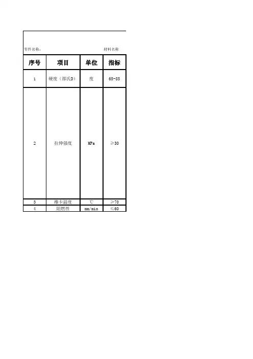
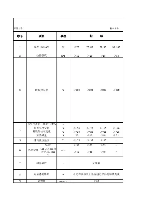
材料设计验证计零件名称:材料名称序号项目单位指标1硬度(邵氏D)度65-852拉伸强度MPa≥303维卡温度℃≥704阻燃性mm/min≤60材料设计验证计划和报告硬质PVC试验方法按GB2411《塑料邵氏硬度试验方法》,将厚度大于5mm的试片放在邵氏A(D)型硬度计上,若厚度不够,试样允许用两层,但不能超过二层叠合,并保证各层之间接触良好,试样大小应保证各个测量点与试样边缘距离不小于12mm,各测量点之间的距离不小于6mm,可以加工成50×50mm的正方形或者其他形状试样,至少测量5点,可在一个试样上或者多个试样上测定。
GB1040《塑料拉伸性能试验方法》,制作Ⅱ型哑铃状试样(见图1),将试样均匀地置于拉力试验机的上、下夹持器上,调节夹持器的移动速度至500mm/min,开动试验机,拉伸试样并跟踪试样的标记,记录试样拉伸至断裂过程中出现的最大力值,按下列公式分别计算拉伸强度和扯断伸长率:拉伸强度计算公式:σt=P/bd式中:σt——拉伸强度,Mpa;P——试样拉伸至断裂过程中出现的最大值,N;b——试样狭小平行部分的宽度,mm;d——试样的厚度,mm。
断裂伸长率计算公式:εt=[(G-G0)/G0]×100式中:εt——断裂伸长率,%;G——试样断裂时的标距,mm;G0——试样初始标距,mm。
按照GB/T1633《热塑性塑料维卡软化温度(VST)的测定》B50方法测定。
按照GB8410《汽车内饰材料的燃烧性能》,可从成品件上截取或者制成标准试样。
此项在零件有要求时测定。
参考标准GB2411GB1040GB/T1633GB8410。
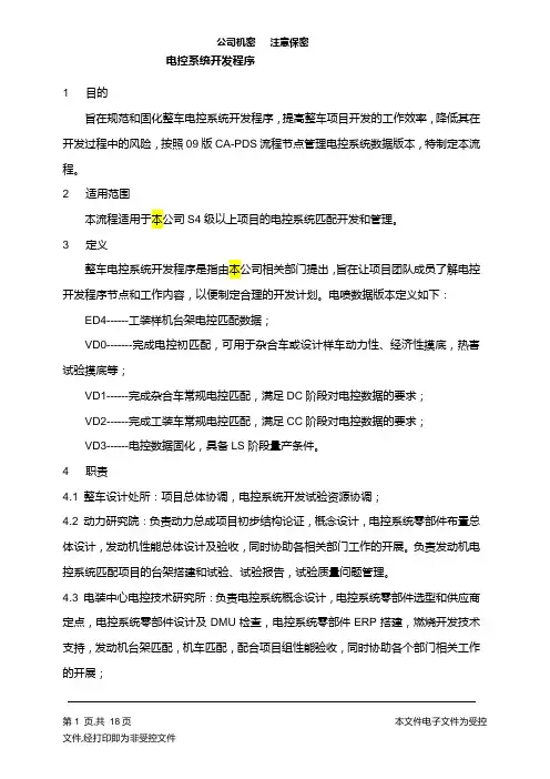
1 目的旨在规范和固化整车电控系统开发程序,提高整车项目开发的工作效率,降低其在开发过程中的风险,按照09版CA-PDS流程节点管理电控系统数据版本,特制定本流程。
2 适用范围本流程适用于本公司S4级以上项目的电控系统匹配开发和管理。
3 定义整车电控系统开发程序是指由本公司相关部门提出,旨在让项目团队成员了解电控开发程序节点和工作内容,以便制定合理的开发计划。
电喷数据版本定义如下:ED4------工装样机台架电控匹配数据;VD0-------完成电控初匹配,可用于杂合车或设计样车动力性、经济性摸底,热害试验摸底等;VD1------完成杂合车常规电控匹配,满足DC阶段对电控数据的要求;VD2------完成工装车常规电控匹配,满足CC阶段对电控数据的要求;VD3------电控数据固化,具备LS阶段量产条件。
4 职责4.1 整车设计处所:项目总体协调,电控系统开发试验资源协调;4.2 动力研究院:负责动力总成项目初步结构论证,概念设计,电控系统零部件布置总体设计,发动机性能总体设计及验收,同时协助各相关部门工作的开展。
负责发动机电控系统匹配项目的台架搭建和试验、试验报告,试验质量问题管理。
4.3 电装中心电控技术研究所:负责电控系统概念设计,电控系统零部件选型和供应商定点,电控系统零部件设计及DMU检查,电控系统零部件ERP搭建,燃烧开发技术支持,发动机台架匹配,机车匹配,配合项目组性能验收,同时协助各个部门相关工作的开展;4.4采购部:负责电装中心电控系统及其零部件供应商定点;4.5总院试验所:环境适应性试验、可靠性试验、排放试验的实施验收、冷启动实施验收等;4.6 整车性能处所:负责整车电控性能参数把控和验收,如驾驶性能验收等;5 工作要求及程序5.1重要输入品和交付物的要求:5.1.1方案及设计阶段报告:项目总体规划,发动机开发目标,项目一级网络图,发动机功能配置详细方案电控厂家配套通知;电控系统开发方案(开发目标\零部件技术方案\开发周期\成本分析),电控系统招标书/发动机排放目标/电控系统零部件/BOM表/电控系统开发二级网络图。
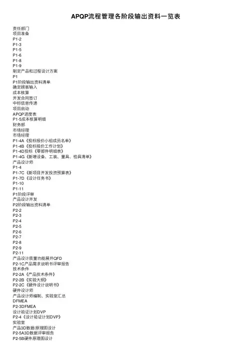
编号:QCX03.002奇瑞APQP 手册版本号:C/0页次:第1 页共51 页实施日期:2016.7.29奇瑞APQP 手册编制/日期:编制负责人:审核/日期:批准/日期:修订页编制/修订原因说明:①公司组织机构变更,更新各部门职责;②打破以往对供应商 APQP 输入、输出内容理解的局限性;对标合资并结合奇瑞实际进行了修订、梳理出适合奇瑞供应商APQP 管理的18 项质量活动;③从监控“节点通过率”转变为监控“完成率并识别风险”,落实“投产预警”持续管理;打破APQP 台阶式管理模式,强调供应商质量工作深入开展的连续性。
原章节号现章节号修订内容说明备注参与编制部门/人采购质量部/刘辉、崔雅心、何煌、许华芳、管仲丽、陈龙编制/修订部门/人采购质量部/刘顶成、岳峰、刘冬平参加评审C/0部门/人修订记录:版本号提出部门/人修订人审核人批准人实施日期备注A/0采购公司B/0质量保证部B/1质量保证部C/0采购质量部目录APQP 手册编制说明 (4)奇瑞与供应商APQP 监控职责 (5)供应商定点前的任务描述 (6)APQP 阶段评审 (7)APQP-18 项任务描述 (9)任务1:项目进度表/问题清单 (9)任务2:设计评审 (11)任务2:制造可行性 (13)任务3:工厂布置图&过程流程图 (14)任务4:DFMEA (15)任务5:检具/工装/设备审查 (17)任务6:试验大纲/DVP&R (20)任务7:PFMEA&防错 (22)任务8:控制计划 (24)任务9:样件质量控制 (26)任务10:设计外观质量 (28)任务11:过程验证 (31)任务12:早期生产遏制 (32)任务13:二级供应商 (34)任务14:PVS 成熟度确认 (35)任务15:2TP (37)任务16:PPAP (39)任务17:经验教训 (41)任务18:VDA6.3 质量体系要求 (43)附件一:项目采购质量管理手册 (45)1、采购质量项目节点状态报告 (45)2、质量唯一性清单 (45)3、风险逐层升级机制 (45)4、投产预警 (46)附件二:术语和定义 (48)APQP 手册编制说明此APQP 手册是奇瑞汽车供应商管理团队集体努力的结晶,致力于建立奇瑞汽车共同的APQP 过程。
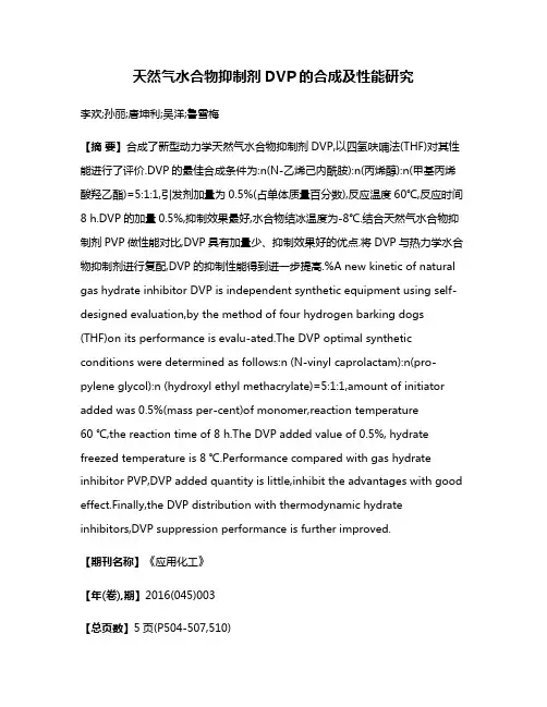
天然气水合物抑制剂DVP的合成及性能研究李欢;孙丽;唐坤利;吴洋;鲁雪梅【摘要】合成了新型动力学天然气水合物抑制剂DVP,以四氢呋喃法(THF)对其性能进行了评价.DVP的最佳合成条件为:n(N-乙烯己内酰胺):n(丙烯醇):n(甲基丙烯酸羟乙酯)=5:1:1,引发剂加量为0.5%(占单体质量百分数),反应温度60℃,反应时间8 h.DVP的加量0.5%,抑制效果最好,水合物结冰温度为-8℃.结合天然气水合物抑制剂PVP做性能对比,DVP具有加量少、抑制效果好的优点.将DVP与热力学水合物抑制剂进行复配,DVP的抑制性能得到进一步提高.%A new kinetic of natural gas hydrate inhibitor DVP is independent synthetic equipment using self-designed evaluation,by the method of four hydrogen barking dogs (THF)on its performance is evalu-ated.The DVP optimal synthetic conditions were determined as follows:n (N-vinyl caprolactam):n(pro-pylene glycol):n (hydroxyl ethyl methacrylate)=5:1:1,amount of initiator added was 0.5%(mass per-cent)of monomer,reaction temperature60 ℃,the reaction time of 8 h.The DVP added value of 0.5%, hydrate freezed temperature is 8 ℃.Performance compared with gas hydrate inhibitor PVP,DVP added quantity is little,inhibit the advantages with good effect.Finally,the DVP distribution with thermodynamic hydrate inhibitors,DVP suppression performance is further improved.【期刊名称】《应用化工》【年(卷),期】2016(045)003【总页数】5页(P504-507,510)【关键词】天然气水合物;动力学抑制剂;过冷度;结冰温度;THF【作者】李欢;孙丽;唐坤利;吴洋;鲁雪梅【作者单位】中国石油新疆油田分公司采油二厂,新疆克拉玛依 834000;川庆钻探工程有限公司地质勘探开发研究院,四川成都 610051;中国石油新疆油田分公司彩南油田作业区,新疆克拉玛依 834000;西南石油大学化学化工学院,四川成都610500;西南石油大学化学化工学院,四川成都 610500【正文语种】中文【中图分类】TQ317.4天然气开采、集输和加工过程中,由于温度、压力、流动速度等的变化,常在低温高压湍流处形成天然气水合物,导致装置运行异常,影响生产的顺利进行。
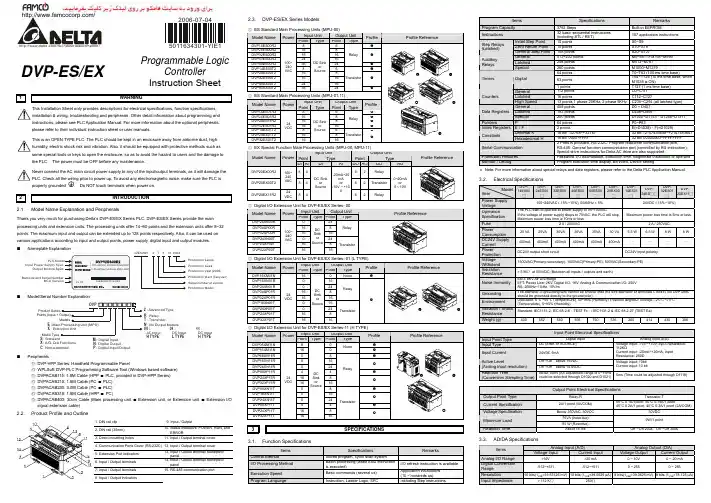
2006-07-045011634301-YIE1DVP-ES/EX Programmable LogicControllerInstruction Sheet1 WARNINGThis Installation Sheet only provides descriptions for electrical specifications, function specifications,installation & wiring, troubleshooting and peripherals. Other detail infromation about programming andinstructions, please see PLC Application Manual. For more information about the optional peripherals,please refer to their individual instruction sheet or user manuals.This is an OPEN TYPE PLC. The PLC should be kept in an enclosure away from airborne dust, highhumidity, electric shock risk and vibration. Also, it should be equipped with protective methods such assome special tools or keys to open the enclosure, so as to avoid the hazard to users and the damage tothe PLC. The power must be OFF before any maintenance.Never connect the AC main circuit power supply to any of the input/output terminals, as it will damage thePLC. Check all the wiring prior to power up. To avoid any electromagnetic noise, make sure the PLC isproperly grounded . Do NOT touch terminals when power on.2 INTRODUCTION2.1. Model Name Explanation and PeripheralsThank you very much for purchasing Delta’s DVP-ES/EX Series PLC. DVP-ES/EX Series provide the mainprocessing units and extension units. The processing units offer 14~60 points and the extension units offer 8~32points. The maximum input and output can be extended up to 128 points respectively. Also, it can be used onvarious applications according to input and output points, power supply, digital input and output modules.Nameplate Explanation32ES00R2T5140004Production seriesProduction weekProduction year (2005)Production plant (Taoyuan)Serial number of versionProduction ModelModel/Serial Number ExplanationDVP2E : Main Processing Unit (MPU)X : Extension UnitS : StandardX : A/D, D/A FunctionsM : Digital InputN : Digital OutputP : Digital Input/Output2 : Advanced TypeR : RelayT : TransistorN : No Output Module00 :H TYPE01 :L TYPE11 :H TYPEC : Non-extendedProduct SeriesPoints (Input + Output)ModelsModel Type AC Input DC Input DC InputPeripherals◎ DVP-HPP Series: Handheld Programmable Panel◎WPLSoft: DVP-PLC Programming Software Tool (Windows based software)◎ DVPACAB115: 1.5M Cable (HPP PLC, provided in DVP-HPP Series)◎ DVPACAB215: 1.5M Cable (PC PLC)◎ DVPACAB230: 3.0M Cable (PC PLC)◎ DVPACAB315: 1.5M Cable (HPP PC)◎ DVPACAB403: 30cm Cable (Main processing unit Extension unit, or Extension unit Extension I/Osignal extension cable)2.2. Product Profile and Outline1. DIN rail clip 9. Input / Output2. DIN rail (35mm)10. Status indicators: POWER, RUN, andERROR3. Direct mounting holes 11. Input / Output terminal cover4. Communication Ports Cover (RS-232C) 12. Input / Output terminal cover5. Extension Port indicators13. Input / Output terminal nameplatepanel6. Input / Output terminals14. Input / Output terminal nameplatepanel7. Input / Output terminals 15. RS-485 communication port8. Input / Output indicators2.3. DVP-ES/EX Series Models3SPECIFICATIONS3.1. Function SpecificationsItems Specifications RemarksControl Method Stored program, cyclic scan systemI/O Processing Method Batch processing (when END instructionis executed)I/O refresh instruction is availableExecution Speed Basic commands (several us) Application instructions(10 ~ hundreds us)Program Language Instruction, Ladder Logic, SFC Including Step instructionsItems Specifications RemarksProgram Capacity 3792 Steps Built-in EEPROMInstructions 32 basic sequential instructions(including STL / RET)107 application instructionsInitial Step Point 10 points S0~S9Zero Return Point 10 points S10~S19Step Relays(Latched)General Step Point 108 points S20~S127General 512+232 points M0~M511+M768~M999Latched 256 points M512~M767AuxiliaryRelaysSpecial 280 points M1000~M127964 points T0~T63 (100 ms time base)63 pointsT64~T126 (10 ms time base, whenM1028 is ON)Timers Digital1 points T127 (1 ms time base)General 112 points C0~C111Latched 16 points C112~C127CountersHigh Speed 13 points 1 phase 20KHz, 2 phase 5KHz C235~C254 (all latched type)General 408 points D0 ~ D407Latched 192 points D408~D599Data RegistersSpecial 200 points D1000~D1143、D1256~D1311Pointers P 64 points P0~P63Index Registers E / F 2 points E(=D1028),F(=D1029)Decimal K 16 bit: -32768~+32767 32 bit: -2147483648~+2147483647ConstantsHexadecimal H 16 bit: 0000~FFFF 32 bit: 00000000~FFFFFFFFSerial Communication2 Ports is provided. RS-232C: Program read/write communication port,RS-485: General function communication port (controlled by RS instruction);Special drive instructions for Delta AC drive are also supported.Protection Features Password, I/O examination, Execution time, Illegitimate instruction or operandMonitor / Debug Program execution time display, Bit/Word, Device setting*Note: For more information about special relays and data registers, please refer to the Delta PLC Application Manual.3.2. Electrical SpecificationsInput Point Electrical SpecificationsInput Point Type Digital Input Analog Input (EX)Input Type DC (SINK or SOURCE)Input Current 24VDC 5mAVoltage input: -10V~+10V, Input Resistance:112KΩCurrent input: -20mA~+20mA, InputResistance: 250ΩOff→On above 16VDCActive Level(Analog input resolution) On→Off below 14.4VDCVoltage input: 10bitCurrent input: 10 bitReaction Time(Conversion Sampling Time)About 10ms (An adjustment range of 0~15mscould be selected through D1020 and D1021)5ms (Time could be adjusted through D1118)Output Point Electrical SpecificationsOutput Point Type Relay-R Transistor-TCurrent Specification 2A/1 point (5A/COM) 55°C 0.1A/1point, 50°C 0.15A/1 point45°C 0.2A/1 point, 40°C 0.3A/1 point (2A/COM)Voltage Specification Below 250VAC, 30VDC 30VDC75VA (Inductive)Maximum Load90 W (Resistive)9W/1 pointReaction Time About 10 ms Off→On 20us On→Off 30us3.3. AD/DA SpecificationsAnalog Input (A/D) Analog Output (D/A)ItemsVoltage Input Current Input Voltage Output Current OutputAnalog I/O Range ±10V ±20 mA 0 ~ 10V 0 ~ 20 mADigital ConversionRange -512~+511 -512~+511 0 ~ 255 0 ~ 255Resolution 10 bits(1LSB=19.53125 mV) 10 bits (1LSB=39.0625 μA)8 bits(1LSB=39.0625 mV)8 bits (1LSB=78.125 μA)Input Impedance > 112 KΩ 250Ω-Analog Input (A/D)Analog Output (D/A)ItemsVoltage Input Current InputVoltage Output Current OutputOutput Impedance - 0.5Ωor lower Tolerance Carried Impedance - 1K Ω~2M Ω0~500ΩOverall Accuracy Non-linear accuracy: ±0.5% of full scale within the range of PLC operation temperature Maximum deviation: ±1% of full scale at 20mA and +10VReaction Time 2ms × channelsAbsolute Input Range±15 V±32 mA-Digital Data Format 2’s complementary of 16-bit, 10 Significant Bits2’s complementary of 16-bit, 8 Significant BitsAverage Function Provided-Isolation Method Isolation between digital area and analog area. But no isolation among channels.ProtectionVoltage output has short circuit protection but a long period of short circuit may cause internal wire damage and current output break.External Wiring DiagramCH0CH356K56K 28K28K250V+V-I+I--10V~+10V-20mA~+20mAVoltage Input Current Input GroundingGroundingCH0CH1V+V-I+I-GroundingAC Drive4INSTALLATION & WIRINGDimensionsModel Name (mm)HH1WW1W2 (H Type) W3(L Type)DVP14ES00(01)[11]R2/T2 100 95 99 104 82 50 DVP24ES00(01)[11]R2/T2 100 95 150 155 82 50DVP32ES00(01)[11]R2/T2 100 95 150 1558250DVP40ES00R2/T2 100 95 150 155 82 - DVP60ES00[11]R2/T2 90 85.5 180.5 185 89.6 - DVP20EX00[11]R2/T2 100 95 150 155 82-Terminal WiringPLC Mounting Arrangements and Installation NotesDIN Rail InstallationThe DVP-PLC can be secured to a cabinet by using the DIN rail that is 35mm high with a depth of 7.5mm. When mounting the PLC on the DIN rail, ensure to use the end bracket to stop any side-to-side motion of the PLC, thus to reduce the chance of the wires being pulled loose. On the bottom of the PLC is a small retaining clip. To secure the PLC to the DIN rail, place it onto the rail and gently push up on the clip. To remove it, use a slotted screwdriver, place it on the groove of the retaining clip and press gently, then pull down on the retaining clip and gently pull the PLC away from the DIN rail. For heat dissipation,ensure to provide a minimum clearance of 50mm between the unit and all sides of the cabinet. (as the figure shown below)Direct mounting : Use the specified dimensions and install with M4 screws.Wiring1. Please use O-type or Y-type terminals for I/O wiring terminals. The specification for theterminals is shown as the figure on the left. PLC terminal screws should be tightened to between 5~8 kg-cm (4.3~6.9 in-lbs). Only can use 60/75°C copper conducting wire. 2. DO NOT wire to the No Function terminals ‧ . I/O signal wires or power supply should not run through the same multi-wire cable or conduit.3. When tightening the screws and performing the wiring, please avoid that metallic particles fell into PLC. After completing wiring, please remove the label which is used to obstruct the metallic particles on the ventilation hole for well heat dissipation.Installation NotesIncorrect installation may result in a PLC malfunction or premature failure of the PLC. Ensure to observe the following items when selecting a mounting location.1. Do not mount the PLC in a location subjected to corrosive or flammable gases, liquids, or airborne dust or metallic particles.2. Do not mount the PLC in a location where temperatures and humidity will exceed specification.3. Do not mount the PLC in a location where vibration and shock will exceed specification. Power Input WiringThere are two power inputs provided in DVP series PLC, AC input and DC input. Please pay particular attentionto the following notes:1. Connect the AC input (100VAC~240VAC) to terminals L and N. Any AC110V or AC220V connected to the +24V terminal or input points will permanently damage the PLC.2. The AC power inputs for the MPU and the I/O Expansion Unit should be ON or OFF at the same time.3. Please use wires of 1.6mm or above for the grounding of the MPU.4. If the power-cut time is less than 10ms, the PLC still operates unaffectedly. If the power-cut time is too long or the power voltage drops, the PLC will stop operating and all the outputs will be OFF. Once the power is restored, the PLC will return to operate automatically. (There are latched auxiliary relays and registers inside of the PLC, please be aware when programming.)20.4VDC~26.4VDC). When the voltage is lower than 17.5VDC, PLC will stop operating, all outputs will turn OFF and the ERROR LED will flash continuously.Safety WiringSince the PLC is in control of numerous devices, operation of either one device could affect the operation of other devices, therefore the breakdown of either one device would consequently be detrimental to the whole autoInput Point WiringThe input signal of the input point is the DC power DC input. There are two types of DC type wiring: SINK and SOURCE, defined as follows:◎ Definition ◎ Wiring◎ Practical Relay Output Wiring◎ Practical Transistor Output Wiring5TRIAL RUNPower Indication1. The “POWER” LED at the front of the MPU or the Extension Units will be lit (in green) if the power is on. If theindicator is not on when the MPU is powered up, it means that there is abnormal condition on the DC power supply of the PLC. It is thus necessary to check the wiring on terminals +24V and 0V. If the ERROR LED is blinking swiftly, it indicates that the +24V power supply of the PLC is insufficient. 2. The “LOW V.” LED on the Expansion Unit is an indication that the input power voltage is insufficient, thus all outputs of the expansion unit should be turned off.Operation and Test1. If the ERROR LED of the MPU is not blinking, use the peripheral device to give the RUN command, and theRUN indicator will then be on.2. HPP could be utilized to monitor the timer (T), the counter (C) and the data register (D) during operation, and moreover, to force the output contacts to conduct the On/Off action. If the ERROR LED is on (but not blinking), it indicates that the setting of the user’s program has exceeded the preset overtime limit, thus users have to double check the program and perform the On/Off function again. (The PLC is at this moment back to STOP status automatically).PLC Input/Output Reaction Time:The total reaction time from the input signal to the output operation is calculated as follows:Reaction Time = input delay time + program scan time + output delay timeInput delay time Default 10ms. Please refer to the usage of special registers D1020~D1021.Program scan time Please refer to the usage of special register D1010. Output delay timeRelay module: 10ms. Transistor module: 20~30us.6TROUBLESHOOTINGudge the errors by the indicators on the front panel. When errors occurred on DVP series PLC, please check: ☼ “POWER” LEDThere is a “POWER” LED at the front of the MPU. The “POWER” LED will be lit (in green) when the power in connected to MPU. If the indicator is not on when the MPU is powered up and with the input power being normal, it indicates that the PLC is out of order. Please have this machine replaced or repaired at a distributor near you. ☼ PLC “RUN” LEDIdentify the status of the PLC. When the PLC is in operation, this light will be on, and the user could thus use HPP or the editing program of the ladder diagram to give commands to make the PLC “RUN” or “STOP”. ☼ “ERROR” LEDIf an incorrect program is input to the MPU, or the instruction and the device exceed the allowable range, theindicator will blink. At this moment, the user should check the error code saved in the MPU data register D1004 to correct the program. Find out the cause of the error and modify the programs. Then, re-send the correct program to the MPU.If the ERROR LED is blinking swiftly, it suggests that the +24VDC power supply of the PLC is insufficient. Please check whether the power supply of 24VDC is normal or not.When the ERROR LED is on (not blinking), it indicates that the execution time of the program loop has exceeded the time-out setting (set by D1000). Please check the program loop or use ”WDT” instruction to solve the problem. When the ERROR LED is on, please power down the MPU and start up it one time, and then check if the RUN LED is off. If the RUN LED is not off, please check if there is any noise and interference and check if any conductive material falling into the PLC. ☼ “Input” LEDThe On/Off signals of the input point could be displayed through the “Input” LED. Also, the status signal of the input point could be monitored through the device monitoring function of HPP . As long as the input point is activated, the LED is on. Therefore, if an error is detected, please check HPP , the LED indicator and the input signal circuits. Please pay particular attention to check if an electrical switch with significant leakage current is used as it often results in the unexpected operation of input point. ☼ “Output” LEDOutput LED indicates if the output signals are on or off. Please check the following items when the LED On/Off indication does not correspond to the commands:1. Output contacts may be melted and stuck together due to a short circuit or current overload.2. Check wiring and verify that the screws are tight and secure.。
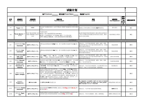
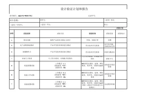
5高温工作试验将样品在65℃的温度条件下放置1小时后,再通电工作4小时后取出,室温下放置2小时后,进行通电测试;试验中无异常;试验后,功能基本无异常,可正常实现;外观无异常。
可程式烤箱远特实验室5H6温度循环试验将样品在-30℃的环境中放置1个小时,按下图规定的温度变化实施10 个周期,在此期间样品正常通电工作,10个周期完成后,在室温下放置2个小时,再进行通电实验;试验中无异常;试验后,功能基本无异常,可正常实现;外观无异常。
可程式恒温恒湿箱远特实验室81H7热冲击试验将样品放置在-30℃的恒温环境中1小时,取出并迅速将其放入85℃的恒温环境中放置1小时,按下图规定的方式循环100个周期,100周期完成后,在室温条件下放置2小时以上后,进行通电测试。
实验后,功能性能基本满足,无焊接断裂和裂缝。
可程式恒温恒湿箱&可程式烤箱远特实验室200H8恒温恒湿试验在温度45℃,湿度85%的环境下放置1小时后,接通电源持续工作96小时,最后在室温条件下放置2小时以上后进行测试。
试验中无异常;试验后,功能基本无异常,可正常实现;外观无异常。
可程式恒温恒湿箱远特实验室97H9温-湿度循环试验将样品放置在25℃的恒温、湿度65%的环境中2.5小时,样品必须正常工作,按下图规定对温湿度进行10个周期的调整,10个周期完成后,在室温条件下放置2小时以上后进行测试。
注:温度为55度时,湿度要求降低到85%;达到75度高温时,不加湿度试验中无异常;试验后,功能基本无异常,可正常实现;外观无异常。
可程式恒温恒湿箱远特实验室242.5H10结露试验将样品放入-5℃的环境中2个小时,然后取出放入35℃、湿度85%的环境中通电10分钟,循环4次。
实验中无异常;实验后产品基本功能性能保持良好;外观无异常;可程式恒温恒湿箱&可程式烤箱远特实验室9H11振动试验将样品放置到振动台进行上下、左右、前后以及快慢变换方向进行实验,周期如下表:试验中无异常;试验后,功能基本无异常,可正常实现;标识破损,可识别刻印,支架轻微弯曲等可接受振动试验机远特实验室12H12端子强度试验接插件端子,插入方向和拔出方向个施加98N(10kgf)的力1min。
dvp-plc 应用技术手册101一、简介DVP系列可编程逻辑控制器(PLC)是一种广泛应用于自动化领域的控制设备。
DVP-PLC应用技术手册101 是一本专门针对DVP系列PLC的应用技术手册,旨在帮助用户深入理解和掌握DVP系列PLC 的应用技术,从而更好地应用它们在自动化控制系统中。
二、基本概念DVP-PLC是一种具有逻辑控制功能的工业控制设备,其工作原理是通过输入信号的获取和逻辑运算来控制输出信号的状态,从而实现对工业生产设备的控制。
DVP-PLC具有多种输入输出接口,可以接入各种信号源,例如开关量信号、模拟量信号等,通过程序逻辑控制,实现对设备的自动控制。
三、应用领域DVP-PLC广泛应用于各种自动化控制系统中,例如工业生产线控制、智能楼宇控制、环境监测系统等。
由于其高可靠性、灵活性和易于编程等特点,DVP-PLC在自动化领域具有很大的市场需求。
四、技术特点1. 灵活的扩展性:DVP-PLC具有丰富的输入输出接口,可以通过扩展模块实现对更多信号源的连接,从而满足不同控制系统的需求。
2. 易于编程:DVP-PLC采用图形化编程软件,用户可以通过拖拽、连接元件来编写控制程序,无需深入了解底层硬件结构,降低了编程的难度。
3. 高性能:DVP-PLC具有快速的逻辑计算能力和稳定的控制性能,能够满足复杂控制系统的要求。
4. 可靠性高:DVP-PLC采用工业级的设计标准,具有抗干扰能力强、工作稳定可靠的特点,适用于恶劣的工业环境。
五、应用实例1. 工业生产线控制:DVP-PLC可以实现对工业生产线上各个设备的自动控制,包括输送带速度控制、工件定位、质量检测等功能。
2. 智能楼宇控制:DVP-PLC可以用于楼宇的照明控制、空调控制、电梯控制等,实现智能化的楼宇管理。
3. 环境监测系统:DVP-PLC可以用于监测环境中各种参数,如温度、湿度、气压等,并根据监测数据实现对环境设备的自动控制。
六、发展趋势随着自动化控制技术的不断发展,DVP-PLC作为自动化控制领域的重要设备,将会越来越广泛地应用于各个行业。
APQP 和PPAP 过程专业术语 (红色—重点注释;艳红色—评估中;蓝色—新增)DELPHI :在流程图的检验栏有以下四种注释:A = Automatic, or machine inspected (i.e. leak tester) A 代表自动检测或仪器检测(比如耐压、通断、针高等);M = Manually inspected by the operator (i.e. hand gage) M 代表操作工手动检测(比如工人用检测板进行针位检测);V = Visually inspected by the operator V 代表操作工目视检测(比如外观检测);Q = Quality Audit, control plan check Q 代表品质监控(比如IQC 、OQC 、IPQC 、SPC 控制等)AARAppearance Approval Report 外观批准报告 ADV Analysis/Development/Validation 分析/开发/验证ADV-DV ADV Design Validation A D V 设计验证A/D/V P&R Analysis/Development/Validation Plan and Report, This from is used to summarize the plan and results for validation testing. Additional informationCan be found in the GP-11procedure. 分析/开发/验证计划和报告AECAdditional Engineering Changes 附加工程更改 ADV-PV ADV product Validation A D V 产品验证AIAGAutomotive Industries Action Group, an organization formed by General Motors,Ford and Daimler Chrysler to develop common standards and expectations for automotive suppliers.汽车工业行动集团APAdvanced Purchasing 先期采购 APO(General Motors) Asian Pacific Operations (通用)亚太分部 APQP Advanced Product Quality Planning 产品质量先期策划AQE Advanced Quality Engineer 先期质量工程师ASQE Advanced Supplier Quality Engineer 先期供应商质量工程师ANOVA Analysis of Variance 方差分析法ASDE Advanced Supplier Development Engineer 高级供应商开发工程师BOM Bill of Materials 材料清单BOP Bill of Process 过程清单CCAR Concern ed and Corrective Action Report 相关整改报告CARCorrective Action Request 整改需求 CFTCross function Team 多方论证小组 CMM Coordinate Measuring Machine 三坐标测试仪CPV Weekly Production Volume 周产能CPK Capability Index for a Stabile process 过程能力指数CR Customer Requirements 客户要求CM Commodity Manager 产品经理CCM Corporate Commodity Manager 公司产品经理CS Customer Satisfaction 客户满意度CS 1/2 Level 1/2 Controlled Shipping 1/2级受控发运CTS Component Technical Specifications 零件技术规范DFM/DFA Design for Manufacturability/Design for Assembly 可制造性/可装配性设计 DCP Dimension Control Plan (Dynamic Control Plan) 尺寸控制计划(动态控制计划) DOE Design of Experiment 试验设计DPV Daily Production Volume 日产量DVP&R Design Validation Plan and Report 设计验证计划和报告DV Design Validation 设计验证DRE Design Release Engineer设计发放工程师DFMEA Design Failure Mode and Effects Analysis设计失效模式及后果分析EWO Engineering Work Order 工程更改指令EDI Electronic Data Interchange 电子数据交换FE1,2,3 Functional Evaluations1,2,and 3 功能评估ES Engineering Specification工程规范EPC Early Production Containment 早期生产遏制FAI First Article Inspection 首件检验FCR Field Call of RateFE Function Evaluation 功能评估FTA Failure Tree Analysis 故障树状分析FTC First Time Capability 试生产能力FTQ First Time Quality 直通率(一次合格率)GR&R Gage Repeatability and Reproducibility 量具的重复性与再现性GD&T Geometric Dimensioning & Tolerancing 几何尺寸&公差GM General Motors 通用汽车公司GME General Motors Europe 通用汽车欧洲部分GP General Procedure 总体步骤GPDS Global Product Description System 全球产品描述系统GPS Global Purchasing System 全球采购系统GQTS Global Quality Tracking System 全球质量跟踪系统GVDP Global Vehicle Development Process 全球车辆开发过程ISIR initial Sample Inspection Report 首次样品检验报告IPTV Incidents per Thousand Vehicles 每千辆车缺陷数IAA Interim Approval Authorization 临时批准授权ICAL Integral Corrective Action List 整体整改列表ICR Interface Change Request LCL Lower Control Limit 控制下限LSL Lower Specification Limit工程规范下限KCC Key Control Characteristic 关键控制特性KCDS Key Characteristics Designation System 关键特性指示系统KPC (GM)Key Product Characteristic关键产品特性LAO (General Motors) Latin American Operations (通用)拉丁美洲分部LCR Lean Capacity Rate, It is the GM daily capacity requirement 最低生产能力MCR Maximum Capacity Rate, It is the GM maximum capacity requirement 最大生产能力MPP Modified Production Part (Nissan Form) 改良生产零件MOP Make or Purchase 制造/采购MRP Manufacturing / Materials Resource Planning 加工/物料资源计划MRR Material Reject Report 物料拒收报告MPC Material Production Control 物料生产控制MPCE Material Production Control Europe 欧洲物料生产控制MRB Material Review Board物料评审MRD Material Required Date 物料需求日期MSA Measurement Systems Analysis 测量系统分析NAO (General Motors) North American Operations (通用)北美分部NCC Non Conformity Cost不良品成本NBH New Business Hold 停止新业务NDA/O Non Disclosure Agreement/Obligation保密协议/和约N.O.D Notice of Decision 决议通知OEE Operating Equipment Effectiveness 操作装置效率OEM Original Equipment Manufacturer原始设备制造商(整车厂)OTS Off Tooling Sample 正式工装/模具生产样品PPAP Production Part Approval Process 生产件批准程序PAD Production Assembly Documents 生产装配文件PC&L Production Control & Logistics 生产控制&物流PSW Part Submission Warrant 零件提交保证书PDT Product Development Team 项目开发组PFMEA Process Failure Modes and Effects Analysis 过程失效模式及后果分析PPM Parts per Million 每百万 PPEI Platform to Powertrain Electrical Interface PSA Potential Supplier Assessment 潜在供应商评审PPK Performance index for a stable process 初试过程能力指数PFC Process Flow Chart 过程流程图PQC Product Quality Characteristic 产品质量特性PFD Process Flow Diagram 过程流程图PTC Pass Through Characteristic 过程特性PTR Production Trial Run 生产试行PVP&R Production Validation Plan and Report 产品验证计划与报告PR/R Problem Reporting & Resolution 问题报告及决策PV Production Validation 生产产品验证PRR Problem Resolution Report 问题决策报告QSA Quality System Assessment 质量系统评审QSA Quality System Base 质量体系基础QSR Quality System Requirement质量体系要求QTC Quotes Tool Capacity 工装报价能力QFD Quality Function Deployment质量功能展开QOS Quality Operating System 质量运行体系QR Quality Reject/Report 质量拒收/报告R@R Run at Rate 产能审核(产能审核指的是按照正常的生产状态进行审核,其中包括人员,设备,工装,材料和工艺。