DIN_509_1998_06_E_退刀槽类型及尺寸
- 格式:pdf
- 大小:135.51 KB
- 文档页数:6

DIN_509退刀槽.类型和尺寸DIN 509DINICS 01.100.20;25.020 代替 DIN509:1998-06版本技术制图.退刀槽.类型和尺寸Technical drawings –Relief grooves –Types and dimensionsDessins techniques –Gorge de dégagement –Types et dimensions接2至9页标准协会技术基础(NATG)DIN标准协会机械制造(NAM)DIN标准协会工具和夹具(FWS)DINTra: Ina Check: Audi:Kevin前言该标准由机械基础标准协会(NATG),专业6“机械产品文件”,“技术制图”NA 152-06-05 AA工会与来自机械制造标准协会(NAM)和工具及夹具协会(FWS)的专业人员共同拟定。
修订与DIN 509:1998-06版本相比做出下列修订:a)标题补充“技术制图”b)加工余量的符号“Z”被符号“Z1”和“Z2”代替c)在图4中加工余量大小一样d)在图5中删除尺寸“g”和“f”e)在图6中沉孔“a/2”更改为“a“f)图7,8,9和10的要求变更g)在第9小节,例2的符号从“退刀槽F1.2X0.22”改为“退刀槽E 1.2x0.2”h)在图9和10(旧版本7和8)中的细节图“X”和“Y”中的符号R1.2补充极限尺寸“±0.1”i)在图9和10(旧版本7和8)删除粗糙度大小的符号j)表1做了新的总结k)表1中半径的尺寸数字使用大写字母Rl)表1中型号G的退刀槽的“f”的值从“1”改为“0.9”m)表1中退刀槽H1.2X0.3的“f”的值从“2.5”改为“2.4”n)表1中退刀槽F4X0.5的“0.3”的值作为“t2”o)表1中退刀槽G0.4X0.2的“g”的值从“1.2”改为“1.1”p)表2中删除型号H的退刀槽中的“e1”的值,因为“e1”和“e2”一样长。
December 2006DEUTSCHE NORMEnglish price group 9No part of this translation may be reproduced without prior permission ofDIN Deutsches Institut für Normung e. V., Berlin. Beuth Verlag GmbH, 10772 Berlin, Germany,has the exclusive right of sale for German Standards (DIN-Normen).ICS 01.100.20; 25.020!$J:F"1392335www.din.de DDIN 509Technical drawings –Undercuts –Types and dimensionsTechnische Zeichnungen –Freistiche –Formen, Maße©SupersedesDIN 509:1998-06www.beuth.deIn case of doubt, the German-language original should be consulted as the authoritative text.Translation by DIN-Sprachendienst.Document comprises 11 pagesDIN 509:2006-12ForewordThis standard has been prepared by the Normenausschuss Technische Grundlagen (NATG) (Fundamental Technical Standards Committee), Section 6 “Technical Product Documentation”, Technical Committee NA 152-06-05-AA “Technical Drawing”, with the cooperation of experts from the Normenausschuss Maschinenbau (NAM) and Normenausschuss Werkzeuge und Spannzeuge (FWS) (Mechanical Engineering, and Tools and Clamping Devices Standards Committees, respectively).AmendmentsThis standard differs from DIN 509:1998-06 as follows:a) The title now includes the introductory element “Technical drawings”.b) The machining allowance symbol “z” has been replaced by the symbols “z1” and “z2”.c) In Figure 4 the machining allowances indicated are now the same size.d) In Figure 5 the dimensions “g” and “f” have been deleted.e) In Figure 6 the symbol for counterbore “a/2” has been changed to “a”.f) Figures 7, 8, 9 and 10 are in a different order.g) In clause 9, example 2 has been corrected to read “Undercut E 1,2 × 0,2”.h) In Figures 9 and 10 (formerly 7 and 8), Details “X” and “Y”, the tolerance “± 0,1” has been added to“R1,2”.i) In Figures 9 and 10 (formerly 7 and 8) the roughness data have been deleted.j) Table 1 has been rearranged.k) In Table 1 the values for radii are now preceded by an “R”.l) In Table 1 the value for dimension “f” for type G undercuts has been corrected to “0,9”.m) In Table 1 the value for dimension “f” for Undercut H 1,2 × 0,3 has been corrected to “2,4”.n) In Table 1 the value for dimension “t2” for Undercut F 4 × 0,5 is now included.o) In Table 1 the value for dimension “g” for Undercut G 0,4 × 0,2 has been corrected to “1,1”.p) In Table 2 dimensions “e1” and “e2” are now included in one column for type H undercuts, as they are equally long.q) Table 2 has been rearranged.r) In Table 3 the values for dimension “a” have been divided in half and re-calculated.s) In clause 5 surface roughness specifications have been brought in line with DIN EN ISO 1302.t) In clause 6 the second example now includes the designation “MRR” (“material removal required”) in accordance with DIN EN ISO 1302.2DIN 509:2006-12 u) Clause 9 now makes reference to the preferred type of line for drawings, as well as to the fact that the designation is to be given in conjunction with a leader line and a reference line.v) References have been updated.w) The standard has been editorially revised.Previous editionsDIN 509: 1956-04, 1966-01, 1966,08, 1998-06ForewordForms and dimensions of type G and H undercuts conform to those for indexable inserts as in DIN ISO 6987 and DIN 4969-1 (type G rhombic inserts) and as in DIN ISO 6987, DIN 4968 and DIN 4969-1 (type H triangular inserts). It is economically expedient to use the above inserts to produce the undercuts specified in this standard.Although Figures 1 to 6 show undercuts for shafts and axles, the numerical values specified here also apply to bores by analogy.All radii specified in this standard are in accordance with DIN 250.1 ScopeThis standard applies to undercuts on turned parts and in bores, and helps reduce the variety of tools needed to produce such undercuts.2 Normative referencesThe following referenced documents are indispensable for the application of this document. For dated references, only the edition cited applies. For undated references, the latest edition of the referenced document (including any amendments) applies.DIN EN ISO 1302, Geometrical Product Specifications (GPS) — Indication of surface texture in technical product documentationDIN ISO 128-22, Technical drawings — General principles of presentation — Part 22: Basic conventions and applications for leader lines and reference linesDIN ISO 128-24, Technical drawings — General principles of presentation — Part 24: Lines on mechanical engineering drawings3DIN 509:2006-1243 Terms and definitionsFor the purposes of this standard the following term applies.undercutclearance groove of specified form and dimensions created by removing material at an inner corner of a rotationally symmetric workpiece and which is necessary for subsequent machining and assembly with mating parts4 Dimensions4.1 Type E undercutsType E undercuts are suitable where the planar surface is not subjected to high fatigue loads and where the cylindrical surface will be subsequently machined if necessary. They are also suitable where mating partshave a relatively large counterbore or will not be in contact with the planar surface.Keyd 1 workpiece diameterf width of undercut r radius of undercut t 1 depth of recess z 1 machining allowanceFigure 1 — Undercut for workpieces with cylindrical surface intended for subsequent machiningDIN 509:2006-1254.2 Type F undercutsType F undercuts are to be used on workpieces with surfaces that are perpendicular to each other and will besubsequently machined, if necessary.Keyd 1 workpiece diameterf ,g width of undercut r radius of undercut t 1, t 2 depth of recess z 1, z 2 machining allowancesFigure 2 — Undercut for workpieces with planar and cylindrical surfacesintended for subsequent machining4.3 Type G undercutsType G undercuts are to be used on workpieces which are not subjected to high fatigue loads and where asmall included angle is required.Keyd 1 workpiecediameter f , g width of undercut r radius of undercut t 1, t 2 depth of recess z 1, z 2 machining allowancesFigure 3 — Undercut with small included angleDIN 509:2006-1264.4 Type H undercutsType H undercuts are to be used on workpieces with surfaces that are perpendicular to each other and will besubsequently machined if necessary (but with a greater included angle).Keyd 1 workpiecediameter f , g width of undercut r radius of undercutt 1, t 2depth of recess z 1, z 2 machining allowancesFigure 4 — Undercut with large included angle5 Surface roughnessRa 3,2; Rz1max 25NOTEIn practice the surface of undercuts can only be checked by visual inspection.Any other roughness parameters shall be subject to agreement taking part function into consideration.6 DesignationThe designation of undercuts shall include the following elements: ⎯ the term “Undercut”;⎯ the number of this standard, “DIN 509”; ⎯ a hyphen;⎯ designation of the form by the relevant letter;⎯ the undercut size (radius r and depth t 1 separated by “×”); ⎯ any surface roughness parameters.EXAMPLE 1Designation of a type E undercut having a radius, r , of 0,8 mm and a depth, t 1, of 0,3 mm:Undercut DIN 509 – E 0,8 × 0,3EXAMPLE 2Designation of a type E undercut having a radius, r , of 0,8 mm and a depth, t 1, of 0,3 mm, materialremoval required (MRR as in DIN EN ISO 1302), and with Ra 1,6 μm and Rz1max 16 μm:Undercut DIN 509 – E 0,8 × 0,3 – MRR Ra 1,6; Rz1max 16DIN 509:2006-127Table 1 – Undercut dimensionsDimensions in mmt 1t 2fCorresponding diameter d 1 b forworkpiecesr a ±0,1+0,1 +0,05 +0,2subjected to subjected to higherTypeSeries 1Series 20 0 0gnormal loads calternating loads R0,2 0,1 – 1 – Over Ø 1,6 up to Ø 3 – R0,4 0,2 – 2 – Over Ø 3 up to Ø 18 – R0,6 0,2 – 2 – Over Ø 10 up to Ø 18 – R0,6 0,3 – 2,5 – Over Ø 18 up to Ø 80 – R0,8 0,3 – 2,5 –Over Ø 18 up to Ø 80 –R1 0,2 – 2,5 ––Over Ø 18 up to Ø 50R1 0,4 – 4 – Over Ø 80 –R1,2 0,2 – 2,5 –– Over Ø 18 up to Ø 50R1,2 0,4 – 4 – Over Ø 80 –R1,6 0,3 – 4 – – Over Ø 50 up to Ø 80 R2,5 0,4 – 5 – – Over Ø 80 up to Ø 125 ER4 0,5 – 7 ––Over Ø 125R0,2 0,1 0,1 1 (0,9) Over Ø 1,6 up to Ø 3 – R0,4 0,2 0,1 2 (1,1) Over Ø 3 up to Ø 18 – R0,6 0,2 0,1 2 (1,4) Over Ø 10 up to Ø 18 – R0,6 0,3 0,2 2,5 (2,1) Over Ø 18 up to Ø 80 – R0,8 0,3 0,2 2,5 (2,3)Over Ø 18 up to Ø 80 –R1 0,2 0,1 2,5 (1,8)–Over Ø 18 up to Ø 50R1 0,4 0,3 4 (3,2) Over Ø 80 –R1,2 0,2 0,1 2,5 (2)– Over Ø 18 up to Ø 50R1,2 0,4 0,3 4 (3,4) Over Ø 80 –R1,6 0,3 0,2 4 (3,1) – Over Ø 50 up to Ø 80 R2,5 0,4 0,3 5 (4,8)– Over Ø 80 up to Ø 125FR4 0,5 0,3 7 (6,4) –Over Ø 125G R0,4 0,2 0,2 (0,9) (1,1)Over Ø 3 up to Ø 18 – R0,8 0,3 0,05 (2,0) (1,1) Over Ø 18 up to Ø 80 –HR1,2 0,3 0,05 (2,4) (1,5)– Over Ø 18 up to Ø 50a Undercuts with series 1 radii (as in DIN 250) are to be given preference.b Does not apply to parts with a short shoulder and thin-walled parts. When a workpiece has different diameters, it may be expedient for manufacturing reasons to use several undercuts having the same form and size. cType G applies only to workpieces which are not subjected to high fatigue loads.DIN 509:2006-1287 Machining allowancesThe machining allowances z 1 and z 2 specified in Table 2 offset the transition of the undercut to the machining surfaces by dimensions e 1 and e 2, respectively, which are in turn determined by the magnitude of theallowances and the relevant sidewall angles of the undercut.Keye 1, e 2 transition offset z 1, z 2 machining allowancesFigure 5 — Machining allowances, Type F undercut Table 1 — Machining allowances and dimensions e 1 and e 2Dimensions in mmType E Type FType G Type H z 1, z 2e 1e 1e 2e 1 and e 2e 1 and e 20,1 0,37 0,37 0,71 0,32 0,37 0,15 0,56 0,56 1,07 0,48 0,56 0,2 0,75 0,75 1,42 0,63 0,75 0,25 0,93 0,93 1,78 0,79 0,93 0,3 1,12 1,12 2,14 0,95 1,12 0,4 1,49 1,49 2,85 1,27 1,49 0,5 1,87 1,87 3,56 1,59 1,87 0,6 2,24 2,24 4,27 1,9 2,24 0,7 2,61 2,61 4,98 2,22 2,61 0,8 2,99 2,99 5,69 2,54 2,99 0,9 3,36 3,36 6,4 2,85 3,36 1,0 3,73 3,73 7,12 3,17 3,73DIN 509:2006-1298Counterbores on mating partsKeya counterbore dimensiond 1 workpiecediameter d 2 =d 1 + 2aFigure 6 — Counterbore on mating partTable 2 — Dimension aDimensions in mmUndercut size Minimum dimension a for typer × t 1 E F G H 0,2 × 0,1 0,2 0 – –0,4 × 0,2 0,3 0 0 – 0,6 × 0,2 0,5 0,15 ––0,6 × 0,3 0,4 0 – – 0,8 × 0,3 0,6 0,05 – 0,351,0 × 0,2 0,9 0,45 – – 1,0 × 0,4 0,7 0 – – 1,2 × 0,2 1,1 0,6 ––1,2 × 0,3 – – – 0,65 1,2 × 0,4 0,9 0,1 – –1,6 × 0,3 1,4 0,6 – – 2,5 × 0,4 2,2 1,0 – – 4,0 × 0,5 3,6 2,1 ––9 Indications on drawingsUndercuts shown in technical drawings shall preferably be drawn using a continuous wide line, type 01.2 as in DIN ISO 128-24. Designations shall be given in conjunction with a leader line and reference line as in DIN ISO 128-22 (see Figures 7 and 8). Figures 9 and 10 show how to present full details.DIN 509:2006-1210EXAMPLE 1 Undercut F 1,2 × 0,2 EXAMPLE 2 Undercut E 1,2 ×0,2Figure 7 — Simplified representation of undercutF 1,2 × 0,2Figure 8 — Simplified representation of undercutE 1,2 × 0,2Dimensions in mmDimensions in mmNOTE Surface roughness information as in Clause 5 of this standard or as in DIN EN ISO 1302NOTE Surface roughness information as in Clause 5 of this standard or as in DIN EN ISO 1302Figure 9 — Detailed representation of undercutF 1,2 × 0,2 Figure 10 — Detailed representation of undercutE 1,2 × 0,2DIN 509:2006-12BibliographyDIN 250, RadiiDIN 4968, Indexable hard metal inserts with rounded corners, without fixing holeDIN 4969-1, Indexable ceramic inserts with rounded corners, without fixing holeDIN ISO 6987, Indexable hard material inserts with rounded corners, with partly cylindrical fixing hole — Dimensions11。
din76—b退刀槽标准DIN 76—B是一种常用的退刀槽标准,主要用于指导刀具制造和退刀槽的设计与加工。
下面将对DIN 76—B进行详细介绍,包括其标准编号、概述、尺寸要求、标记、应用范围和常见问题等方面。
标准编号:DIN 76—B概述:退刀槽是刀具上的一种凸起部分,它的设计和加工对刀具的使用寿命和性能有着重要影响。
DIN 76—B是一种退刀槽的标准,为制造、设计和选择合适的退刀槽提供了指导。
尺寸要求:DIN 76—B标准详细规定了退刀槽的尺寸要求。
这些尺寸包括退刀槽的直径、长度、位置等。
标准中还规定了一些关键的尺寸公差,以确保刀具与工件的贴合度和精度。
标记:DIN 76—B还规定了退刀槽的标记方法。
标记通常包括退刀槽的类型和尺寸,以及相关的标准编号。
标记的存在可以方便用户快速识别和使用。
应用范围:DIN 76—B适用于不同类型的刀具和工作场景。
它可以用于钻头、铣刀、车刀、攻丝刀等各种刀具的退刀槽设计。
标准的应用范围广泛,适用于不同行业和领域。
常见问题:虽然DIN 76—B是一个常用的退刀槽标准,但在实际使用过程中仍然存在一些常见问题。
例如,一些用户可能会遇到尺寸错误、加工精度不高等问题。
此外,标准的更新和改进也是一个持续的过程,因此用户需要关注最新的标准版本。
总结:DIN 76—B是一种常用的退刀槽标准,它为刀具制造和退刀槽的设计提供了指导。
标准规定了退刀槽的尺寸要求、标记和应用范围等内容。
虽然标准存在一些常见问题,但它仍然是一个广泛使用的指导标准,为刀具的制造和应用提供了重要参考。
Formen, Maßeet dimensionsErsatz für Ausgabe 1966-08V o r w o r tDiese Norm wurde von Fachleuten aus den Normenausschüssen Maschinenbau (NAM), Technische Grundlagen (NA sowie Werkzeuge und Spannzeuge (FWS) erarbeitet.Anhang A zu dieser Norm dient lediglich der Information.ÄnderungenGegenüber DIN 509 : 1966-08 wurden folgende Änderungen vorgenommen:Formen G und H aufgenommen;Erläuterungen zur Bearbeitungszugabe gestrichen.Frühere AusgabenDIN 509 : 1956-04, 1966-08Bezug genommenen Publikation.DIN 250RundungshalbmesserDIN 4967-1Wendeschneidplatten aus Hartmetall mit Eckenrundungen, mit SenkbohrungDIN 4967-2Wendeschneidplatten aus Hartmetall mit Eckenrundungen, mit SenkbohrungTeil 1 BohrungDIN 6784WerkstückkantenTechnische Produktdokumentation-Nr 0007Seite 2DIN 509 : 1998-063 BegriffeBegriffe für Werkstückkanten siehe DIN 6784.Für die Anwendung dieser Norm gilt außerdem der folgende Begriff:3.1 FreistichAbtragung an einer rotationssymmetrischen Innenkante mit einer bestimmten Form und festgelegten Maßen, die sowohl dem eingesetzten Werkzeug bei der Fertigung als auch dem anliegenden Teil beim Zusammenbau den erforderlichen Freiraum gibt.4 Maße4.1 Freistich Form EDer Freistich Form E ist für Werkstücke anzuwenden, bei denen an die Planfläche keine erhöhten Forderungen gestellt werden und deren zylindrische Fläche im Bedarfsfall weiterbearbeitet werden soll, sowie wenn das zum Zusammenbau vorge-sehene Teil eine relativ große Senkung oder keine Anlage an der Planfläche hat.Bild 1: Freistich für weiterzubearbeitende zylindrische Fläche4.2 Form FEin Freistich Form F ist für Werkstücke anzuwenden, deren rechtwinkligSeite 3DIN 509 : 1998-06 4.3 Form GDer Freistich Form G ist für gering belastete Werkstücke anzuwenden, bei denen ein möglichst kleiner Übergang der recht-winklig zueinanderstehenden Flächen gefordert wird.4.4 Form HDer Freistich Form H ist für Werkstücke anzuwenden, bei denen dieselben Bedingungen wie für die Form F gelten.5 Ausführung der OberflächeRaR m a xAndere Rauheitskenngrößen nach Vereinbarung.6 BezeichnungBezeichnung eines Freistiches Form E mit Radius und einer Einstechtiefe 0.3 mm:Freistich DIN 509 x= 1.6Freistich DIN 509 xSeite 4DIN 509 : 1998-06Tabelle 1: Maße für Freistiche Maße in MillimeterForm+ 0.051 bis 3E und F214über 80454über 125Die Zuordnung zum Durchmesserbereich gilt nicht bei kurzen Ansätzen und dünnwandigen Teilen. Aus Fertigungsgrün-den kann es zweckmäßig sein, an einem Werkstück mit unterschiedlichen Durchmessern mehrere Freistiche in gleicher Form und Größe auszuführen.7 BearbeitungszugabeDie Bearbeitungszugabeund und dem Ein- und Auslaufwinkel am Freistich.Bild 5: Maße für BearbeitungszugabeSeite 5DIN 509 : 1998-06Tabelle 2: Zuordnung der Maße von Freistich und Bearbeitungszugabe Maße in Millimeter2.248 Senkung am GegenstückTabelle 3: Ermittlung von MaßE F G H1.01.64.0.Seite 6DIN 509 : 1998-069 Angabe in ZeichnungenIn Zeichnungen dürfen Freistiche entweder vollständig gezeichnet und bemaßt oder vereinfacht mit der Bezeichnung angege-ben werden.BEISPIEL:Freistich FFreistich FX+o, 2i !/-d -----YRa 3 2 Rmax 25Bild 8: Vollständige Angabe für FreistichEDIN Bild 9: Vereinfachte Angabe für FreistichF Bild 10: Vereinfachte Angabe für FreistichE Anhang A (informativ)ErläuterungenDie Freistiche der Formen G und H stimmen hinsichtlich ihrer Form und ihrer Maße mit den Wendeschneidplatten nachDIN 4967-1 und DIN 4969-1 (Rhombische Wendeschneidplatten für Form G) bzw. nach DIN 4967, DIN 4968 oder DIN 4969-1(Dreieckige Wendeschneidplatten für Form H) überein und können aus wirtschaftlichen Gründen mit diesen Wendeschneid-platten hergestellt werden.。

符合din标准标准外形的热缩刀柄概述及解释说明1. 引言1.1 概述热缩刀柄是一种常见于电力行业和工程领域的电气连接器。
它通过热缩技术,将电缆与设备进行可靠的连接,并提供保护性绝缘层。
符合DIN(Deutsches Institut für Normung)标准的热缩刀柄具有特定的外形要求,确保其质量和可靠性。
本文就符合DIN标准标准外形的热缩刀柄进行了深入的概述和解释说明。
1.2 文章结构本文共分为五个部分:引言、DIN标准与热缩刀柄概述、热缩刀柄外形要求和解释说明、热缩刀柄符合DIN标准的优势分析以及结论。
在引言部分中,我们首先介绍了文章的概述和整体结构,为读者提供一个整体的了解。
1.3 目的本文旨在详细介绍符合DIN标准标准外形的热缩刀柄,并解释其意义和优势。
通过对DIN标准简介和热缩刀柄简介的阐述,读者可以全面了解这两个关键概念。
随后,我们会对符合DIN标准的热缩刀柄的外形要求进行详细解释,并分析其材料要求和表面处理要求。
结合外形要求的解释说明,我们将进一步讨论符合DIN标准标准外形的热缩刀柄所带来的优势,包括提高工作效率和质量、方便安装和使用以及符合行业规范与国际标准等方面。
最后,在结论部分中,我们将总结符合DIN标准标准外形的热缩刀柄的重要性,并展望其未来发展趋势。
通过本文的阐述,读者可以全面了解并认识到符合DIN标准标准外形的热缩刀柄在电力行业和工程领域中的重要性,以及其为工作效率和质量提升带来的优势。
2. DIN标准与热缩刀柄概述:2.1 DIN标准简介DIN(Deutsches Institut für Normung)是德国标准化组织,负责制定和发布各种标准。
DIN标准被广泛应用于不同领域,如机械工程、建筑、化工等。
这些标准为产品设计、制造和使用提供了指导,并确保产品的质量、安全和可靠性。
2.2 热缩刀柄简介热缩刀柄是一种用于连接刀片和工具夹持系统的元件。
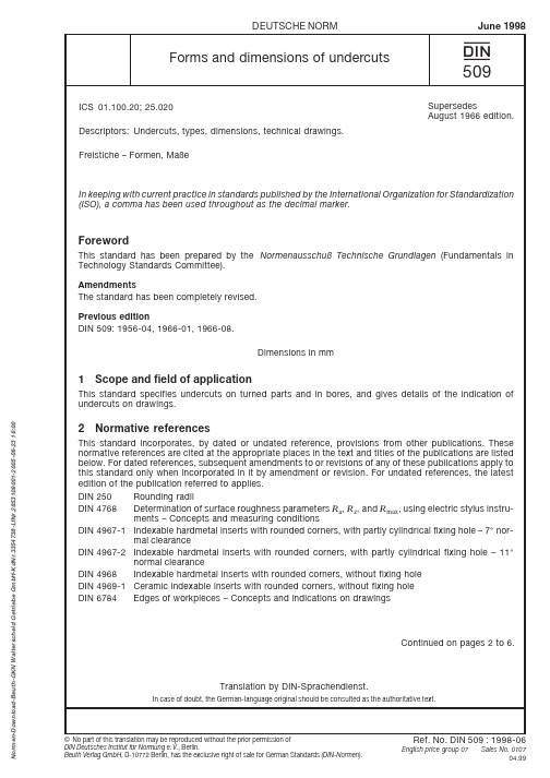
ICS 01.100.20; 25.020Descriptors:Undercuts, types, dimensions, technical drawings.Freistiche – Formen, MaßeDEUTSCHE NORM June 1998509{Continued on pages 2 to 6.Forms and dimensions of undercutsIn keeping with current practice in standards published by the International Organization for Standardization (ISO), a comma has been used throughout as the decimal marker.Translation by DIN-Sprachendienst.In case of doubt, the German-language original should be consulted as the authoritative text.SupersedesAugust 1966 edition.ForewordThis standard has been prepared by the Normenausschuß Technische Grundl agen (Fundamentals in Technology Standards Committee).AmendmentsThe standard has been completely revised.Previous editionDIN 509: 1956-04, 1966-01, 1966-08.Dimensions in mm1Scope and field of applicationThis standard specifies undercuts on turned parts and in bores, and gives details of the indication of undercuts on drawings.2Normative referencesThis standard incorporates, by dated or undated reference, provisions from other publications. These normative references are cited at the appropriate places in the text and titles of the publications are listed below. For dated references, subsequent amendments to or revisions of any of these publications apply to this standard only when incorporated in it by amendment or revision. For undated references, the latest edition of the publication referred to applies.DIN 250Rounding radii DIN 4768Determination of surface roughness parameters R a , R z , and R max , using electric stylus instru-ments – Concepts and measuring conditionsDIN 4967-1Indexable hardmetal inserts with rounded corners, with partly cylindrical fixing hole –7° nor-mal clearanceDIN 4967-2Indexable hardmetal inserts with rounded corners, with partly cylindrical fixing hole – 11°normal clearanceDIN 4968Indexable hardmetal inserts with rounded corners, without fixing hole DIN 4969-1Ceramic indexable inserts with rounded corners, without fixing hole DIN 6784Edges of workpieces – Concepts and indications on drawings-B e u t h -G K N W a l t e r s c h e i d G e t r i e b e G m b H -K d N r .3354738-L f N r .2853109001-2005-06-23 16:00Page 2DIN 509:1998-063ConceptsIn addition to the concepts relating to edges of workpieces (see DIN 6784), the following concept applies.UndercutInternal deviation from the ideal shape of a (rota-symmetrical) workpiece corner, either chamfered or rounded,of specified dimensions, producing a groove on the periphery or in a hole of a workpiece to provide clearance for subsequent machining (or assembly) operations.4Dimensions4.1Type E undercutType E undercuts are suitable if no great demands are placed on the shoulder in service and the cylindrical surface is intended for subsequent machining. They are also suitable for workpieces which will be matched with a component that has a relatively large counterbore or will not be in contact with the shoulder.z Machining allowance d 1Workpiece diameterFigure 1:Undercut for workpieces with a cylindrical surface intended for subsequent machining4.2Type FType F undercuts are to be used on workpieces with surfaces which are perpendicular to each other, intended for subsequent machining.z Machining allowance d 1Workpiece diameterFigure 2:Undercut for workpieces with shoulder and a cylindrical surface intendedfor subsequent machining-B e u t h -G K N W a l t e r s c h e i d G e t r i e b e G m b H -K d N r .3354738-L f N r .2853109001-2005-06-23 16:00Page 3DIN 509:1998-064.3Type GType G undercuts are to be used on workpieces not subjected to substantial fatigue stresses in service and thus require an undercut with a small included angle.z Machining allowance d 1Workpiece diameterFigure 3:Undercut with a smaller transition4.4Type HType H undercuts are to be used on workpieces similar to those specified for type F (but with a greater included angle).z Machining allowance d 1Workpiece diameterFigure 4:Undercut with a larger transition5Surface roughnessThe roughness of undercut surfaces shall be such that the arithmetical mean deviation of the profile, R a , is 3,2m m and the maximum two point height of the profile, R max *), is 25m m. Any other surface roughness param-eters shall be subject to agreement.6DesignationDesignation of a type E undercut, with a radius, r , of 0,8 mm and a depth, t 1, of 0,3 mm:Undercut DIN 509 – E 0,8 * 0,3Designation of a type E undercut, with a radius, r , of 0,8 mm, a depth, t 1, of 0,3 mm, and with R a = 1,6 m m and R max = 16 m m:Undercut DIN 509 – E 0,8 * 0,3 – R a 1,6 – R max 16-B e u t h -G K N W a l t e r s c h e i d G e t r i e b e G m b H -K d N r .3354738-L f N r .2853109001-2005-06-23 16:00Page 4DIN 509:1998-06Table 1:Undercut dimensionsTypeSeries 1Series 2Corresponding diameter d 12) forworkpiecessubjected to a normal stress concentration subjected to higher fatigue loads tandandandandOver 1,6 up to 3over 3 up to 18over 10 up to 18over 18 up to 80Over 18 up to 50over 18 up to 50over 18 up to 50over 50 up to 80over 80 up to 125over 125over 80over 801)Undercuts with series 1 radii as specified in DIN 250 are to be given preference. For types G and H, the radiiconform to those specified for indexable hardmetal inserts as in DIN 4967, DIN 4768 and DIN 4769-1.2) Components with a short shoulder and thin-walled components are excepted. When a workpiece has different diameters, it may be convenient for manufacturing reasons to use the same form and size of undercut at severalpoints.1)-B e u t h -G K N W a l t e r s c h e i d G e t r i e b e G m b H -K d N r .3354738-L f N r .2853109001-2005-06-23 16:00Page 5DIN 509:1998-068Counterbores on mating partFigure 6:Counterbores on mating part Table 3:Determination of dimension aTable 2:Machining allowanceType HMinimum size of a for typeUndercut size, r *t 1-B e u t h -G K N W a l t e r s c h e i d G e t r i e b e G m b H -K d N r .3354738-L f N r .2853109001-2005-06-23 16:00Page 6DIN 509:1998-069Indications on drawingsOn technical drawings, undercuts may either be shown in detail, giving all dimensions, or schematically, giving only the designation.EXAMPLE: Undercut F 1,2 * 0,2Undercut F 1,2 * 0,22Figure 7:Complete indication for F 1,2 * 0,2undercutFigure 8:Complete indication for E 1,2 * 0,2undercutDetail XFigure 9:Simplified indication for F 1,2 * 0,2undercut Figure 10:Simplified indication for E 1,2 * 0,2undercutDetailYExplanatory notesForms and dimensions of types G and H undercuts conform to those for indexable inserts as specified in DIN 4967-1 and DIN 4969-1 or as in DIN 4967, DIN 4968 or DIN 4969-1. For economic reasons, it is recom-mended that undercuts should be produced using these inserts.R aR a R maxR max-B e u t h -G K N W a l t e r s c h e i d G e t r i e b e G m b H -K d N r .3354738-L f N r .2853109001-2005-06-23 16:00。
din76-b标准退刀槽尺寸
摘要:
I.简介
- 介绍DIN 76-B标准
- 退刀槽的定义和作用
II.退刀槽尺寸
- 退刀槽的类型
- 退刀槽尺寸的计算方法
- 退刀槽尺寸的选择
III.应用领域
- 退刀槽在机械加工中的应用
- 退刀槽在模具制造中的应用
IV.结论
- 总结退刀槽在机械加工和模具制造中的重要性
- 强调正确选择退刀槽尺寸的重要性
正文:
DIN 76-B标准是德国工业标准,主要用于规范退刀槽的尺寸。
退刀槽是机械加工和模具制造中的一个重要概念,它是指在刀具加工过程中,为避免刀具与工件或夹具发生干涉而在刀具上设置的一种槽。
退刀槽的尺寸对于机械加工的效率和精度至关重要。
根据DIN 76-B标准,退刀槽分为两种类型:圆形退刀槽和方形退刀槽。
圆形退刀槽的尺寸计算公式为:退刀槽直径= 刀具直径+ 2 × 退刀距离。
方形退刀槽的尺寸计算公式为:退刀槽宽度= 刀具厚度+ 2 × 退刀距离。
退刀槽的深度一般为刀具厚度的1/3。
退刀槽尺寸的选择主要取决于刀具的类型、加工材料、加工工艺和机床性能。
选择合适的退刀槽尺寸可以提高刀具的使用寿命,降低刀具的磨损,提高机械加工的精度和效率。
退刀槽在机械加工和模具制造中有着广泛的应用。
在机械加工中,退刀槽可以避免刀具与工件或夹具发生干涉,从而提高刀具的使用寿命和加工精度。
在模具制造中,退刀槽可以提高模具的制造精度和使用寿命,降低模具的维修成本。
总之,DIN 76-B标准退刀槽尺寸对于机械加工和模具制造具有重要意义。
目前,数控铣床和镗铣加工中心使用最多的仍是7∶24工具锥柄。
但在高速加工机床上,1∶10空心短锥柄的使用正日益增多。
对于车削中心和车铣中心,则以1∶10短锥柄使用较多(车削中心使用的CZG圆柱柄工具系统不属本文讨论范围)。
自动换刀机床常用的7∶24工具锥柄标准主要有:中国国家标准GB 10944-89“自动换刀机床用7∶24圆锥工具柄部40、45和50号圆锥柄”;国际标准ISO 7388/1:1983(40、45和50号工具锥柄)和ISO 7388/3:1986(30号工具锥柄);德国标准分DIN 69871-1:1995(30、40、45、50和60号工具锥柄)和DIN 69871-2(40、45、50、55和60号工具锥柄)两种;日本现行标准为JIS B 6339:1998(30、35、40、45、50、55和60号工具锥柄),用于代替日本工作机械工业会标准MAS-403:1975(40、45、50和60号工具锥柄);美国现行标准为AMSE B5.50-1994(30、40、45、50和60号工具锥柄),用于代替ANSI/AMSE B5.50-1985标准。
手动换刀用7∶24工具锥柄的常见标准有国家标准GB 3837.3-83和国际标准ISO 297-82,以及机械行业标准JB 3381.1-83。
1∶10空心工具锥柄目前已有国家标准GB 19449.1-2004“带有法兰接触面的空心圆锥接口第1部分:柄部—尺寸”。
它等同采用了国际标准ISO 12164-1:2001的内容。
原德国标准DIN 69893-1:1996已被新的标准DIN 69873-1:2003代替,新的德国标准也等同采用了国际标准ISO 12164-1:2001的内容。
其它常见结构的1∶10工具锥柄基本采用企业标准,具有垄断性,如美国肯纳公司的KM型系列、瑞典山特维克公司的Capto系列、德国瓦尔特公司的NOVEX系列等。
自动换刀机床用7∶24工具锥柄的中国国家标准GB 10944-89是参照采用国际标准ISO 7388/1:1983制定的,除对极个别项目数据进行了圆整(如尾部螺纹底孔深度13)或未规定数据(如法兰上的键槽根底倒角)外,其它数据完全相同。
ICS 01.100.20; 25.020Descriptors:Undercuts, types, dimensions, technical drawings.Freistiche – Formen, MaßeDEUTSCHE NORM June 1998509{Continued on pages 2 to 6.Forms and dimensions of undercutsIn keeping with current practice in standards published by the International Organization for Standardization (ISO), a comma has been used throughout as the decimal marker.Translation by DIN-Sprachendienst.In case of doubt, the German-language original should be consulted as the authoritative text.SupersedesAugust 1966 edition.ForewordThis standard has been prepared by the Normenausschuß Technische Grundl agen (Fundamentals in Technology Standards Committee).AmendmentsThe standard has been completely revised.Previous editionDIN 509: 1956-04, 1966-01, 1966-08.Dimensions in mm1Scope and field of applicationThis standard specifies undercuts on turned parts and in bores, and gives details of the indication of undercuts on drawings.2Normative referencesThis standard incorporates, by dated or undated reference, provisions from other publications. These normative references are cited at the appropriate places in the text and titles of the publications are listed below. For dated references, subsequent amendments to or revisions of any of these publications apply to this standard only when incorporated in it by amendment or revision. For undated references, the latest edition of the publication referred to applies.DIN 250Rounding radii DIN 4768Determination of surface roughness parameters R a , R z , and R max , using electric stylus instru-ments – Concepts and measuring conditionsDIN 4967-1Indexable hardmetal inserts with rounded corners, with partly cylindrical fixing hole –7° nor-mal clearanceDIN 4967-2Indexable hardmetal inserts with rounded corners, with partly cylindrical fixing hole – 11°normal clearanceDIN 4968Indexable hardmetal inserts with rounded corners, without fixing hole DIN 4969-1Ceramic indexable inserts with rounded corners, without fixing hole DIN 6784Edges of workpieces – Concepts and indications on drawings-B e u t h -G K N W a l t e r s c h e i d G e t r i e b e G m b H -K d N r .3354738-L f N r .2853109001-2005-06-23 16:00Page 2DIN 509:1998-063ConceptsIn addition to the concepts relating to edges of workpieces (see DIN 6784), the following concept applies.UndercutInternal deviation from the ideal shape of a (rota-symmetrical) workpiece corner, either chamfered or rounded,of specified dimensions, producing a groove on the periphery or in a hole of a workpiece to provide clearance for subsequent machining (or assembly) operations.4Dimensions4.1Type E undercutType E undercuts are suitable if no great demands are placed on the shoulder in service and the cylindrical surface is intended for subsequent machining. They are also suitable for workpieces which will be matched with a component that has a relatively large counterbore or will not be in contact with the shoulder.z Machining allowance d 1Workpiece diameterFigure 1:Undercut for workpieces with a cylindrical surface intended for subsequent machining4.2Type FType F undercuts are to be used on workpieces with surfaces which are perpendicular to each other, intended for subsequent machining.z Machining allowance d 1Workpiece diameterFigure 2:Undercut for workpieces with shoulder and a cylindrical surface intendedfor subsequent machining-B e u t h -G K N W a l t e r s c h e i d G e t r i e b e G m b H -K d N r .3354738-L f N r .2853109001-2005-06-23 16:00Page 3DIN 509:1998-064.3Type GType G undercuts are to be used on workpieces not subjected to substantial fatigue stresses in service and thus require an undercut with a small included angle.z Machining allowance d 1Workpiece diameterFigure 3:Undercut with a smaller transition4.4Type HType H undercuts are to be used on workpieces similar to those specified for type F (but with a greater included angle).z Machining allowance d 1Workpiece diameterFigure 4:Undercut with a larger transition5Surface roughnessThe roughness of undercut surfaces shall be such that the arithmetical mean deviation of the profile, R a , is 3,2m m and the maximum two point height of the profile, R max *), is 25m m. Any other surface roughness param-eters shall be subject to agreement.6DesignationDesignation of a type E undercut, with a radius, r , of 0,8 mm and a depth, t 1, of 0,3 mm:Undercut DIN 509 – E 0,8 * 0,3Designation of a type E undercut, with a radius, r , of 0,8 mm, a depth, t 1, of 0,3 mm, and with R a = 1,6 m m and R max = 16 m m:Undercut DIN 509 – E 0,8 * 0,3 – R a 1,6 – R max 16-B e u t h -G K N W a l t e r s c h e i d G e t r i e b e G m b H -K d N r .3354738-L f N r .2853109001-2005-06-23 16:00Page 4DIN 509:1998-06Table 1:Undercut dimensionsTypeSeries 1Series 2Corresponding diameter d 12) forworkpiecessubjected to a normal stress concentration subjected to higher fatigue loads tandandandandOver 1,6 up to 3over 3 up to 18over 10 up to 18over 18 up to 80Over 18 up to 50over 18 up to 50over 18 up to 50over 50 up to 80over 80 up to 125over 125over 80over 801)Undercuts with series 1 radii as specified in DIN 250 are to be given preference. For types G and H, the radiiconform to those specified for indexable hardmetal inserts as in DIN 4967, DIN 4768 and DIN 4769-1.2) Components with a short shoulder and thin-walled components are excepted. When a workpiece has different diameters, it may be convenient for manufacturing reasons to use the same form and size of undercut at severalpoints.1)-B e u t h -G K N W a l t e r s c h e i d G e t r i e b e G m b H -K d N r .3354738-L f N r .2853109001-2005-06-23 16:00Page 5DIN 509:1998-068Counterbores on mating partFigure 6:Counterbores on mating part Table 3:Determination of dimension aTable 2:Machining allowanceType HMinimum size of a for typeUndercut size, r *t 1-B e u t h -G K N W a l t e r s c h e i d G e t r i e b e G m b H -K d N r .3354738-L f N r .2853109001-2005-06-23 16:00Page 6DIN 509:1998-069Indications on drawingsOn technical drawings, undercuts may either be shown in detail, giving all dimensions, or schematically, giving only the designation.EXAMPLE: Undercut F 1,2 * 0,2Undercut F 1,2 * 0,22Figure 7:Complete indication for F 1,2 * 0,2undercutFigure 8:Complete indication for E 1,2 * 0,2undercutDetail XFigure 9:Simplified indication for F 1,2 * 0,2undercut Figure 10:Simplified indication for E 1,2 * 0,2undercutDetailYExplanatory notesForms and dimensions of types G and H undercuts conform to those for indexable inserts as specified in DIN 4967-1 and DIN 4969-1 or as in DIN 4967, DIN 4968 or DIN 4969-1. For economic reasons, it is recom-mended that undercuts should be produced using these inserts.R aR a R maxR max-B e u t h -G K N W a l t e r s c h e i d G e t r i e b e G m b H -K d N r .3354738-L f N r .2853109001-2005-06-23 16:00。