一款多功能电能计量芯片简介CS5463
- 格式:pptx
- 大小:5.40 MB
- 文档页数:30
带有串行接口的功率/电能计量芯片CS5460及其应用摘要:CS5460是CRYSTAL公司最新推出的带有串行接口的单相双向功率/电能计量集成电路芯片,该芯片比目前比较流行的电子电度表芯片如AD7750、AD7755更容易实现与微处理器的连接。
用CS5460可以方便的组成多功能电子式电度表和分布电度表和分布式电能计量管理系统。
本文详细地介绍了CS5460的功能和使用方法。
关键词:CS5460;串行接口;功率/电能;计量;应用1.概述CS5460是CRYSTAL公司最新推出的带有串行接口的单相双向功率/电能计量集成电路芯片。
与目前在电子式电度表应用中广泛使用的AD7750和AD7755(见《国外电子元器件》1999年第3期文章)相比较,CS5460增加了以下功能:·具有片内看门狗定时器(Watch Dog Timer)与内部电源监视器;·具有瞬时电流、瞬时电压、瞬时功率、电流有效值、电压有效值、功率有效值测量及电能计量功能;·提供了外部复位引脚;·双向串行接口与内部寄存器阵列可以方便地与微处理器相连接;·外部时钟最高频率可达20MHz;·具有功率方向输出指示。
这些增加的功能更加便于与微处理器(MPU)接口,并能方便地实现电压、电流、功率的测量和用电量累积等功能。
2. 基本结构与技术指标2.1内部结构CS5460内部集成了两个△-∑A/D转换器、高、低通数字滤波器、能量计算单元、串行接口、数字-频率转换器、寄存器阵列和看门狗定时器等模拟、数字信号处理单元,其内部结构框图如图1所示。
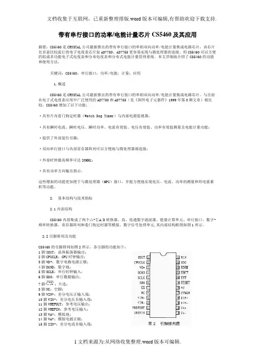
2.2引脚排列及功能CS5460的引脚排列如图2所示。
各引脚的功能如下:1脚XOUT:晶体振荡器输出;2脚CPUCLK:CPU时钟输出;3脚VD+:数字电路电源正极;4脚DGND:数字地;5脚SCLK:串行时钟输入;6脚SDO:串行数据输出;7脚:片选;8脚NC:空脚;9脚VIN+:差分电压正输入端;10脚VIN-:差分电压负输入端;11脚VREFOUT:参考电压输出;12脚VREFIN:参考电压输入;13脚VA-:模拟地;14脚VA+:模拟电源正极;15脚IIN-:差分电流负输入端;16脚IIN+:差分电流正输入端;17脚PFMON:电源掉电监视输出;18脚NC:空脚;19脚:复位输入;20脚:中断输出;21脚:电能脉冲输出;22脚:功率方向指示输出;脚SDI:串行数据输入;24脚XIN:晶体振荡器输入。
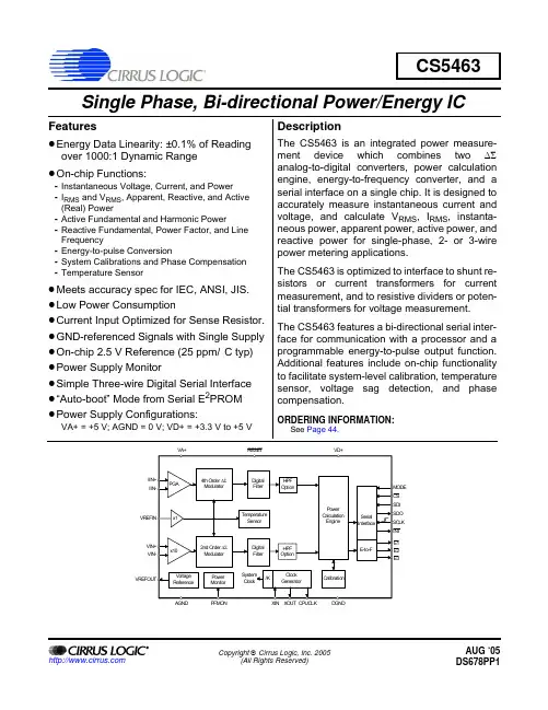
Copyright © Cirrus Logic, Inc. 2005(All Rights Reserved)CS5463Single Phase, Bi-directional Power/Energy ICFeaturesz Energy Data Linearity: ±0.1% of Readingover 1000:1 Dynamic Rangez On-chip Functions:-Instantaneous Voltage, Current, and Power-I RMS and V RMS , Apparent, Reactive, and Active (Real) Power-Active Fundamental and Harmonic Power-Reactive Fundamental, Power Factor, and Line Frequency-Energy-to-pulse Conversion-System Calibrations and Phase Compensation -Temperature Sensorz Meets accuracy spec for IEC, ANSI, JIS.z Low Power Consumptionz Current Input Optimized for Sense Resistor.z GND-referenced Signals with Single Supply z On-chip 2.5V Reference (25 ppm/°C typ)z Power Supply Monitorz Simple Three-wire Digital Serial Interface z “Auto-boot” Mode from Serial E 2PROM z Power Supply Configurations:VA+ = +5V; AGND = 0V; VD+ = +3.3V to +5VDescriptionThe CS5463 is an integrated power measure-ment device which combines two ∆Σanalog-to-digital converters, power calculation engine, energy-to-frequency converter, and a serial interface on a single chip. It is designed to accurately measure instantaneous current and voltage, and calculate V RMS , I RMS , instanta-neous power, apparent power, active power, and reactive power for single-phase, 2- or 3-wire power metering applications.The CS5463 is optimized to interface to shunt re-sistors or current transformers for current measurement, and to resistive dividers or poten-tial transformers for voltage measurement. The CS5463 features a bi-directional serial inter-face for communication with a processor and a programmable energy-to-pulse output function.Additional features include on-chip functionality to facilitate system-level calibration, temperature sensor, voltage sag detection, and phase compensation.ORDERING INFORMATION:See Page 44.AUG ‘05TABLE OF CONTENTS1. Overview . . . . . . . . . . . . . . . . . . . . . . . . . . . . . . . . . . . . . . . . . . . . . . . . . . . . . . . . . . 52. Pin Description . . . . . . . . . . . . . . . . . . . . . . . . . . . . . . . . . . . . . . . . . . . . . . . . . . . . . 63. Characteristics & Specifications . . . . . . . . . . . . . . . . . . . . . . . . . . . . . . . . . . . . . . . 74. Theory of Operation . . . . . . . . . . . . . . . . . . . . . . . . . . . . . . . . . . . . . . . . . . . . . . . . 144.1 Digital Filters . . . . . . . . . . . . . . . . . . . . . . . . . . . . . . . . . . . . . . . . . . . . . . . . . . . . . . 144.2 Voltage and Current Measurements . . . . . . . . . . . . . . . . . . . . . . . . . . . . . . . . . . . . 144.3 Power Measurements . . . . . . . . . . . . . . . . . . . . . . . . . . . . . . . . . . . . . . . . . . . . . . . 144.4 Linearity Performance . . . . . . . . . . . . . . . . . . . . . . . . . . . . . . . . . . . . . . . . . . . . . . . 155. Functional Description . . . . . . . . . . . . . . . . . . . . . . . . . . . . . . . . . . . . . . . . . . . . . . 165.1 Analog Inputs . . . . . . . . . . . . . . . . . . . . . . . . . . . . . . . . . . . . . . . . . . . . . . . . . . . . . 165.1.1 Voltage Channel . . . . . . . . . . . . . . . . . . . . . . . . . . . . . . . . . . . . . . 165.1.2 Current Channel . . . . . . . . . . . . . . . . . . . . . . . . . . . . . . . . . . . . . . . 165.2 IIR Filters . . . . . . . . . . . . . . . . . . . . . . . . . . . . . . . . . . . . . . . . . . . . . . . . . . . . . . . . . 165.3 High-pass Filters . . . . . . . . . . . . . . . . . . . . . . . . . . . . . . . . . . . . . . . . . . . . . . . . . . . 165.4 Performing Measurements . . . . . . . . . . . . . . . . . . . . . . . . . . . . . . . . . . . . . . . . . . . 165.5 Energy Pulse Output . . . . . . . . . . . . . . . . . . . . . . . . . . . . . . . . . . . . . . . . . . . . . . . . 175.5.1 Active Energy . . . . . . . . . . . . . . . . . . . . . . . . . . . . . . . . . . . . . . . . . 175.5.2 Apparent Energy Mode . . . . . . . . . . . . . . . . . . . . . . . . . . . . . . . . . 185.5.3 Reactive Energy Mode . . . . . . . . . . . . . . . . . . . . . . . . . . . . . . . . . . 185.5.4 Voltage Channel Sign Mode . . . . . . . . . . . . . . . . . . . . . . . . . . . . . 185.5.5 PFMON Output Mode . . . . . . . . . . . . . . . . . . . . . . . . . . . . . . . . . . 195.5.6 Design Example . . . . . . . . . . . . . . . . . . . . . . . . . . . . . . . . . . . . . . . 195.6 Sag and Fault Detect Feature . . . . . . . . . . . . . . . . . . . . . . . . . . . . . . . . . . . . . . . . . 195.7 On-chip Temperature Sensor . . . . . . . . . . . . . . . . . . . . . . . . . . . . . . . . . . . . . . . . . 195.8 Voltage Reference . . . . . . . . . . . . . . . . . . . . . . . . . . . . . . . . . . . . . . . . . . . . . . . . . 205.9 System Initialization . . . . . . . . . . . . . . . . . . . . . . . . . . . . . . . . . . . . . . . . . . . . . . . . 205.10 Power-down States . . . . . . . . . . . . . . . . . . . . . . . . . . . . . . . . . . . . . . . . . . . . . . . . 205.11 Oscillator Characteristics . . . . . . . . . . . . . . . . . . . . . . . . . . . . . . . . . . . . . . . . . . . 205.12 Event Handler . . . . . . . . . . . . . . . . . . . . . . . . . . . . . . . . . . . . . . . . . . . . . . . . . . . . 215.12.1 Typical Interrupt Handler . . . . . . . . . . . . . . . . . . . . . . . . . . . . . . . 215.13 Serial Port Overview . . . . . . . . . . . . . . . . . . . . . . . . . . . . . . . . . . . . . . . . . . . . . . . 215.13.1 Serial Port Interface . . . . . . . . . . . . . . . . . . . . . . . . . . . . . . . . . . . 215.14 Register Paging . . . . . . . . . . . . . . . . . . . . . . . . . . . . . . . . . . . . . . . . . . . . . . . . . . . 225.15 Commands . . . . . . . . . . . . . . . . . . . . . . . . . . . . . . . . . . . . . . . . . . . . . . . . . . . . . . 235.15.1 Start Conversions . . . . . . . . . . . . . . . . . . . . . . . . . . . . . . . . . . . . . . . . . . 235.15.2 SYNC0 and SYNC1 . . . . . . . . . . . . . . . . . . . . . . . . . . . . . . . . . . . . . . . . 235.15.3 Power-up/Halt . . . . . . . . . . . . . . . . . . . . . . . . . . . . . . . . . . . . . . . . . . . . 235.15.4 Power-down and Software Reset . . . . . . . . . . . . . . . . . . . . . . . . . . . . . . 235.15.5 Register Read/Write . . . . . . . . . . . . . . . . . . . . . . . . . . . . . . . . . . . . . . . 245.15.6 Calibration . . . . . . . . . . . . . . . . . . . . . . . . . . . . . . . . . . . . . . . . . . . . . . . 256. Register Description . . . . . . . . . . . . . . . . . . . . . . . . . . . . . . . . . . . . . . . . . . . . . . . 266.1 Page 0 Registers . . . . . . . . . . . . . . . . . . . . . . . . . . . . . . . . . . . . . . . . . . . . . . . . . . . 266.1.1 Configuration Register ( Config ). . . . . . . . . . . . . . . . . . . . . . . . . . . . . . . . 266.1.2 Current and Voltage DC Offset Register ( I DCoff , V DCoff ) . . . . . . . . . . . . 276.1.3 Current and Voltage Gain Register ( I gn , V gn ) . . . . . . . . . . . . . . . . . . . . 276.1.4 Cycle Count Register ( Cycle Count ) . . . . . . . . . . . . . . . . . . . . . . . . . . . . 276.1.5 PulseRateE Register ( PulseRateE ). . . . . . . . . . . . . . . . . . . . . . . . . . . . . 276.1.6 Instantaneous Current, Voltage, and Power Registers ( I , V , P ) . . . . . . 286.1.7 Active (Real) Power Register ( P Active ) . . . . . . . . . . . . . . . . . . . . . . . . . . 286.1.8 RMS Current & Voltage Registers ( I RMS , V RMS ). . . . . . . . . . . . . . . . . . 286.1.9 Epsilon Register ( ε ). . . . . . . . . . . . . . . . . . . . . . . . . . . . . . . . . . . . . . . . . 286.1.10 Power Offset Register ( P off ). . . . . . . . . . . . . . . . . . . . . . . . . . . . . . . . . 296.1.11 Status Register and Mask Register ( Status , Mask ). . . . . . . . . . . . . . . 296.1.12 Current and Voltage AC Offset Register ( V ACoff , I ACoff ). . . . . . . . . . . 306.1.13 Operational Mode Register ( Mode ). . . . . . . . . . . . . . . . . . . . . . . . . . . . 306.1.14 Temperature Register ( T ) . . . . . . . . . . . . . . . . . . . . . . . . . . . . . . . . . . . 316.1.15 Average and Instantaneous Reactive Power Register ( Q AVG , Q ) . . . . 316.1.16 Peak Current and Peak Voltage Register ( I peak , V peak ). . . . . . . . . . . . 316.1.17 Reactive Power Register ( Q Trig ). . . . . . . . . . . . . . . . . . . . . . . . . . . . . . 326.1.18 Power Factor Register ( PF ) . . . . . . . . . . . . . . . . . . . . . . . . . . . . . . . . . 326.1.19 Apparent Power Register ( S ) . . . . . . . . . . . . . . . . . . . . . . . . . . . . . . . . 326.1.20 Control Register ( Ctrl ). . . . . . . . . . . . . . . . . . . . . . . . . . . . . . . . . . . . . . 336.1.21 Harmonic Active Power Register ( P H ) . . . . . . . . . . . . . . . . . . . . . . . . . 336.1.22 Fundamental Active Power Register ( P F ) . . . . . . . . . . . . . . . . . . . . . . 336.1.23 Fundamental Reactive Power Register ( Q H ) . . . . . . . . . . . . . . . . . . . . 346.1.24 Page Register. . . . . . . . . . . . . . . . . . . . . . . . . . . . . . . . . . . . . . . . . . . . . 346.2 Page 1 Registers . . . . . . . . . . . . . . . . . . . . . . . . . . . . . . . . . . . . . . . . . . . . . . . . . . 346.2.1 Temperature Gain Register ( T Gain ). . . . . . . . . . . . . . . . . . . . . . . . . . . . . 346.2.2 Temperature Offset Register ( T Off ). . . . . . . . . . . . . . . . . . . . . . . . . . . . . 346.3 Page 3 Registers . . . . . . . . . . . . . . . . . . . . . . . . . . . . . . . . . . . . . . . . . . . . . . . . . . 356.3.1 Voltage Sag and Current Fault Duration Registers( VSAG Duration , ISAG Duration ) . . . . . . . . . . . . . . . . . . . . . . . . . . . . . . . . . 356.3.2 Voltage Sag and Current Fault Level Registers( VSAG Level , ISAG Level ) . . . . . . . . . . . . . . . . . . . . . . . . . . . . . . . . . . . . . 35 7. System Calibration . . . . . . . . . . . . . . . . . . . . . . . . . . . . . . . . . . . . . . . . . . . . . . . . . 367.1 Channel Offset and Gain Calibration . . . . . . . . . . . . . . . . . . . . . . . . . . . . . . . . . . . 367.1.1 Calibration Sequence . . . . . . . . . . . . . . . . . . . . . . . . . . . . . . . . . . 367.1.1.1 Duration of Calibration Sequence . . . . . . . . . . . . . . . . . . . . . 367.1.2 Offset Calibration Sequence . . . . . . . . . . . . . . . . . . . . . . . . . . . . . 367.1.2.1 DC Offset Calibration Sequence . . . . . . . . . . . . . . . . . . . . . . 367.1.2.2 AC Offset Calibration Sequence . . . . . . . . . . . . . . . . . . . . . . 377.1.3 Gain Calibration Sequence . . . . . . . . . . . . . . . . . . . . . . . . . . . . . . 377.1.3.1 AC Gain Calibration Sequence . . . . . . . . . . . . . . . . . . . . . . . 377.1.3.2 DC Gain Calibration Sequence . . . . . . . . . . . . . . . . . . . . . . . 387.1.4 Order of Calibration Sequences . . . . . . . . . . . . . . . . . . . . . . . . . . 387.2 Phase Compensation . . . . . . . . . . . . . . . . . . . . . . . . . . . . . . . . . . . . . . . . . . . . . . . 387.3 Active Power Offset . . . . . . . . . . . . . . . . . . . . . . . . . . . . . . . . . . . . . . . . . . . . . . . . 388. Auto-boot Mode Using E2PROM . . . . . . . . . . . . . . . . . . . . . . . . . . . . . . . . . . . . . . 398.1 Auto-boot Configuration . . . . . . . . . . . . . . . . . . . . . . . . . . . . . . . . . . . . . . . . . . . . . 398.2 Auto-boot Data for E2PROM . . . . . . . . . . . . . . . . . . . . . . . . . . . . . . . . . . . . . . . . . . 398.3 Which E2PROMs Can Be Used? . . . . . . . . . . . . . . . . . . . . . . . . . . . . . . . . . . . . . . 399. Basic Application Circuits . . . . . . . . . . . . . . . . . . . . . . . . . . . . . . . . . . . . . . . . . . . 4010. Package Dimensions . . . . . . . . . . . . . . . . . . . . . . . . . . . . . . . . . . . . . . . . . . . . . . 4311. Ordering Information . . . . . . . . . . . . . . . . . . . . . . . . . . . . . . . . . . . . . . . . . . . . . 4412. Environmental, Manufacturing, & Handling Information . . . . . . . . . . . . . . . . . 4413. Revision History . . . . . . . . . . . . . . . . . . . . . . . . . . . . . . . . . . . . . . . . . . . . . . . . . 44LIST OF FIGURESFigure 1. CS5463 Read and Write Timing Diagrams (12)Figure 2. Timing Diagram for E1, E2 and E3 (13)Figure 3. Data Measurement Flow Diagram (14)Figure 4. Power Calculation Flow (15)Figure 5. Active and Reactive energy pulse outputs (17)Figure 6. Apparent energy pulse outputs (18)Figure 7. Voltage Channel Sign Pulse outputs (18)Figure 8. PFMON output to pin E3 (19)Figure 9. Sag and Fault Detect (19)Figure 10. Oscillator Connection (20)Figure 11. CS5463 Memory Map (22)Figure 12. Calibration Data Flow (36)Figure 13. System Calibration of Offset (36)Figure 14. System Calibration of Gain (37)Figure 15. Example of AC Gain Calibration (37)Figure 16. Example of AC Gain Calibration (37)Figure 17. Typical Interface of E2PROM to CS5463 (39)Figure 18. Typical Connection Diagram (Single-phase, 2-wire – Direct Connect to Power Line)40 Figure 20. Typical Connection Diagram (Single-phase, 3-wire) (41)Figure 19. Typical Connection Diagram (Single-phase, 2-wire – Isolated from Power Line) (41)Figure 21. Typical Connection Diagram (Single-phase, 3-wire – No Neutral Available) (42)LIST OF TABLESTable 1. Current Channel PGA Setting . . . . . . . . . . . . . . . . . . . . . . . . . . . . . . . . . . . . . . . . . . . 16 Table 2. E2 Pin Configuration . . . . . . . . . . . . . . . . . . . . . . . . . . . . . . . . . . . . . . . . . . . . . . . . . . 1717 Table 4. Interrupt Configuration . . . . . . . . . . . . . . . . . . . . . . . . . . . . . . . . . . . . . . . . . . . . . . . . 211.OVERVIEWThe CS5463 is a CMOS monolithic power measurement device with a computation engine and an ener-gy-to-frequency pulse output. The CS5463 combines a programmable gain amplifier, two ∆Σ Ana-log-to-Digital Converters (ADCs), system calibration and a computation engine on a single chip.The CS5463 is designed for power measurement applications and is optimized to interface to a current sense resistor or transformer for current measurement, and to a resistive divider or potential transformer for voltage measurement. The current channel provides programmable gains to accommodate various in-put levels from a multitude of sensing elements. With single +5V supply on VA+/AGND, both of the CS5463’s input channels can accommodate common mode plus signal levels between (AGND - 0.25V) and VA+.The CS5463 also is equipped with a computation engine that calculates instantaneous power, I RMS, V RMS, apparent power, active (real) power, reactive power, harmonic active power, active and reactive fundamental power, and power factor. The CS5463 additional features include line frequency, current and voltage sag detection, zero-cross detection, positive-only accumulation mode, and three programmable pulse output pins. To facilitate communication to a microprocessor, the CS5463 includes a simple three-wire serial interface which is SPI™ and Microwire™ compatible. The CS5463 provides three out-puts for energy registration. E1, E2 and E3 are designed to interface to a microprocessor.2. PIN DESCRIPTION Clock GeneratorCrystal Out Crystal In 1,24XOUT, XIN - The output and input of an inverting amplifier. Oscillation occurs when connected toa crystal, providing an on-chip system clock. Alternatively, an external clock can be supplied tothe XIN pin to provide the system clock for the device.CPU Clock Output2CPUCLK - Output of on-chip oscillator which can drive one standard CMOS load.Control Pins and Serial Data I/OSerial Clock Input5SCLK - A Schmitt-Trigger input pin. Clocks data from the SDI pin into the receive buffer and outof the transmit buffer onto the SDO pin when CS is low.Serial Data Output6SDO -Serial port data output pin.SDO is forced into a high-impedance state when CS is high. Chip Select7CS - Low, activates the serial port interface.Mode Select8MODE - High, enables the “auto-boot” mode. The mode pin has an internal pull-down resistor. Energy Output18,21,22E3,E1, E2 - Active-low pulses with an output frequency proportional to the selected power. Con-figurable outputs for active, apparent, and reactive power, negative energy indication, zero crossdetection, and power failure monitoring. E1, E2, E3 outputs are configured in the OperationalModes Register.Reset19RESET - A Schmitt-Trigger input pin. Low activates Reset, all internal registers (some of whichdrive output pins) are set to their default states.Interrupt20INT - Low, indicates that an enabled event has occurred.Serial Data Input23SDI - Serial port data input pin. Data will be input at a rate determined by SCLK.Analog Inputs/OutputsDifferential Voltage Inputs9,10VIN+, VIN- - Differential analog input pins for the voltage channel.Differential Current Inputs15,16IIN+, IIN- - Differential analog input pins for the current channel.Voltage Reference Output11VREFOUT - The on-chip voltage reference output. The voltage reference has a nominal magni-tude of 2.5V and is referenced to the AGND pin on the converter.Voltage Reference Input12VREFIN - The input to this pin establishes the voltage reference for the on-chip modulator. Power Supply ConnectionsPositive Digital Supply3VD+ - The positive digital supply.Digital Ground4DGND - Digital Ground.Positive Analog Supply14VA+ - The positive analog supply.Analog Ground13AGND - Analog ground.Power Fail Monitor 17PFMON - The power fail monitor pin monitors the analog supply. If the analog supply does notmeet or falls below PFMON’s voltage threshold, a Low-supply Detect (LSD) event is set in thestatus register.3.CHARACTERISTICS & SPECIFICATIONSRECOMMENDED OPERATING CONDITIONSANALOG CHARACTERISTICS•Min / Max characteristics and specifications are guaranteed over all Operating Conditions.•Typical characteristics and specifications are measured at nominal supply voltages and TA = 25°C.•VA+ = VD+ = 5V ±5%; AGND = DGND = 0V; VREFIN = +2.5V. All voltages with respect to 0V.•MCLK = 4.096MHz.Notes: 1.Applies when the HPF option is enabled.2.Applies when the line frequency is equal to the product of the Output Word Rate (OWR) and the valueof epsilon (ε).ParameterSymbol Min Typ MaxUnit Positive Digital Power Supply VD+ 3.135 5.0 5.25V Positive Analog Power Supply VA+ 4.75 5.0 5.25V Voltage ReferenceVREFIN - 2.5-V Specified Temperature RangeT A -40-+85°CParameterSymbol Min Typ Max UnitAccuracyActive Power All Gain Ranges(Note 1)Input Range 0.1% - 100%P Active -±0.1-%Average Reactive Power All Gain Ranges(Note 1 and 2)Input Range 0.1% - 100%Q Avg -±0.2-%Power Factor All Gain Ranges(Note 1 and 2)Input Range 1.0% - 100%Input Range 0.1% - 1.0%PF--±0.2±0.27--%%Current RMS All Gain Ranges(Note 1)Input Range 1.0% - 100%Input Range 0.1% - 1.0%I RMS--±0.1±0.17--%%%Voltage RMS All Gain Ranges(Note 1)Input Range 5% - 100%V RMS-±0.1-%Analog Inputs (Both Channels)Common Mode Rejection (DC,50,60Hz)CMRR80--dB Common Mode + SignalAll Gain Ranges-0.25-VA+V Analog Inputs (Current Channel)Differential Input Range (Gain = 10)[(IIN+) - (IIN-)](Gain = 50)IIN --500100--mV P-P mV P-P Total Harmonic Distortion(Gain = 50)THD 8094-dB Crosstalk with Voltage Channel at Full Scale (50, 60Hz)--115-dB Input Capacitance (Gain = 10)(Gain = 50)IC --3252--pF pF Effective Input Impedance EII 30--k ΩNoise (Referred to Input)(Gain = 10)(Gain = 50)N I ----22.54.5µV rms µV rms Offset Drift (Without the High Pass Filter)OD - 4.0-µV/°C Gain Error(Note 3)GE-±0.4%ANALOG CHARACTERISTICS (Continued)Notes: 3.Applies before system calibration.4.All outputs unloaded. All inputs CMOS level.5.Definition for PSRR: VREFIN tied to VREFOUT, VA+ = VD+ = 5V, a 150mV (zero-to-peak) (60Hz)sinewave is imposed onto the +5V DC supply voltage at VA+ and VD+ pins. The “+” and “-” input pins of both input channels are shorted to AGND. Then the CS5463 is commanded to continuous conversion acquisition mode, and digital output data is collected for the channel under test. The (zero-to-peak) value of the digital sinusoidal output signal is determined, and this value is converted into the(zero-to-peak) value of the sinusoidal voltage (measured in mV) that would need to be applied at the channel’s inputs, in order to cause the same digital sinusoidal output. This voltage is then defined as Veq. PSRR is then (in dB):6.When voltage level on PFMON is sagging, and LSD bit is at 0, the voltage at which LSD bit is set to 1.7.If the LSD bit has been set to 1 (because PFMON voltage fell below PMLO), this is the voltage level onPFMON at which the LSD bit can be permanently reset back to 0.ParameterSymbol MinTyp Max Unit Analog Inputs (Voltage Channel)Differential Input Range [(VIN+) - (VIN-)]VIN - 500-mV P-P Total Harmonic DistortionTHD 6575-dB Crosstalk with Current Channel at Full Scale (50, 60Hz)--70-dB Input Capacitance All Gain Ranges IC -0.2-pF Effective Input Impedance EII 2--M ΩNoise (Referred to Input)N V --140µV rms Offset Drift (Without the High Pass Filter)OD -16.0-µV/°C Gain Error(Note 3)GE -±3.0%Temperature ChannelTemperature AccuracyT -±5-°C Power SuppliesPower Supply Currents (Active State)I A+I D+ (VA+ = VD+ = 5V)I D+ (VA+ = 5V, VD+ = 3.3V)PSCA PSCD PSCD --- 1.32.91.7---mA mA mA Power Consumption Active State (VA+ = VD+ = 5V)(Note 4) Active State (VA+ = 5V, VD+ = 3.3V)Stand-by State Sleep StatePC----2111.68102917.5--mW mW mW µW Power Supply Rejection Ratio (50, 60Hz)(Note 5)Voltage ChannelCurrent ChannelPSRR 4570-6575---dB dB PFMON Low-voltage Trigger Threshold (Note 6)PMLO2.3 2.45-V PFMON High-voltage Power-on Trip Point (Note 7)PMHI- 2.552.7VPSRR 20150V eq---------log ⋅=VOLTAGE REFERENCENotes:8.The voltage at VREFOUT is measured across the temperature range. From these measurements the9.Specified at maximum recommended output of 1µA, source or sink.DIGITAL CHARACTERISTICS•Min / Max characteristics and specifications are guaranteed over all Operating Conditions.•Typical characteristics and specifications are measured at nominal supply voltages and TA = 25°C.•VA+ = VD+ = 5V ±5%; AGND = DGND = 0V. All voltages with respect to 0V.•MCLK = 4.096MHz.ParameterSymbol Min Typ Max Unit Reference OutputOutput VoltageVREFOUT+2.4+2.5+2.6V Temperature Coefficient (Note 8)TC VREF -2560ppm/°C Load Regulation(Note 9)∆V R -610mV Reference InputInput Voltage Range VREFIN+2.4+2.5+2.6V Input Capacitance -4-pF Input CVF Current-25-nAParameterSymbol MinTypMax Unit Master Clock CharacteristicsMaster Clock Frequency Internal Gate Oscillator (Note 11)MCLK 2.5 4.09620MHz Master Clock Duty Cycle 40-60%CPUCLK Duty Cycle(Note 12 and 13)40-60%Filter CharacteristicsPhase Compensation Range (Voltage Channel, 60Hz)-2.8-+2.8°Input Sampling RateDCLK = MCLK/K -DCLK/8-Hz Digital Filter Output Word Rate (Both Channels)OWR-DCLK/1024-Hz High-pass Filter Corner Frequency-3dB -0.5-Hz Full-scale DC Calibration Range (Referred to Input )(Note 14)FSCR 25-100%F.S.Channel-to-channel Time-shift Error(Note 15)1.0µsInput/Output CharacteristicsHigh-level Input VoltageAll Pins Except XIN and SCLK and RESETXINSCLK and RESET V IH0.6 VD+(VD+) - 0.50.8 VD+------V V V Low-level Input Voltage (VD =5V)All Pins Except XIN and SCLK and RESETXINSCLK and RESETV IL------0.81.50.2 VD+V V VNotes:10.All measurements performed under static conditions.11. If a crystal is used, then XIN frequency must remain between 2.5MHz -5.0MHz. If an externaloscillator is used, XIN frequency range is 2.5MHz -20MHz, but K must be set so that MCLK is between 2.5MHz -5.0MHz.12.If external MCLK is used, then the duty cycle must be between 45% and 55% to maintain thisspecification.13.The frequency of CPUCLK is equal to MCLK.14.The minimum FSCR is limited by the maximum allowed gain register value. The maximum FSCR islimited by the full-scale signal applied to the channel input.15.Configuration Register bits PC[6:0] are set to “0000000”.Low-level Input Voltage (VD =3.3V)All Pins Except XIN and SCLK and RESETXINSCLK and RESET V IL------0.480.30.2 VD+V V V High-level Output Voltage I out = +5mA V OH (VD+) - 1.0--V Low-level Output Voltage I out = -5mAV OL --0.4V Input Leakage Current I in -±1±10µA 3-state Leakage Current I OZ --±10µA Digital Output Pin CapacitanceC out-5-pFParameterSymbol Min Typ Max UnitSWITCHING CHARACTERISTICS• Min / Max characteristics and specifications are guaranteed over all Operating Conditions.•Typical characteristics and specifications are measured at nominal supply voltages and TA = 25°C.•VA+ = 5V ±5% VD+ = 3.3V ±5% or 5V ±5%; AGND = DGND = 0V. All voltages with respect to 0V.•Logic Levels: Logic 0 = 0V, Logic 1 = VD+.Notes:16.Specified using 10% and 90% points on waveform of interest. Output loaded with 50pF.17.Oscillator start-up time varies with crystal parameters. This specification does not apply when using anexternal clock source.ParameterSymbol Min Typ Max Unit Rise Times Any Digital Input Except SCLK(Note 16)SCLKAny Digital Output t rise-----50 1.0100-µs µs ns Fall Times Any Digital Input Except SCLK(Note 16)SCLKAny Digital Output t fall-----50 1.0100-µs µs ns Start-upOscillator Start-up TimeXTAL = 4.096MHz (Note 17)t ost -60-ms Serial Port TimingSerial Clock Frequency SCLK--2MHz Serial ClockPulse Width High Pulse Width Lowt 1t 2200200----ns ns SDI TimingCS Falling to SCLK Risingt 350--ns Data Set-up Time Prior to SCLK Rising t 450--ns Data Hold Time After SCLK Risingt 5100--ns SDO TimingCS Falling to SDI Drivingt 6-2050ns SCLK Falling to New Data Bit (hold time)t 7-2050ns CS Rising to SDO Hi-Zt 8-2050ns Auto-Boot TimingSerial ClockPulse Width Low Pulse Width Hight 9t 1088MCLK MCLK MODE setup time to RESET Rising t 1150ns RESET rising to CS falling t 1248MCLK CS falling to SCLK rising t 131008MCLK SCLK falling to CS risingt 1416MCLK CS rising to driving MODE low (to end auto-boot sequence).t 1550ns SDO guaranteed setup time to SCLK risingt 16100nsSDI Write Timing (Not to Scale)SDO Read Timing (Not to Scale)Figure 1. CS5463 Read and Write Timing DiagramsSWITCHING CHARACTERISTICS (Continued)Notes:18.Pulse output timing is specified at MCLK =4.096MHz, E2MODE =0 and E3MODE1:0=0. Refer toSection 5.5 Energy Pulse Output on page 17 for more information on pulse output pins.19.Timing is proportional to the frequency of MCLK.ABSOLUTE MAXIMUM RATINGSWARNING:Operation at or beyond these limits may result in permanent damage to the device.Normal operation is not guaranteed at these extremes .Notes:20.VA+ and AGND must satisfy [(VA+) - (AGND)] ≤ + 6.0V.21.VD+ and AGND must satisfy [(VD+) - (AGND)] ≤ + 6.0V.22.Applies to all pins including continuous over-voltage conditions at the analog input pins.23.Transient current of up to 100mA will not cause SCR latch-up.24.Maximum DC input current for a power supply pin is ±50mA.25.Total power dissipation, including all input currents and output currents.ParameterSymbol Min TypMaxUnitE1, E2 and E3 Timing (Note 18 and 19)Period t period 250--µs Pulse Widtht pw 244--µs Rising Edge to Falling Edget 36--µs E2 Setup to E1 and/or E3 Falling Edge t 4 1.5--µs E1 Falling Edge to E3 Falling Edget 5248--µsParameterSymbol Min Typ Max Unit DC Power Supplies(Notes 20 and 21)Positive Digital Positive Analog VD+VA+-0.3-0.3--+6.0+6.0V V Input Current, Any Pin Except Supplies (Notes 22, 23, 24)I IN --±10mA Output Current, Any Pin Except VREFOUTI OUT --100mA Power Dissipation (Note 25)P D --500mW Analog Input Voltage All Analog Pins V INA - 0.3-(VA+) + 0.3V Digital Input VoltageAll Digital PinsV IND -0.3-(VD+) + 0.3V Ambient Operating Temperature T A -40-85°C Storage TemperatureT stg-65-150°CFigure 2. Timing Diagram for E1, E2 and E3。

基于CS5463的电力参数测试仪设计和校准高翔;王雪梅【摘要】A power parameters measurement instrument is designed with CS5463 and STM32 chips. This paper introduced construct collectivity design and circuit principle diagram, described the calibration theory and procedure of the CS5463. The instrument can measure parameters such as voltage, current, active power, reactive power, apparent power, power factor and so on. It has advantages of wide range, good stability and high accuracy. Finally, the results of calibration experiments show the instrument can reach up to 0.5% accuracy and meet the application needs.%设计了基于CS5463芯片和STM32单片机的电力综合参数测试仪,介绍测试仪总体结构设计和硬件电路设计,论述CS5463的校准原理和校准过程.该测试仪能够完成电压、电流、有功功率、无功功率、视在功率和功率因数相关参数的测量,并且具有测量范围宽、稳定性好、精确度高等优点.经过校准后,测试仪器的测量准确度能达到0.5%以上,满足实际应用的需要.【期刊名称】《中国测试》【年(卷),期】2013(039)001【总页数】4页(P76-79)【关键词】电子电路;电力参数测试;CS5463芯片;STM32单片机;校准【作者】高翔;王雪梅【作者单位】西南交通大学机械工程学院,四川成都610031;西南交通大学机械工程学院,四川成都610031【正文语种】中文【中图分类】TH71;TM933;TM930.12;TP274+.20 引言目前,国内外电能表多为传统感应式电能表,受其结构和原理上的制约,通常存在着稳定性差、精度低等缺点;其次,测量指标不够全面,因而常常不能满足实际应用的需要。
电能计量SA9904B,1引言新型集成芯片不仅精确度高,而且硬件软件设计简单性价比高1引言新型集成芯片不仅精确度高,而且硬件软件设计简单、性价比高。
着重介绍SA9904B,ATT7026A及CS54633种三相电能计量芯片的工作原理,比较其性能指标,为合理选择电能芯片提供了有力的帮助。
2电能计量芯片SA9904B是南非微电子系统有限公司设计开发的一种电能计量芯片,ATY7026A是珠海炬力集成电路设计有限公司开发的电能计量芯片,CS5463是美国CRYSTAL公司推出的带有串行接口的单相双向功率/电能计量集成电路芯片。
这三者都用于三相多功能电能计量,均适用于三相三线制的具有50Hz 或60Hz标准频率的电网,支持电阻网络校表和软件校表两种方式。
由于电能计量、参数测量和数据读取是电能芯片的核心部分。
下面主要从有功计量、无功计量、视在功率/电能计量、有效值测量、中断和SPI接口6个方面介绍芯片原理。
2.1SA9904B简介SA9904B有20个引脚,PDIP封装,12个元暂存器。
SA9904B包含9个代表各相的有功电能、无功电能与电源电压的24位元暂存器。
第10个24位元暂存器代表任何有效相位的市频,包含3个位址以保存与SA9604A的兼容性。
3个位址的任何其一可用于存取频率暂存器。
每相位的有功与无功功率被积存于24位元暂存器。
被测电路的电能或功率不直接提供给用户,但是可以通过公式计算。
计算每相的有功或无功电能:电能每计数=(VRATED×IRATED)/320 000;计算每相的有功或无功功率:功率=VRATED×IRATED×N/INTTIME/320 000。
其中:VRATED为电表的额定电源电压,IRATED为电表的额定电源电流,N=相继读数间的暂存器数值差数(△值),INTTIME为相继读数间的时间差值(单位为秒)。
若要求合相有功电能,只能通过程序对三相有功电能求和,或通过有功功率脉冲输出F50计数。
基于CS5463电能测量电路进行高速功率计算带有串行接口和△-∑模/数转换器,能够进行高速功率(电能)计算的高度集成电路。
CS5463 可以通过使用低成本的分压电阻器或电压互感器测量电压,使用分流器或电流互感器测量电流。
从而计算出有功功率,因此该电路特别适用于开发单相2 线、3 线用电表。
与上代的CS5460 相比,CS5463 还能提供视在功率、无功功率等多种参数计算,可满足设计者的多方面需求。
此外,CS5463 片内还带有温度传感器,有助于设计者调整温度漂移误差,提高测量精度。
CS5463 的主要特点:(1)电能数据在1000:l 动态范围内的线性度为±0.1%;(2)精确测量瞬时电压、电流、功率以及电压、电流有效值;(3)计算视在、有功和无功功率,基波有功、谐波功率和功率因数;(4)电能/脉冲转换功能;(5)低功耗(小于12 mW);(6)单电源地参考信号;(7)内置电源监视器;(8)从串行EEPROM“自引导”,可以不用微控制器;(9)简单的3 线数字串行接口;(10)优化的分流电阻器的输入接口;(11)带有温度传感器;(12)具有机械计数器/步进电机的驱动器CS5463 由2 个可编程增益放大器、2 个△-∑调制器、配套的高速滤波器、功率计算引擎、偏置和增益校正、功率监测、串行接口及相应功能寄存器等组成。
2 个可编程放大器采集电压和电流数据,△-∑调制器对模拟量采样处理,高速数字低通或可选的高通滤波器滤取可用电压电流数字信号,功率计算引擎计算各类型的功率,电压、电流,并将计算的功率值通过串行接口对外输出,既可以接EEPROM,也可以接微控制器。
该电路还有能量脉冲信号输出模块,可以直接外接计数器或步进电机,从而省去微控制器而直接外送用电量,降低电表类产品的成本。
基于CS5463的便携式电能分析仪设计
刘贤锴
【期刊名称】《化工自动化及仪表》
【年(卷),期】2009(36)3
【摘要】针对目前所使用的电能分析仪器体积大、交流供电、价格高等问题,设计一种适合油田野外现场的使用要求,用电池供电的便携式低成本电能分析仪,提出并使用了抽油机的功率法平衡度计算、测量方法.使用电能芯片CS5463和主控芯片STC89C58RD+组成系统,对交流电流、电压的有效值、瞬时值、有功功率、无功功率、功率因数进行实时分析.采取低功耗设计和能量管理,实现了设计要求,满足了使用现场的需要.
【总页数】3页(P57-59)
【作者】刘贤锴
【作者单位】山东政法学院,信息科学技术系,济南,250014
【正文语种】中文
【中图分类】TP274
【相关文献】
1.基于CS5463的预付费IC卡电能表设计 [J], 李耀东
2.便携式电能质量监测分析仪的设计 [J], 盛德刚;赵文龙;戴卫力;王明
3.基于CS5463的新型多功能电能表电路设计 [J], 边晶莹;李晓峰
4.基于DSP+ARM的便携式电能质量分析仪设计 [J], 骆晓明;杨拴科;金印彬
5.基于DSP+ARM的便携式电能质量分析仪的设计 [J], 于军;朱凌云
因版权原因,仅展示原文概要,查看原文内容请购买。
信息系统工程 │ 2019.1.2015REGION INFO 数字地方一、前言伴随着工业和电力事业的快速发展,生活水平得到大幅度的提升,大功率电器也涌入每个家庭。
电能的质量不仅关系到企业的安全运营,对居民的正常用电也会产生很大的影响,同时对新能源的开发与利用,许多的分布式电源接入电网,因此,对电能的需求也越来越严格,所以对电能进行实时监测势在必行。
目前对用电的多参数计量标准也愈来愈高,功能单一的机械式电能表已无法满足工业生产的要求,逐渐被精度高、成本低、监测参数全面并且可远程监控的电子式电力检测装置所取代[1]。
现在有关电力部门对用电状态实行分时检测,在一定程度上引导企业和用户均衡有效地利用电能,提高系统的负荷,但是效果不太理想。
本文在此基础上提出智能电力检测系统,并且该系统能够及时地向电力总站传送检测的实时电压、电流、有功功率、功率因数等电能参数,从而达到实时地监控电网的状态,因此电力电网的安全有效的运行得到了有效的保障[2]。
本文设计开发了一款新型远程电力检测系统,该系统以高精度、多功能的CS5463芯片作为电能计量芯片,对电网中的负载电能进行检测,无线通信采用Zigbee,用于数据的远程传输,并且以高性能、低功耗的STM32F103ZET6作为控制器。
二、CS5463概述CS5463是一款高精度、成本低、广泛用于电能测量的芯片,包含两个模—数转换器,它可以精确测量瞬时电流电压、RMS I 、RMS V 等,符合IEC,ANSI,JIS 工业标准。
电能数据线性度在1000:1动态范围内为±0.1%,电能计量精度:在300:1动态范围以上每秒读取0.1%;电压测量精度:读数的0.1%;电流测量精度:读数的0.1%:瞬时功率测量精度:读数的0.1%。
CS5463带有双向串行接口,且具有片上温度传感器,这将在一定程度上有利于减小由温度漂移带来的测量误差。
其内部结构框图如图1所示。
图1 CS5463内部结构框图三、硬件电路设计该远程电力检测系统结构框图如图2所示。
电能计量芯片CS5460及其应用1. 概述CS5460是CRYSTAL公司最新推出的带有串行接口的单相双向功率/电能计量集成电路芯片。
与目前在电子式电度表应用中广泛使用的 AD7750和AD7755(见《国外电子元器件》1999年第3期文章)相比较,CS5460增加了以下功能:●具有片内看门狗定时器(Watch Dog Timer)与内部电源监视器;●具有瞬时电流、瞬时电压、瞬时功率、电流有效值、电压有效值、功率有效值测量及电能计量功能;●提供了外部复位引脚;●双向串行接口与内部寄存器阵列可以方便地与微处理器相连接;●外部时钟最高频率可达20MHz;●具有功率方向输出指示。
这些增加的功能更加便于与微处理器(MPU)接口,并能方便地实现电压、电流、功率的测量和用电量累积等功能。
2. 基本结构与技术指标2.1 内部结构CS5460内部集成了两个△-∑A/D转换器、高、低通数字滤波器、能量计算单元、串行接口、数字-频率转换器、寄存器阵列和看门狗定时器等模拟、数字信号处理单元,其内部结构框图如图1所示。
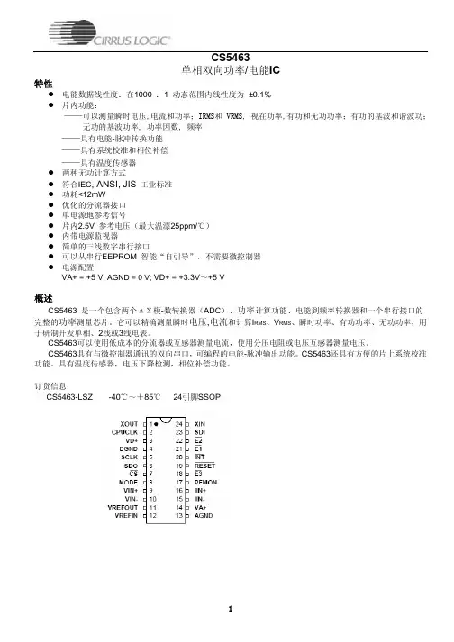
2.2 引脚排列及功能CS5460的引脚排列如图2所示。
各引脚的功能如下:1脚XOUT:晶体振荡器输出;2脚CPUCLK:CPU时钟输出;3脚VD+:数字电路电源正极;4脚DGND:数字地;5脚SCLK:串行时钟输入;6脚SDO:串行数据输出;7脚CS:片选;8脚NC:空脚;9脚VIN+:差分电压正输入端;10脚VIN-:差分电压负输入端;11脚VREFOUT:参考电压输出;12脚VREFIN:参考电压输入;13脚VA-:模拟地;14脚VA+:模拟电源正极;15脚IIN-:差分电流负输入端;16脚IIN+:差分电流正输入端;17脚PFMON:电源掉电监视输出;18脚NC:空脚;19脚RESET:复位输入;20脚INT:中断输出;21脚EOUT:电能脉冲输出;22脚EDIR:功率方向指示输出;23脚SDI:串行数据输入;24脚XIN:晶体振荡器输入。
基于CS5463的新型多功能电能表电路设计0 引言传统感应式电能表用其结构和原理上的制约,通常存在着测量范围小,稳定性差,精度低等缺点而不能适应社会发展的需要。
随着微电子技术和单片机的发展和普及,新型智能化测控技术迅速发展。
以单片机为核心的电子式电能表显示了其明显的优势。
本文采用单片机作为仪表的主控制器,并由Cirrus Logic 公司的电能计量芯片负责采集数据,因而具有性价比高,抗干扰能力强,测量精度高等优点。
1 电路工作原理本设计采用开关稳压电源,将220V 交流市电整流稳压为模拟、数字两路+5 V 电压,为整个电表电路供电。
该系统通过电流互感器检测电流信号,而通过分压电阻采集电压信号,然后将其送入单相功率/电能集成芯片CS5463 内,并在片内完成信号采样、计算和误差校正等。
整个过程在单片机PLC916 控制下进行。
其原理框图如图1 所示。
2 专用计量芯片CS5463CS5463 是内含两个△∑模-数转换器(ADC)、高速电能计算功能和一个串行接口的高集成△∑模―转转换器。
它可以精确测量和计算有功电能、瞬时功率、无功功率、IRMS 和VRMS,可用于研制开发单相2 线或3 线电表。
CS5463 可以使用低成本的分流器或电流互感器来测量电流,并使用分压电阻或电压互感器来测量电压。
CS5463 具有与微控制器通讯的双向串口,其芯片的脉冲输出频率与有功能量成正比。
CS5463 具有方便的片上AC/DC 系统校准功能。
其“自引导”的特点使得CS5463 能独自工作,并在系统上电后自动初始化。
在自引导模式,CS5463 可从一个外部EEP-ROM 中读取校准数据和启动指令。
使用该模式,CS5463 在工作时不需要外加微控制器,因此,当电表用于大批量住宅电能测量时,可降低电表的成本。
CS5463 可以提供瞬时电压/电流/功率数据采样及有功能量、IRMS、VRMS 的周期计算结果。
为适应低价测量应用,CS5463 也能在给定引脚上输出脉冲串,输出的脉冲数与。