IEC61850通信规约转换软件Demo使用手册xt
- 格式:doc
- 大小:570.50 KB
- 文档页数:21
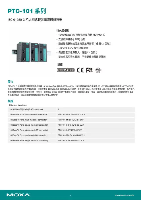
PTC-101系列IEC61850-3乙太網路轉光纖媒體轉換器特色與優點•10/100BaseT(X)自動協商和自動MDI/MDI-X•支援故障轉移(LFPT)功能•透過繼電器輸出發出電源故障告警(僅限LV型號)•-40°C至85°C操作溫度範圍•備援雙直流電源輸入(僅限LV型號)•整合式高可靠性電源,不需要外接電源變壓器認證簡介PTC-101乙太網路轉光纖媒體轉換器可將10/100BaseT(X)轉換為100BaseFX。
此系列轉換器具備光纖用的SC、ST或LC接頭可供選擇。
PTC-101轉換器除了讓您省去額外的電線配置,也同時支援IEEE802.3和IEEE802.3u/x協定,提供10/100M、全/半雙工和MDI/MDI-X自動感應等功能,為工業乙太網路應用提供完整的解決方案。
PTC-101符合IEC61850-3規範中有關操作溫度、電源輸入電壓、突波、ESD和振動的強制要求,並且採用敷形塗層和隔離式電源,讓這台媒體轉換器更適合用在各種工業應用。
規格Ethernet Interface10/100BaseT(X)Ports(RJ45connector)1100BaseFX Ports(multi-mode SC connector)PTC-101-M-SC-HV/M-SC-LV:1100BaseFX Ports(multi-mode ST connector)PTC-101-M-ST-HV/M-ST-LV:1100BaseFX Ports(single-mode SC connector)PTC-101-S-SC-HV/S-SC-LV:1100BaseFX Ports(single-mode ST connector)PTC-101-S-ST-HV/S-ST-LV:1100BaseFX Ports(multi-mode LC connector)PTC-101-M-LC-HV/M-LC-LV:1100BaseFX Ports(single-mode LC connector)PTC-101-S-LC-HV/S-LC-LV:1Magnetic Isolation Protection 1.5kV(built-in)Optical FiberWavelength1300nm1310nmMax.TX-10dBm0dBmMin.TX-20dBm-5dBmRX Sensitivity-32dBm-34dBmLink Budget12dB29dBTypical Distance 5km a4km b40km cSaturation-6dBm-3dBma.50/125µm,800MHz x km fiber optic cableb.62.5/125µm,500MHz x km fiber optic cablec.9/125µm single-mode fiber optic cabled.9/125µm single-mode fiber optic cable(80km)Power ParametersInput Voltage LV-DC models:20to72VDCHV-AC models:100to240VACHV-DC models:88to300VDCInput Current LV-DC models:150mA@20to72VDCHV-AC models:200to350mA@100to240VACHV-DC models:47mA@88VDCOverload Current Protection SupportedPower Consumption LV-DC models:150mA@20to72VDCHV-AC models:200to350mA@100to240VACHV-DC models:47mA@88VDCPhysical CharacteristicsHousing MetalDimensions152.15x126.46x66.65mm(5.99x4.86x2.62in)Weight Packaged:875g(1.92lb)Product only:690g(1.52lb)Installation DIN-rail mountingEnvironmental LimitsOperating Temperature-40to85°C(-40to185°F)Storage Temperature(package included)-40to85°C(-40to185°F)Ambient Relative Humidity5to95%(non-condensing)Standards and CertificationsEMC EN55032/24EMI CISPR32,FCC Part15B Class AEMS IEC61000-4-2ESD:Contact:8kV;Air:15kVIEC61000-4-3RS:80MHz to1GHz:3V/mIEC61000-4-4EFT:Power:4kV;Signal:4kVIEC61000-4-5Surge:Power:4kV;Signal:4kVIEC61000-4-6CS:150kHz to80MHz:10V/m;Signal:10V/mIEC61000-4-8PFMFIEC61000-4-11Environmental Testing IEC60068-2-1IEC60068-2-14IEC60068-2-2IEC60068-2-3Safety EN60950-1,UL60950-1Vibration IEC60068-2-6Power Substation IEC61850-3MTBFTime1,211,613hrsStandards MIL-HDBK-217FWarrantyWarranty Period5yearsDetails See /tw/warrantyPackage ContentsDevice1x PTC-101Series media converterDocumentation1x quick installation guide1x warranty card尺寸PTC-101-M-ST-HV(可依照需求提供其他型號)訂購資訊PTC-101-M-SC-LV Multi-mode SC20-72VDC PTC-101-M-ST-LV Multi-mode ST20-72VDC PTC-101-M-LC-LV Multi-mode LC20-72VDC PTC-101-S-SC-LV Single-mode SC20-72VDC PTC-101-S-ST-LV Single-mode ST20-72VDC PTC-101-S-LC-LV Single-mode LC20-72VDCPTC-101-M-SC-HV Multi-mode SC 85-264VAC 88-300VDCPTC-101-M-ST-HV Multi-mode ST 85-264VAC 88-300VDCPTC-101-M-LC-HV Multi-mode LC 85-264VAC 88-300VDCPTC-101-S-SC-HV Single-mode SC 85-264VAC 88-300VDCPTC-101-S-ST-HV Single-mode ST 85-264VAC 88-300VDCPTC-101-S-LC-HV Single-mode LC 85-264VAC 88-300VDC配件(選購)DIN-Rail Mounting KitsDK-DC50131-01DIN-rail mounting kit,6screwsWireless AP Mounting KitsDK-DC50131DIN-rail mounting kitWall-Mounting KitsWK-51-01Wall mounting kit with2plates(51.6x67x2mm)and6screws©Moxa Inc.版權所有.2020年12月22日更新。
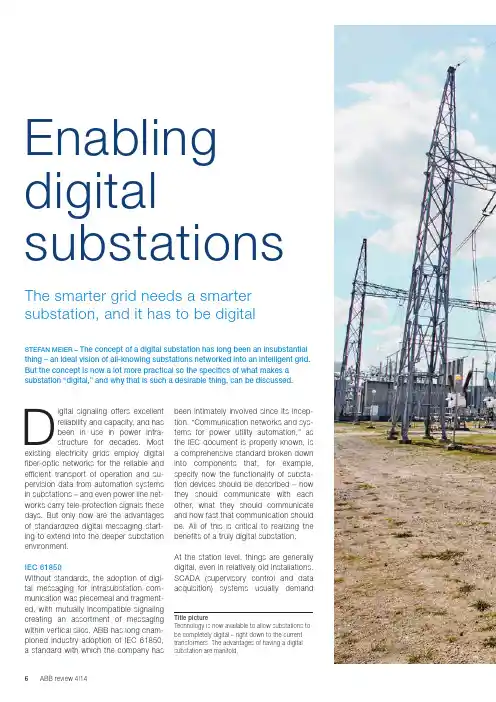
been intimately involved since its incep-tion. “Communication networks and sys-tems for power utility automation,” as the IEC document is properly known, is a comprehensive standard broken down into components that, for example, specify how the functionality of substa-tion devices should be described – how they should communicate with each o ther, what they should communicate and how fast that communication should be. All of this is critical to realizing the benefits of a truly digital substation.At the station level, things are generally digital, even in relatively old installations. SC ADA (supervisory control and data a cquisition) systems usually demand Digital signaling offers excellent reliability and capacity, and has been in use in power infra-structure for decades. Most existing electricity grids employ digital f iber-optic networks for the reliable and efficient transport of operation and su-pervision data from automation systems in substations – and even power line net-works carry tele-protection signals these days. But only now are the advantages of standardized digital messaging start-ing to extend into the deeper substation environment.IEC 61850Without standards, the adoption of digi-tal messaging for intrasubstation com-munication was piecemeal and fragment-ed, with mutually incompatible signaling creating an assortment of messaging within vertical silos. ABB has long cham-pioned industry adoption of IEC 61850, a standard with which the company has STEFAN MEIER – The concept of a digital substation has long been an insubstantial thing – an ideal vision of all-knowing substations networked into an intelligent grid. But the concept is now a lot more practical so the specifics of what makes a substation “digital,” and why that is such a desirable thing, can be discussed.The smarter grid needs a smarter substation, and it has to be digital Enabling digital substations Title picture Technology is now available to allow substations to be completely digital – right down to the currenttransformers. The advantages of having a digital substation are manifold.FOCS Robustness and reliability requirements apply to new technologies such as ABB’s fiber-optic current sensor (FOCS) too. A FOCS [1] can directly monitor current running through a high-voltage line with-out having to involve a current trans-former (CT) to step down the current to a measurable value. Eliminating the C T also eliminates the risk of open C T cir-cuits, in which life-threatening voltages can occur, and so increases safety.A FOCS exploits the phase shift in polar-ized light introduced by an electromag-netic field (the Faraday effect). The shiftis in direct proportion to the current flow-ing in the high-voltage line, around whichthe fiber carrying the light is wrapped.The measurement is digitized right atthe source and transmitted as a digitalsignal, via the process bus, to the pro-tection and control IEDs, as well as therevenue meters.Such an optical C T takes up a lot lessspace than its analog equivalent. It caneven be integrated into a disconnectingcircuit breaker (as ABB did in 2013) tocombine the functions of circuit breaker,current transformer and disconnector inone device – halving the size of a newsubstation.The FOCS is one of a range of noncon-ventional instrument transformers (NCITs)that can make things entirely digital.NCITs have to be every bit as reliable asthe equipment being replaced – and theydigital information and ABB has been selling fiber-optic “backbones” for more than two decades.Between the station level and the bays, fibers can carry digital data – conforming to IEC 61850 – but to become a true digital substation the standard has to e xtend even further.Deep digitalThe world beyond the bays is still pre-dominately analog. The conventional pri-mary equipment, like current and voltage transformers, is connected back to intel-ligent electronic devices (IEDs) using par-allel copper wires carrying analog voltage signals ➔1a. The IEDs receiving that data perform first-level analysis and often pro-vide the gateway into a digital world.But there is little advantage in keeping the data in analog form for so long and to properly earn the title of “digital substa-tion” the transition to digital must takeplace as soon as the data is gathered ➔1b.Through permanent system supervision, digital equipment reduces the need for manual intervention and the adoption of the all-digital process bus allows sensitive equipment to be relocated into the bays. The digital equipment that has to bel ocated out in the yard must be easy to fit, and every bit as robust and reliable as the analog equipment it is replacing or inter-facing to ➔2.Digital signaling offers excellent reliability and capacity, and has been in use in power infrastruc-ture for decades.1a Today 1b Tomorrow670 series 670 series REB500REB500650 series 650 seriescurrent transformer, arcing may occur as dangerously high voltages build and a copper line can suddenly carry high volt-age, putting workers and equipment at risk. Less copper brings greater safety.The digital substation dispenses with cop-per by using the digital process bus, which might use fiber optics or a wireless net-work, such as ABB’s Tropos technology.Just the removal of copper can, in some circumstances, justify the switch to digital. Going digital can cut the quantity of cop-per in a substation by 80 percent – a sub-stantial cost saving and, more importantly, a significant safety enhancement.The process bus also adds flexibility: Digital devices can speak directly to each other ➔3. For this, IEC 61850 defines the GOOSE (generic object-orientatedsubstation events)protocol for fasttransmission of bi-nary data. Part 9-2of the standard de-scribes the trans-mission of sampledvalues over Ether-net. These principlesensure the timelydelivery of high-pri-ority data via other-wise unpredictableEthernet links. ABB’s ASF range of E thernet switches fully supports this crit-ical aspect of substation messaging.are: Over the past decade ABB has sup-plied more than 300 NC ITs (combined current and voltage sensors fitted into gas-insulated switchgear) for use in Queensland, Australia, and the utility has yet to see a single failure in the primarysensor. Extensive use of NCITs makes a substation simpler, cheaper, smaller and more efficient.Not everything can be digital – analog data will continue to arrive from conven-tional current and voltage transformers, for example. But there is no reason for wholesale replacement when a stand-alone merging unit can perform the tran-sition to digital right beside the existinginstrument transformer. Fiber optics can then replace the copper cables connect-ing the primary equipment to the protec-tion and control IEDs.Process bus As a conductor, every bit of copper in a substation is a potential risk. For exam-ple, where current is incorrectly discon-nected, such as with an open secondary A FOCS can direct-ly monitor current running through a high-voltage line without having to involve a current transformer to stepdown the current to a measurable value.2 New equipment destined for use out in the yard is exposed to the elements so has to be very robust.ABB has long championed industry adoption of IEC 61850, a standard with which the company has been intimately involved since its inception.Installations ABB has been heavily involved in IEC 61850 since its inception. The stan-dard is essential to ensure that utilities can mix and match equipment from dif-ferent suppliers, but, through compli-ance testing, it also provides a bench-mark against which manufacturers can be measured.ABB deployed the first commercial IEC 61850-9-2 installation in 2011 at the Loganlea substation, for Powerlink Queens-land. The use of ABB’s IEC 61850-9-2- compliant merging units and IEDs, not to mention NCITs, makes the deployment a landmark in the evolution of substation design.That project was part of an upgrade of an existing station, an upgrade that saw it move into an IEC 61850 future, adopting digital standards for effective future-proof-ing. ABB created a retrofit solution based on specifications from Powerlink that can be applied to another five Powerlink substa-tions when they are ready for refitting.Two of those stations, Millmerran and Bulli Creek, were already upgraded in 2013 and 2014, respectively. The refurbished sub-stations have a MicroSCADA Pro SYS600 system and RTU560 gateway that manage Relion 670 protection and control IEDs, with REB500 busbar protection. These all communicate over IEC 61850-9-2 to the merging units and over IEC 61850 to the station-level devices. A fully digital substation is smaller, more reliable, has a reduced life-cycle cost and is simpler to maintain and extend than an analog one. It offers increased safety and is more efficient than its ana-log equivalent.Not every substation needs to be cata-pulted into a wholesale digital world – it depends on the substation size and type, and whether it is a new station or a retrofit of the secondary system. Different ap-proaches and solutions are required. ABB’s extensive IEC 61850 experience and portfolio of NCITs, merging units, pro-tection and control IEDs as well as station automation solutions eases utilities into the digital world. Flexible solutions allow utilities to set their own pace on their waytoward the digital substation.3 IEC 61850 makes the fully digital substation a reality.Stefan MeierABB Power Systems Baden, Switzerland *******************.com An optical CT takes up a lot less space than its analog equivalent and can even be integrated into a disconnecting circuit breaker to combine the func-tions of circuit breaker, current transformer and disconnector in one device – halv-ing the size of a new substation.Reference [1] S. Light measures current – A fiber-optic current sensor integrated into a high-voltage circuit breaker. Available: /global/scot/scot271.nsf/veritydisplay/0d948cedb40451cec1257ca900532dd0/$file/12-17%201m411_EN_72dpi.pdf。
IEC61850通信规约转换软件Demo使⽤⼿册xt IEC61850通信规约转换Demo软件使⽤⼿册北京华睿信通科技有限公司2016-3-13修订历史记录A - 增加M - 修订D - 删除⽬录IEC61850通信规约转换软件 (1)1.引⾔ (4)1.1编写⽬的及使⽤对象 (4)2.系统简介 (4)2.1产品特点 (4)2.2 性能 (4)2.3软件组成模块 (4)2.4软件运⾏环境 (5)3. 智能终端IEC61850通讯规约转换软件使⽤说明 (5)3.1 软件组成 (5)3.2第⼀次使⽤ (6)3.3⼯程配置 (9)3.3.1新增采集设备 (10)3.3.2修改采集设备 (16)3.3.3配置信息向装置下载 (16)1.引⾔1.1编写⽬的及使⽤对象本⽂档介绍智能电⼦设备IEC61850规约转换软件的组成模块,性能指标和主要功能,并详细介绍modbus规约转换为IEC61850规约的使⽤⽅法,适⽤于⼯程技术⼈员使⽤。
2.系统简介2.1产品特点●满⾜最新DL/T 860(IEC61850)通讯标准●完全⽀持国际标准IEC61850规约,并可实现其它规约对IEC 61850规约的转换。
●⽀持modbus TCP/IP ,modbus RTU2.2 性能a.系统容量●同时接⼊的终端装置数⽬:100(在pc机下vmvare fedora7 cpu2G 内存2G)b.时间特性●随系统⾃动启动●默认检索实时数据的周期为最⼩30秒钟,此参数可以设置●检索报警数据的周期为即时上送c.计算机系统(在pc机下vmvare fedora7 cpu2G 内存2G)●系统可⽤率≥99%●CPU负荷率≤25%●⽹络负荷率≤5%d.通讯能⼒●⽀持⽹络●⽀持串⼝2.3软件组成模块IEC61850规约转换Demo软件主要实现由modbus协议转换成IEC 61850协议,其数据的交换通过共享内存⽅式来实现,涉及到三个模块采集模块、实时库和61850服务模块。
I E C61850建模工具软件用户手册IEC 61850建模工具用户手册山东理工大学2013.03目录1.简介 ........................................................................................................................- 1 -2. IEC 61850配置功能 ..............................................................................................- 1 -2.1 界面..............................................................................................................- 1 -2.2 CID文件配置...............................................................................................- 2 -2.3 CID文件树形结构.......................................................................................- 3 -2.4 逻辑数据配置..............................................................................................- 5 -2.4.1 增加...................................................................................................- 5 -2.4.2 修改...................................................................................................- 7 -2.4.3 删除...................................................................................................- 8 -2.4.4 导出...................................................................................................- 9 -2.4.5 导入...................................................................................................- 9 -2.5逻辑设备维护 .......................................................................................... - 10 -2.5.1 增加................................................................................................ - 11 -2.5.2 删除................................................................................................ - 12 -2.5.3 修改................................................................................................ - 13 -2.6逻辑节点维护 .......................................................................................... - 13 -2.6.1 增加................................................................................................ - 14 -2.6.2 删除.................................................................................................- 17 -2.6.3 修改.................................................................................................- 17 -3.CID文件生成....................................................................................................... - 18 -4. CID文件格式...................................................................................................... - 18 -4.1 CDC、FC配置文件内容........................................................................... - 18 -4.2 CID文件模版内容.....................................................................................- 20 -4.3 生成CID文件内容....................................................................................- 20 -1.简介主要完成61850FTU逻辑数据的配置,配置信息生成excel文件,61850FTU配置程序通过读取excel信息保存到配置文件中。

NS3000数字化变电站自动化系统调试作业指导书(后台部分)1 目的指导NS3000数字化变电站自动化系统的后台部分的组态与调试,以规范自动化系统的调试过程,从而保证系统的质量,提高系统的可靠性与稳定性2 适用岗位本指导书适用于工程部从事数字化变电站自动化系统工程开发调试的工程部经理、项目负责人、项目工程师和调试人员3 调试流程3.1调试前准备3.1.1 检查用户资料是否齐全3.1.2 根据合同、技术协议、发货清单等资料,到库房领用项目所须硬件,并清点•SCADA机数目、配置•工作站数目、配置•打印机数目、配置•显示器数目、配置•UPS数目、配置•网络设备数目、配置•其他外设数目、配置3.2 系统安装NS3000计算机系统对计算机配置的要求•硬件:PentiumIV 1.6G以上,内存512M以上,硬盘40G 以上。
•操作系统:Windows 2000专业版或者Windows XP专业版。
•SCADA机需安装SQL Server2000的服务器及客户端工具,及SQL Server2000 SP3.•工作站需安装SQL Server2000的客户端工具, 以及SQL Server2000 SP3.•安装WINDOWS的消息队列组件.•NS3000计算机系统的安装.•若本项目有两台计算机作为远动工作站,请将这两台计算机作为一个独立的双SCADA服务器与后台双SCADA服务器分开,其安装序列号需要额外申请•安装详细步骤可参见<<NS2000安装手册>>需说明的是:目前还未将61850的相关后台程序、文件整合到NS2000后台安装盘中。
需要将bin、config文件夹下的相关程序、文本更新,使其成为支持61850的NS3000后台。
3.3 操作系统最大连接数破解功能简介:Windows XP系统限制了操作系统对外的最大连接数,默认为10(Windows 2000操作系统不存在这样的情况)。
数字继保61850参数设置说明书A.继保之星系列试验仪介绍(继保之星-6000C的主要特点)•16对光收发器,提供针对IEC61850标准规范中各种通信信息的有效编解码。
(61850-9-1,61850-9-2,GOOSE信息)•12个发送器和两个接收器,提供针对IEC60044-7/8的FT3格式的采样值报文•完整解析保护模型文件,实现电流电压通道选择、比例系数、ASDU数目、采样率、GOOSE信息等的配置,可灵活方便地与各种型号保护接口•10对开入量,8对通用开出量,实现保护的完整闭环测试•GOOSE信息报文,能够模拟丢帧和乱码•内置GPS,可进行远距离同步输出•10.4寸大屏显示•内置工控机•IRIGB对时或IEEE1588对时•24路数字采样值输出,每路均可独立配置电压和电流以及频率•12路小信号输出,每路均可独立配置电压或电流•波形显示•数字录波B.数字继保模块设置说明该模块是专门用来对9-1,9-2,9-1扩展,FT3,FT3扩展,小信号,订阅GOOSE,发布GOOSE中电流电压通道选择,ASDU数目,采样点数等信息进行设置的。
(一)9-1配置:在试验程序(比如交流试验等)主界面工具条中,点击61850网络设置按钮就可以启动该模块了,下图所示中红色圆圈指出的地方。
然后,通过界面下方的选择框可以选择9-1/9-2/9-1扩展/FT3/FT3扩展/小信号/订阅GOOSE/发布GOOSE设置窗口,如下图所示为9-1设置界面:注明:白色编辑框显示列表一,列表二和列表三(下同)➢界面说明:●ASDU数目:每帧报文中包含的采样点数目,最大为10●采样点数/20ms:20ms时间中采样点数目,最大为255●系数设置:启动后用来设置一次/二次额定值,比例系数和小信号输出等(见9-2设置)●通道设置:用来设置输出通道(列表一)●目的MAC地址:表示目的MAC地址●TPID:标识号(默认为8100,不能修改)●TCI:标识(通过设置优先级,CFI和VLanID进行修改)●APPID:装置标识ID(列表二)●LNName:逻辑节点名称●DataSetName:数据集名称●LDName:逻辑设备名称●延迟时间:设置额定延迟时间●版本号:配置版本号●状态字1/2:设置状态字1和状态字2●通道名称:设置输出通道的名称(列表三)●通道映射:用来设置映射通道➢操作说明:●鼠标左键点击[列表一]中某行[输出]列,[列表二][列表三]将同步显示对应的相关信息。
目录第一章系统概述 (1)第二章系统安装与注册 (1)2.1 系统安装 (1)2.2 目录结构 (2)2.3 系统注册 (2)第三章功能介绍 (3)3.1 整体功能概述 (3)3.2 菜单栏和工具栏 (3)3.2.1 文件 (4)3.2.2 编辑 (5)3.2.3 查看 (5)3.2.4 窗口 (7)3.2.5 帮助 (8)3.2.6 导航窗口右键菜单 (8)3.2.7 快速打开窗口 (9)3.3 版本管理 (10)3.4 导入文件 (11)3.4.1 导入单个文件 (11)3.4.2 批量导入文件 (13)3.5 导出文件 (14)3.6 网络管理 (14)3.6.1 IP地址 (15)3.6.2 GOOSE地址 (17)3.6.3 SV地址 (19)3.6.4 物理端口 (20)3.7 设备管理 (21)3.8 应用功能 (22)3.8.1数据集 (22)3.8.2 报告控制块 (23)3.8.3 实例化 (24)3.8.4 连线配置 (25)3.8.5 GOOSE/SV控制块 (28)3.8.6 定值控制块 (29)3.8.7日志/日志控制块 (29)3.8.8 运行环境配置 (30)3.9 主控窗体 (31)3.10 查看模板 (31)3.11 连线展示 (32)3.12 IEC标准模型展示 (35)3.13 CID文件分发 (35)第四章配置方法 (37)4.1 准备模型文件 (37)4.2 导入模型文件 (37)4.3 配置网络 (38)4.4 网络中添加装置 (38)4.5 配置实例化 (39)4.6 配置连线 (39)4.7 其他配置 (40)第一章系统概述IEC61850 SCD配置工具是在原有的“SCD配置器”基础之上,通过重新的架构设计和功能设计而开发出来的功能强大、界面友好的智能变电站配置工具。
新版SCD配置工具的初始版本为3.0。
在对原有“SCD配置器”的兼容上面,新工具支持其全部功能,并对算法、界面等进行了优化设计,提高了系统执行效率,完善了可操作性。
IEC61850数据库定义说明IEC61850 EyeWin2.0⼚站监控系统使⽤说明书(DbManager.exe V1.0.0.17)第⼀章概述由于IEC61850标准的引⼊使⽤,后台EyeWin20监控系统建⽴数据库的过程与以往有所不同。
以往是通过建⽴屏柜、设备,选择已有的模板(即Devtem.ini 中预定义)来建库。
使⽤了61850标准后,屏柜、设备等信息可以通过SCL⽂件来⾃动创建,屏柜、设备以及配置信息可以⾃动⽣成,简化了建库过程。
以下以PSL621D为例,详细说明了如何通过SCL⽂件定义参数数据库。
如有不明之处,请致电025-********咨询。
第⼆章通过SCL⽂件建⽴数据库2.1建⽴数据库的准备⼯作1.获取装置⼚家提供的站内各种装置的SCL⽂件,包括xml格式的⽂件(变电站描述语⾔)和与其同名的cfg格式的配置⽂件(描述与IEC61850控制变量名相对应的中⽂名)。
2.将第1步中的两类⽂件置于EYEwin20系统的SCL⽬录下,若没有则新建该⽂件夹。
3.打开\Data\PS6000.ini,在[Settings]下添加:ConfigSCL=1 代表可以在数据库打开SCL配置项;ConfigFile=1 代表打开SCL⽂件的同时从同名的cfg⽂件读取中⽂信息;2.2通过SCL⽂件建⽴数据库打开参数数据库,⽤户单击选项卡风格树型⽬录列表下端的“SCL配置”选项,双击“SCL⽂件列表”,可以看到SCL⽂件夹中的xml⽂件均显⽰在列表中,界⾯如下图所⽰:选择需要查看的⽂件,双击⽂件或者选中⽂件单击按钮,在界⾯右侧显⽰该⽂件的内容,例如双击621D.xml,右侧显⽰内容如下图:注意:如果⽆法打开⽂件并报错误,则需要注册msxml2.dll。
具体⽅法:在可选插件中找到msxml2.dll,msxml2r.dll,将其置于于系统的system32下。
然后在开始->运⾏⾥输⼊regsvr32.exe msxml2.dll,确定。
IEC 61850建模工具用户手册理工大学2013.03目录1.简介 ........................................................................................................................- 1 -2. IEC 61850配置功能 ..............................................................................................- 1 -2.1 界面 .............................................................................................................- 1 -2.2 CID文件配置 ................................................................................................- 2 -2.3 CID文件树形结构 ........................................................................................- 3 -2.4 逻辑数据配置 .............................................................................................- 5 -2.4.1 增加 ...................................................................................................- 5 -2.4.2 修改 ...................................................................................................- 7 -2.4.3 删除 ...................................................................................................- 8 -2.4.4 导出 ...................................................................................................- 9 -2.4.5 导入 ...................................................................................................- 9 -2.5逻辑设备维护 ........................................................................................... - 10 -2.5.1 增加 ................................................................................................ - 11 -2.5.2 删除 ................................................................................................ - 12 -2.5.3 修改 ................................................................................................ - 13 -2.6逻辑节点维护 ........................................................................................... - 14 -2.6.1 增加 ................................................................................................ - 14 -2.6.2 删除 .................................................................................................- 17 -2.6.3 修改 .................................................................................................- 17 -3.CID文件生成 ....................................................................................................... - 18 -4. CID文件格式 ...................................................................................................... - 19 -4.1 CDC、FC配置文件容................................................................................ - 19 -4.2 CID文件模版容 ......................................................................................... - 21 -4.3 生成CID文件容....................................................................................... - 22 -1.简介主要完成61850FTU逻辑数据的配置,配置信息生成excel文件,61850FTU 配置程序通过读取excel信息保存到配置文件中。
IEC61850之调试软件IEDScout配置使用说明1.软件配置IEDSout不用安装直接复制到目录下运行文件夹内IEDScout.exe即可,第一次运行会提示无法找到配置文件,此时选”是”在弹出的框口中选择文件夹内的OMRN55.INI即可。
软件运行后进行连接配置:a.点击“options”→configuration或者直接点击弹出配置界面。
b.在Servers配置目标机器IP地址如果需要的server已经存在则不需要建立,或在IP Address中更新需要的IP即可,如果不存在点击“New”弹出新建窗口。
Name of new server:任意(填写自己易识别的名字即可)IP Address: 填写要连接的目标机器IP地址(如MOXA工控机UC7124的IP为192.168.0.127)c.配置本机IP填入本机IP(即运行IEDscout的电脑IP地址)d.其他保持默认值即可,点”apply”“OK”保存设置返回主界面即可。
2.搜索目标服务器建立连接a.点”Actions”→”Discover”或工具栏弹出搜索框。
b.选择相应的服务器,点击”Connect”搜索目标服务器,如果找到会自动返回主窗口显示目标服务器数据目录。
c.如果在连接过程中无法找到服务器可以点击“Actions” ”Messages”或查看相当的连接信息排除是否设置不正确3.查看数据连接建立后显示的数据目录结果标识如下图:a. 在连接建立后,主窗口显示目标服务器提供的所有数据目录结构,查看某一节点数的数据请双击该节点弹出数据结构窗口查看具体数值。
b. 数据节点有GGIO,SPC,LLN0,LPHD0等。
LLN0,LPHD为设备信息描述数据,描述设备的工作状态,产品类型等。
GGIO,SPC为具体数据节点,如查电压电流等。
每个数据节点根据功能不同,带不同的功能约束(FC)属性。
MX:模拟量ST:状态量DC:描述CF:配置根据不同的FC查看数据,如MX下第一个模拟量f代表当前值(浮点数),q代表质量,t代表数据改变时间。
2000-1Text31-When a new movement in art attains a certain fashion,it is advisable to find out what its advocates are aiming at,for,however farfetched and unreasonable their principles may seem today,it is possible that in years to come they may be regarded as normal.With regard to Futurist poetry,however,the case is rather difficult,for whatever Futurist poetry may be-even admitting that the theory on which it is based may be right-it can hardly be classed as Literature.2-This,in brief,is what the Futurist says;for a century,past conditions of life have been conditionally speeding up,till now we live in a world of noise and violence and speed.Consequently,our feelings,thoughts and emotions have undergone a corresponding change.This speeding up of life,says the Futurist,requires a new form of expression.We must speed up our literature too,if we want to interpret modern stress.We must pour out a large stream of essential words,unhampered by stops,or qualifying adjectives,or finite verbs.Instead of describing sounds we must make up words that imitate them;we must use many sizes of type and different colored inks on the same page,and shorten or lengthen words at will.3-Certainly their descriptions of battles are confused.But it is a little upsetting to read in the explanatory notes that a certain line describes a fight between a Turkish and a Bulgarian officer on a bridge off which they both fall into the river-and then to find that the line consists of the noise of their falling and the weights of the officers:“Pluff!Pluff!A hundred and eighty-five kilograms.”4-This,though it fulfills the laws and requirements of Futurist poetry,can hardly be classed as Literature.All the same,no thinking man can refuse to accept their first proposition:that a great change in our emotional life calls for a change of expression.The whole question is really this:have we essentially changed?19.This passage is mainly________.[A]a survey of new approaches to art[B]a review of Futurist poetry[C]about merits of the Futurist movement[D]about laws and requirements of literature20.When a novel literary idea appears,people should try to________.[A]determine its purposes[B]ignore its flaws[C]follow the new fashions[D]accept the principles21.Futurists claim that we must________.[A]increase the production of literature[B]use poetry to relieve modern stress[C]develop new modes of expression[D]avoid using adjectives and verbs22.The author believes that Futurist poetry is________.[A]based on reasonable principles[B]new and acceptable to ordinary people[C]indicative of basic change in human nature[D]more of a transient phenomenon than literature。
IEC61850通信规约转换软件Demo使用手册xt
IEC61850通信规约转换Demo软件
使
用
手
册
北京华睿信通科技有限公司
2016-3-13
修订历史记录
A - 增加M - 修订D - 删除
目录
IEC61850通信规约转换软件 (2)
1.引言 (5)
1.1编写目的及使用对象 (5)
2.系统简介 (6)
2.1产品特点 (6)
2.2 性能 (6)
2.3软件组成模块 (6)
2.4软件运行环境 (7)
3. 智能终端IEC61850通讯规约转换软件使用说明 (7)
3.1 软件组成 (7)
3.2第一次使用 (8)
3.3工程配置 (11)
3.3.1新增采集设备 (11)
3.3.2修改采集设备 (18)
3.3.3配置信息向装置下载 (18)
1.引言
1.1编写目的及使用对象
本文档介绍智能电子设备IEC61850规约转换软件的组成模块,性能指标和主要功能,并详细介绍modbus规约转换为IEC61850规约的使用方法,适用于工程技术人员使用。
2.系统简介
2.1产品特点
●满足最新DL/T 860(IEC61850)通讯标准
●完全支持国际标准IEC61850规约,并可实现其它规约对IEC 61850规约的
转换。
●支持modbus TCP/IP ,modbus RTU
2.2 性能
a.系统容量
●同时接入的终端装置数目:100(在pc机下vmvare fedora7 cpu2G 内
存2G)
b.时间特性
●随系统自动启动
●默认检索实时数据的周期为最小30秒钟,此参数可以设置
●检索报警数据的周期为即时上送
c.计算机系统(在pc机下vmvare fedora7 cpu2G 内存2G)
●系统可用率≥99%
●CPU负荷率≤25%
●网络负荷率≤5%
d.通讯能力
●支持网络
●支持串口
2.3软件组成模块
IEC61850规约转换Demo软件主要实现由modbus协议转换成IEC 61850协议,其数据的交换通过共享内存方式来实现,涉及到三个模块采集模块、实时库和61850服务模块。
其数据流向是采集模块(如电能量modbus master)按照用户提供的modbus协议与终端里的modbus程序进行通讯,获得电能量信息,并保存在实时库里,同时根据实时库里每个智能电子终端对应的61850DA属性,写入到61850的实时库中,这样61850服务程序就能及时更新其对应的DA值,并作相应的处理,对外提供相应的服务
图一软件结构图
2.4软件运行环境
IEC61850规约转换软件正常运行时所需要的最低软硬件配置要求见下表
3. IEC61850规约转换软件使用说明
3.1 软件组成
程序包组成如下图所示
图二整个程序包组成
mmsserver: IEC61850服务程序,实现iec61850服务功能,对外提供61850服务。
commserver: 采集程序,负责与终端按照modbus协议进行通讯,获得实时数据。
sysmgr:系统维护程序。
工程配置文件:在运行程序以及维护程序所在的目录下包含了以下子目录,每个子目录包含了系统运行所需要的配置文件(注意linux下目录区分大小写)
config目录:包含prjcfg.txt工程目录信息
dbcfg目录:dbcfg.xml,是系统基础数据库库表信息,不要对它作任何修改。
FileServer目录:61850文件服务的根目录,需要上传的文件及其子目录都放在这个目录下
project目录:工程的根目录,下面放工程子目录比如yp目录,在具体工程子目录下由以下目录构成
config目录:存放配置好的采集设备参数信息
dbcfg目录:存放工程配置好的实时库配置信息
dbdata目录:存放工成配置好生成的实时库数据文件
3.2正式版本第一次使用
使用本产品前需要对软件进行注册。
按照如下步骤进行
第一步:将运行程序以及工程配置文件拷贝到所有需要注册的装置上。
第二步:在每个装置上分别运行sysmgr程序:
第三步:在PC机上运行Remotereg.exe程序(要保证pc机与各个装置网络畅通),该程序启动后会自动搜索没有注册的装置,并显示出来,如下图四,软后点击导出注册号信息,指定所要保存的文件名如图五,然后将保存的文件给北京华睿信通科技有限公司进行授权,收到授权文件后,点击导入注册信息,选择收到的授权文件,系统会显示相应的注册信息如图六,随后点击注册,等待系统远程注册,注册完毕后在下方信息栏中会显示注册结果如图七。
图四软件注册
图五保存文件
图六导入注册信息
图七注册结果
注册程序其他按钮说明:
搜索未注册装置:搜索与PC机网络相通的还没有注册的装置,注册过的装置不会返回信息。
搜索所有装置:搜索与PC机网络相通的所有装置。
此外也可以进行单台装置注册,首先选择需要注册的装置,将选中的注册号发送给北京华睿雅威公司,获得授权号,并输入到注册码里,然后点击输入,最后点击注册。
图一产品注册
3.3工程配置
运行sysmgr程序,展开数据采集设备的树形目录,点击鼠标右键增加或修改采集设备的属性。
(演示版本不具备增加设备功能,可以修改设备配置信息)
3.3.1新增采集设备
根据工程需要,可以增加采集设备,具体步骤如下:
第一步:新增采集设备。
此步骤可以设置采集设备的名称,采集数据的周期等时间参数,一般此步骤的时间参数采用默认即可。
第二步:选择通信方式。
一般采用以太网TCP-客户端的通信方式。
第三步:设置TCP参数。
此步骤需要设置采集程序与电能量终端进行通讯的IP 地址和通信端口号,因为在同一机器上IP地址设为127.0.0.1,通信端口号根据电能量终端提供的端口,默认采用502,其他参数默认即可。
第四步:设置协议参数。
采用下面默认值即可
第五步:点击工具栏上的保存按钮,将新增加的装置信息保存到配置文件中,第六步:配置61850实时数据库。
切换到实时数据库页面,选择61850实时库 右键新建数据库。
输入数据库名称默认用61850db
新建数据库表-》选择61850DA值,根据实际情况输入最大记录数,
61850参数配置:选择61850配置设置61850相关参数
61850模型文件:根据工程实际,选正确模型文件
服务端口:默认采用102
接收间隔:是指间隔多长时间都tcp端口,看是否有数据到达,默认采用100ms
超时(s):-1表示不进行数据收发超时判断,如果要设置则根据实际现场数据交互的时间间隔来设置,比如61850服务端与客户端平均60s 钟才发生一次数据交互,则这个值应该设为比60s大的数比如65。
其他的参数主要是为了检测用的,实际工程中都采用默认值即可。
第八步:配置采集实时库表,选择实时库,右键选择新建数据库表,从下拉表中选择Modbus模拟量
根据实际情况设置最大记录数,其他采用默认值增加记录。
在数据库中增加记录,根据实际情况修改实时库中的信息并保存。
根据实时数据库表的内容修改新装置记录中的内容。
修改表内容的便捷操作方法如下,将新增装置的数据库表导出,请留心系统提示的导出位置及导出文件名字然后就可以在excel中编辑数据文件,然后再将数据库表导入并保存即可。
3.3.2修改采集设备
可以参考新增采集设备操作。
3.3.3配置信息向装置下载(windows版本不需要此操作)
当所有的信息都配置好了之后,就可以将配置信息下载到装置上。
首先要确保装置上的sysmgr程序在运行,其他程序都已经关闭。
其次与装置建立连接
连接成功后就可以下载信息,如图点击工具栏中的下载按钮
点击确定,系统就会开始下载配置信息。
4.系统运行
系统配置好之后,就可以运行了
4.1首先运行mmsserver.exe
4.2在运行commserver.exe之前,要确保sysmgr所配置的ip地址对应的Modbus
slave已经运行
4.3运行viewrtdb可以查看接收到的数据
北京华睿信通科技有限公司 IEC 61850通信规约转换软件使用手册
第 21 页共 21 页。