友达全视角7寸工业液晶屏-G070VVN01.2 工控屏
- 格式:doc
- 大小:70.50 KB
- 文档页数:3
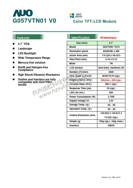
G057VTN01 V0 Color TFT-LCD Module5.7” VGA Landscape LED BacklightWide Temperature Range Mercury-free solution RoHS and Halogen-freeComplianceHigh Shock/Vibration Resistance Outline and Interface are fullycompatible with G057VN01 serials(Preliminary)Size (inch)5.7” ModelG057VN01 V210 Resolution (pixel) 640(RGB) x 480 Active Area (mm) 115.2(H) x 86.4(V)Pixel Pitch (mm) 0.18 x 0.18Mode TNLCD Surface Anti-Glare, Hardness 3HNumber of Colors 262K View Angle (L/R/U/D) 80/80/70/70 (typ.) Brightness(nit) (25℃) 500(min.), 600 (typ.)Contrast Ratio (25℃) 800:1 (typ.) Response Time (ms) 25 (typ.) LED Life (hrs.)50K Power Consumption (W) 3.74W Supply Voltage (V) 3.3V Storage Temp. (℃) -30 ~ 85 Operation Temp. (℃) -30 ~ 85Outline Dimension (mm) 144.0(H) x 104.6(V) x12.3(D) (typ.) Weight (g) 150g (typ.), 165g (max.)InterfaceCMOSTFT- LCD Interface Signal Description:Note 1: “Low” stands for 0V. “High” stands for 3.3V. “NC” stands for ”No Connection”.TFT- LCD Signal (CN1): LCD Connector: ManufacturerStarconnConnector Model Number 089H33-000100-G2-R, compatible withIMSA-9637S-33Y902 & ELCO 08-6210--033-340-800+Pin# Symbol Pin# Symbol Pin# Symbol 1 GND 12 GND 23 B3 2 DOTCLK 13 G0 24 B4 3 NC 14 G1 25 B5 4 NC 15 G2 26 GND 5 GND 16 G3 27 DE 6 R0 17 G4 28 VDD 7 R1 18 G5 29 VDD 8 R2 19 GND 30 R/L 9 R3 20 B0 31 U/D 10 R4 21 B1 32 NC 11 R522B233GNDLED Backlight Unit (CN2): Backlight Connector:ManufacturerJSTConnector Model Number SM06B-SRKS-G-TBcompatible with JST SM06B-SRSS-TB (LS) (SN)Mating Connecter Model Number JST SHR-06V-BKHF-B or compatiblePin # Symbol Pin # Symbol 1 V LED 4 GND 2 V LED 5 PWM DIM 3GND6LED ON/OFFLED Light Bar Input (CN3): Light Bar Connector ManufacturerSTM or compatible Connector Model Number P24021P6 or compatible Mating Connecter Model NumberSM06B-SHLS-TF or compatiblePin # Symbol Pin Description Cable color1 AN1 Channel 1 LED anode Red2 AN2 Channel 2 LED anode Red3 AN3 Channel 3 LED anode Red4 CA1 Channel 1 LED cathode White5 CA2 Channel 2 LED cathode Blue6 CA3Channel 3 LED cathodeBlack工业液晶屏www.hzxuhong.comReliability Test Criteria: ItemsRequired Condition Remark Temperature Humidity Bias40℃/90%,300HrNote 2 High Temperature Operation 85℃,300Hr Note 2 Low Temperature Operation -30℃,300Hr Note 2 High Temperature Storage 85℃,300 hours Note 2 Low Temperature Storage -30℃,300 hoursNote 2 Thermal Shock Test -20℃/30 min ,60℃/30 min ,100cyclesNote 2 Hot Start Test 85℃/1 Hr (min.), power on/off per 5 minutes, repeat 5 times Note 2 Cold Start Test -30℃/1 Hr (min.), power on/off per 5 minutes, repeat 5 times Note 2 Shock Test (Non-Operating) 50G, 20ms,Half-sine wave, (±X, ±Y , ±Z)Note 2Vibration Test (Non-Operating)(1)Random Wave 3.3rms, 0.5hr(X,Y,Z), 5~500hz (2)Sine Wave 6.8G, 10~400hz, 4hr40min (XYZ)Note 2ESDContact Discharge: ±8KV, 150pF(330Ω) 1sec, 8 points, 25times/pointAir Discharge: ±15KV, 150pF(330Ω) 1sec, 8 points, 25 times/pointNote 1,2Attitude TestOperating: 14,000 ft, Ramp: 2000 ft/min, 8hrs Non-operating: 40,000 ft, Ramp: 2000 ft/min, 24hrsNote 2Note1: According to EN61000-4-2 ESD class B criteria, some performance degradation is allowed. TFT-LCD module is self-recoverable, no data lost and no hardware failures after test. Note2:Water condensation is not allowed for each test items.Each test is done by new TFT-LCD module. Don’t use the same TFT-LCD module repeatedly for reliability test.The reliability test is performed only to examine the TFT-LCD module capability.To inspect TFT-LCD module after reliability test, please store it at room temperature and room humidity for 24 hours at least in advance.工业液晶屏www.hzxuhong.comVersion 0.2, Mar 2012Mechanical Characteristics:工业液晶屏www.hzxuhong.com。
MY-TFT070V2 产品用户手册版本V1.12015年3月16日版本记录目录目录 (1)第1章产品概述 (2)1.1 产品简介 (2)1.2 规格参数 (2)1.3 产品预览 (3)第2章硬件指南 (5)2.1 引脚分布 (5)2.2 信号定义 (5)2.3 电气特性 (6)2.4 时序参数 (7)第3章机械参数 (10)附录 (12)附录一联系方式 (13)附录二售后服务与技术支持 (14)第1章产品概述1.1 产品简介MY-TFT070V2是深圳米尔科技有限公司推出的7寸液晶模块,是彩色有源矩阵薄膜晶体管(TFT)液晶显示器(LCD),由TFT LCD显示器件,连接件,控制与驱动外围电路,PCB驱动底板等组成,驱动底板预留1.27mm间距的IDC排线插针(25pinX2)和0.5mm 间距的FPC连接器两种连接方式,是专为米尔科技ARM主板设计的配套LCD液晶显示模块。
1.2 产品特性MY-TFT070V2兼容三种触摸输入方式,分别为电阻式触摸输入、电容式触摸输入和外置式输入,可以根据需要任意选用需要的方式,同时只能有一种触摸方式被连接。
图1-1MY-TFT070V2带有一颗存储芯片,用来保存LCD的一些常规信息,MYiR的开发板系统能够版识别MY-TFT070V2,并根据这些信息来加载相应的驱动。
1.3 规格参数1.4 产品预览MY-TFT070V2 产品平面图如图1-2、图1-3所示:图1-2 MY-TFT070V2产品正面图图1-3 MY-TFT070V2 产品背面图第2章硬件指南2.1 接口分布底板接口分布如下图2-1所示:图2-1 底板接口分布图如上图所示,驱动底板预留1.27mm间距的50pin IDC排线插针(J1)和0.5mm间距的50pin FPC连接器(J2)两种连接方式,默认连接50pin IDC排线。
J4为电阻触摸信号连接,J5,J7分别为电容触摸控制信号连接,默认选择J5电容触摸模式。
图南光电 http://www.tndisplay.com.cnProduct SpecificationAU OPTRONICS CORPORATIONM170ETN01.1(V ) Preliminary Specification ( ) Final Specification Module Model Name 17” Color TFT-LCD M170ETN01.1CustomerDateApproved byDateChi Yin WuFeb 6, 2013Approved byPrepared byDateJia Hau JeanFeb 6, 2013Note: This Specification is subject to change without notice.AU Optronics corporationdocument version 0.01图南光电 http://www.tndisplay.com.cnProduct SpecificationAU OPTRONICS CORPORATIONM170ETN01.1Contents 1 Handling Precautions................................................................4 2 General Description ..................................................................52.1 Display Characteristics....................................................................................................... 5 2.2 Absolute Maximum Rating of Environment ........................................................................ 6 2.3 Optical Characteristics ....................................................................................................... 73 TFT-LCD Module ......................................................................113.1 Block Diagram.................................................................................................................. 11 3.2 Interface Connection........................................................................................................ 12 3.2.1 Connector Type....................................................................................................... 12 3.2.2 Connector Pin Assignment...................................................................................... 12 3.3 Electrical Characteristics.................................................................................................. 14 3.3.1 Absolute Maximum Rating ...................................................................................... 14 3.3.2 Recommended Operating Condition....................................................................... 14 3.4 Signal Characteristics ...................................................................................................... 15 3.4.1 LCD Pixel Format.................................................................................................... 15 3.4.2 LVDS Data Format .................................................................................................. 15 3.4.3 Color versus Input Data .......................................................................................... 16 3.4.4 LVDS Specification.................................................................................................. 17 3.4.5 Input Timing Specification ....................................................................................... 19 3.4.6 Input Timing Diagram .............................................................................................. 20 3.5 Power ON/OFF Sequence ............................................................................................... 214 Backlight Unit .........................................................................224.1 Block Diagram.................................................................................................................. 22 4.2 Interface Connection........................................................................................................ 23 4.2.1 Connector Type....................................................................................................... 23 4.2.2 Connector Pin Assignment...................................................................................... 25 4.3 Electrical Characteristics.................................................................................................. 26 4.3.1 Absolute Maximum Rating ...................................................................................... 26 4.3.2 Recommended Operating Condition....................................................................... 265 6 7 8Reliability Test ........................................................................28 Shipping Label ........................................................................29 Mechanical Characteristics .....................................................30 Packing Specification..............................................................318.1 Packing Flow.................................................................................................................... 31 8.2 Pallet and shipment information....................................................................................... 32document version 0.02图南光电 http://www.tndisplay.com.cnProduct SpecificationAU OPTRONICS CORPORATIONM170ETN01.1Record of RevisionVersion Date Page Old description New Description Remark0.02013/2/6AllFirst version release-document version 0.03Product SpecificationAU OPTRONICS CORPORATIONM170ETN01.11 Handling Precautions 1) 2) 3) 4) 5) 6) 7) 8) 9) Since front polarizer is easily damaged, pay attention not to scratch it. Be sure to turn off power supply when inserting or disconnecting from input connector. Wipe off water drop immediately. Long contact with water may cause discoloration or spots. When the panel surface is soiled, wipe it with absorbent cotton or other soft cloth. Since the panel is made of glass, it may break or crack if dropped or bumped on hard surface. Since CMOS LSI is used in this module, take care of static electricity and insure human earth when handling. Do not open or modify the Module Assembly. Do not press the reflector sheet at the back of the module to any directions. In case a TFT-LCD Module has to be put back into the packing container slot after once it was taken out from the container, do not press the center of the LED lightbar edge. Otherwise the TFT-LCD Module may be damaged. Insert or pull out the interface connector, be sure not to rotate nor tilt it of the TFT-LCD Module. Do not twist nor bend the TFT -LCD Module even momentary. It should be taken into consideration that no bending/twisting forces are applied to the TFT-LCD Module from outside. Otherwise the TFT-LCD Module may be damaged. Please avoid touching COF position while you are doing mechanical design. When storing modules as spares for a long time, the following precaution is necessary: Store them in a dark place. Do not expose the module to sunlight or fluorescent light. Keep the temperature between 5℃ and 35℃ at normal humidity.10) 11)12) 13)document version 0.04Product SpecificationAU OPTRONICS CORPORATIONM170ETN01.12 General Description This specification applies to the 17 inch wide Color a-Si TFT-LCD Module M170ETN01.1. The display supports the SXGA+ (1280(H) x 1024(V)) screen format and 16.7M colors (RGB 6-bits + Hi-FRC data). The input interface is Dual channel LVDS and this module doesn’t contain an driver board for backlight.2.1 Display Characteristics The following items are characteristics summary on the table under 25℃ condition:ITEMS Screen Diagonal Active Area Pixels H x V Pixel Pitch Pixel Arrangement Display Mode White Luminance ( Center ) Contrast Ratio Response Time Power Consumption (LCD Module + Backligh unit) Weight Outline Dimension Electrical Interface Support Color Surface Treatment Temperature Range Operating Storage (Shipping) RoHS Compliance TCO Compliance Unit [mm] [mm] [mm] [cd/m2] [msec] [Watt] SPECIFICATIONS 432 (17.0”) 337.920(H) × 270.336(V) 1280 × 3(RGB) × 1024 0.264(per one triad) × 0.264 R.G.B. Vertical Stripe Normally White 250 (Typ.) 1000 : 1 (Typ.) 5 (Typ., on/off) 9.91 (Typ.) LCD module : PDD (Typ.)=3 @ Black pattern,Fv=60Hz Backlight unit : PBLU (Typ.) =6.91 @Is=60mA 1273 (Typ.) 358.5(H) x 296.5(V) x 10.3(D) (Typ.) Dual Channel LVDS 16.7M colors (RGB 6-bits +Hi-FRC data) Anti-glare type, Hardness 3H 0 to +50 -20 to +60 RoHS Compliance TCO6.0 Compliance[Grams] [mm] [oC] [oC] -document version 0.05Product SpecificationAU OPTRONICS CORPORATIONM170ETN01.12.2 Absolute Maximum Rating of Environment Permanent damage may occur if exceeding the following maximum rating. Symbol TOP TGS HOP TST HST Description Operating Temperature Glass surface temperature (operation) Operation Humidity Storage Temperature Storage Humidity Min. 0 0 5 -20 5 Max. +50 +65 90 +60 90 Unit [ C] [ C] [%RH] [oC] [%RH]o oRemark Note 2-1 Note 2-1Function judged onlyNote 2-1Note 2-1: Temperature and relative humidity range are shown as the below figure. 1. 90% RH Max ( Ta ≦39℃) 2. Max wet-bulb temperature at 39℃ or less. ( Ta ≦39℃) 3. No condensationOperating RangeStorage Rangedocument version 0.06Product SpecificationAU OPTRONICS CORPORATIONM170ETN01.12.3 Optical Characteristics The optical characteristics are measured on the following test condition. Test Condition: 1. Equipment setup: Please refer to Note 2-2. 2. Panel Lighting time: 30 minutes 3. VDD=5.0V, Fv=60Hz,Is=60mA,Ta=25℃Symbol Description White Luminance (Center of screen) Min. 200 75 600 75 75 70 70 75 75 70 70 TBD TBD TBD TBD TBD TBD Typ. 250 80 1000 85 85 80 80 88 88 85 85 3.8 1.2 5 TBD TBD TBD TBD TBD TBD Max. 5.5 2.5 8 TBD TBD TBD TBD TBD TBD By SR-3 [msec] Note 2-6 By TRD-100 [degree] Note 2-5 By SR-3 Unit[cd/m2]Remark Note 2-2 By SR-3 Note 2-3 By SR-3Lw Luni CR θR θL ΦH ΦL θR θL ΦH ΦL TR TF Rx Ry Gx Gy Bx By Wx Wy CT FdBLuminance Uniformity (9 points) Contrast Ratio (Center of screen) Horizontal Viewing Angle (CR=10) Vertical Viewing Angle (CR=10) Horizontal Viewing Angle (CR=5) Vertical Viewing Angle (CR=5) Right Left Up Down Right Left Up Down Rising Time Response Time Falling Time Rising + Falling Red x Red y Green x Color Coordinates (CIE 1931) Green y Blue x Blue y White x White y Crosstalk Flicker (Center of screen)[%]-Note 2-4 By SR-30.283 0.313 0.343 0.299 0.329 0.359 1.5 -20 [%] [dB] Note 2-7 By SR-3 Note 2-8 By SR-3document version 0.07Product SpecificationAU OPTRONICS CORPORATIONM170ETN01.1Note 2-2: Equipment setup :Photo detector (SR-3, TRD-100)Measured distance (50cm)LCD PanelTFT-LCD ModuleCenter of the screen Note 2-3: Luminance Uniformity Measurement Definition:Luminance Uniformity =Minimum Luminance of 9 Points (P1 ~ P9) Maximum Luminance of 9 Points (P1 ~ P9)a.Test pattern: White Patterndocument version 0.08Product SpecificationAU OPTRONICS CORPORATIONM170ETN01.1Note 2-4: Contrast Ratio Measurement Definition:Contrast Ratio =Luminance of White pattern Luminance of Black patterna. Measured position: Center of screen (P5) & perpendicular to the screen (θ=Φ=0°) Note 2-5: Viewing angle measurement Definition: The angle at which the contrast ratio is greater than 10 & 5 . a. Horizontal view angle: Divide to left & right (θL & θR) Vertical view angle: Divide to up & down (ΦH &ΦL)Note 2-6: Response time measurement The output signals of photo detector are measured when the input signals are changed from “Black” to “White” (rising time, TR), and from “White” to “Black” (falling time, TF), respectively. The response time is interval between the 10% and 90% of optical response. (Black & White color definition: Please refer section 3.4.3)%TFTR100 90 Optical response 10 0 1 Frame 1 Frame White Black B lack W hitedocument version 0.09Product SpecificationAU OPTRONICS CORPORATIONM170ETN01.1Note 2-7: Crosstalk measurement Definition: CT = Max. (CTH,CTV); Where a.Maximum Horizontal Crosstalk : CTH = Max. (| YBL – YAL | / YAL × 100 %, | YBR – YAR | / YAR × 100 %); Maximum Vertical Crosstalk: CTV = Max. (| YBU – YAU | / YAU × 100 %, | YBD – YAD | / YAD × 100 %); b. YAU, YAD, YAL, YAR = Luminance of measured location without Black pattern YBU, YBD, YBL, YBR = Luminance of measured location with Black patternNote 2-8: Flicker measurement a. Test pattern: It is listed as following. Gray level = L0Gray level = L127R: Red, G: Green, B:Blue b. Measured position: Center of screen (P5) & perpendicular to the screen (θ=Φ=0°)document version 0.010Product SpecificationAU OPTRONICS CORPORATIONM170ETN01.13 TFT-LCD Module 3.1 Block Diagram The following shows the block diagram of the 17 inch Color TFT-LCD Module.ConnectorLVDS Signal Signal VDDDC/DCConverterGamma Correction G1 D1 X-Driver IC D3840AUO ASICTiming Controller Mini LVDS TransmitterTFT-LCD1280(x3) x 1024 Pixels G1024LVDSReceiverASIC Control Boarddocument version 0.011Product SpecificationAU OPTRONICS CORPORATIONM170ETN01.13.2 Interface Connection 3.2.1 Connector Type Manufacturer Part Number Mating Connector Manufacturer Part Number P-TWOAL230F-A0G1D-PTFT-LCD ConnectorSTMMSCKT2407P30HBJAEFI-XB30SSRLAHF16JAE FI-X30HL (Locked Type)3.2.2 Connector Pin Assignment PIN # 1 2 3 4 5 6 7 8 9 10 11 12 13 14 15 16 17 18 19 20 21 22 23 24 25 26 Symbol RxO0RxO0+ RxO1RxO1+ RxO2RxO2+ GND RxOCLKRxOCLK+ RxO3RxO3+ RxE0RxE0+ GND RxE1RxE1+ GND RxE2RxE2+ RxECLKRxECLK+ RxE3RxE3+ GND NC NC Description Negative LVDS differential data input (Odd data) Positive LVDS differential data input (Odd data) Negative LVDS differential data input (Odd data) Positive LVDS differential data input (Odd data) Negative LVDS differential data input (Odd data) Positive LVDS differential data input (Odd data) Ground Negative LVDS differential clock input (Odd clock) Positive LVDS differential clock input (Odd clock) Negative LVDS differential data input (Odd data) Positive LVDS differential data input (Odd data) Negative LVDS differential data input (Even data) Positive LVDS differential data input (Even data) Ground Negative LVDS differential data input (Even data) Positive LVDS differential data input (Even data) Ground Negative LVDS differential data input (Even data) Positive LVDS differential data input (Even data) Negative LVDS differential clock input (Even clock) Positive LVDS differential clock input (Even clock) Negative LVDS differential data input (Even data) Positive LVDS differential data input (Even data) Ground No connection (for AUO test only. Do not connect) No connection (for AUO test only. Do not connect)12Remarkdocument version 0.0Product SpecificationAU OPTRONICS CORPORATIONM170ETN01.127 28 29 30NC VDD VDD VDDNo connection (for AUO test only. Do not connect) Power Supply Input Voltage Power Supply Input Voltage Power Supply Input Voltagedocument version 0.013Product SpecificationAU OPTRONICS CORPORATIONM170ETN01.13.3 Electrical Characteristics 3.3.1 Absolute Maximum Rating Permanent damage may occur if exceeding the following maximum rating. Symbol VDD Description Power Supply Input Voltage Min GND-0.3 Max 6.0 Unit [Volt] Remark Ta=25℃3.3.2 Recommended Operating Condition Symbol VDD IDD PDD IRush VDDrp Description Power supply Input voltagePower supply Input Current (RMS)Min 4.5 -Typ 5.0 0.6 0.72 3 3.6Max 5.5 0.72 0.87 3.6 4.32 3.0 500Unit [Volt] [A] [A]RemarkVDD= 5.0V, Black Pattern, Fv=60Hz VDD= 5.0V, Black Pattern, Fv=75HzVDD Power Consumption Inrush Current Allowable VDD Ripple Voltage[Watt] VDD= 5.0V, Black Pattern, Fv=60Hz [Watt] VDD= 5.0V, Black Pattern, Fv=75Hz [A] Note 3-1--[mV] VDD= 5.0V, Black Pattern, Fv=75HzNote 3-1: Inrush Current measurement: Test circuit:The duration of VDD rising time: 470us.document version 0.0 14Product SpecificationAU OPTRONICS CORPORATIONM170ETN01.13.4 Signal Characteristics 3.4.1 LCD Pixel Format1 1st Line 2 1279 1280 R G B R G BR G B R GB1024th Line R G B R G BR G B R G B3.4.2 LVDS Data FormatNote 3-2: a. O = “Odd Pixel Data” E = “Even Pixel Data” nd b. Refer to 3.4.1 LCD pixel format, the 1st data is 1 (Odd Pixel Data), the 2 data is 2 (Even Pixel Data) and the last data is 1280 (Even Pixel Data).document version 0.015Product SpecificationAU OPTRONICS CORPORATIONM170ETN01.13.4.3 Color versus Input Data The following table is for color versus input data (8bit). The higher the gray level, the brighter the color.document version 0.016Product SpecificationAU OPTRONICS CORPORATIONM170ETN01.13.4.4 LVDS Specification a. DC Characteristics: Symbol VTH VTL │VID│ VCM Description LVDS Differential Input High Threshold LVDS Differential Input Low Threshold LVDS Differential Input Voltage LVDS Common Mode Voltage Min -100 100 +1.0 Typ +1.2 Max +100 600 +1.5 Units [mV] [mV] [mV] [V] VTH-VTL = 200mV Condition VCM = 1.2V VCM = 1.2VLVDS Signal Waveform: Use RxOCLK- & RxOCLK+ as example.RxOCLK-RxOCLK+document version 0.017Product SpecificationAU OPTRONICS CORPORATIONM170ETN01.1b. AC Characteristics: Symbol Description Maximum deviation of input clock frequency during Spread Spectrum FMOD Maximum modulation frequency of input clock during Spread Spectrum 200 KHz Min Max Unit RemarkFDEV-±3%Freq Fmax Fclk * FDEV Fclk Fmin 1 FMOD < Spread Spectrum> TimeFclk: LVDS Clock Frequencydocument version 0.018Product SpecificationAU OPTRONICS CORPORATIONM170ETN01.13.4.5 Input Timing Specification It only support DE mode, and the input timing are shown as the following table. Symbol Tv Tdisp (v) Tblk (v) Fv Th Tdisp (h) Tblk (h) Fh Tclk Fclk LVDS Clock Horizontal Section Vertical Section Description Period Active Blanking Frequency Period Active Blanking Frequency Period Frequency Min. 1036 1024 12 50 730 640 90 37.8 50 51.8 Typ. 1066 1024 42 60 844 640 204 54 60 64 Max. 1873 1024 849 76 1320 640 680 68.4 76 93.7 Unit Th Th Th Hz Tclk Tclk Tclk KHz ns MHz Note 3-3 1/Fclk Note 3-4 RemarkNote 3-3: The equation is listed as following. Please don’t exceed the above recommended value. Fh (Min.) = Fclk (Min.) / Th (Min.); Fh (Typ.) = Fclk (Typ.) / Th (Typ.); Fh (Max.)= Fclk (Max.) / Th (Min.); Note 3-4: The equation is listed as following. Please don’t exceed the above recommended value. Fclk (Min.) = Fv (Min.) x Th (Min.) x Tv (Min.); Fclk (Typ.) = Fv (Typ.) x Th (Typ.) x Tv (Typ.); Fclk (Max.) = Fv (Max.) x Th (Typ.) x Tv (Typ.);document version 0.019Product SpecificationAU OPTRONICS CORPORATIONM170ETN01.13.4.6 Input Timing DiagramTv M pixel Tblk(v) Tdisp(v) Y Th N LineXDEN RGB DataLineInvalid Data1Line2Line3Line4LineNLineInvalid DataCLKTclkThTdisp(h)Tblk(h)DERGB Data Pixel Pixel Pixel Pixel (Odd) M-7 M-5 M-3 M-1Invalid DataPixel Pixel Pixel Pixel Pixel Pixel 1 3 5 7 9 11Pixel Pixel Pixel M-5 M-3 M-1Invalid DataPixel Pixel 1 3RGB Data Pixel Pixel Pixel Pixel (Even) M-6 M-4 M-2 MInvalid DataPixel Pixel Pixel Pixel Pixel Pixel 2 4 6 8 10 12PixelPixel M-4PixelM-2 MInvalid DataPixel Pixel 2 4document version 0.020Product SpecificationAU OPTRONICS CORPORATIONM170ETN01.13.5 Power ON/OFF Sequence VDD power,LVDS signal and backlight on/off sequence are as following. LVDS signals from any system shall be Hi-Z state when VDD is off.Backlight OffT190% 90% 10%VDD10%T2T5T6T7LVDS SignalVALID DATA T3 T4 Backlight On Backlight OffVSLEDBacklight OffPower Sequence TimingSymbol Min.T1 T2 T3 T4 T5 T6 T7 0.5 0 500 100 0 0 1000Value Typ.-Max.10 50 50Unit[ms] [ms] [ms] [ms] [ms] [ms] [ms]RemarkNote 3-5 Note 3-6 Note 3-6-150 -Note 3-5 : Recommend setting T5 = 0ms to avoid electronic noise when VDD is off. Note 3-6 : During T5 and T6 period , please keep the level of input LVDS signals with Hi-Z state.document version 0.021Product SpecificationAU OPTRONICS CORPORATIONM170ETN01.14 Backlight Unit 4.1 Block Diagram The following shows the block diagram of the 17 inch Backlight Unit. And it includes 36 pcs LED in the LED light bar. (4 strings and 9 pcs LED of one string).+ VS -ISISISISConnectorVSLEDCh1Ch2Ch3Ch4document version 0.022Product SpecificationAU OPTRONICS CORPORATIONM170ETN01.14.2 Interface Connection 4.2.1 Connector Type Manufacturer Backlight Connector Part Number Manufacturer Mating Connector Part Number H112K-P06N-13B (Locking type) 3707K-S06N-21R ENTERY ENTERYBacklight Connector dimension:H × V × D = 13.9 × 3.00 × 4.25, Pitch = 1.0(unit = mm )document version 0.023Product SpecificationAU OPTRONICS CORPORATIONM170ETN01.1Mating Connector dimension:document version 0.024Product SpecificationAU OPTRONICS CORPORATIONM170ETN01.14.2.2 Connector Pin Assignment Pin# 1 2 3 4 5 6 Symbol Ch1 Ch2 VSLED VSLED Ch3 Ch4 Description LED Current Feedback Terminal (Channel 1) LED Current Feedback Terminal (Channel 2) LED Power Supply Voltage Input Terminal LED Power Supply Voltage Input Terminal LED Current Feedback Terminal (Channel 3) LED Current Feedback Terminal (Channel 4) RemarkPIN1document version 0.025Product SpecificationAU OPTRONICS CORPORATIONM170ETN01.14.3 Electrical Characteristics 4.3.1 Absolute Maximum RatingPermanent damage may occur if exceeding the following maximum rating. (Ta=25 ) Remark100% duty ratio Duty ratio 10% Pulse time=10 msSymbol IsDescription LED String CurrentMin 0Max 90 150Unit [mA] [mA]℃≦Duty ratio= (A / B) X 100% ;(A: Pulse time, B: Period)4.3.2 Recommended Operating Condition (Ta=25℃)Symbol Description Min. Typ. Max. Unit Remark 100% duty ratio of LED chip Is=60mA @ 100% duty ratio; Note 4-1 Is=60mA @ 100% duty ratio; Note 4-2Is Vs ∆Vs PBLU LTLEDLED String Current LED String Voltage Maximum Vs Voltage Deviation of light bar LED Light Bar Power Consumption LED Life Time25.260 28.8 6.91 -66 32.4 1.8 8.55 -[mA] [Volt] [Volt] [Watt] [Hour]30,000Note 4-3 Note 4-4document version 0.026Product SpecificationAU OPTRONICS CORPORATIONM170ETN01.1Note 4-1: Vs (Typ.) = VF (Typ.) X LED No. (one string); a. VF: LED chip forward voltage, VF (Min.)=2.8V, VF(Typ.)=3.2V, VF(Max.)=3.6V b. The same euqation to calculate Vs(Min.) & Vs (Max.) for respective VF (Min.) & VF(Max.);Note 4-2: ∆Vs (Max.) = ∆VF X LED No. (one string); a. ∆VF: LED chip forward voltage deviation; (0.2 V , each Bin of LED VF) Note 4-3: PBLU (Typ.) = Vs (Typ.) X Is (Typ.) X 4 ; ( 4 is total String No. of LED Light bar) PBLU (Max.) = Vs (Max.) X Is (Max.) X 4 ; Note 4-4: Definition of life time: a. Brightness of LED becomes to 50% of its original value b. Test condition: Is = 60mA and 25℃ (Room Temperature)document version 0.027Product SpecificationAU OPTRONICS CORPORATIONM170ETN01.15 Reliability Test AUO reliability test items are listed as following table. (Bare Panel only) ItemsTemperature Humidity Bias (THB) High Temperature Operation (HTO) Low Temperature Operation (LTO) High Temperature Storage (HTS) Low Temperature Storage (LTS) Vibration Test (Non-operation)ConditionTa= 50℃, 80%RH, 300hours Ta= 50℃, 50%RH, 300hours Ta= 0℃, 300hours Ta= 60℃, 300hours Ta= -20℃, 300hours Acceleration: 1.5 Grms Wave: Random Frequency: 10 - 200 Hz Sweep: 30 Minutes each Axis (X, Y, Z) Acceleration: 50 G Wave: Half-sine Active Time: 20 ms Direction: ±X, ±Y, ±Z (one time for each Axis) Height: 61 cm, package test -20℃/30min, 60℃/30min, 100 cycles On/10sec, Off/10sec, 30,000 cycles Contact Discharge: ± 15KV, 150pF(330Ω ) 1sec, 8 points, 25 times/ point.RemarkShock Test (Non-operation) Drop Test Thermal Shock Test (TST) On/Off TestNote 5-1ESD (Electro Static Discharge) Air Discharge: ± 15KV, 150pF(330Ω ) 1sec 8 points, 25 times/ point. Altitude Test Operation:18,000 ft Non-Operation:40,000 ftNote 5-2Note 5-1: a. A cycle of rapid temperature change consists of varying the temperature from -20℃ to 60℃, and back again. Power is not applied during the test. b. After finish temperature cycling, the unit is placed in normal room ambient for at least 4 hours before power on. Note 5-2: EN61000-4-2, ESD class B: Certain performance degradation allowed No data lost Self-recoverable No hardware failures.document version 0.028Product SpecificationAU OPTRONICS CORPORATIONM170ETN01.16 Shipping Label The label is on the panel as shown below:M170ETN01.1Note 6-1: For Pb Free products, AUO will addfor identification. for identification. for identification.Note 6-2: For RoHS compatible products, AUO will addNote 6-3: For China RoHS compatible products, AUO will addNote 6-4: The Green Mark will be presented only when the green documents have been ready by AUO Internal Green Team.document version 0.0297 Mechanical CharacteristicsAvoid touching COF position when doing mechanical designVer 0.08 Packing Specification 8.1 Packing Flow面板依序貼附保護膜裝入靜電袋, 面板依序貼附保護膜裝入靜電袋,P 板朝上依序放入紙箱中, 板朝上依序放入紙箱中,滿箱裝 8pcsCorner angle Stretch filmMoisture-proof filmLabelPET bandCorner anglePalletVer 0.08.2 Pallet and shipment informationSpecification Item Q'ty Panel Cushion Box Packing Box Pallet 1 1 1 8 pcs/Box 1 Dimension 358.5(H)mm × 296.5(V)mm × 10.3(D)mm 434(L)mm x 278(W)mm x 390(H)mm 434(L)mm x 278(W)mm x 390(H)mm 1150(L)mm x 890(W)mm x 132(H)mm 1150(L)mm x 890(W)mm x 131(H)mm Weight(kg) 1.45 0.95 0.90 13.45 12.00 334.8 without Panel & cushion with panel & cushion RemarkPallet after Packing 18 boxes/palletVer 0.0。
深圳市国显科技有限公司Shenzhen K&D Technology Co.,LtdSPECIFICATIONFORLCD MODULECustomer:Product Model: KD070D10-50NB-A5Sample code:Approved byDesigned by Checked by Array※The specification of “TBD” should refer to the measured value of sample . If there is difference between the design specification and measured value, we naturally shall negotiate and agree toRevision HistoryVersion Contents Date NoteA Original 2012-5-5B Add the specification of backlight 2012-10-9ContentsNo. Item Page1. Numbering System 4/262 Scope 5/263 Normative Reference 5/264 Definitions5/265 Technology Specifications7/266 Circuit block diagram 14/267 Reliability Test Condition and Methods 16/268 Inspection standard17/269 Handling Precautions23/2610 Precaution for use24/2611 Dimensional Outline25/2612 Packaging Drawing 26/261 Numbering System— (1) (2) (3) (4) (5) (6) (7) (8)2 ScopeThis specification applies to the TFT LCD module which is designed and manufactured by LCM Factory of Shenzhen K&D Technology Co.,Ltd.3 Normative ReferenceGB/T4619-1996 《Liquid Crystal Display Test Method》GB/T2424 《Basic environmental Testing Procedures for Electric and Electronic Products.》GB/T2423 《Basic Testing Procedures for Electric and Electronic Products》IEC61747-1 《SIXTH PARTGB2828`2829-87《National Standard of PRC》4 Definitions4.1 Definitions of VopThe definitions of threshold voltage Vth1, Vth2 the following typical waveforms are applied on liquid crystal by the method of equalized voltage for each duty and bias.【 selected waveform 】【 non-selected waveform 】① Vth1: The voltage which the brightness of segment indicates 50% of saturated value on the conditions of selected waveform(f f=80Hz, Φ=10°θ=270° at 25℃)② Vth2: The voltage which the brightness of segment indicates 50% of saturated value on the conditions of non-selected waveform(f f=80Hz, Φ=10°θ=270° at 25℃)③ Vop: (Vth1(50%)+Vth2(50%))/2 (f f=80Hz, Φ=10°θ=270° at 25℃)4.2 Definition of Response Time Tr, TdTr: The time required which the brightness of segment①becomes 10% from 100% when waveform is switched toselected one from non-selected one. (f f=80Hz, Φ=10°θ=270° at 25℃)②ss of segmentTd: The time required which the brightneselected one from selected one. (f f=80Hz, Φ=10°θ=270° at25℃)4.3 Definition of Contrast Ratio CrCr=A/B① A: Segments brightness in case of non-selected waveform② B: Segments brightness in case of selected waveform4.4 Definition of Angle and Viewing RangeAngular Graph: Constrast RatioSuch as:Viewing Angle Range:80(Cr>2) Horizontal70(Cr>2) Vertical5 Technology Specifications5.1 FeatureThis single-display module is suitable for use in Multidedia Player products. The LCD adopts one backlight with High brightness 18-lamps white LED.1) Construction: 7〞а-Si color TFT-LCD ,White LED backlight and FPC. 2) LCD:2.1 Amorphous-TFT 7-inch display, transmissive, normally white type. 2.2 800(RGB)×480 dots Matrix. 2.3 Narrow-contact ledge technique. 3) RGB interface.4) Video signal interface: Parallel RGB.5.2 Mechanical SpecificationsItem Specifications UnitDimensional outline 164.9(W) ×100.0(H) ×3.4(D) mmActive area 154.08(W) × 85.92(H) mm Pixel size 63.2(W) ×RGB×179(H) um Resolution 800(RGB) ×480 pixelLuminance250(TYP ) cd/m25.3 Absolute Max. RatingItem Symbol ValuesUnit RemarkMin. MaxPower voltageDV DD -0.5 5.0 V AV DD -0.5 15 VV GH -0.3 40 V V GL -20 0.3 V Operation temperature T OP -10 60 ℃ Storage temperatureT ST -20 70 ℃Note: The absolute maximum rating values of this product not allowed to be exceeded at any times. Should be module be used with any of absolute maximum ratings exceeded. The characteristics of the module may not be recovered, or in an extreme case, the module may be permanently destroyed.5.4 Electrical Characteristics Note 1Item SymbolValuesUnit Remark Min. Typ MaxPower voltage DV DD 3.0 3.3 3.6 V Note2 AV DD 10.1 10.3 10.5 VV GH 17.5 18 18.5 VV GL -8.5 -8 -7.5 VInput signal voltage V COM 3.1 3.3 3.4 VInput logic high voltage V IH 0.7DV DD- DV DD VNote 3 Input logic low voltage V IL 0 -0.3DV DD VNote 1:Be sure to apply DV DD and V GL to the LCD first, and then apply V GH . Note 2: DV DD setting should match the signals output voltage(refer to Note 3) of Customer’s system board.Note 3: DCLK,HS.VS,RESET,U/D,L/R,DE,R0-R7,G0-G7, G0-G7,MODE,DITHB.5.5 Optical specificationsItem Symbol ConditionValuesUnit Remark Min. Typ. Max.Viewing angle (CR≥ 10) θLΦ=180°(9o’clock)70 80 -degreeNote 1 θRΦ=0°(3 o’clock)70 80 -θTΦ=90°(12o’clock)60 70 -θBΦ=270°(6o’clock)65 75 -ResponsetimeT ONNormalθ=Φ=0° - 10 20msecNote3T OFF -1530msecNote3Contrast ratio CR 350500--Note4Color chromaticity W X 0.249 0.2990.349- Note 2Note 5Note 6 W Y 0.281 0.3310.381-Luminance L 200250 -cd/m2Note6Luminance uniformity Y U 70 80 - % Note6,7Test Conditions:1. DVDD=3.3V, I LED=120mA, the ambient temperature is 25.℃2. The test systems refer to Note 2.Note 1: Definition of viewing angle rangeNote 2: Definition of optical measurement system.The optical characteristics should be measured in dark room. After 30minutes operation, the optical properties are measured at the center point of the LCD screen. (Viewing angle is measured by ELDIM-EZ contrast/Height :1.2mm ,Response time is measured by Photo detector TOPCON BM-7, other items are measured by BM-5A/ Field of view: 1° /Height: 500mm.)Normal line Φ=270°6 o’clock direction Φ=0°Φ=180°Φ=270° 6 o’clock direction Φ=0°ΦNormal line θ=Φ=0°Note 3: Definition of Response timeThe response time is defined as the LCD optical switching time intervalbetween “White” state and “Black” state. Rise time (T ON ) is the time between photo detector output intensity changed from 90% to 10%. And fall time (T OFF ) is the time between photo detector output intensity changed from 10% to 90%.Note 4: Definition of contrast ratiostate Black"" the on LCD when measured Luminance state White"" the on LCD when measured Luminance (CR) ratio Contrast =Note 5: Definition of color chromaticity (CIE1931)Color coordinates measured at center point of LCD.Note 6: All input terminals LCD panel must be ground while measuring the centerarea of the panel. The LED driving condition is I LED =180mA.Note 7: Definition of Luminance UniformityActive area is divided into 9 measuring areas. Every measuring point is placed at the center of each measuring area.max minB B(Yu)Uniformity Luminance = L-------Active area length W----- Active area widthB max : The measured maximum luminance of all measurement position. B min : The measured minimum luminance of all measurement position.90%10% 0%P h o t o d e t e c t o r o u t p u t (R e l a t i v e v a l u e )ONWhite (TFT OFF)Black (TFT ON)White (TFT OFF)5.6 LED back light specification (18 White Chips)UnitMaxTypItem Symbol Condition Min=120mA9 9.6 9.9 V Forward Voltage Vf lf=120mA80 - - % Uniformity (with L/G) ΔB p lf5.7 Interface Pin ConnectionsPinSymbol I/O Function Remark No.1 VLED+ P Power for LED Backlight(Anode)2 VLED+ P Power for LED Backlight(Anode)3 VLED- P Power for LED Backlight(Cathode)4 VLED- P Power for LED Backlight(Cathode)ground5 GND PPowervoltageCommon6 V COM I7 DV DD P Power for Digital Circuit8 MODE I DE/SYNC mode select Note 1EnableInput9 DE IData10 VS I Vertical Sync Input11 HS IInputSyncHorizontalBluedata(MSB)12 B7 IBluedata13 B6 IdataBlue14 B5 IdataBlue15 B4 IBluedata16 B3 Idata17 B2 IBlue18 B1 I Blue data Note 219 B0 I Blue data(LSB) Note 2Greendata(MSB)20 G7 Idata21 G6 IGreen22 G5 IdataGreendata23 G4 IGreenGreendata24 G3 Idata25 G2 IGreen26 G1 I Green data Note 227 G0 I Green data(LSB) Note 2data(MSB)Red28 R7 Idata29 R6 IRedReddata30 R5 IdataRed31 R4 Idata32 R3 IRedReddata33 R2 I34 R1 I Red data Note 235 R0 I Red data(LSB) Note 2PowerGround36 GND P37 DCLK I Sample clock Note 3PowerGround38 GND P39 L/R I Left / right selection Note 4,540 U/D I Up/down selection Note 4,541 V GH P Gate ON VoltageVoltage42 V GL P GateOFF43 AV DD P Power for Analog Circuit44 RESET I Global reset pin. Note 6connection45 NC -NoCommonVoltage46 V COM I47 DITHB I Dithering function Note 7PowerGround48 GND PconnectionNo49 NC -connectionNo50 NC -I: input, O: output, P: PowerNote 1: DE/SYNC mode select. Normally pull high.When select DE mode, MODE=”1”, VS and HS must pull high.When select SYNC mode,MODE=”0”, DE must be grounded.Note 2: When input 18 bits RGB data, the two low bits of R,G and B data must be grounded.Note 3: Data shall be latched at the falling edge of DCLK.Note 4: Selection of scanning modeSetting of scan control inputScanning directionU/D L/R GND DV DD Up to down, left to right DV DD GND Down to up, right to left GNDGNDUp to down, right to left DV DD DV DDDown to up, left to rightNote 5: Definition of scanning direction.Refer to the figure as below:an RC reset circuit for stability. Normally pull high.Note 7: Dithering function enable control, normally pull high. When DITHB=”1”,Disable internal dithering function, When DITHB=”0”,Enable internal dithering function,6 Signal timing diagram6.2 Signal Timing Diagram6.2.1 Power ON/OFF Sequencea Power onb Power off6.2.2 Data input format6.2.3 Timing DiagramItemSymbol Values Unit RemarkMin Typ Max Horizontal Display Areathd - 800 - DCLK DCLK frequency fck - 30 50 MHz One horizontal line th 889928 1143DCLK HS pulse width thpw 1 48 255 DCLK HS Blanking thb 88 88 88 DCLK HS Front Porch thfp140255DCLK7 Reliability Test Conditions And MethodsNO Item Condition Method1 High / LowTemperatureStorage70℃/-20℃ 120hrsCheck and recordevery 48Hrs2 High / LowTemperature Life60℃/-10℃ 120hrs (operatingmode)Check and recordevery 48Hrs3 HighTemperature、High HumidityOperating60℃,90% RH, 96HrsCheck and recordevery 48hrs4 ThermalShock -20℃(30Min ) 25℃(5Min)70℃(30Min)(conversion time, : 5 sec ) 20cyclesEach 10 cycles end ,check5 StaticElectricity Gap mood: ±1KV~±8KV (10times air discharge withpositive/negative voltagevoltage gap : 1kv)Touch mood: ±1KV~±4KVEach discharge end,Check the ElectricalCharacteristics8 Inspection standardxxIntensity OfAdhesionIf lower than specification, reject Gold Fold Twist Reject07 IC/FPCBondingSiliconAccording to outline, no gold outside,seal can not be higher than LCDFPC Gold SeverReject08 SMTLack ofComponent、Polarity InverseIf exist, rejectLeak Solder、Virtual SolderIf exist, rejectShort Circuit InSolder PointIf exist, rejectTin Ball If exist, rejectTin Acumination If visual, rejectHeightSolder Point If higher 0.5mm than component. rejectHeight ofcomponentEither side higher 0.5mm thancomponent, reject9 Handling Precautions9.1 Mounting methodThe LCD panel of Daxian LCD module consists of two thin glass plates with polarizes which easily be damaged. And since the module in so constructed as to be fixed by utilizing fitting holes in the printed circuit board.Extreme care should be needed when handling the LCD modules.9.2 Caution of LCD handling and cleaningWhen cleaning the display surface, Use soft cloth with solvent[recommended below] and wipe lightlyz Isopropyl alcoholz Ethyl alcoholDo not wipe the display surface with dry or hard materials that will damage the polarizer surface.Do not use the following solvent:z Waterz AromaticsDo not wipe ITO pad area with the dry or hard materials that will damage the ITO patternsDo not use the following solvent on the pad or prevent it from being contaminated:z Soldering fluxz Chlorine (Cl) , Salfur (S)If goods were sent without being sili8con coated on the pad, ITO patterns could be damaged due to the corrosion as time goes on.If ITO corrosion happen by miss-handling or using some materials such as Chlorine (CI), Salfur (S) from customer, Responsibility is on customer.9.3 Caution against static chargeThe LCD module use C-MOS LSI drivers, so we recommended that you: Connect any unused input terminal to Vdd or Vss, do not input any signals before power is turned on, and ground your body, work/assembly areas, assembly equipment to protect against static electricity.9.4 packingz Module employ LCD elements and must be treated as such.z Avoid intense shock and falls from a height.z To prevent modules from degradation, do not operate or store them exposed direct to sunshine or high temperature/humidity9.5 Caution for operationz It is an indispensable condition to drive LCD’s within the specified voltage limit since the higher voltage then the limit cause the shorter LCD life.z An electrochemical reaction due to direct current causes LCD’s undesirable deterioration, so that the use of direct current drive should be avoided.z Response time will be extremely delayed at lower temperature then the operating temperature range and on the other hand at higher temperature LCD’s how dark color in them. However those phenomena do not meanoperation temperature.z If the display area is pushed hard during operation, some font will be abnormally displayed but it resumes normal condition after turning off once.z A slight dew depositing on terminals is a cause for electro-chemical reaction resulting in terminal open circuit.Usage under the maximum operating temperature, 50%Rh or less is required.9.6 storageIn the case of storing for a long period of time for instance, for years for the purpose or replacement use, the following ways are recommended.z Storage in a polyethylene bag with the opening sealed so as not to enter fresh air outside in it . And with no desiccant.z Placing in a dark place where neither exposure to direct sunlight nor light’s keeping the storage temperature range.z Storing with no touch on polarizer surface by the anything else.[It is recommended to store them as they have been contained in the inner container at the time of delivery from us9.7 Safetyz It is recommendable to crash damaged or unnecessary LCD’s into pieces and wash off liquid crystal by either of solvents such as acetone and ethanol, which should be burned up later.z When any liquid leaked out of a damaged glass cell comes in contact with your hands, please wash it off well with soap and water10 Precaution for use10.1A limit sample should be provided by the both parties on an occasion when the both parties agreed its necessity. Judgment by a limit sample shall take effect after the limit sample has been established and confirmed by the both parties.10.2On the following occasions, the handing of problem should be decided through discussion and agreement between responsible of the both parties.z When a question is arisen in this specificationz When a new problem is arisen which is not specified in this specificationsz When an inspection specifications change or operating condition change in customer is reported , and some problem is arisen in this specification due to the change.z When a new problem is arisen at the customer’s operating set for sample evaluation in the customer site.11 D imensional Outline12. Package DrawingTBD。
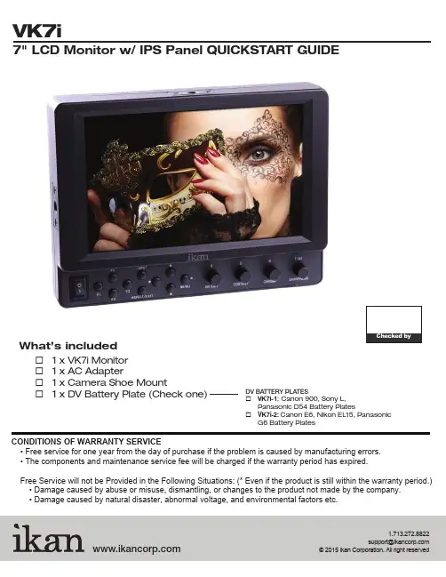
CONDITIONS OF WARRANTY SERVICE• Free service for one year from the day of purchase if the problem is caused by manufacturing errors. • The components and maintenance service fee will be charged if the warranty period has expired.Free Service will not be Provided in the Following Situations: (* Even if the product is still within the warranty period.) • Damage caused by abuse or misuse, dismantling, or changes to the product not made by the company. • Damage caused by natural disaster, abnormal voltage, and environmental factors etc.1.713.272.8822********************What’s included☐ 1 x VK7i Monitor ☐ 1 x AC Adapter☐ 1 x Camera Shoe Mount☐ 1 x DV Battery Plate (Check one)DV BATTERY PLATES☐ VK7i-1: Canon 900, Sony L, Panasonic D54 Battery Plates☐ V K7i-2: Canon E6, Nikon EL15, PanasonicG6 Battery PlatesVK7i1281211109131415Power SwitchPower ON / OFFPower Indicator Light When the power is ON, the LED green lights up Button T oggle left in MENU setting modeand ButtonsT oggle up and down in MENU setting mode / MENU ButtonT oggle right in MENU setting modeIn MENU, push button to select menu setting BRIGHT/R KnobAdjust brightness 0 - 100 (50)Adjust red channel CONTRAST/G KnobAdjust contrast 0 - 100 (50)Adjust green channel CHROMA/B KnobAdjust chroma 0 - 100 (50)Adjust blue channelTINT/SHARPNESS KnobAdjust tint 0 - 100 (50)Adjust sharpness 0 - 100 (10)TALL Y Indicator Lights1TALL Y Indicator LightsVIDEO terminal (BNC)IN : Composite signal input terminal OUT : Input signal through-out terminal YPbPr terminal (BNC)IN : Component signal input terminal OUT : : Input signal through-out terminal HDMI terminalIN : HDMI input terminalOUT : : Input signal through-out terminal DC 12V-24V power terminal XLR DC Connection TALL Y Input Connector RJ45 Connection DC 7-24V power terminal Standard DC ConnectionVESA 100mm Mount HolesThreaded for M3x.07 screws. Use to attach pro battery plate adapter or for mounting third party vesa mounts. USB terminalFor factory service use only¼-20 Threaded insert (on three sides of monitor) Mounting MonitorDV Battery Plate SlotMounting ikan DV battery plate234568791110++TALLYThe MANUAL function allows you to change the values of Red, Green, and Blue (RGB).This function recalls user de ned values settings .The user setting will remain in memory inde nitely and can be erased by using the reset option in the main menu.The DSLR Scaling function will allow users to extend their DSLR camera’s HDMI video output any option of four – Normal, 3:2, 16:9 or Full Screen – convenience made simple.This function displays the blanking portion of the incoming signal.The LCD panel in this display has a native display of 1280 x 800 pixels. A signal of any other resolution is scaled to t this native resolution. There may be time when it is desired to view the incoming signal without scaling. Enabling Pixel to Pixel mode turns off the scaling and displays a 1024x600 pixel window of the original image. Each pixel of the panel displays one pixel of the original image. The user may use the arrow buttons(buttons 3-6) on the monitor face to move the window left, right, up and down to see thedesired portion of the image. The VK7i is equipped with Monochrome Peaking features which highlight the desired focus area in a bright, red outline. The operator adjusts the focus control until the red indicator outlines on the desired area are razor sharp, indicating optimal focus. For the best results, be sure the subject is properly exposed.The False Color feature utilizes a full spectrum of assigned color indicators, ensuring awless shot exposure. As the camera Iris is adjusted, the subject of the image will change color based on speci c brightness values indicating optimal exposure. See included chart for color assignments.As an additional tool associated with the VK7i’s False Color feature, ikan’s exclusive Adjustable Under Exposure and Over Exposed Waning feature gives the operator full control of the VK7i False Color brightness values. By setting the preferred IRE exposure limits, the operator is warned when the image exposure is exceeding or falling under the preset IRE limit, providing customizable, full image exposure control.The VK7i offers adjustable upper Clip Guide levels to accurately display overexposed images in any shooting condition. The operator simply assigns the upper IRE to their preference and any exposure over the set IRE limit will ash in a vivid purple, indicatingonly the over exposed area.This function displays a side by side comparison of the incoming video signal. Pushing the F1/2 button one time will enter the mode. Each time the F1/2 button is pushed it will freeze the current frame on the right hand side of the display while the left continues to display the live signal. Pressing the exit button will exit the window mode. Use Window 1 for 16:9 signals and Window 2 for 4:3 signals. Display a crosshair on the center of screen.Brightness 0-100Contrast 0-100Chroma 0-100Sharpness 0-100Tint 0-100Color T emp. 5600 K6500 K9300 K MANUAL OSD Language English Chinese OSD Duration5-60 secondLuma Under Warn Luma Over WarnFuction 1 Window 1Window 2 HV DelayGuidesPeakingFalse Color Clip Guide Underscan DSLR Scaling Check Field Pixel Fuction 2 Window 1 Window 2 HV DelayGuidesPeakingFalse Color Clip Guide UnderscanDSLR Scaling Check Field Pixel Menu SetupUser 1-5System ResetCONFIGURATION OF SETTING MENUSCrosshairCrosshairFEATURES• 1280 x 800 resolution• Looping HDMI, Component, and Composite I/O• False Color - Adjustable Under Luminance & Over Luminance Warning• Clip Guide - Adjustable Threshold• Peaking Red outline• Under scan• Color T emperature Presets (9300K/6500K/5600K)• Guides (4: 3 & 16:9 Framing Safe Area)• Check Field (Blue gun, red, green, mono)• Side-By-Side Freeze Frame• H/V Delay• Aspect Ratio (FULL / 16: 9 / 4: 3)• 5 user-de ned group• RGB Adjust• Resolution support - 480i/p ; 576i/p ; 720p24hz 25hz 30hz 50hz 60hz 24hzsf 25hzsf; 1080i/p 24hz 25hz 30hz 50hz 60hz 24hzsf 25hzsf • T ally system• DSLR scaling• Moveable pixel-to-pixelSPECIFICATIONSScreen Size: Diagonal 7" LCDResolution: 1280 x 800LCD Brightness: 400 NITViewing angles: 170(H) 170 (V)Operating Volts: DC 7 to 24VPower Consumption: 7 WattVideo Inputs: HDMI, Component, CompositeVideo Outputs: HDMI, Component, CompositeDimension: 5.6"H x 7.3"W x 1.6"DWeight: 18 lbs。

AT070TN92使用手册一、产品概述AT070TN92是一款7英寸的触摸屏显示器,具有高分辨率、高亮度、高对比度等特点,适用于各种商业和工业应用。
本手册将详细介绍AT070TN92的使用方法、功能和操作步骤。
二、快速启动指南1.连接电源:将AT070TN92的电源线连接到电源插座,并确保电源线连接牢固。
2.打开显示器:按下AT070TN92的电源按钮,等待显示器启动。
3.关闭显示器:按下AT070TN92的电源按钮,关闭显示器。
三、显示面板说明AT070TN92的显示面板采用高清LED背光,颜色逼真,视角广泛。
显示面板支持多点触控,可实现手势控制和多点操作。
四、按键功能介绍AT070TN92具有多个功能按键,包括电源按钮、音量调节按钮、菜单按钮等。
这些按键的功能如下:1.电源按钮:用于打开和关闭显示器。
2.音量调节按钮:用于调节扬声器的音量大小。
3.菜单按钮:用于进入菜单界面,进行各种设置和调整。
五、菜单操作指导AT070TN92的菜单界面采用图形化设计,用户可以通过触控或键盘进行操作。
菜单包括亮度、对比度、颜色等选项,可根据需要进行调整。
用户可根据实际需求选择相应菜单项,并进行参数设置和调整。
六、常见问题解答Q1:如何解决触摸屏失灵问题?A1:首先检查触摸屏是否清洁,如有污垢请用柔软的布擦拭干净;其次检查触摸屏是否正常工作,如有问题请联系专业维修人员进行检查和维修。
Q2:如何调整显示器的亮度?A2:在菜单界面中,选择“亮度”选项,通过滑动条或输入数值来调整亮度。
根据实际需要选择合适的亮度值,以获得更好的视觉效果。
Q3:触摸屏响应速度较慢或无法正确识别手势。
A3:请检查触摸屏是否清洁,如有污垢请用柔软的布擦拭干净。
如仍无法解决问题,可能是触摸屏出现故障,请联系专业维修人员进行检修。
七、性能参数列表AT070TN92的性能参数如下:1.尺寸:7英寸2.分辨率:800x480像素3.亮度:350cd/m²4.对比度:1500:15.视角:178°/178°(水平/垂直)6.响应时间:5ms7.触摸屏类型:电容式触摸屏8.颜色:16.7M色彩9.工作温度:0℃~40℃10.存储温度:-10℃~50℃11.工作湿度:10%~85%相对湿度(无冷凝)12.存储湿度:5%~95%相对湿度(无冷凝)13.电源要求:DC 12V/3A电源适配器(电池充电器)14.功率消耗:≤35W(正常工作),≤0.5W(待机/关机)八、安全注意事项1.请勿在潮湿的环境中使用AT070TN92,以免造成短路或设备损坏。
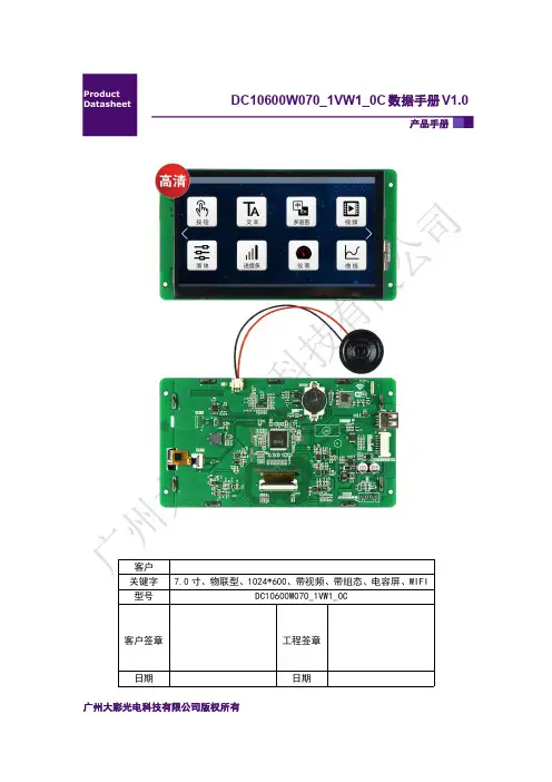
产品手册DC10600W070_1VW1_0C 数据手册V1.0广州大彩光电科技有限公司版权所有目录1.硬件介绍 (1)1.1硬件配置 (1)1.2调试工具 (1)2.产品规格 (2)3.可靠性测试 (4)4.产品尺寸 (5)5.产品定义 (6)6.产品架构 (7)7.开发软件 (8)7.1什么是虚拟串口屏 (8)7.2Keil与虚拟串口屏绑定调试 (9)8.开发文档 (10)1.硬件介绍以下主要介绍产品的一些硬件配置信息和调试所需工具。
1.1硬件配置以下为该产品硬件配置图,如图1-1所示。
图1-1硬件配置图1.2调试工具以下为该产品调试工具参考图,如图1-2所示。
图1-2调试工具图2.产品规格◆产品参数产品型号DC10600W070_1VW1_0C(电容触摸)产品系列物联型核心处理器*400MHz32位双核处理器操作系统嵌入式实时操作系统协议类型大彩组态指令集(部分可升级兼容MODBUS/三菱PLC/DGUS)尺寸7.0寸分辨率1024*600存储空间1Gbit字库内置矢量字体,边缘抗锯齿处理,包含任何大小点阵ASCII、GBK、GB2312、UNICODE 字库,可自定义任意电脑字体显示图片存储支持JPEG、PNG(半透/全透)压缩,支持任意大小图片存储,支持图片旋转、放大、缩小等功能。
累加可存储约611张全屏图片(按大小172KB/张计算,不建议BMP格式)。
图片压缩比不同,此值会上下浮动颜色65K色,16位RGB电压 4.5-15V(误差±0.2V)功耗背光最亮:3.5W;关背光:1.7W通讯接口RS232/TTL(出厂默认232电平)接口规格默认PH2.0-8P,可选配FPC1.0-10P图片下载U盘/UART/WIFI(U盘必须是FAT32格式,且从未做过电脑系统启动盘)外部键盘不支持实时时钟(RTC)支持倒计时、定时器、年月日等时间显示屏有效显示区(AA)长×宽=155.5mm×88.0mm产品尺寸长×宽×高=188.9mm×105.2mm×17.0mm配套上位机软件VisualTFT®AV输入不支持声音播放MP3音频格式(喇叭4Ω2W,单声道),与图片共用存储空间。
w w w.d a t a v i d e o.c o m7" TFT LCD MONITOR2Standard Warranty• Datavideo equipment is guaranteed against any manufacturing defects for one year from the date of purchase.• The original purchase invoice or other documentary evidence should be supplied at the time of any request for repair under warranty.• Damage caused by accident, misuse, unauthorized repairs, sand, grit or water is not covered by this warranty.• All mail or transportation costs including insurance are at the expense of the owner.• All other claims of any nature are not covered.• Cables & batteries are not covered under warranty.• Warranty only valid within the country or region of purchase.• Your statutory rights are not affected.Two Year Warranty• All Datavideo products purchased after 01-Oct.-2008 qualify for a free one year extension to the standard Warranty, providing the product is registered with Datavideo within 30 days of purchase. For information on how to register please visit or contact your local Datavideo office or authorized Distributors• Certain parts with limited lifetime expectancy such as LCD Panels, DVD Drives, Hard Drives are only covered for the first 10,000 hours, or 1 year (whichever comes first).• Any second year warranty claims must be made to your local Datavideo office or one of its authorized Distributors before the extended warranty expires.WarrantyWelcome to the TLM-700HD Instruction ManualThank you for choosing a Datavideo product, pleasevisit the support pages on our website for the latestversion of the instruction manual./LCD+Monitors/TLM-700HDDon’t forget to register your product online to qualify foran additional free one year extension to the standardwarranty, and to receive information from Datavideo onservice & information relevant to your Datavideo productincluding new software updates & driversTLM-700HD3Disclaimer of Product and Services The information offered in this instruction manual is intended as a guide only. At all times, Datavideo Technologies will try to give correct, complete and suitable information. However, Datavideo Technologies cannot exclude that some information in this manual, from time to time, may not be correct or may be incomplete. This manual may contain typing errors, omissions or incorrect information. Datavideo Technologies always recommend that you double check the information in this document for accuracy before making any purchase decision or using the product. Datavideo Technologies is not responsible for any omissions or errors, or for any subsequent loss or damage caused by using the information contained within this manual. Further advice on the content of this manual or on the product can be obtained by contacting your local Datavideo Office or dealer. ContentsWelcome to the TLM-700HD Instruction Manual 2Warranty 2Standard Warranty 2Two Year Warranty 2Disposal 4Warnings and Precautions 4Packing List 5Introduction 5Features 6Supported Formats 6Connections & Controls 7Front Panel 7Rear Panel 9Menu Options 101. Picture (Screen Setup) 10Picture setting 10Brightness 102. Audio (Audio Indicator) 103. Function (Center Mark, Safety Zone) 10Center Mark 10Safety Zone 104. Setup (On Screen Display, Time Code) 11OSD Timer 11OSD Blending 11Time Code 11TC Position 11TC HD Line 11TC SD Line 11TC Font Size 115. Advance (LCD Display, Reset Firmware Version) 12LCD L/R Scan 12LCD U/D Scan 12Reset 12Calibrating Datavideo Monitors 12Tally light indication 13TLM-700HD Model & Battery Plate Variations 14Specifications 15Service & Support 167" TFT LCD MONITOR4Warnings and Precautions1.Read all of these warnings and save them for later reference.2.Follow all warnings and instructions marked on this unit.3.Unplug this unit from the wall outlet before cleaning. Do not use liquid or aerosol cleaners. Use a slightly damp cloth for cleaning.4.Do not use this unit in or near water.5.Do not place this unit on an unstable surface, cart, stand, or table. The unit may fall, causing serious damage.6.Any slots and openings on the case top, back, and bottom are provided for ventilation. To ensure safe and reliable operation of this unit, and to protect it from overheating, do not block or cover these openings. Do not place this unit on a bed, sofa, rug, or similar surface, as the ventilation openings may become blocked. This unit should never be placed near or over a heat source or radiator. This unit should not be placed in a built-in installation unless proper ventilation is provided.7.This product should only be operated from the type of power source indicated on the marking label of the AC adapter. If you are not sure of the type of power available, consult your Datavideo dealer or your local power company.8.Do not allow anything to rest on the power cord. Do not locate this unit where the power cord will be walked on, rolled over, damaged or otherwise stressed.9.If an extension cord must be used with this unit, make sure that the total of the ampere ratings on the products plugged into the extension cord do not exceed the extension cord’s rating.10.Make sure that the total amperes of all the units that are plugged into asingle wall outlet do not exceed 15 amperes.11.Never push objects of any kind into this unit through the case ventilationslots, as they may touch dangerous voltage points or short out parts that could result in risk of fire or electric shock. Never spill liquid of any kind onto or into this unit.12.Except as specifically explained elsewhere in this manual, do not attemptFor EU Customers only - WEEE MarkingThis symbol on the product indicates that it will not be treatedas household waste. It must be handed over to the applicabletake back scheme for the recycling of electrical and electronicequipment. For more detailed information about the recycling ofthis product, please contact your local Datavideo office.DisposalTLM-700HD5Introductionto service this product yourself. Opening or removing covers that are marked “Do Not Remove” may expose you to dangerous voltage points or other risks, and will void your warranty. Refer all service issues to qualified service personnel.13.Unplug this product from the wall outlet and refer to qualified service personnel under the following conditions:a.When the power cord is damaged or frayed;b.When liquid has spilled into the unit;c.When the product has been exposed to rain or water;d.When the product does not operate normally under normal operating conditions. Adjust only those controls that are covered by the operating instructions in this manual; improper adjustment of other controls may result in damage to the unit and may often require extensive work by a qualified technician to restore the unit to normal operation;e.When the product has been dropped or the case has been damaged;f. When the product exhibits a distinct change in performance, indicating a need for service.The Datavideo TLM-700HD is a 7 Inch monitor designed for use in the field or in a studio. The TLM-700HD can be powered from a standard V-Mount battery connection or by mains power. It is rugged and easy to carry with a variety of professional features and connections that make it easy for set up and intuitive to use.7" TFT LCD MONITOR6FeaturesSupported Formats• 7" 16:9 Wide Screen Panel• Resolution: 800 x 480 dots• View Angle (V)+60/-40°, (H)+60/-60°• HD/SD-SDI, YUV, HD-YUV, HDMI & CV Input• Internal colour bar• Blue only function• Audio indicator for SDI, HDMI• Safe Area indicator• VITC time code display• Dual colour tally light indicator• Brightness, Contrast, Colour, Tint Adjustable• Colour T emp* adjustable• Audio Level indicators• NTSC / PAL Auto Switching• 4:3 / 15:9 / 16:9 switchable* can be set to 9300, 7500, 6500, 5400 or USER RGB values.■ HDMI YUV• 720 x 576i x 50 Hz• 720 x 480i x 60 Hz• 1280 x 720p x 50 Hz• 1280 x 720p x 60 Hz• 1920 x 1080i x 50 Hz• 1920 x 1080i x 60 Hz■ HDMI RGB• 720 x 576i x 50 Hz• 720 x 480i x 60 Hz• 1280 x 720p x 50 Hz• 1280 x 720p x 60 Hz• 1920 x 1080i x 50 Hz• 1920 x 1080i x 60 Hz■ SDI• 720 x 576i / 50 Hz• 720 x 480i / 60 Hz• 1280 x 720p / 60 Hz• 1280 x 720p / 50 Hz• 1920 x 1080i / 50 Hz• 1920 x 1080i / 60 Hz■ YUV• 720 x 576i x 50 Hz• 720 x 480i x 60 Hz• 1280 x 720p x 50 Hz• 1280 x 720p x 60 Hz• 1920 x 1080i x 50 Hz• 1920 x 1080i x 60 Hz■ CV• 720 x 576i (PAL)• 720 x 480i (NTSC)TLM-700HD7Front Panel Connections & ControlsPOWERON OFFSOURCEASPECT Power Switch Switches the power On / Off.Stereo Headphone Mini Jack socket The level is adjusted by headphone volume control.Listen to embedded audio from HDMI or SDI sources.Source Button Selects Input include SDI, YPbPr, CVBS, and HDMI.Aspect Ratio Button Select 4.3, 15:9, or 16:9PATTERN Generate on colour bars.7" TFT LCD MONITOR8BLUEFor blue only display to allow accurate chromaand phase adjustments with NTSC signals.MENUCalls up the on-screen adjustment menu (SeePage10 Menu Options for more details).UP / DOWNMenu navigation controls.ENTERConfirms the new settings or return to the defaultstate.TALLY LIGHTRed = LiveAmber = StandbyMENUENTERTLM-700HD9BNC connector for Analogue (Composite) videoinput.HDMI in interface Supports HDMI 1.1Tally In Sends in red and amber colour tally signal to tally LED. Red means on-air, amber means standby.DC in socket Connects the supplied 12V 1A PSU to this socket. The connection can be secured by screwing the outer fastening ring of the DC In plug to the socket.7" TFT LCD MONITOR10Menu Options1. Picture (Screen Setup)Picture setting■ Press the MENU button once to display the Picture setting menu.■ Press the ENTER button to highlight the Brightness setting.■ Press the UP or DOWN button to highlight the setting that needs to be adjusted.Brightness■ Press ENTER button to select the Brightness setting.■ Press the UP or DOWN button to adjust the Brightness value between 0 and 100.■ Press ENTER button again to save and return to the Picture setting menu;now highlight another Picture setting to be adjusted. To select a different setting (Contrast, Saturation, Tint, Color Temp*) use the UP / DOWN buttons. Follow the same procedure to set the other values.■ Keep pressing the MENU button to cycle through the main menu options.■ Press the SOURCE button to exit the menu mode.* N.B.: Color Temp can be set to 9300, 7500, 6500, 5400 or USER RGB values.2. Audio (Audio Indicator)■ Press the MENU button twice to display the Audio setting menu.■ Press the ENTER button to highlight the Indicator setting.■ Press the ENTER button again to toggle the on screen audio indicator ON/OFF.■ Keep pressing the MENU button to cycle through the main menu options.■ Press the SOURCE button to exit the menu mode.3. Function (Center Mark, Safety Zone)■ Press the MENU button three times to display the Function. Settings menu.Center Mark■ Press the ENTER button to highlight the Center Mark setting.■ Press the ENTER button to toggle the on screen Center Mark ON/OFF. Safety Zone■ Press the UP or DOWN button to highlight the Safety Zone setting.■ Keep pressing the ENTER button to cycle through the values 80%, 90% or OFF.■ Press the UP or DOWN button to exit the Safety Zone setting. To selecta different setting (4:3 Screen, Cinema Zone) use the UP or DOWNbuttons. Follow the same procedure to set the next setting.■ Keep pressing the MENU button to cycle through the main menu options.■ Press the SOURCE button to exit the menu mode.TLM-700HD114. Setup (On Screen Display, Time Code)■ Press the MENU button four times to display the Setup setting menu.OSD Timer■ Press the ENTER button to highlight the OSD Timer setting.* N.B.: OSD Timer sets how long the setting menus will stay on screen.■ Press the ENTER button again to display the OSD Timer setting position.■ Press the UP or DOWN button to set the OSD value between 5 to 60 SEC.■ Press ENTER button to save the OSD value.OSD Blending■ Press the UP or DOWN button to highlight the OSD Blending setting.* N.B.: OSD Blending sets how transparent the setting menus will be on screen.■ Press the ENTER button to display the OSD Blending setting position.■ Press the UP or DOWN button to select the OSD blending value (from 0~7).* N.B.: OSD Blending value 0 = Min transparency 7 = Max transparency ■ Press the ENTER button to save the OSD blending value. Time Code■ Press the UP or DOWN button to highlight the Time Code setting.■ Press the ENTER button to toggle the on screen Time Code display ON/OFF.TC Position■ Press the UP or DOWN button to highlight the TC Position setting.* N.B.: TC Position is used to set where on the monitor Time Code will be shown.■ Press the ENTER button to cycle through the possible Time Code Positions on the monitor (Left/Up, Middle/Down, Right/Down, Right/Up)TC HD Line■ Press the UP or DOWN button to highlight the TC HD Line setting.■ Press ENTER button to cycle through the possible HD time code lines (8~20).TC SD Line■ Press the UP or DOWN button to highlight the TC SD Line setting.■ Press ENTER button to cycle through the possible SD time code lines (10~21).TC Font Size■ Press the UP or DOWN button to highlight the TC Font Size setting.■ Press ENTER button to cycle through the possible time code font sizes on the screen (Large or Small).■ Keep pressing the MENU button to cycle through the main menu options.■ Press the SOURCE button to exit the menu mode.7" TFT LCD MONITOR12Calibrating Datavideo MonitorsCalibrating professional monitors is crucial.For guidance on how to calibrate a Datavideo Monitor using SMPTE colour bars please visit our website /specs/Datavideo_Calibrating_Monitors.pdf 5. Advance (LCD Display, Reset Firmware Version)■ Press the MENU button five times to display the Advance setting menu.LCD L/R Scan■ Press the ENTER button to highlight the LCD L/R Scan setting.* N.B.: The LCD L/R Scan will reverse the image displayed horizontally.■ Press the ENTER button, the screen image will be reversed (Left to Right).■ Press the ENTER button again, the screen image will return to normal view.LCD U/D Scan■ Press UP / DOWN button to highlight the LCD U/D Scan setting.* N.B.: The LCD U/D Scan will reverse the image displayed vertically.■ Press the ENTER button, the screen image will be reversed (Top to Bottom).■ Press the ENTER button again, the screen image will return to normal view.Reset■ Press UP / DOWN button to highlight the Reset option.* N.B.: This option will return the monitor to the factory default settings.■ Press the ENTER button to re-start the monitor with the factory default settings.Version■ Press UP / DOWN button to highlight the Version setting.■ Press the ENTER button, the firmware version will be displayed on screen.■ Keep pressing the MENU button to cycle through the main menu options.■ Press the SOURCE button to exit the menu mode.TLM-700HD13Tally light indicationThe TLM-700HD has a tally input connector on the rear panel; many digital video switchers can provide tally light signals to this connector. The Datavideo range of intercom systems can also be used to pass on thesetally signals.Tally InD-sub 15pin type connector.TALLY LIGHTRed = LiveAmber = Standby7" TFT LCD MONITOR14TLM-700HD Model & Battery Plate VariationsTLM-700HD:with V-mount Battery PlateTLM-700HD-C:with Canon battery mountTLM-700HD-P:with Panasonic battery mountTLM-700HD-S1 & -S2:with Sony battery mountTLM-700HD-A:with Anton Bauer battery mountThere are several versions ofTLM-700HD monitor with differentbattery connection plates.TLM-700HD Specifications15All the trademarks are the properties of their respective owners. Datavideo Technologies Co., Ltd. All rights reserved 2018Service & SupportJan-24.2014 P/N: G082060476E6It is our goal to make your products ownership a satisfying experience. Our supporting staff is available to assist you in setting up and operating your system. Please refer to our web site for answers to common questions, support requests or contact your local office below.R.O.C.U.S.A.Datavideo Technologies (S) PTE Ltd No. 178 Paya Lebar Road #06-03Singapore 409030Tel:+65-6749 6866Fax:+65-6749 3266E-mail:******************Datavideo United KingdomDatavideo SingaporeDatavideo UK LimitedUnits1 & 2 Waterside Business Park Hadfield, Glossop, Derbyshire SK13 1BE, UKTel:+44-1457 851 000Fax:+44-1457 850 964E-mail:******************.ukDatavideo IndiaDatavideo Technologies India Pvt Ltd Fax:+91-0120-2427338E-mail:******************Tel:+91-0120-2427337A-132, Sec-63,Noida-201307,Uttar Pradesh (UP), India.Datavideo Technologies Co. Ltd10F. No. 176, Jian 1st Rd.,Chung Ho District, New Taipei City 235, Taiwan, Tel: +886-2-8227-2888Fax: +886-2-8227-2777E-mail:*********************.twDatavideo Corporation 7048 Elmer Avenue.Whittier, CA 90602, Tel:+1-562-696 2324Fax:+1-562-698 6930E-mail:******************Datavideo USADatavideo TaiwanDatavideo Hong KongDatavideo Hong Kong Ltd G/F.,26 Cross Lane Wanchai, Hong Kong Tel: +852-2833-1981Fax: +852-2833-9916E-mail:******************.hkDatavideo Technologies Europe BV Floridadreef 1063565 AM Utrecht, The NetherlandsTel:+31-30-261-96-56Fax:+31-30-261-96-57E-mail:*****************Datavideo The NetherlandDatavideo ChinaDatavideo Technologies China Co101,NO.618,LiuYing Rd,Zhabei District,Shanghai,ChinaTel: +86 21-5603 6599Fax: +86 21-5603 6770E-mail:********************Datavideo FranceDatavideo France s.a.r.lCité Descartes 1,rue Albert Einstein Champs sur Marne774477-Marne la Vallée cedex 2Tel:+33-1-60370246E-mail:*****************。
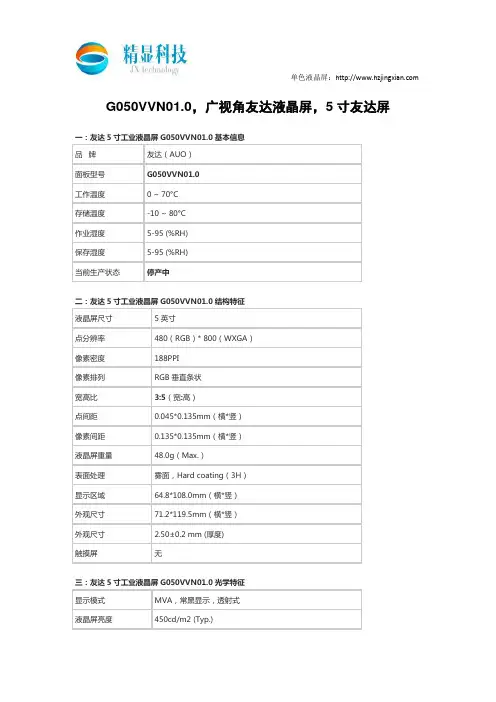
INNOLUX DISPLAY CORPORATIONLCD MODULESPECIFICATIONCustomer:Model Name: NJ070NA-23ADate: 2017/02/27Version: 01□Preliminary Specification■Final SpecificationFor Customer’s AcceptanceApproved by CommentApproved by Reviewed by Prepared byCs.Chang Henry.Chien 2016/12/27 Cc01.ChenWenguo.DengSunny.Sun2016/12/27Rong.Ye2016/12/27InnoLux copyright 2016All rights reserved,Copying forbidden.Record of RevisionVersion Revise Date Page ContentPre-Spec.V01 2014/04/15 All Initial Release.Pre-Spec.V02 2014/12/23 1 Update Backlight power consumption& Panel power consumption& Weight5 Update Operation Specifications6 Update Input signal voltage7 Update Current Consumption& Backlight Driving Conditions13 Update Optical Specifications20 Update Packaging Material TablePre-Spec.V03 2015/01/09 7 Update Current Consumption18 Update Safety19 Modify Mechanical Drawing21 Modify Package DrawingFinal-Spec 2015/04/20 First Final Release for P070BAG-CM119 Modify Mechanical Drawing2016/01/07 19 Modify Mechanical Pixel size.Final-Spec-V01 2016/12/271 Model name change from P070BAG-CM1 to NJ070NA-23AFinal-Spec-V02 2017/02/27 20 Modify Reliability Test ItemINNO L U XContents1. General Specifications (1)2. Pin Assignment (2)3. Operation Specifications (5)3.1. Absolute Maximum Ratings (5)3.1.1. Typical Operation Conditions (6)3.1.2. Current Consumption (7)3.1.3. Backlight Driving Conditions (7)3.2. Power Sequence (8)3.3. Timing Characteristics (9)3.3.1. AC Electrical Characteristics (9)3.3.2. Input Clock and Data Timing Diagram (9)3.3.3. DC Electrical Characteristics (10)3.3.4. Timing (11)3.3.5. Data Input Format (12)4. Optical Specifications (13)5. Reliability Test Items (17)6. General Precautions (18)6.1. Safety (18)6.2. Handling (18)6.3. Static Electricity (18)6.4. Storage (18)6.5. Cleaning (18)7. Mechanical Drawing (19)8. Package Drawing (20)8.1. Packaging Material Table (20)8.2. Packaging Quantity (20)8.3. Packaging Drawing (21)1. General SpecificationsThe specification NJ070NA-23A is a 7 ”(1024x600) TFT Liquid Crystal Display module with LED Backlight unit , 40 pin LVDS interface, normally white transmissive display mode. This module will be applied to Consumer Electronics(CE Application)No. Item Specification Remark1 LCD size 7.0 inch(Diagonal)2 Driver element a-Si TFT active matrix3 Resolution 1024 × 3(RGB) × 6004 Display mode Normally White, Transmissive5 Pixel size 0.1506(W) × 0.1432(H) mm6 Active area 154.2144(W) × 85.92(H) mm7 Module size 164.9(W) ×100(H) ×4.8(D) mm Note 18 Surface treatment Hard Coating9 Color arrangement RGB-stripe10 Interface LVDS11 View direction(Gray Inversion) 6 O’Clock12 Backlight power consumption 2.62 W (Typ.)13 Panel power consumption 0.4 W (Typ.)14 Weight 140g (Typ.)15 Source Driver IC NT51008QH-D/3EA16 Gate Driver IC NT52003BH-D/3EBNote 1: Refer to Mechanical Drawing.2. Pin AssignmentFPC Connector is used for the module electronics interface. The recommended model is FH12A-40S-0.5SH manufactured by Hirose.Pin No. Symbol I/O Function Remark1 VCOM P Common Voltage2 VDD P Power Voltage for digital circuit3 VDD P Power Voltage for digital circuit4 NC --- No connection5 Reset I Global reset pin6 STBYB I Standby mode, Normally pulled high STBYB = “1”, normal operation STBYB = “0”, timing controller, source driver will turn off, all output are High-Z7 GND P Ground8 RXIN0- I - LVDS differential data input9 RXIN0+ I + LVDS differential data input10 GND P Ground11 RXIN1- I - LVDS differential data input12 RXIN1+ I + LVDS differential data input13 GND P Ground14 RXIN2- I - LVDS differential data input15 RXIN2+ I + LVDS differential data input16 GND P Ground17 RXCLKIN- I - LVDS differential clock input18 RXCLKIN+ I + LVDS differential clock input19 GND P Ground20 RXIN3- I - LVDS differential data input21 RXIN3+ I + LVDS differential data input22 GND P Ground23 NC --- No connection24 NC --- No connection25 GND P Ground26 NC --- No connection27 DIMO O Backlight CABC controller signal output28 SELB I 6bit/8bit mode select Note129 AVDD P Power for Analog Circuit30 GND P Ground31 LED- P LED Cathode32 LED- P LED Cathode33 L/R I Horizontal inversion Note334 U/D I Vertical inversion Note335 VGL P Gate OFF Voltage36 CABCEN1 I CABC H/W enable Note237 CABCEN0 I CABC H/W enable Note238 VGH P Gate ON Voltage39 LED+ P LED Anode40 LED+ P LED AnodeI: input, O: output, P: PowerNote1: If LVDS input data is 6 bits ,SELB must be set to High;If LVDS input data is 8 bits ,SELB must be set to Low.Note2: When CABC_EN=”00”, CABC OFF.When CABC_EN=”01”, user interface image.When CABC_EN=”10”, still picture.When CABC_EN=”11”, moving image.When CABC off, don’t connect DIMO, else connect it to backlight. Note3: When L/R=”0”, set right to left scan direction.When L/R=”1”, set left to right scan direction.When U/D=”0”, set top to bottom scan direction.When U/D=”1”, set bottom to top scan direction.Note: Definition of scanning direction. Refer to the figure as below:LeftTOPRightBottom3. Operation Specifications3.1. Absolute Maximum Ratings(Note 1)Item SymbolValuesUnit Remark Min. Max.Power voltageDV DD -0.3 5.0 V AV DD 6.5 13.5 V V GH -0.3 42.0 V V GL -20.0 0.3 V V GH-V GL- 40.0 VOperation T emperature T OP -20 70 ℃Storage T emperature T ST-30 80 ℃LED Reverse Voltage V R- 5 VEach LED LED Forward Current I F- 60 mA Each LEDNote 1: The absolute maximum rating values of this product are not allowed to be exceeded at any times. Should a module be used with any of the absolute maximum ratingsexceeded, the characteristics of the module may not be recovered, or in an extremecase, the module may be permanently destroyed.3.1.1. Typical Operation Conditions( Note 1)ItemSymbolValuesUnitRemarkMin.Typ. Max. Power voltageDV DD 3.0 3.3 3.6 V Note 2 AV DD10.81111.2VV GH 19.7 20 20.3 V V GL-6.5 -6.8 -7.1 V Input signal voltage V COM 3.3 3.8 4.3 V Note 4Input logic high voltage V IH 0.7 DV DD- DV DD VNote 3Input logic low voltageV IL-0.3 DV DDVNote 1: Be sure to apply DV DD and V GL to the LCD first, and then apply V GH .Note 2: DV DD setting should match the signals output voltage (refer to Note 3) ofcustomer’s system board.Note 3: LVDS, Reset.Note 4: Typ. V COM is only a reference value, it must be optimized according to each LCM.Be sure to use VR;3.1.2. Current ConsumptionItem SymbolValuesUnit Remark Min. Typ. Max.Current for DriverI GH - 0.26 1 mA V GH =20V I GL - 0.26 1 mA V GL = -6.8V IDV DD - 35 60 mA DV DD =3.3V IAV DD - 20 30 mA AV DD =11V3.1.3. Backlight Driving ConditionsItem SymbolValuesUnit Remark Min. Typ. Max.Voltage for LED backlight V L 8.4 9.9 10.2 V Note 1 Current for LED backlight I L -- 265 -- mALED life time - 20,000 - - Hr Note 2 Note 1: The LED Supply Voltage is defined by the number of LED at Ta=25℃ andI L =265mA.Note 2: The “LED life time” is defined as the module brightness decrease to 50% original brightness at Ta=25℃ and I L =265mA. The LED lifetime could be decreased ifoperating I L is lager than 265mA.3.2. Power Sequencea. Power on:VDD A VGL VGH LVDS Signal B/L VDD A VGL VGH LVDS SignalB/L3.3. Timing Characteristics3.3.1. AC Electrical CharacteristicsParameter SymbolValuesUnit Remark Min. Typ. Max.Clock frequency R xFCLK40.8 51.2 67.2 MHz Input data skew margin T RSKM500 - - ps Clock high time T LVCH- 4/(7* R xFCLK) - ns Clock low time T LVCL- 3/(7* R xFCLK) - ns3.3.2. Input Clock and Data Timing Diagram3.3.3. DC Electrical CharacteristicsParameter SymbolValuesUnit Remark Min. Typ. Max.Differential input high Threshold voltage R xVTH- - +0.1 VR XVCM=1.2VDifferential input lowThreshold voltageR xVTL-0.1 - - V Input voltage range(singled-end)R xVIN0 - 2.4 V Differential input common modevoltageR xVCM|V ID|/2 - 2.4-|V ID|/2 V Differential voltage|V ID|0.2 - 0.6 V Differential input leakage current RV xliz-10 - +10 uA3.3.4. TimingItem SymbolValuesUnit Remark Min. Typ. Max.Clock Frequency fclk 40.8 51.2 67.2 MHz Frame rate =60HzHorizontal display area thd1024 DCLK HS period time th1114 1344 1400 DCLK HS Blanking thb90 320 376 DCLK Vertical display area tvd600 H VS period time tv610 635 800 H VS Blanking thb10 35 200 H3.3.5. Data Input Format6bit LVDS input8bit LVDS inputNote: Support DE timing mode only, SYNC mode not supported.4. Optical SpecificationsItem Symbol ConditionValuesUnit Remark Min. Typ. Max.Viewing angle (CR≥ 10) θLΦ=180°(9 o’clock)65 75 -degree Note 1 θRΦ=0°(3 o’clock) 65 75 -θTΦ=90°(12 o’clock)60 70 -θBΦ=270°(6 o’clock)65 75 -Response timeT ONNormalθ=Φ=0°- 10 20 msec Note 3T OFF - 15 30 msec Note 3 Contrast ratio CR 500 800 - - Note 4Color chromaticity W X 0.26 0.31 0.36 - Note 2Note 5Note 6 W Y 0.28 0.33 0.38 -Luminance L 400 500 - cd/m² Note 6 LuminanceuniformityY U 70 75 - % Note 7Test Conditions:1. DV DD=3.1V, I L=265mA (Backlight current), the ambient temperature is 25℃.2. The test systems refer to Note 2.Fig. 4-1 Definition of viewing angleNote 2: Definition of optical measurement system.The optical characteristics should be measured in dark room. After 30 minutesoperation, the optical properties are measured at the center point of the LCD screen. (Response time is measured by Photo detector TOPCON BM-7, otheritems are measured by BM-5A/Field of view: 1° /Heig ht: 500mm.)Fig. 4-2 Optical measurement system setup6 o’clock directionΦ=0°Φ=180°6 o’clock direction Φ=0°Φ=180°LCMNote 3: Definition of Response timeThe response time is defined as the LCD optical switching time interval between“White” state and “Black” state. Rise time (T ON ) is the time between photo detector output intensity changed from 90% to 10%. And fall time (T OFF ) is the time between photo detector output intensity changed from 10% to 90%.Fig. 4-3 Definition of response timeNote 4: Definition of contrast ratiostate Black"" the on LCD when measured Luminance stateWhite"" the on LCD when measured Luminance (CR) ratio Contrast =Contrast ratio is measured at center point of LCD.Note 5: Definition of color chromaticity (CIE1931)Color coordinates measured at center point of LCD.Note 6: Definition of luminance:Measured at the center area of the panel when LCD panel is driven at “white ” state. The LED driving condition is I L =265mA .90%10% 0%P h o t o d e t e c t o r o u t p u t (R e l a t i v e v a l u e )ONWhite (TFT OFF)Black (TFT ON)White (TFT OFF)Note 7: Definition of Luminance UniformityActive area is divided into 9 measuring areas (Refer to Fig. 4-4 ).Every measuring point is placed at the center of each measuring area.max minB B (Yu)Uniformity Luminance =L-------Active area length W----- Active area widthFig. 4-4 Definition of measuring pointsB max : The measured maximum luminance of all measurement position. B min : The measured minimum luminance of all measurement position.5. Reliability Test ItemsItem Test Conditions Remark High Temperature Storage Ta = 80℃240hrs Note 1,Note3,Note 4,Note5Low Temperature Storage Ta = -30℃240hrs Note 1,Note3,Note 4High Temperature Operation Ts = 70℃240hrs Note 2,Note3,Note 4,Note5Low Temperature Operation Ta = -20℃240hrs Note 1,Note3,Note 4Operate at High Temperature and Humidity +60℃, 90%RH 240hrsNote3,Note 4Note5Thermal Shock [(-30℃30min)→(80℃30min)]/cycle,100cyclesNote3,Note 4Note5Vibration Test Frequency: 10 ~55~10Hz; Sweep Mode: Log SweepSweep time: 1Oct/min; Acceleration: 1.5G; Test time: 2hrs for each direction of X, Y, Z.Mechanical Shock 100G, 6ms, half sine wave, 3 times for each direction of ±X, ±Y, ±ZPackage Vibration Test Random Vibration :ISTA-3A 1Hz~200Hz,Grms=0.53 Half hours for direction of ZPackage Drop Test 72cm(weight≦10kg), 60cm(weight>10kg);1 times for 6-faces, 3-edges and 1-cornerElectro Static Discharge Contact mode:150pf,330Ω,±2KV Air mode:150pf,330Ω,±2KVNote 1: Ta is the ambient temperature of samples.Note 2: Ts is the temperature of panel’s surface.Note 3: In the standard condition, there shall be no practical problem that may affect the display function. After the reliability test, the product only guarantees operation,but don’t guarantee all of the cosmetic specification.Note 4: Before cosmetic and function test, the product must have enough recovery time, at least 2 hours at room temperature.Note 5: A certain level of Mura (non-uniformity) of dark / black image will happen several days after high temperature testing (H.T.T.). There is a slowly part recovery over a long time (several months). Such a long exposure time like in H.T.T. will normally not happen in a real application. Therefore the test H.T.T. was introduced tosimulate cycles with normal conditions in-between but with the same totalexposure time what show a significant reduced Mura.The root cause is related to tension generated due to different amount of shrinking in thestack of layers in the polarizer sheet. The effect is more significant on larger displays likethis size. An investigation into alternative polarizer material showed that there is no better alternative currently available.6. General Precautions6.1. Safety1.Liquid crystal is poisonous. Do not put it in your mouth. If liquid crystal touches yourskin or clothes, wash it off immediately by using soap and water.2.The temperature for use is no more than 80 C, otherwise, only promise the functionis OK, but the quality may be changed.6.2. Handling1. The LCD panel is plate glass. Do not subject the panel to mechanical shock or toexcessive force on its surface.2. The polarizer attached to the display is easily damaged. Please handle it carefullyto avoid scratch or other damages.3. To avoid contamination on the display surface, do not touch the module surfacewith bare hands.4. Keep a space so that the LCD panels do not touch other components.5. Put cover board such as acrylic board on the surface of LCD panel to protect panelfrom damages.6. Transparent electrodes may be disconnected if you use the LCD panel underenvironmental conditions where the condensation of dew occurs.7. Do not leave module in direct sunlight to avoid malfunction of the ICs.6.3. Static Electricity1. Be sure to ground module before turning on power or operating module.2. Do not apply voltage which exceeds the absolute maximum rating value.6.4. Storage1. Store the module in a dark room where must keep at 25±10℃ and 65%RH or less.2. Do not store the module in surroundings containing organic solvent or corrosivegas.3. Store the module in an anti-electrostatic container or bag.6.5. Cleaning1. Do not wipe the polarizer with dry cloth. It might cause scratch.2. Only use a soft sloth with IPA to wipe the polarizer, other chemicals mightpermanent damage to the polarizer.7. M echanical Drawing8. Package Drawing8.1. Packaging Material TableNo. ItemModel(Material)Dimensions(mm)UnitWeight(kg)Quantity(PCS)Remark1 LCM NJ070NA-23A164.90x100x4.8 0.140 502 Dust-Proof BagPE 700 x 530x0.05 0.048 13 CrepePaper_Tape四維CM35 30x10x0.1 0.001 504 CorrugatedBarBC Corrugatedpaper510x122 0.046 45 Partition BC Corrugatedpaper512 × 349 × 226 1.466 16 A/S Bag PE 178*160*0.06 0.004 507 Carton Corrugatedpaper525 × 362 × 250 0.950 18 Total weight 10.12± 5%Kg8.2. Packaging QuantityTotal LCM quantity in Carton: no. of Partition 2 Rows × quantity per Row 25 = 508.3. Packaging Drawing。
Vision™ HMI+PLC Technical SpecificationsV700-T20BJOrdering InformationV700-T20BJ PLC with Flat panel, Color touch display 7’’You can find additional information, such as wiring diagrams, in the product’s installation guide located in the Technical Library at .Power SupplyInput voltage12 or 24VDCPermissible range10.2-28.8VDCMax. current consumption630mA@12V320mA@24VGraphic Display Screen See Note 1LCD Type TFT, LCD displayIllumination backlight White LEDDisplay resolution 800x480 pixelsViewing area 7"Colors 65,536 (16-bit)Touchscreen Resistive, analog‘Touch’ indication Via buzzerScreen brightness control Via software (Store value to SI 9, values range: 0 to 100%)Virtual Keypad Displays virtual keyboard when the application requires data entry. Notes:1. Note that the LCD screen may have a single pixel that is permanently either black or white.ProgramMemory size Application Logic – 2MB, Images – 60MB, Fonts – 1MBOperand type Quantity Symbol ValueMemory Bits 8192 MB Bit (coil)Memory Integers 4096 MI 16-bitLong Integers 512 ML 32-bitDouble Word 256 DW 32-bit unsignedMemory Floats 64 MF 32-bitFast Bits 1024 XB Bits (coil) – fast, not retainedFast Integers 512 XI 16 bit - fast, not retainedFast Long Integers 256 XL 32 bit - fast, not retainedFast Double Word 64 XDW 32 bit unsigned - fast, not retainedTimers 384 T Res. 10 ms; max 99h, 59 min, 59.99sCounters 32 C 16-bitData Tables 120K dynamic RAM data (recipe parameters, datalogs, etc.)Up tp 256K Flash data (read-only data, ingredient names, etc)Expandable via micro-SD card. See Removable Memory belowHMI displays Up to 1024Program scan time 9 µsec per 1K of typical application18/15 Vision™ HMI+PLC , V700-T20BJRemovable MemoryMicro-SD card Compatible with fast micro-SD cards; store datalogs, Alarms,Trends, Data Tables, backup Ladder, HMI, and OS. See Note 2 Notes:2. User must format via Unitronics SD tools utility.CommunicationPort 1 1 channel, RS232/RS485 and USB device. See Note 3 Galvanic isolation YesBaud rate range 300 to 115200 bpsRS232Voltage limits ±20VDC absolute maximumCable length Up to 15m (50’)RS485Voltage limits −7 to +12VDC differential maximumNodes Up to 32Cable type Shielded twisted pair, in compliance with EIA RS485Cable length 1200m maximum (4000’)USB See Note 4Port type Mini-BGalvanic isolation NoSpecification USB 2.0 compliant; full speedCable USB 2.0 compliant; up to 3mEthernetPort type RJ45Transmission speed 10/100MbpsNetwork topology Star, based on external hub/switchCable type Category 5 STP (shielded twisted pair) is recommended;UTP (unshielded twisted pair) may also be usedDrop line length Up to 100 meters, controller to hub/switch or controller to controller. Port 2 (optional) See Note 5CANbus (optional) See Note 5Notes:3. This model is supplied with a serial port: RS232/RS485 (Port 1). The standard is set to eitherRS232 or RS485 according to DIP switch settings. Refer to the product’s Installation Guide.4. Note that physically connecting a PC to the controller via USB suspends RS232/RS485communications via Port 1. When the PC is disconnected, RS232/RS485 resumes.5.The user may order and install one or both of the following modules:- A serial RS232/RS485 isolated/non-isolated interface module in port 2.- A CANbus moduleModules documentation is available on the Unitronics website.2Technical Specifications 8/15I/OsAdditional I/Os may be added. Configurations vary according tomodule. Supports digital, high-speed, analog, weight and temperaturemeasurement I/Os.Snap-in I/O modules Plugs into rear port to create self-contained PLC with up to 62 I/Os.I/O ExpansionLocal Via I/O Expansion Port. Integrate up to 8 I/O Expansion Modulescomprising up to 128 additional I/Os. Adapter required (P.N. EX-A2X).Remote Via CANbus port. Connect up to 60 adapters to a distance of 1000meters from controller; and up to 8 I/O expansion modules to eachadapter (up to a total of 512 I/Os). Adapter required (P.N. EX-RC1).Galvanic isolation YesMiscellaneousClock (RTC) Real-time clock functions (date and time)Battery back-up 7 years typical at 25°C, battery back-up for RTC and system data,including variable dataBattery replacement Yes (without opening the controller).Coin-type 3V, lithium battery, CR2450DimensionsSize 210 x 146.4 x 42.3mm (8.26 x 5.76 x 1.66”). See Note 6Weight 640g (22.57 oz)Notes:6. For exact dimensions, refer to the product’s Installation Guide.EnvironmentOperational temperature 0 to 50ºC (32 to 122ºF)Storage temperature -20 to 60ºC (-4 to 140ºF)Relative Humidity (RH) 10% to 95% (non-condensing)Mounting method Panel mounted (IP65/66/NEMA4X)Operating Altitude 2000m (6562 ft)Shock IEC 60068-2-27, 15G, 11ms durationVibration IEC 60068-2-6, 5Hz to 8.4Hz, 3.5mm constant amplitude,8.4Hz to 150Hz, 1G acceleration.The information in this document reflects products at the date of printing. Unitronics reserves the right, subject to all applicable laws, at any time, at its sole discretion, and without notice, to discontinue or change the features, designs, materials and other specifications of its products, and to either permanently or temporarily withdraw any of the forgoing from the market.All information in this document is provided "as is" without warranty of any kind, either expressed or implied, including but not limited to any implied warranties of merchantability, fitness for a particular purpose, or non-infringement. Unitronics assumes no responsibility for errors or omissions in the information presented inthis document. In no event shall Unitronics be liable for any special, incidental, indirect or consequential damages of any kind, or any damages whatsoever arisingout of or in connection with the use or performance of this information.The tradenames, trademarks, logos and service marks presented in this document, including their design, are the property of Unitronics (1989) (R"G) Ltd. or other third parties and you are not permitted to use them without the prior written consent of Unitronics or such third party as may own them.08/153。
( V ) Preliminary Specifications( ) Final SpecificationsModule 10.4 Inch Color TFT-LCD Model Name G104VN01 V1Customer DateChecked &Approved byNote: This Specification is subject to changewithout notice. Approved by Date Debbie Chiu2009/02/11 Prepared byVivian Huang 2009/02/11 General Display Business Division / AU Optronics corporationContents1. Operating Precautions (4)2. General Description (5)2.1 Display Characteristics (5)2.2 Optical Characteristics (6)3. Functional Block Diagram (9)4. Absolute Maximum Ratings (10)4.1 Absolute Ratings of TFT LCD Module (10)4.2 Absolute Ratings of Environment (10)5. Electrical Characteristics (11)5.1 TFT LCD Module (11)5.2 Backlight Unit (13)6. Signal Characteristics (14)6.1 Pixel Format Image (14)6.2 Scanning Direction (14)6.3 TFT-LCD Interface Signal Description (15)6.4 The Input Data Format (16)6.5 TFT-LCD Interface Timing (17)6.6 Power ON/OFF Sequence (18)7. Connector & Pin Assignment (19)7.1 TFT-LCD Signal (CN1): LCD Connector (19)7.2 LED Backlight Unit (CN2): Backlight Connector (19)8. Reliability Test Criteria (20)9. Mechanical Characteristics (21)9.1 LCM Outline Dimension (Front View) (21)9.2 LCM Outline Dimension (Rear View) (22)10. Label and Packaging (23)10.1 Shipping Label (on the rear side of TFT-LCD display) (23)10.2 Carton Package (23)11 Safety (24)11.1 Sharp Edge Requirements (24)11.2 Materials (24)11.3 Capacitors (24)11.4 National Test Lab Requirement (24)Version and Date Page Old description New Description0.0 2009/02/03All First Edition1. Operating Precautions1) Since front polarizer is easily damaged, please be cautious and not to scratch it.2) Be sure to turn off power supply when inserting or disconnecting from input connector.3) Wipe off water drop immediately. Long contact with water may cause discoloration orspots.4) When the panel surface is soiled, wipe it with absorbent cotton or soft cloth.5) Since the panel is made of glass, it may be broken or cracked if dropped or bumped onhard surface.6) To avoid ESD (Electro Static Discharde) damage, be sure to ground yourself before handlingTFT-LCD Module.7) Do not open nor modify the module assembly.8) Do not press the reflector sheet at the back of the module to any direction.9) In case if a module has to be put back into the packing container slot after it was takenout from the container, do not press the center of the LED light bar edge. Instead, press at the far ends of the LED light bar edge softly. Otherwise the TFT Module may be damaged.10) At the insertion or removal of the Signal Interface Connector, be sure not to rotate nortilt the Interface Connector of the TFT Module.11) TFT-LCD Module is not allowed to be twisted & bent even force is added on module in avery short time. Please design your display product well to avoid external force applying to module by end-user directly.12) Small amount of materials without flammability grade are used in the TFT-LCD module. TheTFT-LCD module should be supplied by power complied with requirements of Limited Power Source (IEC60950 or UL1950), or be applied exemption.13) Severe temperature condition may result in different luminance, response time and lampignition voltage.14) Continuous operating TFT-LCD display under low temperature environment may acceleratelamp exhaustion and reduce luminance dramatically.15) The data on this specification sheet is applicable when LCD module is placed in landscapeposition.16) Continuous displaying fixed pattern may induce image sticking. It’s recommended to usescreen saver or shuffle content periodically if fixed pattern is displayed on the screen.2. General DescriptionThis specification applies to the Color Active Matrix Liquid Crystal Display G104VN01 V1composed of a TFT-LCD display, a driver and power supply circuit, and a LED backlight system. The screen format is intended to support VGA (640(H) x 480(V)) screen and 16.2M (RGB 8-bits) or 262k colors (RGB 6-bits).LED driving board for backlight unit is included in G104VN01 V1 and the LED unit is replaceable.All input signals are LVDS interface and compatible with G104SN02 V1.G104VN01 V1 designed with wide viewing angle; wide temperature and long life LED backlight is well suited for industial applications. G104VN01 V1 is a RoHS product.2.1 Display CharacteristicsThe following items are characteristics summary on the table under 25 ℃ condition: ItemsUnitSpecifications Screen Diagonal [inch] 10.4Active Area [mm] 211.2 (H) x 158.4 (V) Pixels H x V 640 x 3(RGB) x 480 Pixel Pitch [mm] 0.33 x 0.33Pixel Arrangement R.G.B. Vertical Stripe Display ModeTN, Normally White Nominal Input Voltage VDD [Volt] 3.3 (typ.) Typical Power Consumption [Watt] 5.4WAll black pattern Weight [Grams] 390 (typ.)Physical Size [mm] 243.0(H) x 176.6(V) x 8.0(D) (typ.) Electrical Interface 1 channel LVDS Surface Treatment Anti-glare, Hardness 3H Support Color16.2M / 262K colors Temperature Range OperatingStorage (Non-Operating) [o C] [o C]-30 to +85 -30 to +85 RoHS ComplianceRoHS Compliance2.2 Optical CharacteristicsThe optical characteristics are measured under stable conditions at 25 (Room Temperature):℃Item Unit Conditions Min. Typ. Max. Remark White Luminance[cd/m2] I F = 80mA/1 LED Line (center point) 330 450 -Note 1 Uniformity % 5 Points 75 - -Note 2, 3 Contrast Ratio500 700 - Note 4[msec]Rising - 10 20 [msec] Falling- 20 30 Response Time[msec] Raising + Falling - 30 50 Note 5 [degree] [degree] Horizontal (Right) CR = 10 (Left) 70 70 80 80 - - Viewing Angle[degree] [degree]Vertical (Upper) CR = 10 (Lower) 50 70 60 80 - - Note 6 Red x TBD TBD TBD Red y TBD TBD TBD Green xTBD TBD TBD Green y TBD TBD TBD Blue x TBD TBD TBD Blue y TBD TBD TBD White x 0.26 0.31 0.36 Color / ChromaticityCoordinates (CIE 1931)White y0.28 0.33 0.38 Color Gamut%-45-Note 1: Measurement method Equipment Pattern Generator, Power Supply, Digital Voltmeter, Luminance meter (SR_3 or equivalent) Aperture1with 50cm viewing distance ∘Test Point CenterEnvironment < 1 luxModule Driving EquipmentNote 2: Definition of 5 points position (Display active area: 211.2mm (H) x 158.4mm (V))Note 3: The luminance uniformity of 5 points is defined by dividing the minimum luminance values by the maximum test point luminanceNote 4: Definition of contrast ratio (CR):Note 5: Definition of response time:The output signals of photo detector are measured when the input signals are changed from “White” to “Black” (falling time) and from “Black” to “White” (rising time), respectively. The response time interval isNote 6: Definition of viewing angleViewing angle is the measurement of contrast ratio10, at the screen center, over a 180° horizontal an d ≧180° vertical range (off-normal viewing angles). Th e 180° viewing angle range is broken down as below: 90° (θ) horizontal left and right, and 90° (Φ) vertical high (up) and low (down). The measurement direction is typically perpendicular to the display surface with the screen rotated to its center to developMinimum Brightness of five pointsδW9 = Maximum Brightness of five points Contrast ratio (CR)=Brightness on the “White” stateBrightness on the “Black” statethe desired measurement viewing angle.3. Functional Block DiagramThe following diagram shows the functional block of the 10.4 inch color TFT/LCD module:4. Absolute Maximum Ratings4.1 Absolute Ratings of TFT LCD ModuleItem Symbol Min Max Unit Logic/LCD Drive Vin -0.3 +4.0 [Volt]4.2 Absolute Ratings of EnvironmentItem Symbol Min Max Unit Operating Temperature TOP -30 +85 [o C] Operation Humidity HOP 5 95 [%RH] Storage Temperature TST -30 +85 [o C] Storage Humidity HST 5 95 [%RH] Note: Maximum Wet-Bulb should be 39℃ and no condensation.5. Electrical Characteristics 5.1 TFT LCD Module5.1.1 Power SpecificationSymbol Parameter Min Typ Max Units RemarkVDD Logic/LCD Input Voltage 3.0 3.3 3.6 [Volt]I VDD LCD Input Current - 280 - [mA]VDD=3.3V at 60 HZ, all Black PatternP VDD LCD Power comsumption - 0.924 - [Watt] VDD=3.3V at 60 HZ, all Black Pattern I rush LCDLCD Inrush Current-- 1.5[A] Note 1; VDD=3.3VBlack Pattern, Rising time=470usVDD rpAllowable Logic/LCDDrive Ripple Voltage- -100[mV] p-pVDD=3.3V at 60 HZ, all Black PatternNote 1: Measurement condition:VDD rising time0V3.3V5.1.2 Signal Electrical CharacteristicsInput signals shall be low or Hi-Z state when VDD is off.Note: LVDS Signal Waveform.Symbol ItemMin. Typ. Max. UnitRemarkVTH Differential Input High Threshold - - 100 [mV] VCM=1.2V VTL Differential Input Low Threshold 100 - - [mV] VCM=1.2V |VID | Input Differential Voltage100 400 600 [mV] VICMDifferential Input Common Mode Voltage1.1-1.45[V]VTH/VTL=+-100mV5.2 Backlight Unit5.2.1 Parameter guideline for LCDFollowing characteristics are measured under a stable condition using a inverter at 25℃. (Room Temperature):Symbol Parameter Min.Typ.Max.Unit RemarkVCC Input Voltage 10.8 12 12.6 [Volt]I VCC Input Current - 0.37 - [A] 100% PWM DutyP LED Power Consumption - 4.44 TBD [Watt] 100% PWM DutyI rush LED Inrush Current - - TBD [A] at rising time=470usF PWM Dimming Frequency 200 - 20K [Hz]Swing Voltage 3 3.3 5.5 [Volt]Dimmung duty cycle TBD - 100 %Operation Life 50,000 - - Hrs I F=80mA, Ta= 25o CNote 1: Ta means ambient temperature of TFT-LCD module.Note 2: I F means LED unit forward current.Note 3: VCC, I VCC, I rush LED, P VCC are defined for LED backlight.(100% duty of PWM dimming)Note 4: If G104SN02 V2 module is driven by high current or at high ambient temperature & humidity condition. The operating life will be reduced.Note 5: Operating life means brightness goes down to 50% initial brightness. Minimum operating life time is estimated data.6. Signal Characteristics6.1 Pixel Format ImageFollowing figure shows the relationship between input signal and LCD pixel format.1st2nd639th640th1stLine480thLine6.2 Scanning DirectionThe following figures show the image seen from the front view. The arrow indicates the direction of scan.Fig. 1 Normal scan (Pin4, DPS = Low or NC) Fig. 2 Reverse scan (Pin4, DPS = High)6.3 TFT-LCD Interface Signal DescriptionThe module using a LVDS receiver embaded in AUO’s ASIC. LVDS is a differential signal technology for LCD interface and a high-speed data transfer device.Input Signal Interface Pin No. SymbolDescription 1 VDD Power Supply, 3.3V (typical) 2 VDD Power Supply, 3.3V (typical) 3 GND Ground4 DPS Reverse Scan Function [H: Enable; L/NC: Disable]5 RxIN0-6 RxIN0+ LVDS receiver signal channel 0LVDS Differential Data Input (R0, R1, R2, R3, R4, R5, G0) 7 GNDGround8 RxIN1- 9 RxIN1+ LVDS receiver signal channel 1LVDS Differential Data Input (G1, G2, G3, G4, G5, B0, B1) 10 GND Ground11 RxIN2- 12 RxIN2+ LVDS receiver signal channel 2LVDS Differential Data Input (B2, B3, B4, B5, HS, VS, DE)13 GNDGround14 RxCLKIN- 15 RxCLKIN+ LVDS receiver signal clock 16 GND Ground17 RxIN3-18 RxIN3+ LVDS receiver signal channel 3, NC for 6 bit LVDS InputLVDS Differential Data Input (R6, R7, G6, G7, B6, B7, RSV)19 RSVReserved for AUO internal test. Please treat it as NC.20SEL68 6/ 8bits LVDS data input selection [H: 8bits L/NC: 6bit]Note 1: Input Signals shall be in low status when VDD is off.Note 2: High stands for “3.3V”, Low stands for “0V”, NC stands for “No Connection”. Note 3: RSV stands for “Reserved”.6.4 The Input Data Format6.4.1 SEL68SEL68 =“Low” or “NC” for 6 bits LVDS InputSEL68 = “High” for 8 bits LVDS InputNote1: Please follow PSWG.Note2:R/G/B data 7:MSB, R/G/B data 0:LSB Signal Name DescriptionRemarkR7 R6 R5 R4 R3 R2 R1 R0 Red Data 7Red Data 6Red Data 5Red Data 4Red Data 3Red Data 2Red Data 1Red Data 0Red-pixel DataFor 8Bits LVDS inputMSB: R7 ; LSB: R0For 6Bits LVDS inputMSB: R5 ; LSB: R0G7 G6 G5 G4 G3 G2 G1 G0 Green Data 7Green Data 6Green Data 5Green Data 4Green Data 3Green Data 2Green Data 1Green Data 0Green-pixel DataFor 8Bits LVDS inputMSB: G7 ; LSB: G0For 6Bits LVDS inputMSB: G5 ; LSB: G0B7 B6 B5 B4 B3 B2 B1 B0 Blue Data 7Blue Data 6Blue Data 5Blue Data 4Blue Data 3Blue Data 2Blue Data 1Blue Data 0Blue-pixel DataFor 8Bits LVDS inputMSB: B7 ; LSB: B0For 6Bits LVDS inputMSB: B5 ; LSB: B0RxCLKIN LVDS Data ClockDE Data Enable Signal When the signal is high, the pixel datashall be valid to be displayed.Note: Output signals from any system shall be low or Hi-Z state when VDD is off.NS-like format6.5 TFT-LCD Interface Timing6.5.1 Timing CharacteristicsSignal Symbol Min. Typ. Max. Unit Clock Frequency 1/ T Clock 20 25.2 28.33 MHzPeriod T V 520 525 560 Active T VD -- 480-- Vertical SectionBlankingT VB 40 45 80 T Line Period T H 770 800 900 ActiveT HD-- 640 -- Horizontal SectionBlankingT HB 130160260T ClockNote 1: Frame rate is 60 Hz. Note 2: DE mode.6.5.2 Input Timing DiagramDOTCLKDEHDET VDInput Timing Definition ( DE Mode)Input Data Invaild Data Invaild Data6.6 Power ON/OFF SequenceVDD power and lamp on/off sequence is as below. Interface signals are also shown in the chart. Signals from any system shall be Hi-Z state or low level when VDD is off.Power ON/OFF sequence timingValueParameterUnitsMin. Typ. Max.T10.5 - 10 [ms]T2 30 40 50 [ms]T3 200 - - [ms]T4 10 - - [ms]T5 10 - - [ms]T6 0 - - [ms]T7 10 - - [ms]T8 100 - - [ms]T9 0 16 50 [ms]T10 - - 10 [ms]T11 1000 - - [ms]The above on/off sequence should be applied to avoid abnormal function in the display. Please make sure to turn off the power when you plug the cable into the input connector or pull the cable out of the connector.7. Connector & Pin AssignmentPhysical interface is described as for the connector on module. These connectors are capable of accommodating the following signals and will be following components.7.1 TFT-LCD Signal (CN1): LCD ConnectorConnector Name / Designation Signal ConnectorManufacturer STM or compatibleConnector Model Number MSB24013P20HA or compatibleAdaptable Plug P24013P20 or compatiblePin No. Symbol Pin No. Symbol1 VDD2 VDD3 GND4 DPS5 RxIN0-6 RxIN0+7 GND 8 RxIN1-9 RxIN1+ 10 GND11 RxIN2- 12 RxIN2+13 GND 14 RxCKIN-15 RxCKIN+ 16 GND17 RxIN3- 18 RxIN3+19 RSV 20 SEL687.2 LED Backlight Unit (CN2): Backlight ConnectorConnector Name / Designation Lamp ConnectorManufacturer ENTERY or compatibleConnector Model Number 3808K-F05N-02R or compatibleMating Model Number H208K–P05N-02B or compatiblePin No. symbol descriptionPin1 VCC 12V inputPin2 GND GNDPin3 On/OFF 5V-ON,0V-OFFPin4 Dimming PWMPin5 NA8. Reliability Test CriteriaItems Required Condition Note Temperature Humidity Bias 40℃, 90%RH, 300 hoursHigh Temperature Operation 85℃, 300 hoursLow Temperature Operation -30℃, 300 hoursHot Storage 85,℃ 300 hoursCold Storage -30,℃ 300 hoursThermal Shock Test -20/℃ 30 min, 60/℃ 30 min, 100cycles, 40℃ minimun ramp rateHot Start Test 85℃/ 1Hr min. power on/off per 5 minutes, 5 timesCold Start Test -30℃/ 1Hr min. power on/off per 5 minutes, 5 timesShock Test (Non-Operating) 50G, 20ms, Half-sine wave, ( ±X, ±Y, ±Z)Vibration Test (Non-Operating) 1.5G, (10~200Hz, Sine wave)30 mins/axis, 3 direction (X, Y, Z)On/off test On/10 sec, Off/10 sec, 30,000 cyclesESD Contact Discharge: ± 8KV, 150pF(330Ω) 1sec, 8 points, 25 times/pointAir Discharge: ± 15KV, 150pF(330Ω ) 1sec, 8 points, 25 times/ pointNote 1EMI 30-230 MHz, limit 40 dBu V/m, 230-1000 MHz, limit 47 dBu V/mNote1: According to EN61000-4-2, ESD class B: Some performance degradation allowed. No data lost Self-recoverable. No hardware failures.Note2:Water condensation is not allowed for each test items.Each test is done by new TFT-LCD module. Don’t use the same TFT-LCD module repeatedly for reliability test. The reliability test is performed only to examine the TFT-LCD module capability.To inspect TFT-LCD module after reliability test, please store it at room temperature and room humidity for 24 hours at least in advance.工业液晶屏www.hzxuhong.com工业液晶屏www.hzxuhong.com10. Label and Packaging10.1 Shipping Label (on the rear side of TFT-LCD display)10.2 Carton Package11 Safety11.1 Sharp Edge RequirementsThere will be no sharp edges or comers on the display assembly that could cause injury.11.2 Materials11.2.1 ToxicityThere will be no carcinogenic materials used anywhere in the display module. If toxic materials are used, they will be reviewed and approved by the responsible AUO toxicologist.11.2.2 FlammabilityAll components including electrical components that do not meet the flammability grade UL94-V1 in the module will complete the flammability rating exception approval process.The printed circuit board will be made from material rated 94-V1 or better. The actual ULflammability rating will be printed on the printed circuit board.11.3 CapacitorsIf any polarized capacitors are used in the display assembly, provisions will be made to keep them from being inserted backwards.11.4 National Test Lab RequirementThe display module will satisfy all requirements for compliance to:UL 60950 U.S.A. Information Technology Equipment。
目录一、希沃 (1)70寸技术参数 (1)图片示例 (2)二、TCL (3)70寸技术参数 (3)图片示例 (4)65寸技术参数 (5)三、上海广电光显 (6)技术参数 (6)四、长虹 (7)65寸技术参数 (7)五、鸿合科技 (8)70寸技术参数 (8)六、创维光电 (8)70寸技术参数 (9)图片示例 (10)84寸技术参数 (11)65寸技术参数 (12)七、上海仙视 (12)70寸技术参数 (12)图片示例 (14)84寸技术参数 (15)八、夏普 (16)70寸技术参数 (16)80寸技术参数 (17)图片示例 (19)九、创显光电 (19)70寸技术参数 (20)84寸技术参数 (21)图片示例 (22)十、深圳中银科技 (23)70寸技术参数 (23)一、希沃70寸技术参数图片示例70寸图片165寸图片2二、TCL70寸技术参数图片示例70寸图片365寸图片465寸技术参数三、上海广电光显技术参数四、长虹65寸技术参数五、鸿合科技70寸技术参数产品规格:70英寸型号:HD-I7002E背光类型:LED显示比例:16:9可视角度:178°物理解析度:1920*1080Pixel图像制式/声音制式:PAL/DK,I3D功能:——工作电压:AC 90-265V,50/60Hz触摸表面材质:钢化玻璃感应方式:红外感应触摸技术特性:HID免驱触摸点数:多点触控,多点书写书写方式:手指或书写笔触摸分辨率:32767*32767通讯接口: USB存储温度/湿度:-20℃~60℃,10%~90% 工作温度/湿度:5℃~50℃,10%~90% 安装方式:壁挂或移动整机尺寸:1648.9*975.6*112.9mm重量:70KG六、创维光电70寸技术参数图片示例70寸图片565寸图片6七、上海仙视70寸技术参数图片示例八、夏普 70寸技术参数 电力消耗(W ) 230W 待机消耗功率(W ) 0.50电源要求 交流110-240V ,50Hz 屏幕显示语言 英文/中文(简体)/俄语 扬声器 (150mm×34mm )×2音频输出功率 10W×2(AV 输入,负载4欧姆,失真度为10%时) 电视调谐系统 自动预设99个频道视频彩色制式 PAL/SEAM/NTSC3.58/PAL60图像清晰度* RD 模拟信号:水平>=350,垂直>=400以上 SDTV :水平>=450,垂直>=450以上 背光源 LED 重量kg 57.5KG 外型尺寸(cm )宽×深×高 1.625 ×106 ×993mm液晶显示屏 X-GEN 面板分辨力1920(水平)×1080(垂直)下面-数字(天线输入)UHF/VHF 75q DIN 型插座下面-模拟(天线输UHF/VHF 75q DIN 型插座入)后面ー音频输入 HDMI2/电脑共用(直径3.5mm 插孔)RS-232C 9针D-sub 凸型插头电脑 15针小型D-sub,音频输入(与HDMI2共用)(直径3.5mm 插孔)后面—输入5 视频输入,音频输入后面—输入4色差输入(480I,576I,480P,576P,720P/50Hz,720P/60Hz, 1080I/50Hz,10080I/60Hz ),音频输入 后面-HDMI3HDMI(HDMI 输入)(480I,576I,480P,576P,720P/50Hz, 720P/60Hz,1080I50Hz,1080I/60Hz,1080P/50Hz, 1080P/60Hz,1080P/24Hz )侧面-HDMI2HDMI(HDMI 输入)(480I,576I,480P,576P,720P/50Hz720P/60Hz,1080I/50Hz,1080I/60Hz,1080P/50Hz,1080P/60Hz1080P/24Hz)音频输入(与电脑输入公用)(直径3.5mm 插孔))侧面-HDMI 1(ARC )HDMI(HDMI 输入)(480I,576I,480P,576P,720P/50Hz,720P/60Hz,1080I/50Hz,1080I/60Hz,1080P/50Hz,1080P/60Hz,1080P/24Hz ) 侧面-USB2(HDD ) USB2.0 前面 USB12.0侧面ー音频输出/耳机 直径3.5 插孔(音频输出)接收频道 VHF/UHF C1・C12・C13-C57 CATV SECAM/NTSC3.58/PAL60立体声/双语 丽音(NICAM )B/G ,I ,D/K A2 立体声:B/G 接收频率 模拟ATV 44.25-863.25MHz 数字DTV 55.25-863.25MHz电视制式 PAL :B/G,D/K ,I SECAM :B/G,D/K,K/K1 NTSC :M电源 由USB 提供操作系统 Win XP,Win CE,Vista,Win7,Linux,Mac,Android,Win8检测区域 153.9×86.6cmPC 连接器 USB (兼容1.1)书写方式 手指或非透明触控笔触摸定位精度 ± 2mm响应速度(单点连续) 4ms (典型值)触摸点数 6点检测方法 红外线阻隔检测方法80寸技术参数 基本规格电力消耗(W ) 260 待机消耗功率(W ) 0.50 能效指数(EEILCD ) 1.4分辨力1920(水平)×1080(垂直)外型尺寸(cm )宽×深×高 187.6×11.6×113.3液晶显示屏X超晶面板端子DVI-D 端口 1音频输出端子(HP) 1光纤数字音频输出 1Y,Pb,Pr输入端子 1USB端口 2RS-232C端口 1PC输入 1LAN(网络) 无HDMI端口 3复合视频输入端子 2声音声音输出(w) 10W+10W智能光控(opc) 有立体环绕SRS TruSurround HD图片示例九、创显光电图片示例十、深圳中银科技70寸技术参数。
7″3D LUT Touchscreen Monitor 2200nits Daylight ViewableUser ManualProduct OverviewThank you for using our7inch ultra bright touch screen monitor. This monitor has SDI(optional),HDMI input and output,auxiliary power output,touch screen menu operation,HDR monitoring and support user3D LUT upload and other features.Advanced features include Parade,Vector,Histogram,Audio Meter,Focus Assist, False Color,Zebra Exposure,Pixel to Pixel,Center Marker,Safety Marker,Marker Mat,Monochrome,Image Freeze,Zoom, Anamorphic etc.It is an ideal,portable and lightweight viewfinderand video monitor.The monitor is equipped with dual battery plates;you can use the power adapter supply or use the external battery for power supply.To insure the best use of the unit,please read the user’s manual carefullyCAUTION1.Please avoid the heavy impact and drop onto the ground when move the product.2.The screen of this product is made of glass.Keep away frominjury if the screen is broken.3.Keep the product away from the heat source,and avoid the prolonged exposures to the sun as the LCD screen will be damaged.4.Please do NOT use chemical solutions to clean this product.Please wipe the monitor with a clean soft cloth to maintain the brightness of the surface.5.No adjustable components are in the monitor.Please do not take apart or repair the unit by yourself,to avoid the damage of the product.Features●Touch screen menu operation●Support HDR monitoring●Support3D LUT Log to REC.709and user3D LUT upload●1920x1200full HD IPS screen●2200nits Daylight Viewable(Light Sensor)●All Waves display,Parade,Vector,RGB Histogram functions ●Histogram is a quantitative tool to inspect the image brightness, to guide the exposure control●Focus Assist(red,green,blue,white,yellow five peaking colors optional)●Audio Meter●Zebra and False Color function,convenient to guide the using light when shooting and the post production●Monochrome(gray,red,green,blue)●Image Zoom-in function●Anamorphic Mode●Image Flip H and Flip V●Image Freeze●Pixel to Pixel●Marker Mat,Center Marker and Safety Marker●Brightness,Contrast,Sharpness,Hue,Saturation and Color Temp Adjustment.●Stereo Earphone output●DC8.4V power out to power your DSLR camera or mirrorless cameraCONTENTS1.Product Description-----------------------------------------4 1.1Button Instruction---------------------------------------------4 1.2Port Instruction------------------------------------------------5 1.3Power Supply Way-------------------------------------------61.4Mount Points---------------------------------------------------72.Menu Operation Instruction-------------------------------83.Menu Function Instruction--------------------------------104.Support Formats---------------------------------------------145.Technical Parameters---------------------------------------156.Trouble Shooting---------------------------------------------161.Product Description1.1Button Instruction①.Indicator Light:After connecting the power,the indicator light is on(red).Long Press button to turn on the monitor,it turns yellow.After the signal is connected,it turns green.②.MENU:See details:3.1MENU Wheel Menu Operation in3. Menu Operation Instruction.③.Light Sensor:The backlight mode under the icon is set to Auto,and the brightness of the backlight can be adjusted automatically by the light sensor.④.F1~F3:Custom function buttons1.2PortInstruction①.Dual F970Battery Plates⑥.DC 12V Power Input ②.Power /Touch Function ButtonLong press to turn on /off;short press toturn on /off the screen touch function.⑦.DC OUT 8.4V Power Output Connect the optional dummy battery cable to power camera.③.3.5mm Headphone Jack⑧.SDI OUT (Optional)④.HDMI IN⑨.SDI IN (Optional)⑤.HDMI OUT ⑩.SD Card Slot3DLUT upload via SD card and forfirmware upgrade1.3Power Supply Way(1)The rear cover of the monitor is equipped with dual F970battery plate,which is applicable to F970series of batteries.Sony F970battery plate for battery of Sony DV:Sony F970F960F950F930F770F750F730F570F550F530 seriesRemark:It is recommended to use standard original F970 batteries.Different specifications of the battery have different capability.The working time for the monitor will be different. Higher capability(working time)will be longer.Please take off the battery from the monitor if you don’t use the monitor in a long time.●Battery switching instructionWhen the battery/batteries is/are placed in the battery slot(s), battery icon will appear on the upper right of the screen.White battery icon:working;Gray battery icon:not working.Manually switching:Double-tap the gray battery icon and it will be switched to a working state in about3seconds,then it will be turned white.Automatically switching:Automatically switch to another charged battery when one battery is exhausted.(2)DC IN12V:DC power input,polarity as the input power,Barrel(5.5mm outer,2.1mm inner)at the bottom of the monitor,DC7~24V Input.(3)DC OUT8.4V:DC power output interface,polarity as the output powerBarrel output for powering your camera with a separately available DC coupler via adaptor(NP-FW50Sony&LP-E6 Canon&DMW-BLF19Panasonic).More adapters coming soon.1.4Mount PointsThere are(3)¼-20thread points(bottom,right&left)can be easily connected to the hot shoe mount,tripod fixed installation.Tilt Arm MountingThe monitor secures to your camera using the included Tilt Arm via shoe mount or1/4"-20thread.The Tilt Arm enables360°of tilt for convenient monitoring at nearly any angle.A cold shoe on the Tilt Arm lets you secure equipment(like a microphone,LED light,or wireless receiver)that would otherwise be displaced from the camera's accessory shoe.2.Menu Operation InstructionAfter the monitor is properly connected to the power supply,the indicator light is on(red).Long press button to turn on the monitor,the indicator light turns yellow.After the signal is connected,the indicator light turns green.After startup,short press to select to turn the screen touch function on or off.2.1Touch Screen Menu Operation(turn on the screen touchfunction)①.Double-click on the screen to open the main menu(show on theleft side of the screen)and click on the corresponding menu to display the secondary menu.You can enter the corresponding function option to select or set with the"<"or">"key of theoption.Exit the menu and press key of the main menu or click the touch screen.②.When the menu is not displayed,swipe up from the bottom ofthe screen to open the shortcut menu,and click on thecorresponding menu box to open or set the correspondingfunction.③.When the menu is not displayed,on the left side of the screen(1/2split screen),you can directly adjust the brightness of the screen backlight;on the right side of the screen(1/2splitscreen),you can directly adjust the volume.Figure:2.2MENU Wheel Menu Operation①.When the menu is not displayed,directly rotate the wheel tobacklight or volume adjustment.The wheel option can be set to backlight or volume in the menu.②.Long press the MENU wheel to open the main menu(on the leftside of the screen).Rotate the wheel to select the secondary function menu.After selecting it,press the wheel,then rotate the wheel to select or set the option function.③.Short press the MENU wheel to open the shortcut menu (belowthe screen),rotate the wheel to select the shortcut menu option,press the wheel to directly turn on/off the function,if you press the parameter selection,repeat the above operation.Theshortcut menu will automatically exit after about 5secondswithout operation.3.Menu FunctionInstructionNine GridOFF,ON Safety MarkerOFF,70%,80%,90%,16:9,16:10,4:3,5:4,1.85:1,2.35:1Center Marker OFF,ONAll Waves OFF,ONLut Switch OFF,ONAfter the LUT Switch is turned on,you can use the Lut(SLOG2, SLOG3,LOGC,VLOG).Lut Out OFF,ON(With SDI interface version)Under the SDI signal,you can choose whether to loop out the LUT after the LUT function is turned on,and the default is off.Lut Import(SD)After copying the3D LUT file to the SD card and inserting it into the SD card slot,you can click the“<”or“>”key in the Lut(SD) option,or rotate the wheel to import the3D LUT file.Note:the chip should be faced up when inserting the SD card, and press it after inserting to ensure that the SD card is fully inserted.HDR OFF,ONAfter turning on,can choose Gamma and Gamut corresponding to the company Sony,Canon,Panasonic,Fujifilm,Bolex,RED, ARRIColortemp 5600K,6500K,9300K,userUnder the“user”,the red,green,and blue values of the image can be adjusted.Backlight Mode manual,autoUnder"Manual",the Backlight(1~100)can be adjusted manually.Wheel Backlight,Volume,Zoom TimesAfter selecting the wheel option,you can click the“<”or“>”button in the wheel option,or rotate the wheel to select one of the shortcut keys to set it to the rotary wheel adjustment(when the menu is not displayed).F1~F3Input,All Waves,Nine Grid,Safety Marker,Center Marker, Marker Mat,False Color,Lut Switch,Parade,Vector,RGB Histogram,Histogram,Audio Meter,Monochrome,Focus Assist,Zebra,Scan Mode,Video Aspect,Anamorphic Mode, Auto Mirror,Flip H,Flip V,Freeze,Pixel to Pixel,Mute,Lut OutLanguage 中文,English,日本語,Deutsch,Français,Italiano,Español,한국,PусскийOSD Alpha OFF,low,middle,highOSD Time5s,10s,15s,20s,25s,30s,always Volume0~100Mute OFF,ONSave Config(SD)User custom menu savingAfter inserting SD card,click the“<”or“>”key to save the current configurationLoad Config(SD)After inserting SD card,click the“<”or“>”key to load the savedExit the menu4.Support FormatsSDI Input SupportFormat(SDI version)720p (60/59.94/50/30/29.97/25/24/23.98)1080i (60/59.94/50)1080p (60/59.94/50/30/29.97/25/24/23.98)2048x1080i (60/59.94/50)2048x1080p (60/59.94/50/30/29.97/25/24/23.98)SDI OutputSupport Format(SDI version)720p (60/59.94/50/30/29.97/25/24/23.98)1080i (60/59.94/50)1080p (60/59.94/50/30/29.97/25/24/23.98)HDMI Input/Output Support Format 480i/480p/576i/576p720p(60/59.94/50/30/29.97/25/24/23.98) 1080i(60/59.94/50)1080p(60/59.94/50/30/29.97/25/24/23.98) 3840x2160p(30/29.97/25/24/23.98) 4096×2160p(24Hz)5.Technical ParametersPanel Size7”touch screenResolution1920×1200pixelsDot Pitch0.07875(H)x0.07875(W)(mm)Aspect Ratio16:10Brightness2200cd/m2(Light Sensor)Contrast1200:1Viewing Angle80°/80°(L/R)80°/80°(U/D)Backlight LEDInput SDI(Optional),HDMIOutput SDI(Optional),HDMI,DC OUT8.4VAudio 3.5mm Stereo HeadphonePower Input Voltage7~24VPower Consumption≦18WUnit Size190Lx126Hx27D(mm)Unit Weight460gMount Points(3)¼-20thread points(left,right,bottom) Working Temperature-20℃~50℃Storage Temperature-30℃~60℃6.Trouble Shooting6.1Only black and white or monochrome picture:①please check saturation,brightness&contrast adjustment.②Please check"Monochrome"is in black,white or monochromeimage or other condition.6.2NO Image after put on the power①Check if signal cable connecting is in good condition.②Check signal cable connecting,and make sure to use thestandard adapter to connect the monitor.If power is supplied by battery,please check if the battery is fully charged.6.3Earphone No sound①Check if Volume control do not open,press the volume button,and try to increase the volume.■If there are still other problems,please contact with our related technologists.★As we are improving product features and product performance, so if there is any change on the specification without prior notice.。
□Preliminary Specifications■Final SpecificationsModule 7.0 Inch Color TFT-LCD Model Name G070VW01 V002Customer DateChecked &Approved byNote: This Specification is subject to change without notice. Approved by Date Grace Hung 2016/06/30 Prepared byRyan Chen 2016/06/30 General Display Business Division / AU Optronics corporation1. Operating Precautions (4)2. General Description (5)2.1 Display Characteristics (5)2.2 Optical Characteristics (6)3. Functional Block Diagram (9)4. Absolute Maximum Ratings (10)4.1 Absolute Ratings of TFT LCD Module (10)4.2 Absolute Ratings of Environment (10)5. Electrical Characteristics (11)5.1 TFT LCD Module (11)5.2 Backlight Unit (13)6. Signal Characteristic (14)6.1 Pixel Format Image (14)6.2 Signal Description (15)6.3 Scanning Direction (16)6.4 The Input Data Format (17)6.5 Interface Timing (18)6.6 Power ON/OFF Sequence (19)7. Connector & Pin Assignment (19)7.1 TFT LCD Signal (CN1): LVDS Connector (20)7.2 LED Backlight Unit (CN2): LED Driver Connector (20)7.3 LED Light Bar Input Connector (CN4): (21)8. Reliability Test Criteria (21)9. Mechanical Characteristics (22)9.1 LCM Front View (22)9.2 LCM Rear View (23)10. Label and Packaging (24)10.1 Shipping Label (on the rear side of TFT-LCD display) (24)10.2 Carton Package (24)11 Safety (25)11 Safety (25)11.1 Sharp Edge Requirements (25)11.2 Materials (25)11.3 Capacitors (25)11.4 National Test Lab Requirement (25)Record of RevisionVersion and Date Page Old description New Description0.0 2008/10/17 All First Edition0.1 2008/12/18 18 LED Backlight Unit (CN2) Pin description Pin description has been corrected. 0.2 2009/01/086 Viewing Angle(L/R/U/D)80/80/60/80 (Typ.); 70/70/55/65 (Min.) Viewing Angle(L/R/U/D)80/80/80/80 (Typ.); 70/70/70/70 (Min.) 18Dimming: Analog, 0.3~1.2V (10~100%) Dimming: Analog, 0~5V (10~100%) 0.3 2009/03/02 5 Typical power consumption 4.2w Typical power consumption 3.7w 5 Wieght :165 ± 10 g 6 Uniformity:1.311 Update 5.1.1 Power specification13 Update 5.2.1 Parameter guideline for LED 17 Update 6.6 Power ON/OFF Sequence 18 Update 6.5.1 Timing characteristics 20 Update 7.2 Pin descripiton 24Update 10. Label and Packageing 1.0 2009/04/23 20LVDS Connector:Add Manufacturer: STM Connector Model Number: Add STM-MSB24013P20HA Mating Model Number: Add STM-P24013P206 Contrast Ratio: 500(Typ) Contrast Ratio: 1000(Typ); 750(min) 6 Update Color / Chromaticity Coordinates13Update min Swing Voltage=0.3V1.1 2009/05/1513 Add the description of LED Light Bar in 5.2.121 Add 7.3 LED Light Bar Input Connector description23Add the description of LED Light Bar connector in LCM Rear View1.2 2011/09/01 10Add the graph of temp v.s humidity 1.3 2012/12/10 6 Contract Ratio: 1000(Typ); 750(min) Contract Ratio: 750(Typ); 500(min) 1.4 2013/05/13 13 Add Display ON/OFF voltage range1.5 2014/05/21 15Pin19:VDD & PIN20:GND for 6 Bit Input Mode1.6 2016/06/30 5 Must be tied to Ground in 6 bit input mode.Update Typical Power Consumption 3.7 ->2.52 Watt13Update Parameter guideline for LED table1. Operating Precautions1) Since front polarizer is easily damaged, please be cautious not to scratch it.2) Be sure to turn off power supply when inserting or disconnecting from input connector.3) Wipe off water drop immediately. Long contact with water may cause discoloration or spots.4) When the panel surface is soiled, wipe it with absorbent cotton or soft cloth.5) Since the panel is made of glass, it may be broken or cracked if dropped or bumped on hardsurface.6) To avoid ESD (Electro Static Discharge) damage, be sure to ground yourself before handlingTFT-LCD Module.7) Do not open nor modify the module assembly.8) Do not press the reflector sheet at the back of the module to any direction.9) In case if a module has to be put back into the packing container slot after it was taken outfrom the container, do not press the center of the LED Reflector edge. Instead, press at the far ends of the LED Reflector edge softly. Otherwise the TFT Module may be damaged.10) A t the insertion or removal of the Signal Interface Connector, be sure not to rotate nor tilt theInterface Connector of the TFT Module.11) A fter installation of the TFT Module into an enclosure (Notebook PC Bezel, for example), donot twist nor bend the TFT Module even momentary. At designing the enclosure, it should be taken into consideration that no bending/twisting forces are applied to the TFT Module from outside. Otherwise the TFT Module may be damaged.12) S mall amount of materials having no flammability grade is used in the LCD module. The LCDmodule should be supplied by power complied with requirements of Limited Power Source (IEC60950 or UL1950), or be applied exemption.13) S evere temperature condition may result in different luminance, response time.14) C ontinuous operating TFT-LCD Module under high temperature environment may accelerateLED light bar exhaustion and reduce luminance dramatically.15) T he data on this specification sheet is applicable when LCD module is placed in landscapeposition.16) C ontinuous displaying fixed pattern may induce image sticking. It is recommended to usescreen saver or shuffle content periodically if fixed pattern is displayed on the screen.G070VW01 V0022. General DescriptionThis specification applies to the 7.0 inch color TFT LCD module G070VW01 V0.G070VW01 V0 designed with wide viewing angle; wide operating temperature and long life LEDs backlight is well suited to be the display units for Industrial Applications.LED driving board for backlight unit is included in this panel and the structure of the LED units is replaceable.G070VW01 V0 is built in timing controller and LVDS interface.The screen format is intended to support the WVGA (800(H) x 480(V)) screen and 16.2M (RGB 8-bits) or 262k colors (RGB 6-bits).G070VW01 V0 is a RoHS product.2.1 Display CharacteristicsThe following items are characteristics summary on the table under 25 ℃ condition:Items Unit SpecificationsScreen Diagonal [inch] 7.0 ( 177.8mm )Active Area [mm] 152.40(H) x 91.44(V)Pixels H x V 800x3(RGB) x 480Pixel Pitch [mm] 0.1905x 0.1905Pixel Arrangement R.G.B. Vertical StripeDisplay Mode TN, Normally WhiteNominal Input Voltage VDD [Volt] 3.3 typ.Typical Power Consumption [Watt] 2.52 typ.Weight [Grams] 165 ±10Physical Size [mm] 170.0(W) x 111.0(H) x 7.5(D) (typ.)Electrical Interface 1 channel LVDSSurface Treatment Anti-glare, Hardness 3HSupport Color 262K(6-bit) / 16.2M(8-bit)Temperature RangeOperatingStorage (Non-Operating) [o C][o C]-30 to +85 (panel surface temperature)-30 to +85RoHS Compliance RoHS ComplianceG070VW01 V0022.2 Optical CharacteristicsThe optical characteristics are measured under stable conditions at 25℃ (Room Temperature):Item Unit Conditions Min. Typ. Max.Note White Luminance[cd/m2] I F = 50mA(center point) 300 400 -1Uniformity 5 Points - 1.3 1.2.3 Contrast Ratio500 750 - 4Response Time[msec]Rising - 20 30 5 [msec] Falling - 10 20 [msec] Rising + Falling - 30 50 Viewing Angle[degree] [degree]Horizontal (Right) CR ≧10 (Left)70 70 80 80 - - 6 [degree] [degree]Vertical (Upper) CR ≧10 (Lower) 70 70 80 80 - - Color / Chromaticity Coordinates (CIE 1931)Red x 0.55 0.60 0.65 1Red y 0.30 0.35 0.40 Green x 0.27 0.32 0.37 Green y 0.55 0.60 0.65 Blue x 0.10 0.15 0.20 Blue y 0.03 0.08 0.13 White x 0.26 0.31 0.36 White y 0.28 0.33 0.38 Color Gamut% -60-1Note 1: Measurement methodEquipment : Pattern Generator, Power Supply, Digital Voltmeter, Luminance meter (SR_3 or equivalent)Aperture1with 50cm viewing distance ∘Test Point Center Environment < 1 luxModule Driving EquipmentG070VW01 V002Note 2: Definition of 5 points position (Display active area: 152.40(H) x 91.44(V))Note 3:The luminance uniformity of 5 points is defined by dividing the maximum luminance value by the minimum luminance value at full white condition.Note 4: Definition of contrast ratio (CR):Note 5: Definition of response time:The output signals of photo detector are measured when the input signals are changed from “White” to “Black”(falling time) and from “Black” to “White” (rising time), respectively. The response time interval is between 10% and 90% of amplitudes. Please refer to the figure as below.Contrast ratio (CR)=Brightness on the “White” state Brightness on the “Black” stateMaximum Brightness of five pointsδW5 = Minimum Brightness of five points G070VW01 V002Note 6: Definition of viewing angleViewing angle is the measurement of contrast ratio 10, at the screen center, over a 180° horizontal and 180°≧vertical range (off-normal viewing angles). The 180° viewing angle range is broken down as below: 90° (θ) horizontal left and right, and 90° (Φ) vertical high (up) and low (down). The measurement direction is typically perpendicular to the display surface with the screen rotated to its center to develop the desired measurement viewing angle.G070VW01 V0023. Functional Block DiagramThe following diagram shows the functional block of the 7.0 inch color TFT/LCD module:G070VW01 V0024. Absolute Maximum Ratings4.1 Absolute Ratings of TFT LCD ModuleItem Symbol Min Max Unit Conditions Logic/LCD Drive Voltage VDD -0.3 +3.6 [Volt]4.2 Absolute Ratings of EnvironmentItem Symbol Min Max UnitOperating Temperature TOP -30 +85 [o C]Operation Humidity HOP 5 90 [%RH]Storage Temperature TST -30 +85 [o C]Storage Humidity HST 5 90 [%RH]Note: Maximum Wet-Bulb should be 39 and no condensation.℃G070VW01 V002G070VW01 V002工业液晶屏www.hzxuhong.com5. Electrical Characteristics 5.1 TFT LCD Module5.1.1 Power SpecificationSymbol Parameter Logic/LCD Drive Voltage VDD Current LCD Inrush Current VDD Power Min 3.0 Typ 3.3 240 0.8 Max 3.6 260 3 0.96 Units [Volt] [mA] [A] [Watt]VDD IVDD Irush PVDD±10%Remark64 Gray Bar Pattern (VDD=3.3V, at 60Hz) Note 1 64 Gray Bar Pattern (VDD=3.3V, at 60Hz)Note 1: Measurement condition:+3.3V D6 D5 D2 D1 R1 47K G Q3 AO6402 F1 SVDD VCC(LCD Module Input)C1 1uF/16V(High to Low) Control SignalD1 D2 D5 D6 R2 G 1K C3 S Q3 AO6402 VR1 47K 0.01uF/25V2+12.0V SW1 SW MAG-SPST1R21K C2 1uF/25V90%3.3V10% 0V 470msVDD rising time64 Gray patternG070VW01 V00211/25G070VW01 V002工业液晶屏www.hzxuhong.com5.1.2 Signal Electrical CharacteristicsInput signals shall be low or Hi-Z state when VDD is off.Symbol VTH VTLItem Differential Input High Threshold Differential Input Low Threshold Input Differential Voltage Differential Input Common Mode VoltageMin. -100 100 1.1Typ. 400Max. 100 600 1.6UnitRemark[mV] VICM=1.2V [mV] VICM=1.2V [mV] [V] VTH/VTL= 100mV|VID|VICM±Note: LVDS Signal Waveform.VICMG070VW01 V00212/25G070VW01 V002工业液晶屏www.hzxuhong.com5.2 Backlight Unit5.2.1 Parameter guideline for LEDFollowing characteristics are measured under a stable condition using an inverter at 25 Symbol VCC Ivcc PVCC Irush LED Dimming Display ON/OFF Off Control Voltage Brightness 25 percentage IF LED Forward Current VF LED Forward Voltage PLED Operation Lifetime LED Power Consumption 50,000 50 (33) 30.5 (28.7) 1.525 (41.8) 39.05 (37.07)Watt Hrs mA [Volt] [Volt] Ta = 25 C IF = 50mA, Ta = -30 C IF = 50mA, Ta = 25 C IF = 50mA, Ta = 85 C IF = 50mA, Ta = 25 C IF=50mA, o Ta= 25 Co o o o o℃ (Room Temperature):RemarkParameter Input Voltage Input Current Power Consumption Inrush Current Swing Voltage On Control VoltageMin. 10.8 0.3 2 -Typ. 12 0.143 1.72 -Max. 12.6 2.15 3.0 5.0Unit [Volt] [A] [Watt] [A] V [Volt] [Volt] %100% analog dimming 100% analog dimming at rising time=470us Analog Dimming3.3 05 0.6 100Note 1: Ta means ambient temperature of TFT-LCD module. Note 2: VCC, Ivcc, PVCC ,Irush LED are defined for LED B/L.(100% analog dimming) Note 3: IF, VF , PLED are defined for LED Light Bar. There is one LED channel (AN1-CA1) in back light unit. Note 4: If G070VW01 V0 module is driven by high current or at high ambient temperature & humidity condition. The operating life will be reduced. Note 5: Operating life means brightness goes down to 50% initial brightness. Typical operating life time is estimated data.G070VW01 V00213/25G070VW01 V002工业液晶屏www.hzxuhong.com6. Signal Characteristic 6.1 Pixel Format ImageFollowing figure shows the relationship between input signal and LCD pixel format.1 1st Line2799800R G B R G BR G B R G B480th LineR G B R G BR G B R G BG070VW01 V00214/25G070VW01 V002工业液晶屏www.hzxuhong.com6.2 Signal DescriptionLVDS is a differential signal technology for LCD interface and high speed data transfer device. The connector pin definition is as below. Pin No. Symbol 1 2 3 UD 4 LR 5 6 7 8 9 10 11 12 13 14 15 16 17 SEL 68 18 19 20 NC RxIN4RxIN4+ RxIN1RxIN1+ GND RxIN2RxIN2+ GND RxIN3RxIN3+ GND RxCLKINRxCLKIN+ GND Ground LVDS 6/8 bit select function control, Low or NC → 6 Bit Input Mode. High → 8 Bit Input Mode. Note NC LVDS differential data input Pair 3. Pin19:VDD & PIN20:GND for 6 Bit Input Mode Note2 Ground LVDS differential Clock input Pair Ground LVDS differential data input Pair 2 Ground LVDS differential data input Pair 1 VDD VDD Description Power Supply, 3.3V (typical) Power Supply, 3.3V (typical) Vertical Reverse Scan Control, When UD=High or NC → Normal Mode. When UD=Low → Vertical Reverse Scan. Note Horizontal Reverse Scan Control, When LR=High or NC → Normal Mode. When LR=Low → Horizontal Reverse Scan. Note LVDS differential data input Pair 0Note 1 : “Low” stands for 0V. “High” stands for 3.3V. “NC” stands for “No Connected.” Note 2 :G070VW01 V00215/25G070VW01 V002工业液晶屏www.hzxuhong.com6.3 Scanning DirectionThe following figures show the image seen from the front view. The arrow indicates the direction of scan.Fig. 1Fig. 2Fig. 3Fig. 1 Normal scan (Pin3, UD = High or NC ; Pin4, RL = High or NC) Fig. 2 Reverse scan (Pin3, UD = High or NC ; Pin4, RL = Low) Fig. 3 Reverse scan (Pin3, UD = Low ; Pin4, RL = High or NC) Fig. 4 Reverse scan (Pin3, UD = Low ; Pin4, RL = Low)Fig. 4G070VW01 V00216/25G070VW01 V002工业液晶屏www.hzxuhong.com6.4 The Input Data Format6.4.1 SEL68SEL68 = ”Low” or “NC” for 6 bits LVDS InputRxCLKIN RxIN1 RxIN2 RxIN3 G0 B1 DE R5 B0 VS R4 G5 HS R3 G4 B5 R2 G3 B4 R1 G2 B3 R0 G1 B2SEL68 = “High” for 8 bits LVDS InputRxCLKIN RxIN1 RxIN2 RxIN3 RxIN4 G0 B1 DE RSV R5 B0 VS B7 R4 G5 HS B6 R3 G4 B5 G7 R2 G3 B4 G6 R1 G2 B3 R7 R0 G1 B2 R6Note1: Please follow PSWG. Note2: R/G/B data 7:MSB, R/G/B data 0:LSB Signal Name Description Remark Red-pixel Data Red Data 7 (MSB) R7 Each red pixel’s brightness data consists of these Red Data 6 R6 8 bits pixel data. Red Data 5 R5 Red Data 4 R4 Red Data 3 R3 Red Data 2 R2 Red Data 1 R1 Red Data 0 (LSB) R0 Green-pixel Data Green Data 7 (MSB) G7 Each green pixel’s brightness data consists of these GreenData 6 G6 GreenData 5 G5 8 bits pixel data. GreenData 4 G4 GreenData 3 G3 GreenData 2 G2 GreenData 1 G1 GreenData 0 (LSB) G0 B7 Blue Data 7 (MSB) Blue-pixel Data B6 Blue Data 6 Each blue pixel’s brightness data consists of these B5 Blue Data 5 8 bits pixel data. B4 Blue Data 4 B3 Blue Data 3 B2 Blue Data 2 B1 Blue Data 1 B0 Blue Data 0 (LSB) RxCLKIN+ LVDS Clock Input RxCLKINDE Display Enable VS Vertical Sync HS Horizontal Sync Note: Output signals from any system shall be low or Hi-Z state when VDD is off. G070VW01 V00217/25G070VW01 V002工业液晶屏www.hzxuhong.com6.5 Interface Timing6.5.1 Timing CharacteristicsDE mode onlyParameter Clock frequency Period Vertical Section Active Blanking Period Horizontal Section Active BlankingNote: Frame rate is 60 Hz. Note: DE mode.Symbol 1/ TClock TV TVD TVB TH THD THBMin. 27 490 480 8 920 800 120Typ. 33.3 508 480 28 1056 800 256Max. 39.4 530 480 50 1240 800 440Unit MHz THConditionTClock6.5.2 Input Timing DiagramG070VW01 V00218/25G070VW01 V002工业液晶屏www.hzxuhong.com6.6 Power ON/OFF SequenceVDD power and backlight on/off sequence is as below. Interface signals are also shown in the chart. Signals from any system shall be Hi-Z state or low level when VDD is off. T190% 90% 10%Power Supply VDD10%T2T5T6T7LVDS SignalT3VALID DATA T4Backlight On(VCC)Backlight dimming Backlight enablePower ON/OFF sequence timing T8T8 Value Min. 0.5 0 200 200 0 0 1000 10 10 T9 Typ. 40 16 Max. T9 10 50 50 10 Units ms ms ms ms ms ms ms ms msParameter (Display ON/OFF) T1 T2 T3 T4 T5 T6 T7 T8 T9The above on/off sequence should be applied to avoid abnormal function in the display. Please make sure to turn off the power when you plug the cable into the input connector or pull the cable out of the connector.7. Connector & Pin AssignmentPhysical interface is described as for the connector on module. These connectors are capable of accommodating the following signals and will be following components. G070VW01 V00219/25G070VW01 V002工业液晶屏www.hzxuhong.com7.1 TFT LCD Signal (CN1): LVDS ConnectorConnector Name / Designation Manufacturer Connector Model Number Mating Model Number Pin No. 1 3 5 7 9 11 13 15 17 19 Signal Name VDD UD RxIN1GND RxIN2+ RxIN3GND RxCKIN+ SEL 68 RxIN4Signal Connector STM, Hirose or compatible STM -MSB24013P20HA, Hirose- DF19LA-20P-1H or compatible STM-P24013P20, Hirose-DF19-20S-1C or compatible Pin No. 2 4 6 8 10 12 14 16 18 20 Signal Name VDD LR RxIN1+ RxIN2GND RxIN3+ RxCKINGND NC RxIN4+7.2 LED Backlight Unit (CN2): LED Driver ConnectorConnector Name / Designation Manufacturer Connector Model Number Mating Model Number LED Driver Connector Entery 3808K-F04N-02R or compatible H208K-P04N-02B or compatiblePin # 1 2 3 4Symbol GND Display ON/OFF Dimming VCC12VPin Description GND +3.3V:ON, 0V:OFF Analog Dimming 12V Power InputG070VW01 V00220/257.3 LED Light Bar Input Connector (CN4):Manufacturer Entery or compatibleConnector Model Number H208K-P02N-02B or compatibleMating Connecter Model Number 3808K-F02N-02R or compatiblePin # Symbol Pin Description1 AN1 LED anode2 CA1 LED cathodePin # Symbol Cable color1 AN1 Red2 CA1 Black8. Reliability Test CriteriaItems Required Condition Note TemperatureHumidity Bias 40/℃90%,300 hoursHigh TemperatureOperation 85℃,300 hoursLow TemperatureOperation -30℃,300 hoursHot Storage 85,300 hours℃Cold Storage -30,300 ho℃ursThermal ShockTest -20/30 min ,60/30 min ,100cycles℃℃Shock Test(Non-Operating) 50G,20ms,Half-sine wave,( ±X, ±Y, ±Z)Vibration Test (Non-Operating) 1.5G, (10~200Hz, P-P) 30 mins/axis (X, Y, Z)On/off test On/10 sec, Off/10 sec, 30,000 cyclesESD Contact Discharge: ± 8KV, 150pF(330Ω ) 1sec, 8 points, 25 times/ pointAir Discharge: ± 15KV, 150pF(330Ω ) 1sec, 8 points, 25 times/ pointNote 1Note1: According to EN61000-4-2, ESD class B: Some performance degradation allowed. No data lost . Self-recoverable. No hardware failures.G070VW01 V0029. Mechanical Characteristics9.1 LCM Front ViewG070VW01 V00210. Label and Packaging10.1 Shipping Label(on the rear side of TFT-LCD display)10.2 Carton PackageNote:2. Max. Weight: 14.4 kg / per carton3. The outside dimension of carton is 434(L) mm x 377(W) mm x 264(H) mmG070VW01 V00211 Safety11.1 Sharp Edge RequirementsThere will be no sharp edges or corners on the display assembly that could cause injury.11.2 Materials11.2.1 ToxicityThere will be no carcinogenic materials used anywhere in the display module. If toxic materials areused, they will be reviewed and approved by the responsible AUO toxicologist.11.2.2 FlammabilityAll components including electrical components that do not meet the flammability grade UL94-V1 in themodule will complete the flammability rating exception approval process.The pRxINted circuit board will be made from material rated 94-V1 or better. The actual ULflammability rating will be pRxINted on the pRxINted circuit board.11.3 CapacitorsIf any polarized capacitors are used in the display assembly, provisions will be made to keep them frombeing inserted backwards.11.4 National Test Lab RequirementThe display module will satisfy all requirements for compliance to:UL 1950, First Edition U.S.A. Information Technology EquipmentG070VW01 V002。
LCD液晶屏: 友达全视角7寸工业液晶屏-G070VVN01.2 工控屏
品牌友达(AUO)
面板型号G070VVN01.2
工作温度-20 ~70°C
存储温度-30 ~ 80°C
作业湿度5-95 (%RH)
保存湿度5-95 (%RH)
当前生产状态量产中
液晶屏尺寸7英寸
点分辨率800(RGB)*480(WXGA)
像素密度133PPI
像素排列RGB垂直条状
宽高比15:9(宽:高)
点间距0.0635*0.1905mm(横*竖)
像素间距0.1905*0.1905mm(横*竖)
液晶屏重量143g(Typ.)
表面处理雾面,Hard Coating(3H)
显示区域152.4*91.44mm(横*竖)
可视区域154.2*93.2mm(横*竖)
外观尺寸164.55*104.71mm(横*竖)
外观尺寸8.5(Max.) mm (厚度)
触摸屏带触摸屏(投射电容屏)
显示模式MVA,常黑显示,透射式
液晶屏亮度600cd/m2 (Typ.)
对比度1500:1 (Typ.) (透射)
显示颜色262K/16.2M (6-bit / 6-bit + FRC)
显示色域70%NTSC(CIE1931)
响应时间10/25(Typ.)(Tr/Td)(ms)
可视角度80/80/80/80 (Typ.)(CR≥10) (左/右/上/下) 最佳视角全视角
白色色度X:0.311; Y:0.328
白场变动 1.25 (Max.)(9 points)
灯管位置侧入式光源
光源类型WLED
灯管数量7S2P
灯管形状阵列
灯管数量 4 strings
光源寿命30K(Min.)(小时)
单灯电压22.4/25.2V(Typ./Max.)
单灯电流120mA(Typ.)
灯管功率总耗 2.69/3.03W (Typ./Max.)
背光电路无
信号大类TTL
信号小类Parallel RGB(1 ch, 6/8-bit)
面板电压 3.3V (Typ.)
面板电流160/197mA (Typ./Max)
面板功率528/650mW(Typ./Max)
接口类型端子
接口脚距 1.25 mm
接口数量 1 pcs
接口脚数20 pins
●补充说明:以上资料仅供参考,如有某项不准确,可以联系我们客服提供产品的规格资料,产品均以pdf规格为准。