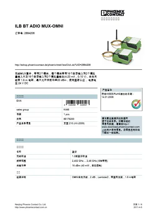
菲尼克斯无线模块
- 格式:pdf
- 大小:208.13 KB
- 文档页数:6

HAC-UM96Ul t r a Lo w P o we rDa t a Ra d i o Mo d ul eI.F e a t ur e s o f HAC-UM96u l t r a L o w P o we r Da t a Ra d i o Mo d ul e1.Ul t r a l o w p o we r t r a n s mi s s i o n wi t h t h e t r a n s mi s s i o np o we r o f 10mW2.I SM f r e q u e n c y b a n d, r e q u i r i n g o n a p p l i c a t i o n o f f r e q u e n c y p o i n t.Ca r r i e r f r e q u e n c yo f433MHz, a l s o c a p a b l e o f p r o v i d i n g 450MHz c a r r i e r f r e q u e n c y.3.Hi g h a n t i-i n t e r f e r e n c e a n d l o w B ER(B i t e r r o r R a t e)Ba s e d o n t h e GF SK mo d u l a t i o n mo d e, t h e h i g h-e f f i c i e n c yf o r wa r d e r r o r c o r r e c t i o n c h a n n e le n c o d i n g t e c h n o l o g y i s u s e d t o e n h a n c e d a t a’s r e s i s t a n c e t o b o t h b u r s t i n t e rf e r e n c e a n dr a n d o m i n t e r f e r e n c e a n d t h e a c t u a l b i t e r r o r r a t e o f 10-5 ~ 10-6 c a n b e a c h i e v e d wh e n c h a n n e lb i t e r r o r r a t e i s 10-2.4.Lo n g t r a n s mi s s i o n d i s t a n c eW i t h i n t h e r a n g e o f v i s i b i l i t y, t h e r e l i a b l e t r a n s mi s s i o n d i s t a n c e i s >300m wh e nt h e h e i g h t i sg r e a t e r t h a n 2m (B ER=10-3/9600b p s).W i t h i n t h e r a n g e o f v i s i b i l i t y, t h e r e l i a b l e t r a n s mi s s i o n d i s t a n c e i s >500m wh e n t h e h e i g h t i sg r e a t e r t h a n 5m (B ER=10-3/9600b p s).5.Tr a n s p a r e n t d a t a t r a n s mi s s i o nTr a n s p a r e n t d a t a i n t e r f a c e i s o f f e r e d t o s u i t a n y s t a n d a r d o r n o n s t a n d a r d u s e r p r o t o c o l. An yf a l s e d a t ag e n e r a t e d i n th e ai r c a n b e f i l t r a t e d a u t o ma t i c a l l y(W h a t h a s b e e n r e c e i v e d i se x a c t l y wh a t h a s b e e n t r a n s mi t t e d).6.Mu l t i-c h a n n e lTh e s t a n d a r d HAC-UM96 c o n f i g u r a t i o n p r o v i d e s8c h a n n e l s. I f t h e u s e r n e e d s, i t c a n b ee x t e n d e d t o 16/32 c h a n n e l s, me e t i n g t h e mu l t i p l e c o mmu n i c a t i o n c o mb i n a t i o n mo d e of t h eu s e r.7.Dual serial port, 3 interface modesHAC-UM96 provides 2 serial ports and 3 interfaces, with COM1 as the TTL level UART interface and COM2 as user defined standard RS-232/RS-485 interface (user only needs to plug/pull 1 bit short circuiter and energize it to mak e the definition).rge data buffer zoneInterface baud rate which is set before ex-factory is1200/4800/9600/19200/38400bps with format of 8N1/8E1 and user self-definition, allowing the transmission of long data frames at one time for more flexible programming by users. (If the user needs, it can also transmit the data in unlimited length at one time).9.Intelligent data control and the user doesn’t need to prepare excessive programsEven for semi duplex communication, the user doesn’t need to prepare excessive programs, only receiving/transmitting the data from the interface. HAC-UM96 will automatically complete the other operations, such as transmission/receiving conversion in the air, control, etc.10.Low power consumption and sleeping functionFor receiving, current is <30mA, transmitting current is <40mA, and sleep current is <20uA.11.High reliability, small and lightSingle chip radio-frequency integrated circuit and single chip MCU are used for lessened peripheral circuits, high reliability, and low failure rate.II.Ap p lic ation of series HAC-UM96ultra low p ower data radio module Series HAC-UM96ultra low power data radio module is suitable for:Wireless meter readingIndustrial remote control and remote testAutomatic data collecting systemBuilding automation, safety and security, powerhouse equipment wireless monitor, entrance control systemP OS system, wireless k eyboard, mouseIII.How to use series HAC-UM96ultra low p ower data radio module Series HAC-UM96ultra low power data radio module provides three interface modes including standard RS-232,RS-485 and UART/TTL levels allowing direct connection withcomputer, user’s RS-485 device, monolithic processor and other UART components for application. The schematic circuit of HAC-UM96 is shown below:1.Power supplyHAC-UM96 uses DC power supply with voltage of +3.3~5.5V.The working voltage can be reduced down to 3V based on the user’s needs.It can also share power supply with other equipment, however, the high quality power s upply with desirable ripple factor should be selected. If possible, 7805 chip or other voltage-stabilizing chip should be used for separate power supply. In addition, the reliable grounding must be used if there is other device in the system equipment. In case of failure to connect with the earth, it can form its own grounding but it must be absolutely separated from the municipal electric supply.Under working condition, transmission current is≤40mA, receiving current is≤30mA and sleeping current is ≤20uA.2.Definition of HAC-UM96 connecting terminalHAC-UM96 can supply one9-pin connector (J P1), and its definitions as well as connection method for terminals are shown in Table 1.Table 1: Definition of connecting pins and connection methodPin NoPinNameDescription Level Connected tothe terminalRemarks1GND Grounding of powersupply Grounding of power supply2Vcc Power supply DC+3.3~5.5V3RxD/TTL Serial data receivingend TTLTxD4TxD/TTL Serial data transmittingendTTLRxdCOM15SGND Grounding of the signal 6A(TxD) A of RS-485or TxD of RS-232A(RxD)7B(RxD) B of RS-485 or RxD of RS-232B(TxD)COM2See Page 3,48SLEEP Sleep control (input)TTL Sleep signal Low efficiencyt>15ms9RESET Reset (input)TTL Reset signal Negativeimpulse reset3.Sketch map of connection between HAC-UM96 and terminal equipment (see below)4.Setting of channel, interface and data format:Before using HAC-UM96, the user needs to make simple configuration based on its own needs to determine the channel, interface mode and data format.There is one group of 5-bit short-circuit j umper wire (JP2) on the upper right corner of HAC-UM96, defined as ABCDE respectively.Assuming the open circuit of j umper wire (without short circuiter) is mode 1 and short circuit of j umper wire (with short circuiter) is mode 0, then the configuration is as follows:a. Channel configuration:ABC j umper wires of JP2 provide 8 options, and the user can choose to use 0-7 channels through ABC j umper wires. Within one small communication network, as long as ABC j umper wire mode is same, there can be mutual communication.Table 2: Corresponding frequency points of 0~7 channelsChannel No.Frequency Channel No.FrequencyCBA=000(0)430.2000 MHz CBA=100(4)434.6940 MHzCBA=001(1)431.4288MHz CBA=101(5)434.2332MHzCBA=010(2)431.7360 MHz CBA=110(6)433.1580 MHzCBA=011(3)430.5072MHz CBA=111(7)433.9260MHzNote: The frequency points corresponding to each channel can be adjusted based on the user’s needs.A=1,B=1,C=1 (without short circuiter)A=0,B=0,C=0 (with short circuiter)b. Selection of interface mode:HAC-UM96 provides 2 serial ports. COM1 (Pin3 and Pin4 of JP1) is fixed as UART serial port of TTL level; COM2 (Pin6 and Pin7 of JP1) can choose interface mode through D of JP2:D=1 (without short circuiter) COM2 = RS-485D=0 (with short circuiter) COM2 = RS-232The following attention should be paid for the two serial ports provided by HAC-UM96:i.For the data received from the air, when HAC-UM96 transmits it to the terminalequipment through serial port, COM1 and COM2 output simultaneously, i.e. if the userconnects one device at COM1 and COM2 respectively, they can receive the datasimultaneously.ii.For the data transmitted from the terminal equipment and ready to transmit to the air, HAC-UM96 can only receive the data sent from either COM1 or COM2 but notsimultaneously.Suggestion: The user only connects to use one serial port of COM1 or COM2.c. Parity mode selection:HAC-UM96 can support no-parity or even parity modes of the serial communication UART, i.e.8N1/8E1. It can choose parity mode through E of JP2:E=1 (without short circuiter) Parity: 8E1 (even parity)E=0 (with short circuiter) Parity: 8N1 (no parity)I f j u mp e r i s a l t e r e d,i t b e c o me e f f e c t i v e a f t e r e l e c t r i f y.5.Transparent data transmissionTransparent data interface is offered to suit any standard or nonstandard user protocol. Any false data generated in the air can be filtrated automatically (What has been received is exactly what has been transmitted).6. Low Power Consumption (Sleep State) Function:HAC-UM96module supports the Sleep function that can further reduce its power consumption.In sleep state, the supply current consumption can be less than 20uA.We always disable this function as the factory default setting if it is not required. As the result, HAC-UM never entersa sleep state mistakenly in that case. If the sleep function is necessary, customers shouldindicate this in order so we can enable it before delivery.a. Using the Sleep function:When the SLP (SLEEP) signal on JP1 pin 8 is continuously high, HAC-UM keeps in sleep state.The SLP signal can convert HAC-UM from idle to sleep state in 10us after its rising edge. If the SLP signal reaches on HAC-UM receiving or transmitting data, this module cannot enter sleep state until this data group transmission completed.If the SLP (SLEEP) signal is continuou sly high, HAC-UM keeps in active state. The SLP signal can convert HAC-UM from sleep to active state in 1ms after its falling edge in order to ensure that CPU clock works stably again.To disable the sleep function for HAC-UM96, the SLEEP pin should be ground or zero.b. Application Notes:For those HAC-UM96 modules with the sleep function enabled, they may enter sleep state by error in case of improper power on. So we recommend that an additional reset signal is required for HAC-um after at least 150 ms of main CPU program delay when the module is powered on.7.Sketch map of structural size (see below):IV.Application of series HAC-UM96 network ingThe communication channel of HAC-UM96 is semi duplex, which is most suitable for the communication mode of point to multi-point. Under this mode, one master station must be set, and all of the rest are slave stations. A unique address is given to each station. The coordination of communication is controlled by master station that uses data frames containing address code to transmit data or command. Slave station will receive all of the data and command and compare the received address code with local address code. If they are different, the data will be deserted without any response. If those address codes are the same, it means the data is sent to the local. Slave station will make different responses according to the transmitted data or command and send back the data of response. All these jobs must be performed by upper protocol, and it is assured that there is only one transmitter-receiver in the state of transmission in the communication network at any instant moment so as to avoid the cross-interference.HAC-UM96 can also be used for point-to-point communication with easier operation. For the programming of serial port, all you have to do is to remember that its communication mode is semi duplex while always observing the time sequence of come-and-go for receiving and transmitting.V.Tech nical specification of HAC-UM96Modulation mode: GFSKWorking frequency: 429.00~433.30MHz (customization for 450~470MHz)Transmission power: 10dBmInterface data format: 8E1/8N1Receiving sensitivity:-112dBm@9600bpsWorking temperature: -10℃~60℃(customization for -30℃~70℃)Power supply:+3.3 ~ 5.5VDCDimension:47×26×10mmTransmitting current: ≤40mAReceiving current:≤30mAsleep current :<20μAInterface velocity: 9600b p sWorking humidity: 10%~90% relative humidity without condensationVI.Description of ty peFor HAC-UM96product type, HAC indicates the name of manufacturer Shenzhen HAC Technology Co., Ltd., UM96 indicates ultra low power, i.e. transmission power is 10dBm, and96 indicates that interface baud rate is 9600bps, and 1200bps is HAC-UM12.Note: The user can’t set the communication rate of HAC-UM96 itself. The user chooses when placing the order and it is already set when delivered from the factory.。

菲尼克斯5100无线模块故障判断菲尼克斯5100无线模块是一种常用的无线通讯设备,但在使用过程中有时会出现故障。
本文将从以下几个方面介绍如何判断菲尼克斯5100无线模块故障。
一、通讯距离问题菲尼克斯5100无线模块的通讯距离一般为300米,但实际使用中受到环境和设备因素的影响,通讯距离可能会受到限制。
如果发现菲尼克斯5100无线模块的通讯距离变短或无法连接,首先需要检查是否是距离问题。
可以尝试将接收机和发射机之间的距离缩短,或者更换更高灵敏度的天线。
二、电源问题菲尼克斯5100无线模块需要稳定的电源供应,如果电源不足或不稳定,可能会导致无法正常工作。
因此,在判断故障时,需要检查电源是否正常。
可以使用万用表检测电压是否稳定,并检查电源线是否松动或损坏。
三、接口问题菲尼克斯5100无线模块的接口包括串口和GPIO接口,如果接口连接不良或者接线错误,可能会导致无法通讯。
在判断故障时,需要检查接口是否连接正常,接线是否正确。
如果需要,可以使用示波器检测串口波形是否正确,以判断故障原因。
四、程序问题菲尼克斯5100无线模块的程序需要正确配置和编写,否则会导致无法正常通讯。
在判断故障时,需要检查程序是否正确配置,并检查是否有编写错误。
可以使用调试工具或者日志查看工具来帮助排查故障原因。
五、硬件故障如果以上几个方面都检查正常,仍然无法正常通讯,可能是菲尼克斯5100无线模块本身出现了硬件故障。
在判断故障时,需要检查是否有明显的物理损坏或者焊接不良等问题。
如果需要,可以将模块送到专业维修机构进行检测和维修。
菲尼克斯5100无线模块故障的判断需要综合考虑多方面的因素,需要仔细排查每个可能的故障原因,以确定正确的解决方案。
同时,还需要注意安全问题,避免因为操作不当导致更严重的故障或者人身伤害。
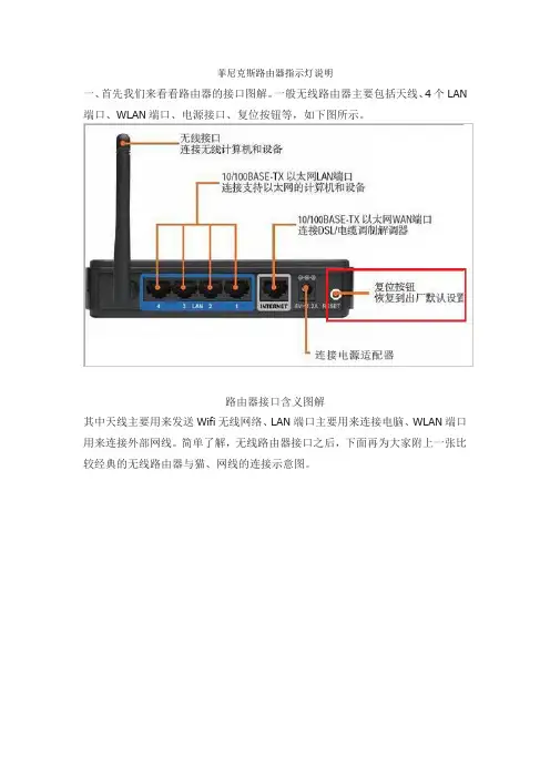
菲尼克斯路由器指示灯说明一、首先我们来看看路由器的接口图解。
一般无线路由器主要包括天线、4个LAN 端口、WLAN端口、电源接口、复位按钮等,如下图所示。
路由器接口含义图解其中天线主要用来发送Wifi无线网络、LAN端口主要用来连接电脑、WLAN端口用来连接外部网线。
简单了解,无线路由器接口之后,下面再为大家附上一张比较经典的无线路由器与猫、网线的连接示意图。
路由器、猫、电脑以及网线连接示意图如果出现无线路由器无法上网,首先检查下路由器、猫、电脑以及网线连接是否正常,如果路由器设置没有问题,下面我们就可以通过路由器工作时的指示灯含义,判断路由器的故障了。
无线路由器指示灯图解路由器指示灯通常可以分为4类,分别是电源指示灯、SYS系统指示灯、LAN指示灯、WAN指示灯,这四个指示灯含义如下:●电源指示灯这个指示灯是电源联通电源的指示灯,正常工作必须常亮,不亮说明电源没插好或者路由器坏了。
●SYS系统指示灯这个SYS系统指示灯是路由器的工作状态指示灯,闪烁代表正常,如果SYS系统指示灯不亮或者会亮,但不会闪烁,那么基本是路由器出现问题了。
●LAN指示灯LAN接口是与电脑连接的,如果将网线将此接口和电脑的网卡接口连接,开启电脑后,LAN指示灯是会亮的,如果不亮说明接口或者网线出现问题。
接口问题可能是路由器接口或者电脑网卡接口问题。
●WAN指示灯WAN指示灯显示的是外部宽带线信号指示灯。
常亮表示端口与前端猫连接正常。
当有数据传输,比如有设备在上网的时候,正常情况就会数据传输,传输过程中,WLAN端口就会不断的闪烁。
如果WAN指示灯不亮,则说明猫或者外部网线有问题,如果WAN指示灯亮但不闪烁,并且手机、电脑无法上网的话,那么主要是网络线路存在问题,可以电话咨询网络服务商,确认是否宽带线路出现故障。
随着路由器的流行,如今很多网友家中基本都有无线路由器,如果今后遇到路由器无法上网,要记得查看路由器指示哦,通过分析路由器指示灯的含义,就可以大致判断出到底是路由器、网线还是联网设备的问题了。

菲尼克斯安全输入模块指示灯说明菲尼克斯安全输入模块的指示灯是一种重要的功能,它可通过不同的颜色和闪烁频率来传达不同的状态信息。
了解并正确理解这些指示灯的含义,将帮助我们更好地操作和维护设备。
以下是菲尼克斯安全输入模块常见的几种指示灯及其说明。
1. 绿色稳定亮灯:当看到绿色指示灯以稳定的状态亮起时,这表示设备处于正常工作状态。
我们应该高兴地看到这个信号,因为它意味着我们的系统是安全的,并且一切运行正常。
2. 红色稳定亮灯:当红色指示灯以稳定的状态亮起时,这表示设备遇到了问题或错误。
我们应该立即停止设备的操作,并排除故障原因。
可以检查连线是否正确连接,或者观察其他部分是否有损坏。
3. 蓝色闪烁灯:当蓝色指示灯以闪烁的方式亮起时,这表示设备正在进行设置或配置。
在这种情况下,我们应该等待一段时间,直到蓝色指示灯停止闪烁,然后设备将恢复正常工作状态。
4. 黄色闪烁灯:当黄色指示灯以频繁的闪烁方式亮起时,这表示设备正在进行自检或自动校准。
这是一个正常的过程,我们应该耐心等待设备完成自检或校准工作。
在此期间,我们应避免对设备进行其他操作,以确保自检和自动校准的准确性。
此外,还要注意指示灯的亮度和闪烁频率可能会根据每个设备的型号和制造商有所不同。
因此,在使用设备之前,应详细阅读设备的用户手册,以了解正确的指示灯含义和操作方法。
总之,菲尼克斯安全输入模块的指示灯是我们了解设备状态的重要工具。
通过正确理解和识别不同的指示灯,我们可以更好地操作和维护设备,及时解决问题,确保设备的正常运行。
记住,设备故障时请及时停止操作,并进行排查。
以正确的方式使用和维护设备,能够更好地保护我们的宝贵资产和人身安全。
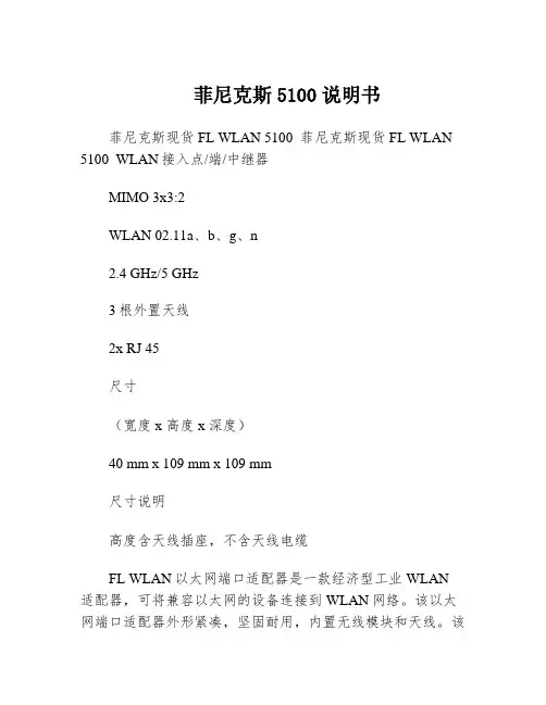
菲尼克斯5100说明书菲尼克斯现货FL WLAN 5100 菲尼克斯现货FL WLAN 5100 WLAN接入点/端/中继器MIMO 3x3:2WLAN 02.11a、b、g、n2.4 GHz/5 GHz3根外置天线2x RJ 45尺寸(宽度 x 高度 x 深度)40 mm x 109 mm x 109 mm尺寸说明高度含天线插座,不含天线电缆FL WLAN以太网端口适配器是一款经济型工业WLAN 适配器,可将兼容以太网的设备连接到WLAN网络。
该以太网端口适配器外形紧凑,坚固耐用,内置无线模块和天线。
该设备防护等级达IP65,可直接现场安装,通过带M12连接器的以太网电缆连接到自动化设备。
优势:可直接在集成到应用以太网端口适配器的主要应用领域安装快捷轻松安装在现场以太网端口适配器是一种简易解决方案,可轻松将带以太网接口的工业自动化设备连接到WLAN网络。
该设备防护等级达IP65,可直接现场安装,通过带M12连接器的以太网电缆连接到自动化设备。
优势:内置天线的紧凑型IP65模块用于以太网和电力传输的M12接口轻松安装在现场自动组态,调试更简单安全通过Mode按钮轻松组态使用Mode按钮,无需组态即可轻松快速地构建安全的点到点网络和小型网络。
此外,也可通过网络浏览器轻松组态。
通过AT命令进行高级设置轻松组态和控制FL EPA 2在WLAN EPA模块运行过程中,可通过控制器发出的简单AT命令对其进行自动组态和控制。
这样就可以通过移动系统的控制器根据位置对漫游过程(即接入点之间的转换)进行控制。
FL EPA产品一览特性FL EPA 2FL EPA 2 RSMAWLAN标准IEEE 02.11a/b/gIEEE 02.11 a/b/g频段和道(*依不同国家而定)2.4 GHz,1-11道5 GHz:36-140道(端)5 GHz:36-4道(接入点)2.4 GHz,1-11道5 GHz:36-140道(端)5 GHz:36-4道(接入点)大数据速率(总值)54Mbps54 Mbps大数据流量(净值)< 20 Mbps< 20 Mbps运行模式端(单端网桥、多端网桥)(微型接入点)两个FL EPA模块之间的无线网桥端(单端网桥、多端网桥)(微型接入点)两个FL EPA模块之间的无线网桥大传输功率2.4 GHz:17 dBm(包括天线)5 GHz:15 dBm(包括天线)2.4 GHz:17 dBm(包括天线)5 GHz:15 dBm(包括天线)天线数1(内置)1(外置),RSMA接口安装后的防护等级IP65IP65环境温度(工作)-30°C … 60°C … 65°C电源9 … 30 V DC,大1.7 W9 …30 V DC,大1.7 W特殊性能双无线板:WLAN和蓝牙双无线板:WLAN和蓝牙功能强大的WLAN IEEE 02.11n模块,通范围更广采用新标准和MIMO技术,扩展通范围该设备有*的无线号,并采用符合IEEE 02.11n标准的MIMO(多点输入,多点输出)多天线技术,可在长距离范围内实现稳定、高速且可靠的无线通。

菲尼克斯5100无线模块故障判断(原创版)目录1.菲尼克斯 5100 无线模块概述2.故障现象及原因3.故障判断方法4.故障处理措施5.总结正文【菲尼克斯 5100 无线模块概述】菲尼克斯 5100 无线模块是一款高性能、稳定可靠的无线通信设备,广泛应用于工业自动化、电力系统、交通运输等领域。
该模块支持多种通信协议,具有较高的抗干扰能力和良好的传输性能。
【故障现象及原因】在实际应用中,菲尼克斯 5100 无线模块可能会出现故障,导致通信异常。
常见的故障现象包括:1.无法建立连接:模块无法与对端设备建立通信连接。
2.信号不稳定:通信过程中信号时强时弱,导致数据传输错误。
3.通信距离缩短:通信距离明显小于正常值,影响通信质量。
故障原因可能包括:1.模块硬件故障:如模块损坏、接触不良等。
2.天线故障:如天线损坏、连接松动等。
3.通信环境恶劣:如电磁干扰、信道拥堵等。
4.配置参数错误:如工作频率、发射功率等设置不合理。
【故障判断方法】针对菲尼克斯 5100 无线模块的故障现象,可以通过以下方法进行判断:1.检查硬件:查看模块及连接线路是否完好,确认天线是否损坏或连接松动。
2.观察指示灯:根据模块指示灯的状态判断模块是否正常工作。
例如,绿灯闪烁表示正在建立连接,红灯闪烁表示故障。
3.信号强度测试:使用信号强度计检测模块接收到的信号强度,评估通信环境。
4.数据传输测试:通过数据传输测试软件检测数据传输速率和准确性。
5.查看配置参数:检查模块的工作频率、发射功率等配置参数是否合理。
【故障处理措施】根据故障判断结果,采取相应的处理措施:1.硬件故障:更换损坏的模块或连接线路,修复天线。
2.天线故障:更换损坏的天线,确保连接牢固。
3.通信环境恶劣:改善通信环境,如远离电磁干扰源、更换信道等。
4.配置参数错误:调整模块的工作频率、发射功率等配置参数至合理范围。

皮带卸料小车控制系统的改造与应用本文针对皮带卸料小车在日常运行状态下,与其配套搭载的移动电缆滑线小车存在故障率高、维修难度大、维护成本高等问题,设计采用电缆卷筒供电方式结合无线蓝牙传输技术实现皮带卸料小车稳定供电,降低了设备维护成本,提高了设备利用率。
标签:卸料小车;蓝牙;自动控制1、皮带卸料小车简介1.1 用途及其重要性皮带卸料小车是化工生产过程中输送系统必不可少的布料设施,其作用是将给料皮带机上的物料按照指令布料于指定的料仓中。
卸料小车在实现多料仓布料过程中,需要沿着给料皮带机运行方向往复行走,为卸料小车供电的移动电缆滑线小车同样沿滑线往复行走。
在此过程中,移动电缆滑线小车供电的稳定性,直接影响整个系统运行的效率,而移动电缆滑线小车的返修率同样影响着整个系统的设备维护成本。
1.2 结构组成目前,皮带卸料小车因具体使用工段不同,结构存在微小差异,但大体结构相同,机械设备包括送料皮带、收尘罩、卸料可逆皮带、小车轨道、送料皮带架等,电气设备包括卸料小车驱动电机、卸料可逆皮带驱动电机、小车抱闸线圈、皮带跑偏开关等,示意图如图1所示:1、送料皮带2、收尘罩3、卸料可逆皮带4、跑偏检测开关5、小车轨道6、送料皮带架7、旋转编码器2、存在的问题及其原因分析2.1 存在的问题我厂卸料小车配备的控制柜位于低压配电室,供电电缆采用3根三芯柔性电力电缆和2根两芯柔性信号电缆,这5根电缆通过滑线小车与卸料小车连接,并随卸料小车在小车轨道上移动,这种供电和信号传输方式导致滑线小车和电缆频繁出现故障,由此引发DCS控制系统无法实现卸料小车的精准定位。
在实际生产操作过程中,操作人员在现场使用“手动”按钮控制卸料小车实现对不同料仓的卸料,此操作需要操作人员现场看护卸料小车是否到位,而卸料现场环境极差,高粉尘和高噪音严重影响操作人员的身体健康,除此之外,连续的“手动”控制卸料小车,操作人员不能及时掌握料仓的料位,导致进料不均衡,影响后续上料系统的运行,无法充分发挥DCS控制系统的优势。
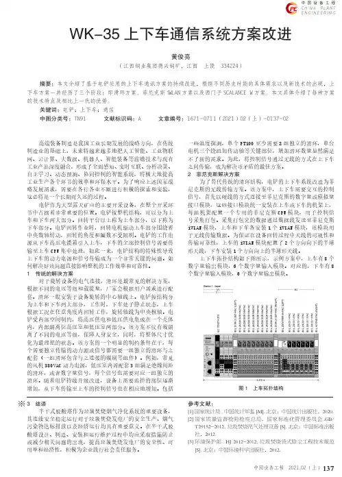
137中国设备工程C h i n a P l a n t E n g i n e e r i ng中国设备工程 2021.02 (上)高端装备制造是我国工业长期发展的战略方向,在传统制造业的基础上,未来将越来越多地把人工智能、工业物联网、云计算、大数据、机器人、智能装备等前瞻技术与现有工业产品深度融合,形成了全面感知、实时互联、分析决策、自主学习、动态预测、协同控制的智能系统,将极大地提高工业生产各个环节的效率和环保水平。
为了响应上述国家战略发展需求,需要在各行各业不断进行积极的探索和实验,这必将是一个长期而久远的过程。
电铲作为大型露天矿山的主要开采设备,在整个开采环节中占据着非常重要的位置。
电铲按整机结构,可以分为上车和下车两大部分。
回转平台以上称为上车部分,以下称为下车部分。
电铲回转作业时,回转电机驱动上车部分围绕着中央数轴转动,回转的角度和圈数不受限制。
电铲的工作电源从下车高压电缆箱引入上车,下车的全部控制信号需要传输至上车CPU 集中处理,如此一来,电铲结构的特殊性导致上下车的动力电源和信号传输成为一个非常关键的问题。
如何解决好该问题直接影响整机的工作效率和可靠性。
1 传统的解决方案对于旋转设备的电气连接,滑环是最常见的解决方案,根据不同的电压等级和载流量,厂家会根据用户需求进行配套。
滑环一般安装于设备旋转的中心轴线上。
电铲按结构分为上车和下车两大部分,工作时,下车处于静止状态,上车根据工况在任意角度内回转工作,旋转轴线为中央枢轴。
电铲受内部空间制约,将高压供电和低压供电集成在一个壳体内,内部隔离位高压室和低压室两部分。
该方案不仅有效隔离了不同的电压等级,保障人身安全,同时,将整体尺寸优化为最理想的状态。
该方案的一个明显的制约条件在于,每个需要独立传输的动力源或信号都需要一组独立的滑环与之配套(一组滑环包含与之连接的碳刷等组件)。
例如,常见的风机380VAC 动力电源,低压室内需配套3组满足绝缘间距的滑环,或者数字量信号,每个信号也需要对应一组独立的滑环。
菲尼克斯电子断路器说明书
1.商品名称:菲尼克斯电子断路器。
2.商品毛重:1.0kg。
3.安装类型:安装在基座上。
4.颜色:黑色。
5.位数:1。
6.过电压类别GRP:II。
7.绝缘材料:PA66/6。
8.阻燃等级,符合UL94:V0。
9.保险丝:电子。
10.保险丝类型:自动设备。
11.额定过电压:0.5kV。
12.标称工作电压:24VDC。
13.工作电压:18VDC—32VDC。
14.额定电流IN:4A。
15.要求的备用保险丝:不需要,内置本安元件。
16.介电强度:大32VDC(负载电路)。
17.污染等级:2。
18.过电压类别GRP:II。
19.绝缘材料组:I。
20.开关容量ICN:主动电流限制。
21.闭路电流范围I0:典型值25mA±5mA(接通时)。
22.高度:60mm。
23.宽度:12.5mm。
24.深度:70mm。
25.完整模块高度:115mm。
26.完整模块宽度:38mm。
27.完整模块深度:112.5mm。
28.菲尼克斯电子断路器安装说明:当成排安装且无对流冷却时,由
于热影响,在持续操作中,额定设备电流通常大只能达到80%(操作系数)。
为元器件的重新启动,或机械中应采取特殊的措施(如使用安全PLC)。
不允许并行连接多个断路器。
菲尼克斯安全输入模块指示灯说明
菲尼克斯安全输入模块是一种用于保护设备和系统的重要安全装置。
它具有指
示灯功能,可以提供有关系统状态和运行情况的信息。
以下是菲尼克斯安全输入模块指示灯的说明:
1. 电源指示灯:当安全输入模块正常供电时,电源指示灯将亮起。
如果指示灯
不亮,可能表明模块未接通电源或存在电源故障。
需要检查电源线路并重新连接。
2. 输入状态指示灯:安全输入模块的输入状态指示灯用于显示输入信号的状态。
当输入信号正常时,指示灯将保持亮起。
如果输入状态指示灯不亮,可能表示输入信号未正常连接或存在故障。
需要检查输入信号线路并确保其正常连接。
3. 系统状态指示灯:系统状态指示灯用于显示安全输入模块的整体运行状态。
正常情况下,系统状态指示灯将保持亮起。
如果指示灯不亮或闪烁,可能表示安全输入模块存在故障或系统异常。
需要进行系统诊断并修复故障。
4. 报警指示灯:报警指示灯用于显示安全输入模块的报警状态。
当发生安全隐
患或异常情况时,报警指示灯将闪烁或保持亮起,以提醒操作人员注意。
如果报警指示灯持续闪烁,需要查找并解决引起报警的原因。
请注意,在使用菲尼克斯安全输入模块时,正确理解和识别指示灯的功能是至
关重要的。
根据指示灯的显示,可以判断系统的工作状态和是否存在故障。
如果遇到任何指示灯异常或报警提示,请立即采取相应的措施进行排查和处理,确保系统的安全运行。
使用说明DEVICENET+无线IO菲尼克斯电气(南京)研发工程中心有限公司自动化服务中心技术支持热线电话:+86-25-52102908传真:+86-25-52760810邮箱:automation.support@南京江宁236信箱,211100作者: HP日期:01.01.2011 版本: 00 页数:91.参考各模块说明完成接线,上电。
图一:耦合器总线接线图二:耦合器电源接线图三:基站接线图四:无线I/O接线(一)图五:无线I/O数字量接线图六:无线I/O模拟量接线2.参考耦合器和基站说明完成波特率设定、硬件自动配置、地址设定、过程数据字设定的工作。
2.1耦合器有X10和X1两个拨码开关,表示地址的十位和一位,组合起来即为该DeviceNet站的地址。
2.2耦合器波特率设定步骤如下:* 将X1拨码开关设为相应位0:125kbaud1:250kbaud2:500kbaud3:自适应A:使用软件设定波特率* 将X10拨码开关拨到“D”* 等待5秒,RUN的LED灯开始由红色闪烁变为红色常亮* 将X10拨码开关拨到“E”* 等待5秒,RUN的LED灯开始由黄色闪烁变为黄色常亮,这时波特率已经设置好了* 将X10拨码开关拨到“F”* 等待5秒,RUN的LED灯开始由绿色闪烁变为绿色常亮,表示正确的设置步骤已经完成。
* 设置波特率完成后需要重新设置DeviceNet地址。
2.3本地总线硬件配置* 将X1拨码开关拨到“B”,开始自动读取本地总线配置* 将X10拨码开关拨到“D”* 等待5秒,RUN的LED灯开始由红色闪烁变为红色常亮* 将X10拨码开关拨到“E”* 等待5秒,RUN的LED灯开始由黄色闪烁变为黄色常亮,表示硬件配置已经读取。
* 将X10拨码开关拨到“F”* 等待5秒,RUN的LED灯开始由绿色闪烁变为绿色常亮,表示正确的设置步骤已经完成。
* 设置波特率完成后需要重新设置DeviceNet地址。
使用网页代码查询更多信息您可在本手册中找到网页代码,即一个#号加一个四位数的数字组合。
网页代码:#1234(示例)通过网页代码,您可以快速获取网站上的信息。
安装非常简便:1. 登录菲尼克斯电气公司官网2. 在搜索栏输入#和数字组合3. 获取更多信息和产品型号搜索或直接使用链接:/webcode/#1234适用于DIN导轨及现场应用的电子模块壳体菲尼克斯电气的电子模块壳体产品,从外形、颜色到功能都有各式各样的选择,这是我们产品设计的主旨。
无论是壁挂式或DIN导轨式安装,浅灰色或天蓝色,窄型或宽型设计——菲尼克斯电气总能为您的电子模块找到合适的壳体。
现场壳体• 模块化壳体系统,适用于各种场合• 防护等级最高可达IP69K,适用于恶劣的环境条件• 成熟的PCB连接技术支持各种实用型定制• 提供满足客户独特设备设计需求的定制型号• 可安装多种附件,包括定制化的薄膜键盘DIN导轨安装式壳体• 多种导轨式安装标准壳体• 集成菲尼克斯电气各种通用且经典的连接技术• 全系列产品可客制化各种标识和加工方式,实现丰富多样的变化• 根据客户的想法定制开发新产品网页代码:#0514多功能壳体楼宇安装壳体用于电子模块壳体的交互在线选型软件智能搜索引擎,交互式组件选择,实时可视化3D:使用全新的在线选型软件,简单几步即可配置个性化的电子模块壳体。
选择合适的壳体产品系列、尺寸和连接器,即可完成壳体产品的选型。
网页代码:#0512优势• 简单快速地配置个性化壳体零部件• 通过简单的鼠标拖拽动作便可完成配置,即使在移动终端设备上也可进行操作(iOS 和Android系统皆适用)• 以列表形式导出零部件清单,或直接加入购物车在线订购• 实时可视化3D显示• 可下载适配壳体的PCB图纸新品基础型EH 系列壳体可轻松用于通用型设备的设计。
7种宽度,2种高度,3种盖板形式,EH 系列壳体可提供100多种组合方式。
通用应用领域的EH 基础型壳体工业电子产品的设计需要与具体的应用场合相适配。
安装调试1.如何编程ID-PLUG?ID-PLUG就是每个I/O的身份识别卡,决定这个I/O是与哪个基站进行通讯的前提,单个I/O模块为了与基站通讯,需要连接数据,而这个连接数据保存在插入到该模块中的ID-PLUG.在启动I/O模块之前,先把连接数据从基站中写到I/O模块中,具体步骤如下:第一, 确认所有的连接无误;给基站上电;第二, 在”TN”旋转编码开关上设置合适的模块地址;第三, 插入ID-PLUG. ID-PLUG灯先变黄,然后变绿;第四, 拔出编程好的ID-PLUG;第五, 把ID-PLUG插入到I/O模块中。
设置步骤:1)确认编程过的ID-PLUG已插入到I/O模块中;2)确认基站被正确的组态;3)给基站上电.所有连接上的I/O设备的过程数据长度和数能够从旋转编码开关上读到;4)组态本地总线,然后启动本地总线;5)如果基站没有建立起到I/O模块的通讯连接,状态字中的错误位将置位,并且BT灯将显示红色;6)一但无线蓝牙网络通讯建立,就执行一个逻辑检测。
如果过程数据长度设置不正确,BT等将闪烁红色,表示有一个I/O错误发生;7)但逻辑检测完成,BT灯将显示绿色,表示I/O模块可以数据交换。
故障安全:当与I/O模块的无线连接被中断即通讯失败时,I/O模块将切入到失败安全模式。
与I/O模块的过程数据传输中断,所有过程数据置零。
当通讯中断恢复后,必须使用”set failsafe mode run”指令使能I/O模块的过程数据交换.无线通讯的状态可以通过”Get ErrorCode”指令查询。
2.基站的设置:3.耦合器的设置:当基站的设置的设置完成后,就可以进行耦合器的设置工作,具体步骤如下1)确认所有的连接无误;2)上电;3)从站读取自己BT网络的Local Bus:4)在耦合器有两个开关X1和X10,将X1拨到 B ,再将X10拨到D ,等待5秒,RUN闪红灯到不闪,再将X10拨到E ,等待5秒,RUN闪黄灯到不闪,再将X10拨到F ,等待5秒,RUN闪绿灯到不闪,读从站的Local Bus即完成。
FSK超外差式434Mhz无线接收模块的设计射频通信技术已深入各行各业,为解决434MHz无线接收模块在工作中易受到杂波信号干扰,接收灵敏度低的缺点,文章设计了一种高灵敏度、FSK解调方式的无线接收模块方案。
该方案采用INFINEON公司设计的集成度高、分立元件少的TDA5210高频接收芯片,通过在信号接收前端电路中插入高Q值的声表面波滤波器(SAWF,surface acoustic wave filter),增强接收模块的频率选择性,并抑制高次谐波对系统造成的干扰,依据最大功率传输理论,匹配天线端输入阻抗到50欧姆以增强系统对信号的接收强度。
实验表明,该无线接收模块方案具有接收灵敏度高,噪声抑制能力强,工作稳定的特点。
标签:无线接收;434MHz;英飞凌在无线通信技术中,高频信号的频率调制方式由于具有频率响应好、抗干扰能力强、信号保真度高等优点,在各行业中得到了广泛应用。
有限的可用频率资源的充分利用性和电磁兼容等问题对调频无线通信技术的应用严格性的要求,使得人们在遵循无线电技术法规要求的前提下,设计出高稳定性、抗干扰能力强的通信产品以满足品质的需求。
现在市场上普遍采用的是UHF频段的315MHz频段,调制和解调方式大多以ASK为主,433MHz频段近年来得到了广泛应用,如智能家居系统[1]等。
本文针对433MHz频段FSK调制方式的发射端,设计了易于调试的接收端方案,文中给出了详细的调试方法,通过应用高Q值的声表面波滤波器[2](SAWF,surface acoustic wave filter),增强了接收模块的频率选择性,提高了系统的抗干扰能力。
1 芯片介绍TDA5210是INFINEON公司生产的低功耗、具有自动休眠功能的超外差式FSK/ASK解调方式接收芯片,集成度较高,仅需搭载少量的外围器件。
主要适用于远程控制系统,无线进入系统,报警系统和低比特率通信系统。
其内部框图如图1所示。
TDA5210的工作频段可以在400MHz 到440MHz,810MHz到870MHz之间进行选择,该芯片内部集成了低噪放大器[3](LNA),双平衡混频器,压控振荡器(VCO),锁相环电路(PLL),晶体振荡器,限幅器,锁相环FSK 解调电路,数据滤波器,数据限幅器和峰值检波电路[4]。
菲尼克斯安全输入模块指示灯说明菲尼克斯安全输入模块是一种用于保护计算机免受键盘记录攻击的创新安全解决方案。
它不仅提供了高级的输入保护功能,还通过指示灯给用户实时的反馈。
下面我们来详细介绍一下菲尼克斯安全输入模块的指示灯说明。
首先,菲尼克斯安全输入模块的指示灯有三种颜色,分别是绿色、黄色和红色。
这三种颜色分别代表着不同的状态和安全级别,通过观察指示灯的颜色,用户可以及时了解当前的安全状态。
当指示灯为绿色时,表示输入模块处于正常工作状态。
这时候,用户可以放心地进行各种输入操作,键盘的输入信息将会受到全面的保护。
绿色指示灯的出现告诉用户,当前的输入环境是安全可靠的。
当指示灯为黄色时,表示输入模块检测到了一些潜在的风险。
这时候,用户需要注意,并根据具体情况采取相应的措施。
可能是输入设备被篡改,或者是存在一些未知的风险因素。
用户可以通过检查设备连接情况、及时更新安全软件、勿随便下载陌生软件等方式来增加安全性。
当指示灯为红色时,表示输入模块检测到了严重的安全威胁。
这时候,用户必须立即采取行动来解决问题。
可能是存在恶意软件、网络攻击等,用户应该断开网络连接、尽快清除恶意软件、及时更换输入设备等。
红色指示灯的出现意味着用户的输入环境已经受到了严重的威胁,必须及时处理以避免造成更大的损失。
总的来说,菲尼克斯安全输入模块的指示灯通过不同的颜色给用户提供了及时准确的安全状态反馈。
用户可以根据指示灯的颜色,快速判断当前的安全情况,并采取相应的防范措施。
同时,通过遵循一些基本的安全操作规范,如定期更新软件、使用高级加密技术等,用户还可以进一步提高输入环境的安全性。
在今天的互联网时代,网络安全已经变得尤为重要。
而菲尼克斯安全输入模块的指示灯说明为用户提供了一种简单有效的安全保护手段。
希望大家在使用计算机的过程中,能够重视菲尼克斯安全输入模块的指示灯,及时识别和应对安全威胁,保护个人隐私和信息安全。
让我们共同营造一个更加安全可靠的网络环境。