霍尔线性器件SS3503使用手册
- 格式:pdf
- 大小:109.24 KB
- 文档页数:4
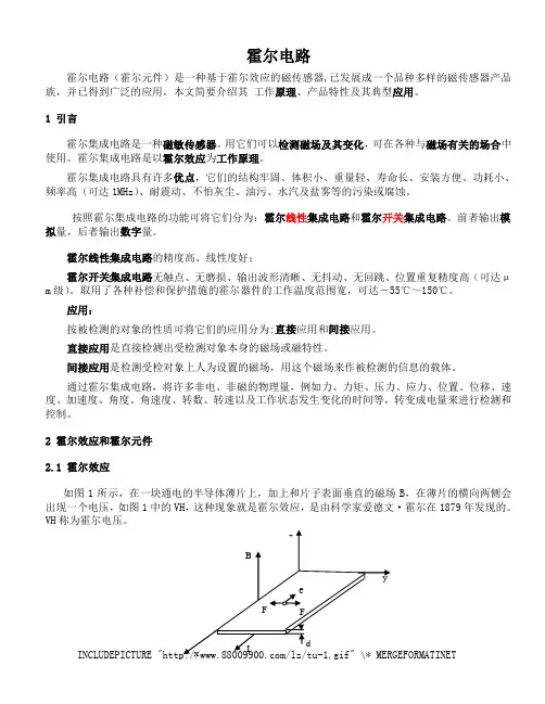
霍尔元件应用及与磁钢的配合使用1 霍尔器件的应用1.1 应用的一般问题1.1.1 测量磁场使用霍尔器件检测磁场的方法极为简单,将霍尔器件作成各种形式的探头,放在被测磁场中,因霍尔器件只对垂直于霍尔片的表面的磁感应强度敏感,因而必须令磁力线和器件表面垂直,通电后即可由输出电压得到被测磁场的磁感应强度。
若不垂直,则应求出其垂直分量来计算被测磁场的磁感应强度值。
而且,因霍尔元件的尺寸极小,可以进行多点检测,由计算机进行数据处理,可以得到场的分布状态,并可对狭缝,小孔中的磁场进行检测。
1.1.2 工作磁体的设置用磁场作为被传感物体的运动和位置信息载体时,一般采用永久磁钢来产生工作磁场。
例如,用一个5×4×2.5(mm3)的钕铁硼Ⅱ号磁钢,就可在它的磁极表面上得到约2300高斯的磁感应强度。
在空气隙中,磁感应强度会随距离增加而迅速下降。
为保证霍尔器件,尤其是霍尔开关器件的可靠工作,在应用中要考虑有效工作气隙的长度。
在计算总有效工作气隙时,应从霍尔片表面算起。
在封装好的霍尔电路中,霍尔片的深度在产品手册中会给出。
因为霍尔器件需要工作电源,在作运动或位置传感时,一般令磁体随被检测物体运动,将霍尔器件固定在工作系统的适当位置,用它去检测工作磁场,再从检测结果中提取被检信息。
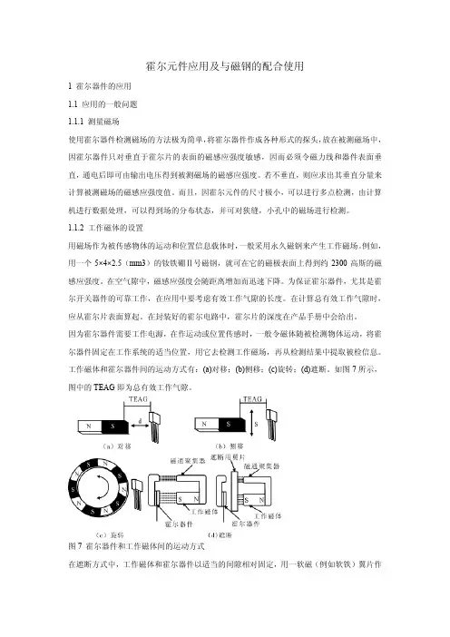
工作磁体和霍尔器件间的运动方式有:(a)对移;(b)侧移;(c)旋转;(d)遮断。
如图7所示,图中的TEAG即为总有效工作气隙。
图7 霍尔器件和工作磁体间的运动方式在遮断方式中,工作磁体和霍尔器件以适当的间隙相对固定,用一软磁(例如软铁)翼片作为运动工作部件,当翼片进入间隙时,作用到霍尔器件上的磁力线被部分或全部遮断,以此来调节工作磁场。
被传感的运动信息加在翼片上。
这种方法的检测精度很高,在125℃的温度范围内,翼片的位置重复精度可达50μm。
图8 在霍尔器件背面放置磁体也可将工作磁体固定在霍尔器件背面(外壳上没打标志的一面),让被检的铁磁物体(例如钢齿轮)从它们近旁通过,检测出物体上的特殊标志(如齿、凸缘、缺口等),得出物体的运动参数。
摘要本文着重介绍了一种基于AT89S52单片机控制的智能型金属探测器的硬件组成、软件设计、工作原理及主要功能。
该金属探测器以AT89S52单片机为核心,采用线性霍尔元件UGN3503作为传感器,来感应金属涡流效应引起的通电线圈磁场的变化,并将磁场变化转化为电压的变化,单片机测得电压值,并与设定的电压基准值相比较后,决定是否探测到金属。
系统软件采用汇编语言编写。
在软件设计中,采用了数字滤波技术消除干扰,提高了探测器的抗干扰能力,确保了系统的准确性。
此外,文中还对影响金属探测器的灵敏度与稳定性的因素进行了探讨,认为仪器的工作频率、检测线圈的尺寸及匝数等是影响灵敏度的主要因素;而应用现场的环境温度、湿度及线圈的制作工艺和供电电源的稳定程度是仪器稳定性的影响因素。
关键词:单片机,金属探测器,线性霍尔元件,电磁感应,灵敏度ABSTRCTThis paper describes the composition of hardware and software,working principles and the functions of an intelligent metal detector which mainly consists of AT89S52 Single-Chip Microcomputer and linear Hall-Effect Sensor. The equipment adopts UGN3503U linear hall-effect sensor as probe to detect the magnetic field change of the centre of a search coil resulted from eddy current effect and turn this magnetic field change into voltage change.The Single-Chip Microcomputer measures the peak value of voltage and compares it with reference voltage.Then determine whether detect metel or not.In case of detection of a metallic mass,the Metal Detector porvides an acoustical and optical alarm.The systems software adopts the assmbler language to be written.Inside the software,the digital filter technology is utilized to eliminate thejamming.So the stability of system and measuring veracity are improved.The effect of all factors on sensitivity and stability of Metel Detetor are discussed in this paper.It is concluded that the operating frequency,the size of the search coil and turns are the main factors effected on the sensitivity of the instrument: the environment temperature and humidity in site,the winding technology of coils and the stability of power supply are the factors effected on stability of instrument.KEY WORDS: Single-Chip Microcomputer, metal detector, linear hall-effect sensor, electric-magnetic induction, sensitivity目录前言 (1)第1章分析探测金属的理论依据 (3)1.1理论描述 (3)1.1.1线圈介质条件的变化 (3)1.1.2涡流效应 (4)第2章硬件电路设计 (6)2.1系统组成 (6)2.2硬件电路功能描述 (6)2.2.1线圈振荡电路 (7)2.2.2数据采集电路 (8)2.2.3 A/D转换电路 (12)2.2.4系统控制单元 (15)2.2.5键盘控制电路 (16)2.2.6显示报警电路 (17)2.2.7电源电路 (18)2.3整机工作原理描述 (19)第3章系统软件设计 (20)3.1软件设计思想 (20)3.2数字滤波及算法说明 (21)3.3主程序流程图 (21)3.3.1键盘控制程序设计 (23)3.3.2数字滤波程序设计 (23)3.3.3显示与报警程序设计 (25)第4章主要技术指标分析 (26)4.1主要技术指标分析 (26)4.4.1工作频率 (26)4.4.2灵敏度分析 (26)4.4.3稳定性分析 (26)第5章仿真、调试结果及分析 (27)5.1 仿真、调试目的与内容 (27)5.2 仿真结果及分析 (27)5.3 试验总结 (29)第6章结论 (30)参考文献 (31)致谢 (32)附录1 电路原理图 (33)附录2 各模块程序清单 (34)前言金属探测器作为一种最重要的安全检查设备,己被广泛地应用于社会生活和工业生产的诸多领域。
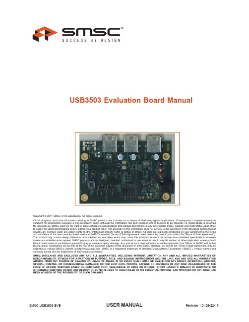
USB3503 Evaluation Board ManualCopyright © 2011 SMSC or its subsidiaries. All rights reserved.Circuit diagrams and other information relating to SMSC products are included as a means of illustrating typical applications. Consequently, complete information sufficient for construction purposes is not necessarily given. Although the information has been checked and is believed to be accurate, no responsibility is assumed for inaccuracies. SMSC reserves the right to make changes to specifications and product descriptions at any time without notice. Contact your local SMSC sales office to obtain the latest specifications before placing your product order. The provision of this information does not convey to the purchaser of the described semiconductor devices any licenses under any patent rights or other intellectual property rights of SMSC or others. All sales are expressly conditional on your agreement to the terms and conditions of the most recently dated version of SMSC's standard Terms of Sale Agreement dated before the date of your order (the "Terms of Sale Agreement"). The product may contain design defects or errors known as anomalies which may cause the product's functions to deviate from published specifications. Anomaly sheets are available upon request. SMSC products are not designed, intended, authorized or warranted for use in any life support or other application where product failure could cause or contribute to personal injury or severe property damage. Any and all such uses without prior written approval of an Officer of SMSC and further testing and/or modification will be fully at the risk of the customer. Copies of this document or other SMSC literature, as well as the T erms of Sale Agreement, may be obtained by visiting SMSC’s website at . SMSC is a registered trademark of Standard Microsystems Corporation (“SMSC”). Product names and company names are the trademarks of their respective holders.SMSC DISCLAIMS AND EXCLUDES ANY AND ALL WARRANTIES, INCLUDING WITHOUT LIMITATION ANY AND ALL IMPLIED WARRANTIES OF MERCHANTABILITY, FITNESS FOR A PARTICULAR PURPOSE, TITLE, AND AGAINST INFRINGEMENT AND THE LIKE, AND ANY AND ALL WARRANTIES ARISING FROM ANY COURSE OF DEALING OR USAGE OF TRADE. IN NO EVENT SHALL SMSC BE LIABLE FOR ANY DIRECT, INCIDENTAL, INDIRECT, SPECIAL, PUNITIVE, OR CONSEQUENTIAL DAMAGES; OR FOR LOST DATA, PROFITS, SAVINGS OR REVENUES OF ANY KIND; REGARDLESS OF THE FORM OF ACTION, WHETHER BASED ON CONTRACT; TORT; NEGLIGENCE OF SMSC OR OTHERS; STRICT LIABILITY; BREACH OF WARRANTY; OR OTHERWISE; WHETHER OR NOT ANY REMEDY OF BUYER IS HELD TO HAVE FAILED OF ITS ESSENTIAL PURPOSE, AND WHETHER OR NOT SMSC HAS BEEN ADVISED OF THE POSSIBILITY OF SUCH DAMAGES.1 IntroductionThis user manual is for the USB3503 Evaluation board. This board can be used to test and evaluatethe functionality of the USB3503 and is ideal for early system integration and software development.The USB3503 EVB provides access to the HSIC upstream and USB downstream ports, as well as theI2C communication pins.SMSC also has evaluation software that can be used with the USB3503 EVB connected to a TotalPhase Aardvark adaptor. This software allows the user to configure the USB3503 in different waysbefore enumeration as well as monitor and manipulate select status registers during enumeration. Thesoftware can be used to prototype microprocessor software, evaluate the different configurations, andtest how the desired configuration fits into the entire system.2 Operation2.1 Contents of the KitThe USB3503 EVB includes the basic equipment necessary to evaluate the USB3503. The itemsincluded in the kit are:B3503 EVB2.5V DC Power Supply3.Documentation and Software CDThe kit does not include any downstream USB devices, I2C master hardware, or other componentsfor board customization.2.2 Initial Bring UpThe USB3503 EVB has a default configuration that allows it to operate as a stand alone hub. To begin,connect the U.FL connectors to the HSIC host. Then, plug the evaluation board into the 5V powersupply. The USB3503 EVB will enumerate as a Generic USB Hub, with the VID and PID equal to thedefault values found in the USB3503 Datasheet.The default configuration of the USB3503 is to enumerate as a Self Powered Hub. This means that,according to the USB 2.0 specification, the downstream ports are only allowed to provide 500mA ofcurrent to the downsteam device.Refer to the next chapters to see the customization options associated with the evaluation kit.3 HardwareThe USB3503 EVB is a board that demonstrates the capabilities of the USB3503. The board consistsof the HSIC upstream and USB downstream ports, a INT_N LED for visual confirmation of theinterrupts configured, a header exposing the I2C pins, and additional circuitry that is used for I2Ccommunication.Figure3.1 Block Diagram of the USB3503 EVB3.1 HSIC and USB PortsThe downstream USB ports are mounted on the edges of the USB3503 EVB. The downstream portsuse the standard USB Type A receptacle. The label for the port is located near the receptacle. TheHSIC upstream port uses U.FL connectors for Data and Strobe.Downstream3Downstream2Downstream1J3: StrobeJ2: DataFigure3.2 Upstream and Downstream Ports3.2 Test Points, Switches and LEDsThere are multiple test points to confirm that the USB3503 EVB is powered properly. TP1 and TP6connect to GND, TP2 connects to the VBAT pin, and TP3 connects to the VDD_CORE_REG pin.The USB3503 EVB also has three switches to manually control the RESET_N and HUB_CONNECT inputs to the part. Figure 3.3 shows the location of the test points (Red) and switches (Yellow).The USB3503 SCL, SDA, RESET_N, HUB_CONNECT and INT_B pins are also exposed on the J1header. These pins are compatible with the Total Phase Aardvark pinout, where pin 1 of the Aardvark connector connects to pin 1 of header J1 (Refer to Figure 4.1 for the proper way to connect the Aardvark). The INT_N pin is also connected to LED1 to indicate that an interrupt has occurred. The LED remains lit until the interrupt is cleared, as described in the USB3503 datasheet.3.3 Configuration ResistorsThere are eight different resistors used to configure the part when the RESET_N pin transitions from Low (0V) to High(>1.25V). These resistors are used for the REF_SEL pins. Because these resistors and pads pull up to the 1.8V regulator, any changes to these resistors will need to be done with the board unpowered. The resistor pads are laid out in a manner that prevents the pull-up resistors from being populated at the same time as the pull-down resistors, as shown in Figure 3.4. The following tables show the proper configuration resistor population requirements for the desired results, the resistor values should match those found in Section 6, "USB3503 EVB Bill of Materials".Note:The Y1 Oscillator will need to be replaced with the proper frequency if the REF_SEL pins arealtered. Refer to Section 6, "USB3503 EVB Bill of Materials" for recommended oscillator specifications.Figure 3.3 Test points, Switches, Header and LEDTable 3.1 REF_SEL OptionsR18R21R27R30REFCLK(MHZ)EMPTY EMPTY INSTALL INSTALL 38.4EMPTY INSTALL INSTALL EMPTY 26.0 (Default)INSTALLEMPTYEMPTYINSTALL19.2TP2TP1J 1Pin1LED1HUB_CONNECTRESETTP3TP6NOT USED3.4 Additional CircuitryThe U1 Regulator provides 3.3V to the VBAT pin, and also supplies power to the 26MHz clock oscillator. If a higher VBAT voltage is desired, remove R1 and supply the power through TP2.The U2 Regulator provides 1.8V to the VDD_CORE_REG pin as well as providing the pull up voltage for the digital control pins. To provide external power to the VDD_CORE_REG pin remove R8 and supply the power through TP3.The USB3503 can function with a single power supply; to do this remove R8 and place a 0Ohm resistor on R9. This connects the VDD_CORE_REG pin to the VDD33_BYP pin allowing the USB3503’s internal 3.3V regulator to supply the VDD_CORE_REG voltage.Below is a summary of the different power options and what resistors need to be populated to support these options:INSTALLINSTALLEMPTYEMPTY12.0Figure 3.4 Configuration ResistorsTable 3.2 VBAT and VDD_CORE_REG source controlR1R8R9VBAT SOURCE VDD_CORE_REGSOURCE INSTALL INSTALL EMPTY Onboard Regulator Onboard Regulator EMPTY INSTALL EMPTY External (TP2)Onboard Regulator EMPTYEMPTYEMPTYExternal (TP2)External (TP3)Table 3.1 REF_SEL OptionsR18R21R27R30REFCLK(MHZ)Below are the locations of the resistors on the back side of the board:INSTALL EMPTY INSTALL Onboard Regulator VDD33_BYP EMPTYEMPTYINSTALLExternal (TP2)VDD33_BYPFigure 3.5 Regulator resistorsTable 3.2 VBAT and VDD_CORE_REG source controlR1R8R9VBAT SOURCE VDD_CORE_REGSOURCE R1R8R5R9R354 SoftwareThe USB3503 EVB comes with a CD that contains evaluation software that can be used with the Total Phase Aardvark USB-I 2C adaptor (not included with the Evaluation Kit). To install the software, run Setup.exe , found on the CD. This will install the USB3503 Evaluation Software, the LabVIEW Run-time engine (to run the executable), and the Total Phase drivers to communicate with the Aardvark.Once the software has been installed, locate and run the USB3503 Evaluation.exe program on the computer. Connect the Aardvark to the USB3503 EVB with the red wire facing the power port, as in Figure 4.1.The software allows the user to control the digital input pins RESET_N and CONNECT. It also can monitor the INT_N pin for interrupts. There is a section to communicate with the I 2C serial port, as well as some quick configuration and customization options.Figure 4.1 Aardvark ConnectionFigure4.2 USB3503 Evaluation Screen4.1 Digital ControlThe RESET_N and HUB_CONNECT pins can be controlled in real time with the Digital Control array.Each button in the array corresponds to the pin with the matching name. When the button is orange,the pin is at logic level High. When the button is black the voltage is a logic level Low. Refer to thegreen box in Figure4.3 for the digital control array location.Set the RESET_N pin low to reset the part and place it into the lowest power state. If the CONNECTpin is low when the RESET pin transitions from low to high, the USB3503 will remain in a state thatallows the serial interface registers to be manipulated. To enumerate the hub, either write 00h toregister E7h, or drive the CONNECT pin high by pressing the CONNECT button in the Digital Control.Once the USB3503 has enumerated, the serial interface registers should not be modified.Notes:To prevent the Aardvark from driving against another voltage, the Aardvark is running in an Open/Drain mode, therefore it is important that all switches on the board pull the pins up tothe Vcc value.Figure4.3 Digital Control (Green) and I2C (Yellow) sections4.2 I2C CommunicationThe application also contains a general I2C register read/write section. The Bit and Descriptiondisplay the serial interface register descriptions found in the USB3503 datasheet. The Register displaycan be used to select the proper serial interface register to manipulate. Click on the Value or Bit boxabove to change the value of the register. Once the desired value and register are selected, press theWrite button to change the value on the part. Click on the Read button and the Value and Bit boxeswill update the current value on the part. Refer to the USB3503 datasheet for a detailed description ofeach register and operation of the device4.3 Quick Configuration and CustomizationThe USB3503 Evaluation program also contains some quick configuration and customization optionsthat automatically update the registers to match the desired configuration. The USB3503 canenumerate as a Self Powered or Bus Powered Hub with 1, 2 or 3 downstream ports. The VID, PID,DID and enumeration strings can also be customized to allow the USB3503 to enumerate withwhatever identification is desired.To change these values; update the configuration section to the desired options, then press theConfigure button. The part will then reset, pull the CONNECT pin low and update the registers asspecified. To go with these options either raise the CONNECT pin, or press the Connect button.Figure4.4 Quick Configuration Options5 USB3503 EVB SchematicFigure5.1 USB3503 EVB SchematicUSB3503 Evaluation Board ManualSMSC USB3503 EVB11Revision 1.0 (08-22-11)USER MANUAL6 USB3503 EVB Bill of MaterialsFigure 6.1 USB3503 EVB Bill of MaterialsP a r t I D Q u a n t i t y P a r t R e f e r e n c e D e s c r i p t i o n D i g i k e y _N u m b e r M a n u f M a n u f _P N R o H S D N P12C 1 C 5C A P A C I T O R C E R A M I C 4.7U F 10V X 5R 0603587-1441-1-N D T A I Y O Y U D E N L M K 107B J 475K A -T Y e s 22C 2 C 7C A P A C I T O R C E R A M I C 18P F 50V 0402 S M D P C C 180C Q C T -N D P A N A S O N I C E C J -0E C 1H 180J Y e s 37C 3 C 6 C 8 C 14 C 17C A P A C I T O R C E R A M I C 0.1U F 10V X 5R 0402P C C 2146C T -N D P A N A S O N I C E C J -0E B 1A 104K Y e s C 1742C 4 C 10C A P A C I T O R C E R A M I C 0.01U F 16V 10% X 7R 060P C C 1750C T -N D P A N A S O N I C E C J -1V B 1C 103K Y e s 52C 11 C 18C A P A C I T O R C E R A M I C 0.1U F 10V X 5R 0201P C C 2424C T -N D P A N A S O N I C E C J -Z E B 1A 104M Y e s 63C 9 C 13 C 15C A P 120U F 6.3V E L E C T P O L Y S M D 565-3188-1-N D U n i t e d C h e m i -C o n A P X E 6R 3A R A 121M E 61G Y e s 71C 12C A P A C I T O R C E R A M I C 4.7U F 6.3V X 5R 0402490-5408-1-N D M U R A T A E R I E G R M 155R 60J 475M E 87D Y e s 81C 16C A P A C I T O R C E R A M I C 4.7U F 6.3V X 5R 20% 0603445-1417-1-N D T D K C 1608X 5R 0J 475M Y e s C 1691C 19C A P A C I T O R C E R A M I C 1.0U F 6.3V 20% X 5R 0402490-1319-1-N D M U R A T A E R I E G R M 155R 60J 105M E 19D Y e s 101J 1H E A D E R , 2 X 5, 0.1 I N C H , V E R T I C A L S A M 1030-05-N D S A M T E C T S W -105-07-L -D Y e s 11J 2 J 3C O N N R E C P T U .F L H 9161C T -N D H I R O S E U .F L -R -S M T (10)Y e s 122J 4 J 5H E A D E R , 1 X 2, 0.1 I N C H , V E R T I C A L W M 6402-N D M O L E X 22-28-4020Y e s J 4 J 5131J 6C O N N E C T O R P O W E R J A C K 2.1X 5.5M M H I G H C U R R C P -002A H -N D C U I S T A C K P J -002A H Y e s 141L 1F E R R I T E B E A D , 120 O H M , 0.5A , 0.1D C R , 0603P 10750C T -N D P A N A S O N I C E X C -3B P 121H Y e s 151L E D 1L E D G R E E N S M T 404-1005-1-N D S T A N L E Y B G 1111C -T R Y e s 161L E D 2L E D G R E E N 2X 1.2M M 568N M G N W T R C L R S M D 754-1131-1-N DK i n g b r i g h t A P T 2012S G C Y e s174M T H 1 M T H 2 M T H 3 M T H 4M O U N T I N G P A D M T G 250C 140D 183P 1 P 2 P 3R E C E P T A C L E , U S B , S T Y L E B , R I G H T A N G L E 609-1045-N D F C I 87520-0010B L F Y e s 191P 4C O N N E C T O R R E C E P T U S B M I N I A B 5P O S R T A N G W M 17122C T -N D M O L E X 56579-0576Y e s P 4200P 5C O N N E C T O R R E C E P T M I C R O U S B T Y P E A B S M T A 97799C T -N D T Y C O E L E C T R O N I C S 1981584-1Y e s P 5212R 1 R 5 R 8 R 35R E S I S T O R Z E R O O H M 1/4W 5% 1206311-0.0E R C T -N D Y A G E O R C 1206J R -070R L Y e s R 35221R 2R E S 51.0K O H M 1/10W 1% 0402 S M D P 51.0K L C T -N D P a n a s o n i c - E C G E R J -2R K F 5102X Y e s 232R 3 R 7R E S 30.1K O H M 1/10W 1% 0402 S M DP 30.1K L C T -N DP a n a s o n i c - E C G E R J -2R K F 3012XY e s2415R 4 R 10 R 11 R 13 R 14 R 15 R 16R 18R 19 R 20 R 21 R 23R 24 R 26 R 27 R 28 R 29R 30R 34R E S I S T O R 10K O H M 1/16W 5% 0402 S M DP 10K J C T -N DP A N A S O N I CE R J -2G E J 103XY e sR 18 R 23 R 28 R 29 R 30251R 6R E S 14.3K O H M 1/10W 1% 0402 S M DP 14.3K L C T -N DP a n a s o n i c - E C GE R J -2R KF 1432XY e s264R 9R 12R 25 R 31 R 32 R 33 R 39 R 40R E S I S T O R Z E R O O H M 1/16W 5% 0402 S M D311-0.0J R C T -N DY A G E OR C 0402J R -070R LY e s R 9 R 25 R 32 R 39 R 40273R 17 R 22 R 38R E S I S T O R 1.0K O H M 1/16W 5% 0402 S M D P 1.0K J C T -N D P A N A S O N I C E R J -2G E J 102XY e s 281R 36R E S I S T O R 12.0K O H M 1/20W 1% 0201 S M D P 12.0K A B C T -N D P A N A S O N I C E R J -1G E F 1202C Y e s 291R 37R E S I S T O R 330 O H M 1/16W 1% 0402 S M D 311-330L R C T -N D Y A G E O R C 0402F R -07330R L Y e s 301S W 1S W I T C H T A C T I L E 6M M E X T E N D A C T 160G F E G 1861-N D E -S W I T C H T L 1105S P F 160Q Y e s 312S W 2 S W 3S W I T C H S L I D E S P D T S M D G U L L 563-1022-1-N D C O P A L E L E C T R O N I C S C J S -1200T BY e s 322T P 1 T P 6T E S T P O I N T L O O P C O M P A C T B L A C K 5006K -N D K E Y S T O N E 5006Y e s 332T P 2 T P 3T E S T P O I N T L O O P C O M P A C T O R A N G E 5008K -N D K E Y S T O N E 5008Y e s 342T P 4 T P 5T E S T P O I N T 5015K C T -N D K E Y S T O N E 5015Y e s 352U 1 U 2I C 200M A L D O L I N E A R R E G S O T 23-6296-15305-1-N DT E X A S I N S T R U M E N T S T P S 79301D B V R Q 1Y e s 361U 3U S B 3503_25W L C S P S M S C U S B 3503Y e s 371U 4P O W E R S W I T C H U S B M I C 2026-1B 576-2137-N D M I C R E L M I C 2026-1Y M Y e s 381U 5I C S C H M I T T -T R G I N V G A T E S O T 23-5296-1092-1-N D T E X A S I N S T R U M E N T S S N 74A H C 1G 14D B V R Y e s 391Y 1O S C I L L A T O R P R O G 3.3V +-50P P M S M D A P 3S 3E C -N DA B R A C O N A P 3S -26.0M H z Y e sUSB3503 Evaluation Board ManualSMSC USB3503 EVB12Revision 1.0 (08-22-11)USER MANUAL7 Revision HistoryTable 7.1 Customer Revision HistoryREVISION LEVEL & DATESECTION/FIGURE/ENTRY CORRECTIONRev 1.0(7-13-11)Initial Release。
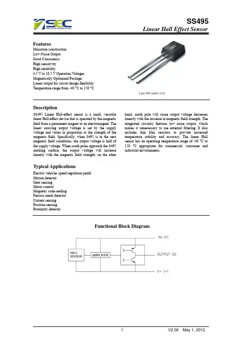


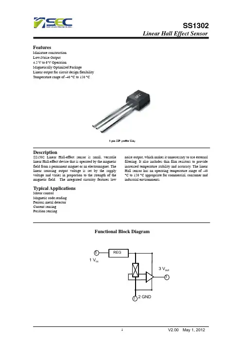
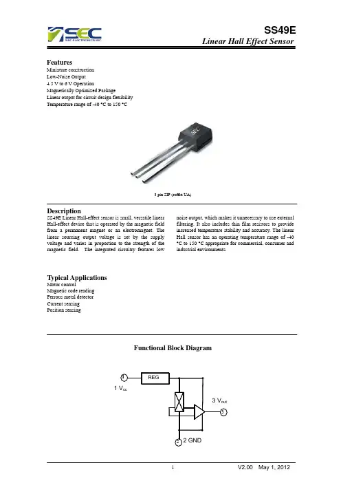
3 pin SIP (suffix UA) DescriptionSS1302 Linear Hall-effect sensor is small, versatile linear Hall-effect device that is operated by the magnetic field from a permanent magnet or an electromagnet. The linear sourcing output voltage is set by the supply voltage and varies in proportion to the strength of the magnetic field. The integrated circuitry features low noise output, which makes it unnecessary to use external filtering. It also includes thin film resistors to provide increased temperature stability and accuracy. The linear Hall sensor has an operating temperature range of -40 °C to 150 °C appropriate for commercial, consumer and industrial environments.Typical ApplicationsMotor controlMagnetic code readingFerrous metal detectorCurrent sensingPosition sensingFunctional Block DiagramPins DefinitionPin DescriptionAbsolute Maximum RatingsParameterSymbolValueUnitsSupply V oltage (operating) V CC 8.0 V Output CurrentI OUT 20 mA Operating Temperature Range T A -40~150 ℃ Storage Temperature RangT S -65~150℃Electrical Characteristics(TA =25℃,VCC =5.0V)TypUnitsMinMaxTestParameter SymbolConditionsV Operating voltage V CC Operating 3.0 6.5mA8.0Supply current I CC Average 4.21.5 mA Output Current I OUT 1.0Response Time T ack 3 uS Quiescent Output V oltage V o B=0G 2.25 2.5 2.75 V2.0mV/G1.8Sensitivity △V out T A=25℃ 1.6Min Output V oltage B=-1500G 0.86 VMax Output V oltage B=1500G 4.21 V Performance Characteristics输出电压与磁场强度曲线静态输出电压与工作电压关系曲线Package InformationPackage UA, 3-Pin SIP:Ordering InformationPart No. Pb-free Temperature Code Package Code PackingSS1302EUA YES -40°C to 150°C TO-92 Bulk, 1000 pieces/bag SS1302KUA YES -40°C to 125°C TO-92 Bulk, 1000 pieces/bag SS1302LUA YES -40°C to 150°C TO-92 Bulk, 1000 pieces/bag。
PLA 90Counter LoopMAN 173DWe would like to congratulate you on purchasing your portable induction loop system PLA 90. Y ou have chosen a modern, reliable device. Please read these operating instructions carefully. This describes how to set up the system correctly and explains all the system features. Standard componentsPlease check if all following components are included:- Portable induction loop system PLA 90 with integrated battery,- Power supply unit- 3 color signal strips- 2 T-coil labels- 4 rubber feet- Operating instructions- Warranty cardIf any parts are missing, please contact your dealer immediately.How it worksThe PLA 90 uses its built-in microphone or an external microphone to pick up sounds and emits them via the integrated induction loop. The signals emitted in this way can be received by a hearing aid that is set to the “T” or “MT” position.Setting up the PLA 90The induction loop system is already completely installed and set up in the housing. All you have to do is to place the PLA 90 at the desired position between you and the person you are talking to and connect the power supply unit. Please note that the microphone on the back of the device should be facing the person speaking.Switching the device onT o switch the induction loop system on, press the “Power on“ button on the rear side of the device. Once the device is switched on, the “Power on” light on the rear of the device will light up green, and the “Power on” light on the front will light up blue.Picking up/ emitting signalsIf sounds are picked up by the microphone on the back of the device or via an external microphone and emitted by the device as magnetic signals, the status light “loop signal” will flash orange.Controls and IndicatorsColor signal stripFront Viewjack microphone input jack Built-in microphone Microphone adjustment Volume control Microphone selection switch (internal/external)Theft protection via Kensington™lockRear ViewAdditional microphone input(3.5 mm plug)An external microphone can be connected to the additional microphone input.Microphone selection switchWith the microphone selection switch you can choose the microphone which should record the sounds.Switch position:Up: internal microphoneDown: external microphoneSetting the sensitivity of the microphone inputWith the control dial on the backside of the device you can adjust the sensitivity of the microphone input. This is useful if you want to connect a low-output microphone to the PLA 90.Headphone jack (3.5 mm plug)Y ou can connect the following products to the Headphone jack:- Under-the-chin receiver- Unobtrusive earphones- Lightweight headset- Audio-Cable monaural- Audio-Cable binaural- Induction Link monaural- Induction Link binauralVolume controlThe volume control adjusts the volume of the headphone jack. Automatic switch offThe PLA 90 will switch off automatically after 2 minutes if no signal is received, from either the internal or external microphone.Charging control lightLED flashes red = Battery is in the process of being rechargedLED off = Battery is fully rechargedPermanent installation of the PLA 90The PLA 90 can be screw-fastened through the lateral holes to a tabletop or other surfaces. The holes are located under the side covers. Remove the covers as shown in the picture below.Retaining clipSide cover Holes for screw fasteningSwitching the device offT o switch the induction loop system off, press the “Power off” button on the rear side of the device. The “Power on” control light goes off.Power supply for the PLA 90The PLA 90 can be operated using the built-in rechargeable battery or the power supply unit. If the battery is fully charged, the device can be used for up to 6 hours.A depleted battery has to be recharged for approximately 3 hours until it reaches full capacity again. Y ou can also use thePLA 90 while it is being charged, but please note that this will lengthen the time required to fully recharge the battery. The device can remain connected to the power supply for as long as desiredWall mounting1. Screw in two screws (not included)14.1 cm apart at the place you would like to mount the PLA 90 on the wall (see figure).2. Now set the PLA 90 on the screws and slide it down slightly to secure it in place.5.55 inChanging the color signal stripY ou can change the color signal strip of the PLA 90, as shown below.Maintenance and careThe PLA 90 does not require any maintenance. If the unit becomes dirty, simply wipe it clean with a soft, damp cloth. Never use spirits, thinners or other organic solvents. Do not set up the unit where it will be exposedto full sunlight for long periods. In addition it must be protected against excessive heat, moisture and severe mechanical shock. Note: This product is not protected against splash water. Do not place any containers filled with water, such as flower vases, or anything with an open flame, such as a lit candle, on or near the product.SpecificationsDimensions:7-7/8" H x 7-1/4" W x 2-15/16" D(200 x 185 x 70 mm)Weight: 1.4 lb (635 g) (with battery installed)Power supply:Input: 100-240 VAC, 50-60 HzOutput: 16 VDCRechargeable battery:12 V NiMH, user-replaceable.Operating time per charge:Up to 6 hoursBattery charging time:Approximately 3 hoursOutput power:10 WMicrophone Sensitivity:Up to 60 dB ±3 dBCE Certification (EU directives):2002/95/EG RoHS 2002/96/EG WEEE 2004/108/EG EMC 2006/95/EG Low voltageCompliance with the directives listed above is confirmed by the CE seal on the device. Specifications subject to change without notice.WarrantyThe PLA 90 is a very reliable product. Should a malfunction occur despite the unit having been set up and operated correctly, please contact your dealer.The warranty covers the repair of the product and returning it to you free of charge during the warranty period. It is essential that you send in the product in its original packaging, so do not throw the packaging away. The warranty does not apply to damage caused by incorrect handling or attempts to repair the unit by people not authorized to do so (destruction of the seal on the unit). Repairs under warranty are only carried out providing the enclosed warranty card is filled out and returned to dealer; also a copy of the sales slip is required.Unit disposalDisposal of used electric and electronic units (applicable in thecountries of the European Union and other European countrieswith a separate collection system). The symbol on the productor the packaging indicates that this product is not to be handledas ordinary household waste but has to be returned to a collecting point for the recycling of electric and electronic units. Y ou protect health and environment by the correct disposal of this product. Material recycling helps to reduce the consumption of raw material. Y ou will receive further information on the recycling of this product from your local community, your communal disposal company or your local dealer.Rechargeable battery disposalThe rechargeable battery that comes with the device can berecycled.Please dispose of this rechargeable battery in receptaclesdesigned for that purpose or return it to a retail outlet. Disposeonly of those batteries that have been completely discharged toensure environmental protection.*******************/ 800-843-3544 / INTL: +1-952-943-2252©2019 Williams AV • All Rights Reserved MAN 173D。
目录一.继电器介绍、定货选型和安装 (3)1.介绍 (3)2. 定货选型 (4)3.继电器安装 (7)二.继电器元件与功能 (8)三.面板按钮操作 (8)1.概述 (8)2.通过前面板修改显示定值 (9)3.通过前面板观察继电器内部字位 (10)4.通过前面板在液晶中显示表计数据 (10)5.通过前面板在液晶中显示事故报告摘要 (11)6.初始状态下的液晶显示 (11)7.改变当前运行定值组 (11)8.前面板上其它功能键 (11)四.串口通信和命令 (11)1.串口通信 (11)2.串口命令 (12)3.SEL-351继电器串口命令摘要 (14)BRE命令(断路器监视数据) (14)COMM命令(通讯数据) (14)DAT命令(查看/改变日期) (16)EVE命令(事件) (16)GRO命令(显示运行整定值组号) (16)HIS命令(事件摘要/历史) (16)IRI命令(与IRIG-B时间码同步) (17)LDP命令(负荷存档报告) (18)MET命令(表计数据) (18)MET k-瞬时量表计 (18)MET D-需求量表计 (19)MET E-能量表计 (19)MET E-能量表计 (20)QUI命令(退出命令处理层) (20)SER命令(顺序事件记录器报告) (20)SHO命令(显示/查看整定值) (21)STA命令(继电器自检状态) (24)STA命令行和列定义 (24)TAR命令(显示继电器元件状态) (25)继电器字位(用于SELogic控制方程) (25)TIM命令(查看/改变时间) (28)TRI命令(触发事件报告) (28)命令处理层B命令 (28)BRE n命令(预载/复归断路器损耗) (28)CLO命令(闭合断路器) (29)GRO n命令(改变运行整定值组) (29)OPE命令(打开断路器) (30)PUL命令(脉冲输出接点) (30)命令处理层2命令 (30)CON命令(控制远方位) (30)COP m n命令(拷贝整定值组) (31)LOO命令(闭环检测) (31)PAS命令(查看/改变口令) (32)SET命令(改变整定值) (32)五.跳闸和信号逻辑 (32)附录A. 整定单附录B. 继电器保护逻辑一.继电器介绍、定货选型和安装1.介绍主要特性和优点SEL-351继电器是一种集保护、监视、控制和故障定位于一体的保护装置。
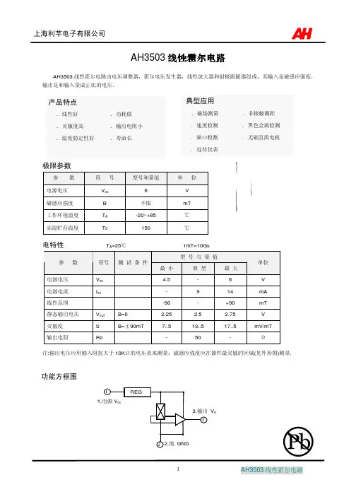
霍尔元件技术指标1相关参数1.1封装形式TO—92(三脚插片),SOT-23(三脚贴片)。
还有SIP-4(四脚插片),SOT-143(四脚贴片)与SOT-89(四脚贴片)1。
2电源有3、5~24V,2。
5~3。
5V,2、5~5V1。
3灵敏度Kh 数量级在,且数值越大灵敏度越高1.4霍尔电势温度越小,设备精确度越大(必要时可以增加温度补偿电路)1。
5额定控制电流一般在几mA~几十mA,尺寸越大其值越大(尺寸大得可达几百mA)1。
6型号开关型得、线性得、单极性得、双极性得。
双极开关霍尔元件:177A、177B、177C单极霍尔开关元件:AH175、732、1881、S41、SH12AF、3144、44E、3021、137、AH137、AH284线性霍尔元件:3503、S496B、49E锁定霍尔元件:ATS175、AH173、SS413A、3172、3075互补双输出开关霍尔元件:276A、276B、276C、277A、277B、277C信号霍尔元件:211A、211B、211C微功耗霍尔元件:TEL4913、TP4913、A3212、A3211。
(具体霍尔开关元件见附录)ﻫ1.7输入电阻与输出电阻一般在几Ω到几百Ω,且输入电阻要大于输出电阻1。
8外接上拉电阻一般大于1KΩ、对一般TTL电路,由于其高电平电压较低,用于驱动CMOS电路时,增加上拉电阻,可以提高其高电平得电压。
常用得阻值就是4.7k或10k。
上拉电阻得就是接在1脚电源Vcc与3脚信号输出Vout之间。
1。
9功能分类按照霍尔器件得功能可将它们分为:霍尔线性器件与霍尔开关器件。
前者输出模拟量,后者输出数字量。
都就是输出高电平脉冲信号,不同得就是开关型相当于到GS设定值时电平反转;线性得可能就是电压逐渐变化,到一定时使后处理电路输出反电平、一般建议用线性得,开关型常因为温度等原因使得设定值漂移,导致灵敏度下降。
1、10霍尔工作点霍尔得工作点一般在:单极开关60到200,双极锁定在100内(单位GS)、1、11霍尔工作频率一般霍尔得工作频率在100KHZ以上1、12输出幅值由具体型号及供电电源决定,一般来讲,输出幅度比供电电源略低、1、13输出方波延迟时间经过霍尔器件得信号在上升时有一定延迟,取上升10%到90%得时间段作为参考,一般在ms数量级。
目录第三部分:过电流、电压、同期检测、频率和功率元件 .............................. 3-1 瞬时/定时限过电流元件.................................................................................................................. 3-1 相瞬时/定时限过电流元件....................................................................................................... 3-1 整定范围............................................................................................................................. 3-1 精度..................................................................................................................................... 3-1 动作行为............................................................................................................................. 3-1 方向控制选项..................................................................................................................... 3-1 控制..................................................................................................................................... 3-2 复合单相瞬时过电流元件................................................................................................. 3-2 动作和复归时间曲线......................................................................................................... 3-3 相间瞬时过电流元件................................................................................................................ 3-3 整定范围............................................................................................................................. 3-3 精度..................................................................................................................................... 3-3 动作行为............................................................................................................................. 3-3 动作和复归曲线................................................................................................................. 3-3 中性点接地瞬时/定时限过电流元件....................................................................................... 3-3 整定范围............................................................................................................................. 3-4 精度..................................................................................................................................... 3-4 动作和返回时间曲线......................................................................................................... 3-4 零序接地瞬时/定时限过电流元件........................................................................................... 3-4 整定范围............................................................................................................................. 3-4 精度..................................................................................................................................... 3-4 动作和复归时间曲线......................................................................................................... 3-5 负序瞬时/定时限过电流元件................................................................................................... 3-5 整定范围............................................................................................................................. 3-5 精度..................................................................................................................................... 3-5 动作和复归时间曲线......................................................................................................... 3-5 反时限过电流元件........................................................................................................................... 3-5 相反时限过电流元件................................................................................................................ 3-5 整定范围(51PT元件举例) ........................................................................................... 3-6 精度..................................................................................................................................... 3-6 逻辑输出(51PT元件举例) ........................................................................................... 3-6 控制开关动作行为(51PT元件举例) ........................................................................... 3-7逻辑点TCP的控制 ........................................................................................................... 3-7 方向控制选项..................................................................................................................... 3-7 控制..................................................................................................................................... 3-8 复归计时细则(51PT元件举例) ................................................................................... 3-8 整定值51PRS=Y ............................................................................................................... 3-8 整定值51PRS=N ............................................................................................................... 3-8 单相反时限过电流元件的动作行为(51AT、51BT、51CT) ..................................... 3-9 中性点接地反时限过电流元件................................................................................................ 3-9 整定范围........................................................................................................................... 3-10 精度................................................................................................................................... 3-10 零序接地反时限过电流元件.................................................................................................. 3-10 整定范围........................................................................................................................... 3-10 精度................................................................................................................................... 3-11 负序反时限过电流元件.......................................................................................................... 3-11 整定范围........................................................................................................................... 3-11 精度................................................................................................................................... 3-11 电压元件......................................................................................................................................... 3-11 电压量值.................................................................................................................................. 3-12 电压元件整定值...................................................................................................................... 3-12 精度................................................................................................................................... 3-14 电压元件动作行为.................................................................................................................. 3-14 低电压元件动作行为举例............................................................................................... 3-14 过电压元件动作行为举例............................................................................................... 3-14 用于POTT逻辑的电压元件.................................................................................................. 3-14 同期检测元件................................................................................................................................. 3-15 同期检测元件整定值.............................................................................................................. 3-15 精度................................................................................................................................... 3-16 同期检测元件电压输入.......................................................................................................... 3-16 系统频率由电压输入VA(或VAB对于三角形)和VS决定................................... 3-16 同期检测元件的动作行为...................................................................................................... 3-16 电压窗口........................................................................................................................... 3-16 电压窗口元件的其它用途............................................................................................... 3-17角度差计算器................................................................................................................... 3-18 电压Vp和Vs是“静态的”.......................................................................................... 3-18 电压Vp和Vs是“滑动的”.......................................................................................... 3-18 角度差举例(电压Vp和Vs是“滑动的”).............................................................. 3-18 同期检测元件输出........................................................................................................... 3-19 电压Vp和Vs是“静态的”.......................................................................................... 3-19 电压Vp和Vs是“滑动的”.......................................................................................... 3-19 自动重合闸和手动重合闸的同期检测应用.......................................................................... 3-20 频率元件......................................................................................................................................... 3-20 频率元件整定值...................................................................................................................... 3-20 精度................................................................................................................................... 3-20 产生过频和低频元件....................................................................................................... 3-21 过频元件........................................................................................................................... 3-21 低频元件........................................................................................................................... 3-21 频率元件动作行为.................................................................................................................. 3-21 过频元件动作行为........................................................................................................... 3-21 低频元件动作行为........................................................................................................... 3-21 频率元件电压控制........................................................................................................... 3-22 低电压元件27B81的其它用途 ...................................................................................... 3-22 频率元件的使用...................................................................................................................... 3-22 功率元件(仅仅适用于版本2以上的固件)............................................................................. 3-22 功率元件整定值...................................................................................................................... 3-22 精度.......................................................................................................................................... 3-23 功率元件逻辑操作.................................................................................................................. 3-23 功率元件应用-电容器组的VAR控制 .................................................................................. 3-24表格表格3.2:相反时限过电流元件(最大相)整定值..................................................................... 3-6 表格3.3:相反时限过电流元件(最大相)逻辑输出................................................................. 3-6 表格3.4:中性点接地反时限过电流元件整定值....................................................................... 3-10 表格3.5:零序接地反时限过电流元件整定值........................................................................... 3-10 表格3.6:负序反时限过电流元件整定值................................................................................... 3-11 表格3.7:电压元件使用的电压量............................................................................................... 3-12表格3.8:电压元件整定值和整定范围(星型连接电压)....................................................... 3-12 表格3.9:电压元件整定值和整定范围(三角形连接电压)................................................... 3-13 表格3.10:同期检测元件整定值和整定范围............................................................................. 3-15 表格3.11:频率元件整定值和整定范围..................................................................................... 3-20 表格3.12:功率元件整定值和整定值范围................................................................................. 3-22图形图3.1:1到4段相瞬时过电流元件 .............................................................................................. 3-1 图3.2:5到6段相瞬时过电流元件 .............................................................................................. 3-1 图3.3:1到4相瞬时/定时限过电流元件(具有方向控制选项)............................................. 3-1 图3.4:复合单相瞬时过电流元件................................................................................................. 3-2 图3.5:SEL-351继电器无方向瞬时过电流元件动作时间曲线 ................................................. 3-3 图3.6:SEL-351继电器无方向瞬时过电流元件复归时间曲线 ................................................. 3-3 图3.7:1到4段相间瞬时过电流元件 .......................................................................................... 3-4 图3.8:1到4段中性点接地瞬时/定时限过电流元件(具有方向控制选项)......................... 3-4 图3.9:5到6段中性点接地瞬时/定时限过电流元件................................................................. 3-4 图3.10:1到4段零序接地瞬时/定时限过电流元件(具有方向控制选项)........................... 3-4 图3.11:5到6段零序接地瞬时/定时限过电流元件................................................................... 3-4 图3.12:1到4段负序瞬时/定时限过电流元件(具有方向控制选项)................................... 3-5 图3.13:5到6段负序瞬时/定时限过电流元件........................................................................... 3-5 图3.14:相反时限过电流元件51PT(具有方向控制选项)..................................................... 3-6 图3.15:A相反时限过电流元件51AT(具有方向选项)......................................................... 3-9 图3.16:B相反时限过电流元件51BT(具有方向选项) ......................................................... 3-9 图3.17:C相反时限过电流元件51CT(具有方向选项) ......................................................... 3-9 图3.18:中性点接地反时限过电流元件51NT(具有方向选项) ............................................ 3-9 图3.19:零序接地反时限过电流元件51GT(具有方向控制选项) ...................................... 3-10 图3.20:负序反时限过电流元件51QT(具有方向控制选项) .............................................. 3-11 图3.21:单相和三相电压元件(星型连接电压)..................................................................... 3-13 图3.22:相间和序电压元件(星型连接电压)......................................................................... 3-13 图3.23:相间电压元件(三角形连接电压)............................................................................. 3-14 图3.24:序电压元件(三角形连接电压)................................................................................. 3-14 图3.25:通道VS电压元件(星型或三角形连接电压).......................................................... 3-14 图3.26:同期检测电压窗口和转差频率元件............................................................................. 3-16 图3.27:同期检测元件................................................................................................................. 3-16 图3.28:经过断路器合闸时间补偿的Vp和Vs间角度差(举例中fp<fs,Vp为参照量).3-18图3.29:用于频率元件的低电压闭锁......................................................................................... 3-20 图3.30:1到6段频率元件 .......................................................................................................... 3-20 图3.31:功率元件逻辑(+VARS举例)................................................................................... 3-23 图3.32:功率元件在有功/无功功率平面中的操作.................................................................... 3-23 图3.33:SEL-351(B)继电器提供9600kVAR电容器组的VAR控制 ................................. 3-24 图3.34:用于切换9600kVAR电容器组投入和退出控制的每单元整定值限制 .................... 3-24第三部分:过电流、电压、同期检测、频率和功率元件瞬时/定时限过电流元件相瞬时/定时限过电流元件共有四段相瞬时/定时限过电流元件。
金属检测系统的设计与研究摘要:以C8051F350单片机为核心,利用线性霍尔传感器CS3503测试了金属在通电线圈磁场改变过程中的作用,以及转换成电压的改变,然后对霍尔传感器测得的微弱电压放大,峰值检波,将输出电压信号输入单片机,实现内部A/D转换,并且和单片机内预设定值作了对比,由此判定金属为危险品,然后确定报警与否。
关键词:金属探测仪;线性霍尔元件;电磁感应;灵敏度0前言金属探测仪就是对金属进行专门检测的设备,作为检测的重要设备,它已在社会生活,工业生产等许多领域中得到了广泛的应用。
随着科学技术水平的不断提高,对其提出了更高要求,因此,金属探测器也得到越来越多研究人员的重视。
由于金属探测器响应快、尺寸小,使用方便的优点,在多种用途上深受人们的青眯。
以便能对金属物体进行精确的探测,便要求金属探测器可靠性高,探测精度高。
针对这一问题,提出了一种基于磁阻式位移传感原理的新型金属探测系统设计方法。
使用极高线性霍尔元件做传感器,感应金属在通电线圈中磁场的改变,从而提高了检测精度;处理模块采用单片机C8051F350为核心,对接收模块输出信号进行处理并分析和判断,有效地确保金属检测得以实施。
1 总体设计本设计的总体设计方案如图1所示。
整个金属检测系统由三个部分组成:(1)金属探测模块。
该模块包括高频逆变电路,谐振电路;(2)数据采集模块。
该模块包括CS3503线性霍尔传感元件,放大电路,峰值检波电路;(3)软件设计部分。
将霍尔器件固定于电感线圈中央,可以检测线圈磁场是否发生变化,以及转换成电压信号。
当有某一种或几种金属棒穿过时该传感器就会发出一个电信号。
在没有金属穿过的情况下,输出信号是一个固定值而不会发出警报;当金属物进入磁力线中或被磁化时则输出一定频率的电信号,经过放大、滤波等预处理后送入单片机系统,对该信号强度大小及波形进行分析处理,以确定是否存在金属。
金属被探测出来之后,霍尔元件依据磁场的变化而转换成电压信号,经放大,峰值检波,输出稳定峰值通过单片机内A/D转换,并与单片机内预设值运算对比,用它来判定金属是否存在。
3 pin SIP (suffix UA) Description
SS3503 Linear Hall-effect sensor is small, versatile linear Hall-effect device that is operated by the magnetic field from a permanent magnet or an electromagnet. The linear sourcing output voltage is set by the supply voltage and varies in proportion to the strength of the magnetic field. The integrated circuitry features low noise output, which makes it unnecessary to use external filtering. It also includes thin film resistors to provide increased temperature stability and accuracy. The linear Hall sensor has an operating temperature range of -40 °C to 150 °C appropriate for commercial, consumer and industrial environments.
Typical Applications
Motor control
Magnetic code reading
Ferrous metal detector
Current sensing
Position sensing
Functional Block Diagram
Pins Definition
Pin Description
Absolute Maximum Ratings
Parameter
Symbol
Value
Units
Supply V oltage (operating) V CC 8.0 V Output Current
I OUT 20 mA Operating Temperature Range T A -40~150 ℃ Storage Temperature Rang
T S -65~150
℃
Electrical Characteristics(TA =25℃,VCC =5.0V)
Typ
Units
Min
Max
Test
Parameter Symbol
Conditions
V Operating voltage V CC Operating 3.0 6.5
mA
8.0
Supply current I CC Average 4.2
1.5 mA Output Current I OUT 1.0
Response Time T ack 3 uS Quiescent Output V oltage V o B=0G 2.25 2.5 2.75 V
2.0
mV/G
1.8
Sensitivity △V out T A=25℃ 1.6
Min Output V oltage B=-1500G 0.86 V
Max Output V oltage B=1500G 4.21 V Performance Characteristics
输出电压与磁场强度曲线静态输出电压与工作电压关系曲线
Package Information
Package UA, 3-Pin SIP:
Ordering Information
Part No. Pb-free Temperature Code Package Code Packing
SS3503EUA YES -40°C to 85°C TO-92 Bulk, 1000 pieces/bag SS3503KUA YES -40°C to 125°C TO-92 Bulk, 1000 pieces/bag SS3503LUA YES -40°C to 150°C TO-92 Bulk, 1000 pieces/bag。