EUCHNER使用说明书
- 格式:pdf
- 大小:3.44 MB
- 文档页数:36
精密组合行程开关质量-安士能制造精密组合行程开关概要外置防污隔膜柱塞互换式导块精密组合行程开关RGBF..12/16… 系列依据DIN 43697的立式壳体柱塞间距12与16mmSN..12/16… 系列立式壳体,小型安装底座柱塞间距12与16mmSN/SB…08… 系列立式壳体,无安装底座柱塞间距8mmGSBF..12/16… 系列立式壳体柱塞间距12与16mmGSBF..08… 系列立式壳体柱塞间距8mmGLBF..12/16… 系列卧式壳体柱塞间距12与16mmGLBF..08… 系列卧式壳体柱塞间距8mmRGBF/SN…AM 系列立式壳体,外置防污隔膜柱塞间距12mmRGCS 系列立式壳体,依据DIN 43697;带柱塞互换式导块柱塞间距12mmLED功能显示防水电缆接头开关元件附 件附 录柱塞开关元件可定制的产品相关产品目 录高精度、高可靠性是该产品的主要特征。
此外,它还有以下优点:概 要应 用安士能公司的精密组合行程开关应用于所有机械、系统工程和自动化机构中需要精确定位和管理的领域。
紧凑型的设计使其适应最小的空间位置要求。
常规的电缆接线,成本低。
触点有序而集中,易于检测和维护。
安装方便。
包括DIN标准型在内的齐备的壳体外型,满足了各种应用场合。
IP67的防护等级保证了该产品在任何安装位置的优越品质的表现。
功 能精密组合行程开关采用多个开关元件并行排列的方式,相邻开关元件之间的间距依据DIN43697标准有12mm和16mm两种,此外还有间距8mm的产品,该产品设计特别紧凑,安装空间更小。
开关元件通过柱塞来触发,配合符合DIN69639标准的挡块来完成定位控制,挡块通常与符合DIN69638标准的导轨一起使用。
(详见样本《挡块与导轨》)设 计根据技术要求的不同,如重复定位精度和接近速度,柱塞有四种不同的形式可供选择(楔型、滚轮型、拱型和球型)。
根据不同的柱塞形式,重复定位精度最高可控制在±0.002mm的范围内,最高接近速度可达120m/min。
Connection of CET1-AR to a Safety Relay MSR127TPContentGuard locking spring applied − power on released according to EN ISO 14119 (closed-circuit current principle) (2)Components/modules used (2)EUCHNER (2)Other (2)Functional description (3)General (3)Connections (3)Safety assessment (3)Principle circuit diagram (4)Settings of the Reset for MSR127TP (5)Manual Reset (5)Automatic Reset (5)Important note – please observe carefully! (6)Guard locking spring applied − power on released according to EN ISO 14119 (closed-circuit current principle)Safety function Guard locking for personal protection according to EN ISO 14119 Reliability figures according to EN ISO 13849 Category 4, PL eComponents/modules usedEUCHNERDescription Order no./item designationSafety switches with guard locking and guard locking monitoring with transponder technology 103418 / CET1-AR-CRA-AH-50X-SG-103418 106159 / CET1-AR-CRA-AH-50F-SG-106159 106275 / CET1-AR-CDA-AH-50X-SG-106275Tip: More information and downloads about the above mentioned EUCHNER products can be found at www.EUCHNER.de. Simply enter the order number into the search field.OtherDescription ItemsSafety relay MSR127TP / 440R-N23132Functional descriptionGeneralThe CET1 is a guard locking device according to EN ISO 14119 using the closed-circuit current principle. The two safe outputs of the CET1 are connected to a MSR127TP safety relay.ConnectionsDesignation Function Use in this exampleOA, OB Safety outputs. HIGH when the safety guard isclosed and locked. Switch-off of at least one of the outputs leads to a direct switch-off of the safety contacts (13 – 14, 23 – 24, …) of the safety relay MSR127TP.Important: The actual shutdown of the energy which is causing a hazard in a machine is not shown in the example and must be supplemented.IA, IB Inputs for series connection of AR devices fromEUCHNERConnected to 24 V DC; function is not used.+UCM, 0V (UCM) Control input for guard locking solenoid. Connectguard locking to 24 V DC to open.Activated by switch S1.Important: According to EN ISO 14119, it shall be ensuredthat the hazard caused by a machine has disappearedbefore the guard locking can be released.OUT Monitoring output. HIGH when outputs OA and OBare switched on (safety guard closed and locked).Function is not usedLED1 Input for controlling the installed red LED. Function is not used.LED2 Input for controlling the installed green LED. Function is not used.RST Input for resetting the switch Connected to ground; function is not used.J Teach-in input The corresponding input must be connected to 24 V DC foractuator teach-in (for this purpose, see the operatinginstructions1)).Important: for teach-in operation terminal 0V (UCM) has tobe connected to 0V not to a different potential or to anoutput.The input must be unconnected during operation.1) You can find the current operating instructions on the Internet at www.euchner.de. Simply enter the order number into the search field.Safety assessmentThe CET1 features complete monitoring for faults in the safety-relevant parts and in the connected cables (clock pulses at outputs OA and OB). The safety relay MSR127TP achieve up to PL e according to the manufacturer’s information (see the device’s operating instructions for this purpose). The wiring is similar to the circuit “Light Curtain, Monitored Manual Reset, Monitored Output” in the operating instructions of the MSR127TP. As found in the operation manual of the MSR127TP, when connected to light curtains, the light curtain must perform cross fault detection (here CET1), then, the wiring corresponds to PL e. Therefore, PL e in accordance with EN ISO 13849-1 can be achieved for locking mechanism position monitoring of guard locking of the CET1.A safety assessment for control of guard locking is not part of this example and must be supplemented for the respective machine by the design engineer in accordance with the risk assessment.Important: Switch-off of the energy and any necessary monitoring energy switch-off (feedback loop) of the hazard are not part of this document and must be added in accordance with the risk assessment for the machine. In this example, the safety evaluation unit without feedback loop and with start button is used. Please refer to the operating instructions of the safety evaluation unit used for more information.Principle circuit diagramIn the example Manual Restart of the MSR127TP is used.Figure 1Settings of the Reset for MSR127TPOnly with the following settings does the Safety Relay MSR127TP operate correctly with a CET1-AR. Manual ResetAutomatic ResetImportant note – please observe carefully!This document is intended for a design engineer who possesses the requisite knowledge in safety engineering and knows the applicable standards, e.g. through training for qualification as a safety engineer. Only with the appropriate qualification is it possible to integrate the introduced example into a complete safety chain.The example represents only a part of a complete safety chain and does not fulfill any safety function on its own. In order to fulfill a safety function, the energy switch-off function for the hazard location and the software within the safety evaluation must also be considered, for example.The introduced applications are only examples for solving certain safety tasks for protecting safety guards. The examples cannot be comprehensive due to the application-dependent and individual protection goals within a machine/installation.If questions pertaining to this example remain open, please contact us directly.In accordance with Machinery Directive 2006/42/EC, the design engineer of a machine or installation is obligated to perform a risk assessment and take measures to reduce the risk. When doing this, the engineer must comply with the applicable national and international standards. Standards generally represent the current state of the art. Therefore, the design engineer should continuously inform himself about changes in the standards and adapt his considerations to them. Relevant standards include EN ISO 13849 and EN 62061. This application must be regarded only as assistance for the considerations about safety measures. The design engineer of a machine/installation is obligated to assess the safety technology himself. The examples must not be used for assessment, because only a small excerpt of a complete safety function was considered in terms of safety engineering here. In order to be able to use the safety switch applications correctly on safety guards, it is indispensable to observe the standards EN ISO 13849-1, EN ISO 14119 and all relevant C-standards for the respective machine type. Under no circumstances does this document replace the engineer’s own risk assessment, and it cannot serve as the basis for a fault assessment.Particularly in case of a fault exclusion, it must be noted that this can be performed only by the design engineer of a machine or installation and requires a reason. A general fault exclusion is not possible. More information about fault exclusion can be found in EN ISO 13849-2.Changes at products or within assemblies from third-party suppliers used in this example can lead to the function no longer being ensured or the safety assessment having to be adapted. In any event, the information in the operating instructions on the part of EUCHNER, as well as on the part of third-party suppliers, must be taken as the basis before this application is integrated into an overall safety function. If contradictions should arise between the operating instructions and this document, please contact us directly.Use of brand and company namesAll mentioned brand and company names are property of the respective manufacturers. The use is only for clear identification of compatible peripheral devices and environment of operation in combination with our products.EUCHNER GmbH + Co. KG · Kohlhammerstraße 16 · 70771 Leinfelden-EchterdingenTelefon:+497117597-0·Telefax:+497117597-303·***************·www.euchner.de。
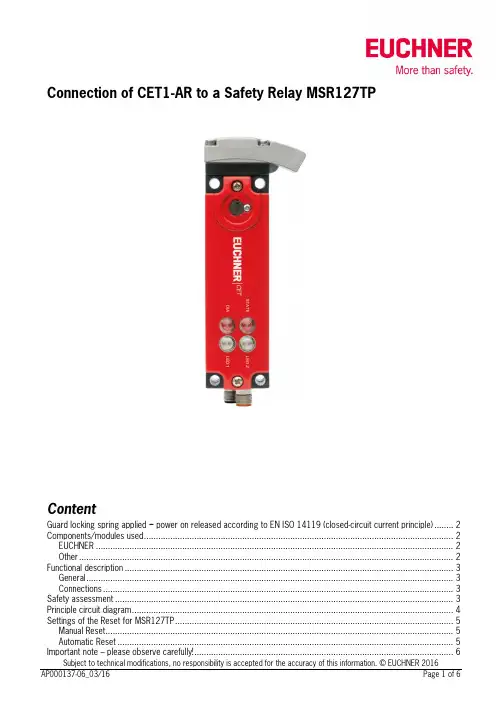
Read head CET-AX-...Read head with guard locking and guard lock monitoring Up to category 4High locking forces up to 6500 N Integrated transponder coding Metal housingDesign and functionalityWith the read head CET, EUCHNER provides monitored guard locking based on non-contact transponder technology. This means that the switch can also be used on systems with overtravelling machine movements for the personal protection.When closing the safety guard (hinged or sliding door), the spring-loaded transponder in the actuator is inserted into the recess on the read head.The read head detects the closed safety guard in its guard locked posi-tion. The CES evaluation electronics enables the safety circuit when the safety guard is locked.When the moving parts of the machine come to a standstill, the solenoid integrated into the read head can be activated by a safe standstill monitor or by a timer relay. The solenoid's plunger then raises the spring-loaded transponder, which allows the safety guard to be opened.Use of the read head even in extremely harsh environmentsDue to the extremely robust metal housing, the switch is suitable for the harshest ambient conditions and when guard locked achieves a locking force of 6500 N - a characteristic that is advantageous particularly for heavy doors.With the safety guard closed, the CET provides around ± 5 mm of freedom of movement in all 3 directions (x, y, z direction) - even if the safety guard drops over time it will not be necessary to re-adjust the actuator.The insertion slide can be rotated in 90° steps. As a result the switch is suitable for doors hinged on the right and left.Different versionsAlong with the standard version with a single insertion slide, there is also the CET with a double insertion slide that is perfectly suited to swing doors and rotary tables. That is, wherever the approach is from two sides and where the read head must also be "passed over".As an option, EUCHNER also offers versions with escape release. This feature enables people locked in to open the locked safety guard from the inside in an emergency.The range is supplemented by versions with different plug variants and freely configurable LED control.f f f f fY our advantagesRobust die-cast zinc housing for harsh environments Suitable for heavy doorsHigh protection against tampering Actuator with large freedom of movement No precise door adjustment necessary Low wiring effortHigh degree of protection IP67Suitable for the highest safety requirementsf f f f f f f fApproach directionHorizontalCan be adjusted in 90° steps Mechanical releaseIs used for releasing the guard locking with the aid of a tool. The mechanical release must be sealed to prevent tampering (for example with sealing lacquer).Escape release (optional)Is used for the manual release of the guard lock-ing from within the danger area without tools. Solenoid operating voltage DC 24 V +10%, -15%Guard locking typesCET1Closed-circuit current principle Release by applying voltage to the interlocking solenoid.CET2Open-circuit current principle Guard locking by applying voltage to the interlocking solenoid. Release by spring force.LED function display LED red illuminates when solenoid switchedon or freely configurableLED green freelyconfigurable Category in accordance with EN ISO 13849-1The category in accordance with EN ISO 13849-1 is dependent on the evaluation unit used and on the installation position (see possible combina-tions on page 63).NotesSpecial EUCHNER connection cables are re-quired for the connection (see page 65/66/68). Please take into account in the order!The read head CE T is only allowed to be operated in conjunction with the actuator CET-A-BWK-50X. The actuator must be ordered separately.ff f ff f f Read head CET...With plug connector M 12For possible combinations see page 63Read head CET...with escape release Read head CET...with 2 plug connectors M8Read head with guard locking Locking force up to 6500 NUp to category 4 / PL e according to EN ISO 13849-1f f f Ordering table see page 62.* Only for standard EUCHNER connection cable Ordering table1) Plug connector can be rotated by 360°.Technical data read head CET...Important:The maximum safety category that can be achieved in accordance with EN ISO 13849-1 is dependent on the installation position of the safety switch and the evaluation unit used. Pay attention to the table below during the selection of the evaluation unit.Possible combinations。
ZH使用说明书安全系统MGB-L0…-AR.-…MGB-L0…-AP.-…V3.0.0以上使用说明书 安全系统MGB-L0…-AR.-…和MGB-L0…-AP.-…内容1. 关于本文件 (4)1.1. 适用性 (4)1.1.1. 关于旧产品版本的提示 (4)1.2. 目标群体 (4)1.3. 符号说明 (4)1.4. 补充文件 (5)2. 正确的使用方法 (6)2.1. MGB-AP和MGB-AR的主要区别 (7)3. 安全功能说明 (8)4. 免责和质保 (9)5. 一般安全提示 (9)6. 功能 (10)7. 系统概览 (11)7.1. 锁闭模块MGB-L0-... .. (11)7.2. 手柄模块MGB-H-... . (11)7.3. MGB-E-...紧急逃生解锁装置(选配) . (11)7.4. 外形尺寸图 (12)7.5. 防关闭插件 (13)7.6. 紧急逃生解锁装置(选配) (14)7.6.1. 准备紧急逃生解锁装置 (14)8. 安装 (16)8.1. 安装颜色光片 (17)9. 调整触发方向(此处:从右向左) (19)10. 防止受环境影响 (20)11. 电气连接 (21)11.1. 关于的说明 (22)11.2. 发生故障时的安全功能保障 (22)11.3. 电源保险装置 (22)11.4. 对连接电缆的要求 (23)11.5. 电缆布设提示 (23)11.6. 更改设备配置(使用DIP开关) (24)11.6.1. 更改系统家族(AR/AP转换) (24)11.7. 在控制系统上运行的提示 (25)11.8. 接线布局和触点说明 (26)11.9. 作为单个设备运行 (27)11.10. 在AR开关链中运行 (28)2(原版使用说明书译文) 112657-12-01/153112657-12-01/15 (原版使用说明书译文)使用说明书 安全系统MGB-L0…-AR.-…和MGB-L0…-AP.-…ZH11.11. 在AR开关链中的运行提示 (29)11.11.1. 系统时间 ............................................................................................................................................2911.11.2. AR开关链的布线 ...............................................................................................................................2911.11.3. 开关链中设备的数量 .......................................................................................................................2911.11.4. 开关链复位 . (29)12. 调试 (30)12.1. 初始化过程(仅适用于特殊编码的MGB) .....................................................................................................3012.2. 机械功能测试 ......................................................................................................................................................3012.3.电气功能测试 (31)13. 技术参数 (32)13.1.典型系统时间 (33)14.系统状态 (33)14.1. 符号说明 ...............................................................................................................................................................3314.2. MGB-AR系统状态表 .............................................................................................................................................3414.3.MGB-AP系统状态表 (35)15. 故障排除和帮助 (36)15.1. 故障复位 ...............................................................................................................................................................3615.2. 互联网上的故障排除帮助 ..................................................................................................................................3615.3. 互联网上的安装帮助 ..........................................................................................................................................3615.4.应用示例 (36)16. 服务 ..............................................................................................................................................3617. 检查和维护 ..................................................................................................................................3718.符合标准声明 (38)使用说明书 安全系统MGB-L0…-AR.-…和MGB-L0…-AP.-…1. 关于本文件1.1. 适用性本使用说明书适用于全部MGB-L0…-AR.-…和MGB-L0…-AP.-…。
ENApplicationIntegration of MGB2 Modular in Beckhoff TwinCAT 3From V1.5.8Application MGB2Integration of MGB2 Modular in Beckhoff TwinCAT 32(Application) AP000236-01-02/21Contents1.About this document (4)1.1. Version ..........................................................................................................................................41.2. Scope ............................................................................................................................................41.3. Target group ..................................................................................................................................41.4.Supplementary documents (4)1.5. Notice (4)2. Components/modules used (5)2.1. EUCHNER (5)2.1.1. Items included in the MGB2 Modular set (5)2.2. Others ...........................................................................................................................................52.3. Software . (6)3. Functional description ...........................................................................................64.Overview of the communication data (7)4.1. Input ..............................................................................................................................................74.2. Output . (7)5. Installing the GSD file ............................................................................................86. Setting the control system parameters ..................................................................87.TwinSAFE and PROFIsafe hardware addressing (9)7.1. TwinSAFE .......................................................................................................................................97.2. PROFIsafe .. (9)8. Configuration of the MBM and the I/O peripherals (10)8.1. Adding the I/O devices in the project ..............................................................................................108.2.Setting the MGB2 Modular parameters .........................................................................................148.2.1. PROFINET .....................................................................................................................148.2.2. PROFIsafe ....................................................................................................................168.3.Assigning PROFINET device name to the bus module MBM (17)9. PLC program creation (19)9.1. Structure of the connection for PROFINET I/O configuration .............................................................199.2. Structure for readability of the inputs/outputs .................................................................................209.3.Function block FB_EUCHNER_MGB2modular ........................................................................229.3.1. Copying the CPU input structure to the MGB2 Modular structure .....................................229.3.2. Copying the MGB2 Modular output structure to the CPU structure ...................................239.4. PROFINET program .......................................................................................................................239.5. EtherCAT program ........................................................................................................................249.6. Main program MAIN ............................................................................................................249.7.Linking the program variables (24)Application MGB2Integration of MGB2 Modular in Beckhoff TwinCAT 39.8. Transferring program to the PLC (27)9.9. Observing the non-safe variables (27)10. Configuration of TwinSAFE – ProfiSAFE (28)11. Creating the safety program (35)11.1. Example of a safety program (35)11.2. Transferring safety program (37)12. Important note – please observe carefully! (38)3 AP000236-01-02/21 (Application)Application MGB2Integration of MGB2 Modular in Beckhoff TwinCAT 34(Application) AP000236-01-02/211. About this document1.1.Version1.2. Scope This document is used for integration and configuration of MGB2 Modular using BECKHOFF TwinCAT 3.1.3.Target groupDesign engineers and installation planners for safety systems on machines, as well as setup and servicing staff possessing special expertise in handling safety components as well as expertise in the installation, setup, programming and diagnostics of programmable logic controllers (PLCs) and bus systems.1.4. Supplementary documentsThe overall documentation for this application consists of the following documents:1.5. NoticeThis application is based on the MGB2 Modular operating instructions. Please refer to the operating instructions for technical details and other information.5AP000236-01-02/21 (Application)Application MGB2Integration of MGB2 Modular in Beckhoff TwinCAT 3EN2. Components/modules used2.1.EUCHNER2.1.1. Items included in the MGB2 Modular setTip: More information and downloads about the aforementioned EUCHNER products can be found at . Simply enter the order number in the search box.2.2. OthersApplication MGB2Integration of MGB2 Modular in Beckhoff TwinCAT 36(Application) AP000236-01-02/212.3.Software3. Functional descriptionThe MGB2-L1HB-PN-.. is a guard locking device in accordance with EN ISO 14119 according to the closed-circuit current principle, the MGB2-L2HB-PN-.. is a guard locking device in accordance with EN ISO 14119 according to the open-circuit current principle. In this example, all safety functions are processed via the PROFIsafe protocol. The MGB2 Modular is con-nected to a CX9020-0110-M930 from BECKHOFF.7AP000236-01-02/21 (Application)Application MGB2Integration of MGB2 Modular in Beckhoff TwinCAT 3EN4. Overview of the communication data4.1.Input4.2.OutputTip: The individual abbreviations are explained in the operating instructionsApplication MGB2Integration of MGB2 Modular in Beckhoff TwinCAT 38(Application) AP000236-01-02/215. Installing the GSD fileYou will require the corresponding GSD file in GSDML format to integrate the MGB2 Modular into the TwinCAT 3 hardware configuration:ÌGSDML-V2.33-EUCHNER-MBM_2512512_T14-YYYYMMDD.xmlYou will find the GSD files in the download area at . Always use the latest GSD file.Unzip the content of the GSDML file into the following directory: ÌC:/TwinCAT/3.1/Config/Io/ProfinetFigure 1:Content of the ZIP fileFigure 2: GSDML file path for TwinCAT 36. Setting the control system parametersSpecify the cycle time for the PlcTask. The value 2 must be set for a PROFINET application.Figure 3: PlcTask parameters9AP000236-01-02/21 (Application)Application MGB2Integration of MGB2 Modular in Beckhoff TwinCAT 3EN7. TwinSAFE and PROFIsafe hardware addressing7.1.TwinSAFEThe TwinSAFE address must be set for the TwinSAFE logic module EL6910 and the fail-safe output module EL2904. It isset using the DIP switches on the left side of the TwinSAFE terminals.7.2. PROFIsafeThe PROFIsafe address (F_Dest_Add) is set on the bus module MBM using the DIP switches. The PROFIsafe address must be set to the value configured.The DIP switch setting is as follows from the F_Dest_Add 12 as configured in the hardware configurator:Table 1: DIP switch settingsApplication MGB2Integration of MGB2 Modular in Beckhoff TwinCAT 310(Application) AP000236-01-02/218. Configuration of the MBM and the I/O peripherals8.1.Adding the I/O devices in the projectAdd the devices as follows:1. Open Solution Explorer , click I/O , then right-click Devices and select Scan from the context-sensitive menu.2.Select the PROFINET and EtherCAT controllers.Figure 4: Solution Explorer Figure 5: Selecting the controllers3. Activate the search for PROFINET devices in the following pop-up window, Scan for BoxesEN4. Compare the MAC address on the type label with the MAC address of the devices available in the network, and add theMBM to PROFINET with Add Devices.Figure 6: Adding MBM5. Then scan the real configuration. After completion of the scanning process, the hardware configuration appears asshown in Figure 7.Figure 7: Structure of the modules usedEN6. Complete the configuration of the MGB2 Modular with the modules used in the example. Begin by right-clicking on Term 2(EmptySlot), and use Insert New Item... to insert the module PROFIsafe 2 Bytes , PROFIsafe 4 Bytes orPROFIsafe 8 Bytes.Figure 8: Adding PROFIsafe modules Figure 9: Adding additional submodules7. Add modules and submodules to MGB2 Modularcorresponding to your layout.Figure 10: Hardware layout, MGB2 Modularset8.2. Setting the MGB2 Modular parameters8.2.1. PROFINETThe following PROFINET parameters must be set:ÌDevice name/station name (factory setting from GSD file): [euchner-mbm].ÌIP address: fixedFigure 11: PROFINET parametersFigure 12: PROFINET real time settingsÌIO cycle real time settingsUpdate time: Calculate update time automatically (recommended)Watchdog time: accepted update cycles without IO data: 3 (recommended)EN8.2.2. PROFIsafeThe following PROFIsafe parameters must be set:ÌF_Dest_Add (PROFIsafe address): 12 (TwinCAT 3 sets the default PROFIsafe address; addressing can be changed manu-ally).ÌF_WD_Time (time during which the control system expects a response from the PROFIsafe device): 600 ms. Factory setting from GSD file: [600 ms].Figure 13: PROFIsafe parameters8.3. Assigning PROFINET device name to the bus module MBM1. To assign the name to MGB2 Modular via TwinCAT, right-click the PROFINET controller and then select Scan.EN2. Select the MBM from the list. Enter the station name and assign it using Set Stationname. Additionally assign the IPaddress with Set IP configuration.Figure 15: Assigning device namesEN9. PLC program creationThe following program structure is used for PROFINET communication (non-safe communication):9.1.Structure of the connection for PROFINET I/O configurationThe input/output structure of the MGB2 Modular sets is mapped equivalently to the communication data in the ST_MGB-2modular_PN_IO structure.Figure 16:ST_MGB2modular_PN_IO9.2. Structure for readability of the inputs/outputsThe inputs and outputs of the MGB2 Modular are prepared for better readability in the ST_MGB2modular_IO structure. The data structure shown on the data sheet [chapter 4] is used as the template for this.Figure 17: Structure of inputsFigure 18: Structure of outputsEN9.3. Function block FB_EUCHNER_MGB2modularThe structure of the variables is copied to the structure of the inputs/outputs in the function block FB_EUCHNER_MGB2modular.9.3.1. Copying the CPU input structure to the MGB2 Modular structureFigure 19: Copying the CPU input structureEN9.3.2. Copying the MGB2 Modularoutput structure to the CPU structureFigure 20: Copying the MGB2 Modular output structures9.4. PROFINET programThe variable structure for PROFINET diagnostics is created in the PRG_ProfiNET program. Additionally, an instance of the function block FB_EUCHNER_MGB2modularis called.Figure 21: PRG_ProfiNET program9.5. EtherCAT programThe EtherCAT diagnosis can be read with the PRG_EtherCAT program.Figure 22: PRG_EtherCAT9.6. Main program MAINThe main program MAIN is used to call the subprograms PRG_ProfiNET and PRG_EtherCAT.Figure 23: MAIN program9.7. Linking the program variablesLinking establishes a connection between the MGB2 Modular input and output variables and the program structure. The CPU program must first be compiled for this purpose. The program can be compiled with Build Solution (Ctrl+Shift+B). You can then find the variables to be linked under the created CPU instance.1. Double-click the variable to be linkedEN2. Link the variables withLinked to...3. Select the input area to be linked, and complete with OKAll created variables must be linked as described in this example.Figure 24: Variables to be linked9.8. Transferring program to the PLCTransfer the program to the control system by clicking Activate configuration , and set the control system to Run mode.9.9. Observing the non-safe variablesThe inputs and outputs of the MGB2 Modular can be viewed using the block interface of the PRG_ProfiNET program. Go.online by clicking LoginEN10. Configuration of TwinSAFE – ProfiSAFEThe following chapter describes the configuration the TwinSAFE output and the ProfiSAFE connection of the MGB2 Modular.1. Set the PRG_TwinSAFE program as the PLC program.2. PRG_TwinSAFE variable declaration: The xTwinSAFE_Run and xTwinSAFE_Ack variables are required as transfer variablesto the safe control system.Figure 26: PRG_TwinSAFE variable declaration3. The submodule’s S3 button is used to implement acknowledgment of the safe control system in the event of an error.For this purpose, assign the variables as shown in Figure 27.Figure 27: Acknowledgment using the submodule’s button.4. Call PRG_TwinSAFE in the main programFigure 28: MAIN (PRG)EN5.Add the safety projectFigure 29:Adding safety project6. Create the target system: the Beckhoff terminal EL6910 must be selected as the target system. The terminal functionsas the PROFIsafe controller as well. The safe address is also entered. Map Serial Number and Map Project CRC can be activated for expanded diagnostics.Figure 30: Target system7. In the next step, the variables from PRG_TwinSAFE are assigned to the created Alias Devices ErrorAcknowledgementand Run. Open the properties by double-clicking the variable.Figure 31: Alias ErrorAcknowledgement Figure 32: Alias Run31AP000236-01-02/21 (Application)Application MGB2Integration of MGB2 Modular in Beckhoff TwinCAT 3EN8.Add the PROFIsafe connection:Figure 33:Adding PROFIsafe connectionApplication MGB2Integration of MGB2 Modular in Beckhoff TwinCAT 332(Application) AP000236-01-02/219. PROFIsafe settings of the MGB2 Modular : The assignment (mapping) to the slot PROFIsafe 2 Bytes , the safe address(physical DIP switch setting) and the F_WD_Time (600 ms from GSDML factory setting) must be set.Figure 34: PROFIsafe settings33AP000236-01-02/21 (Application)Application MGB2Integration of MGB2 Modular in Beckhoff TwinCAT 3EN10.Add the TwinSAFE connection to terminal EL2904.Figure 35: Adding TwinSAFE connection11.Set terminal parameters: link to physical device and FSoE address (Fail Safe over EtherCAT; physical DIP switch setting).Application MGB2Integration of MGB2 Modular in Beckhoff TwinCAT 334(Application) AP000236-01-02/21Figure 36: TwinSAFE settings EL290435AP000236-01-02/21 (Application)Application MGB2Integration of MGB2 Modular in Beckhoff TwinCAT 3EN11. Creating the safety programThe safety engineering application is implemented in the sal (sal: Safety Application Language) worksheet belonging to theTwinSAFE group. It represents only an example of an application.11.1. Example of a safety programIn the following example, the safe output of terminal EL2904 (channel 1) is controlled by the bit LM_FI_UK. The conditionsfor the bit LM_FI_UK are met if the door is closed, the bolt tongue is in the locking module and guard locking is active.Figure 37: Example of a safety programApplication MGB2Integration of MGB2 Modular in Beckhoff TwinCAT 336(Application) AP000236-01-02/21The variables are assigned for the TwinSAFE group (mapping) after addition of the blocks. Mapping must be performed for the variables xLM_FI_UK , xFO_1, Err Ack and Run/Stop.Figure 38: Mapping xLM_FI_UK Figure 39: Mapping xFO_137AP000236-01-02/21 (Application)Application MGB2Integration of MGB2 Modular in Beckhoff TwinCAT 3ENFigure 40: Mapping Err Ack Figure 41: Mapping Run11.2. Transferring safety programSave the overall project with Save Alland transfer the configuration with Activate Configuration. Subsequentlycheckand transfer the TwinSAFE program to the control system. The user name [default: Administrator], the password [default: TwinSAFE] and the serial number of the target system will be required for transfer.Application MGB2Integration of MGB2 Modular in Beckhoff TwinCAT 338(Application) AP000236-01-02/2112. Important note – please observe carefully!This document is intended for a design engineer who possesses the requisite knowledge in safety engineering and knows the applicable standards, e.g. through training for qualification as a safety engineer. Only with the appropriate qualification is it possible to integrate the example provided into a complete safety chain.The example represents only part of a complete safety chain and does not fulfill any safety function on its own. In order to fulfill a safety function, the energy switch-off function for the danger zone and the software must also be considered in the safety evaluation, for example.The applications provided are only examples for solving certain safety tasks for protecting safety doors. The examples cannot be comprehensive due to the application-dependent and individual protection goals within a machine/installation.If questions concerning this example remain open, please contact us directly.According to the Machinery Directive 2006/42/EC, the design engineer of a machine or installation has the obligation to perform a risk assessment and take measures to reduce the risk. While doing this, the engineer must comply with the appli-cable national and international safety standards. Standards generally represent the current state-of-the-art. Therefore, the design engineer should continuously inform himself about changes in the standards and adapt his considerations to them. Relevant standards for functional safety include EN ISO 13849 and EN 62061. This application must be regarded only as assistance for the considerations about safety measures.The design engineer of a machine/installation has the obligation to assess the safety technology himself. The examples must not be used for an assessment, because only a small excerpt of a complete safety function was considered in terms of safety engineering here.In order to be able to use the safety switch applications correctly on safety doors, it is indispensable to observe the stan-dards EN ISO 13849-1, EN ISO 14119 and all relevant C-standards for the respective machine type. Under no circumstances does this document replace the engineer’s own risk assessment, and it cannot serve as the basis for a fault assessment.In particular in relation to a fault exclusion, it must be noted that a fault can be excluded only by the machine's or installation's design engineer and this action requires justification. A general fault exclusion is not possible. More information about fault exclusion can be found in EN ISO 13849-2.Changes to products or within assemblies from third-party suppliers used in this example can lead to the function no longer being ensured or the safety assessment having to be adapted. In any event, the information in the operating instructions on the part of EUCHNER, as well as on the part of third-party suppliers, must be used as the basis before this application is integrated into an overall safety function. If contradictions should arise between the operating instructions and this doc-ument, please contact us directly.Use of brand names and company namesAll brand names and company names stated are the property of the related manufacturer. They are used only for the clear identification of compatible peripheral devices and operating environments in relation to our products.Application MGB2Integration of MGB2 Modular in Beckhoff TwinCAT 339 AP000236-01-02/21 (Application)EUCHNER GmbH + Co. KGKohlhammerstraße 1670771 Leinfelden-EchterdingenGermany***************Edition:AP000236-01-02/21Title:Application MGB2Integration of MGB2 Modular in Beckhoff TwinCAT 3Copyright:© EUCHNER GmbH + Co. KG, 02/2021Subject to technical modifications; no responsibility is accept-ed for the accuracy of this information.。
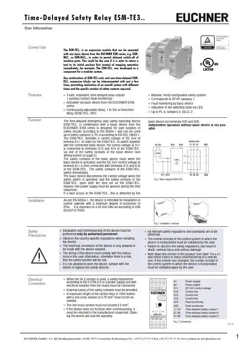
As per EN 60204-1, the device is intended for installation in control cabinets with a minimum degree of protection of IP54. It is mounted on a 35-mm DIN rail according to DIN EN 60715 TH35.• Modular, freely configurable safety system • Corresponds to STOP category 1 • Fault monitoring by basic device • Indication of the switching state via LED • Up to PL d, category 3, SILCL 2Correct UseThe ESM-TE3.. is an expansion module that can beoperatedwith any basic device from the EUCHNER ESM series, e.g. ESM-BA2.. or ESM-BA3.., in order to permit delayed switch-off of machine parts. This could be the case if it is safer to return a tool to its initial position first instead of stopping operation immediately, for example. The ESM-TE3.. was developed as a component for a modular system.Any combination of ESM-TE3 units and non-time-delayed ESM-ES3.. expansion blocks can be interconnected with just a few lines, permitting realization of an overall system with different times and the specific number of safety contacts required.Features • 3 safe, redundant, time-delayed relay outputs 1 auxiliary contact (fault monitoring)• Activation via basic device from the EUCHNER ESM series• Continuously adjustable delay, 1 to 30s or fixed time delay (ESM-TE3..-05S) FunctionThe time-delayed emergency stop safety switching device ESM-TE3.. in combination with a basic device from the EUCHNER ESM series is designed for safe isolation of safety circuits according to EN 60204-1 and can be used up to safety category 3, PL d according to EN ISO 13849-1. The ESM-TE3.. provides a control voltage of DC 24V at terminal S11. In order for the ESM-TE3.. to switch together with the connected basic device, the control voltage at S11 is connected to terminals S15 and S16 of the ESM-TE3.. via one of the safety contacts of the basic device (see Wiring section on page 2).The safety contacts of the basic device close when the basic device is activated, and the DC 24V control voltage at terminal S11 is then connected with terminals S15 and S16 of the ESM-TE3... The safety contacts of the ESM-TE3.. switch immediately.The basic device disconnects the control voltage when the safety switch is operated, and the safety contacts of the ESM-TE3.. open after the time set on the ESM-TE3.. elapses (the power supply must be present during the time sequence).If a fault occurs in the ESM-TE3.., this is detected by the Electrical Connection• When the 24 V version is used, a safety transformeraccording to EN 61558-2-6 or a power supply unit with electrical isolation from the mains must be connected. • External fusing of the safety contacts must be provided. •A maximum length of the control lines of 1000 meters with a line cross section of 0.75 mm 2 must not be ex-ceeded.• The line cross section must not exceed 2.5 mm 2. •If the device does not function after commissioning, it must be returned to the manufacturer unopened. Open-ing the device will void the warranty.InstallationSafetyPrecautionsFig. 1 Block diagram ESM-TE3..Fig. 2 Installation / removalA1: Power supply A2 : Power supplyS11: DC 24V control voltage S10: Control line S15: Control line S16: Control line S25: Fault monitoring S26: Fault monitoring17-18: Time-delayed safety contact 1 27-28: Time-delayed safety contact 2 37-38: Time-delayed safety contact 3basic device via terminals S25 and S26.Independent operation without basic device is not pos-sible .• All relevant safety regulations and standards are to beobserved.• The overall concept of the control system in which the device is incorporated must be validated by the user. • Failure to observe the safety regulations can result in death, serious injury and serious damage.• Note down the version of the product (see label “Vx.x.x”) and check it prior to every commissioning of a new de-vice. If the version has changed, the overall concept of the control system in which the device is incorporated must be validated again by the user.• Installation and commissioning of the device must be performed only by authorized personnel .• Observe the country-specific regulations when installing the device.• The electrical connection of the device is only allowed to be made with the device isolated.•The wiring of the device must comply with the instruc-tions in this user information, otherwise there is a risk that the safety function will be lost.•It is not allowed to open the device, tamper with the device or bypass the safety devices.Hinweis: Während der Inbetriebnahme sind die unter …Elektrischer Anschluss“ aufgeführten Punkte zu berücksichtigen. Commissioning Procedure1. Wiring ESM-TE3..:Wire the ESM-TE3.. with the EUCHNER basic device according to your application (see Fig. 1 to Fig. 2). 2. Wiring basic device:Wire the basic device according to the required Perform-ance Level determined (see user information for the basic device).3. Wiring feedback loop:Wire the feedback loop as shown in Fig. 3 and Fig. 4. 4. Wiring power supply:Connect the power supply to terminals A1 and A2 (Fig. 5). Warning: Wiring only in de-energized state. 5. Setting delay time:Set the desired time delay on the rotary knob and seal the knob with the supplied sticker.(Not for ESM-TE3..-05S because of 0.5 seconds fixed delay time). Warning:Scale division lines should be regarding only as a setting aid. Always make sure to measure the delay time.6. Starting the device:Switch the operating voltage on. Warning:If the “Automatic start” starting behavior is set on the basic device, the safety contacts will close immediately.If the “Monitored manual start” starting behavior is set, close the start button on the basic device to close the safety contacts.The LEDs K1 and K2 on the basic device and on the ESM-TE3.. are lit when the safety contacts are closed. 7. Triggering safety function:Open the emergency stop circuit by actuating the con-nected safety switch. The safety contacts of the basic de-vice open immediately; the safety contacts of the ESM-TE3.. open after expiration of the time set on the rotary knob.Warning: Measure the delay time. 8. Reactivation:Close the emergency stop circuit. If “Automatic start” is selected on the basic device, the safety contacts will close immediately.If the “Monitored manual start” starting behavior is set, close Depending on the application, the device must be wired with a EUCHNER basic device as shown in Fig. 1 to Fig. 2.ApplicationsFig. 3: Feedback LoopContactors connected to the ESM-TE3.. or the basic devices are monitored via the feedback loop of the basic device. K A and K B are the positively driven contacts of the connected contactor or expansion module.Fig. 2: Connection of several ESM-TE3.. units to basic deviceIf further ESM-TE3.. units are to be integrated into the system, terminals S11 must be connected in parallel on all ESM-TE3.. units. This also applies to terminals S10 and terminals S15/S16. The feedback-loops (S25-S26) of the several expansion devices have to be wired in series to the start of the basic device (see Fig.3 respective Fig. 4).Fig. 1: Connection of ESM-TE3.. to basic deviceWiring of the ESM-TE3.. via only 4 lines:A safety contact of the EUCHNER basic device (e.g. 13-14) activates the relays of the ESM-TE3.. (S11 and S15/S16). Two lines on S25 and S26 are required for feedback/faultmonitoring. According to the application, they have to be wired according to Fig. 3 respective Fig. 4.A fault in the ESM-TE3.. thereby prevents the entire safety chain from restarting. Earth faults in the control lines are de-tected in addition to internal faults.WiringFeedback LoopNotice:In order to activate earth fault monitoring, S10 must be con-nected to PE (protective earth) on the AC115/230V devices. With AC/DC 24 V, connect PE only to the power supply unit according to EN60204-1.Fig. 4: Feedback Loop with Auto-StartContactors connected to the ESM-TE3.. or the basic devices are monitored via the feedback loop of the basic device. K A and K B are the positively driven contacts of the connected contactor or expansion module.Power supply andSafety contactsFig. 5:Power supply A1 and A2.(Power supply according to techn. data )Fig. 6:Connecting load to safety contacts.(Figure shows example.Voltage …+V“ according to techn. data)S12S21MaintenanceOnce per month, the device must be checked for proper function and for signs of tampering and bypassing of the safety function (to do this, check the wiring of the device and activate the emergency stop function. Check the delay time). Techn. DataOperating voltage ESM-TE301 ESM-TE302 ESM-TE303AC/DC 24 V AC 115V AC 230V Rated supply frequency 50-60 Hz Permissible deviation + / - 10% Power consumption DC 24V AC 230V approx. 1.5 W approx. 4 VA Delay timeESM-TE3.. 1 to 30 s, continuously adjustable ESM-TE3..-05S 0.5 s fixed Control voltage at S11 DC 24 V Control current S11...S14 max. 40mA Safety contacts 3 NO contactsSignaling contacts 1 NC contact; monitoring contact for basic device Max. switching voltage AC 250 VSafety contact breaking capacity AC: 250 V, 1500 VA, 6 A for ohmic load, 250 V, 4 A for AC-15DC: 24 V, 30 W, 1.25 A for ohmic load; 24 V, 2 A for DC-13Max. total current through all 3 contacts: 10.5 A Minimum contact load 24 V, 20mA Contact fuses 6 A gGLine cross section 0.14 - 2.5 mm 2Max. length of control line 1000 m with 0.75 mm 2 Contact material AgNiContact service life mech. approx. 1 x 10⁷ operating cycles Test voltage2.5 kV (control voltage/contacts) Rated impulse withstand voltage, leakage path/air gap 4 kV (DIN VDE 0110-1) Rated insulation voltage 250 V Degree of protection IP20 Temperature range DC 24V: -15°C to +60°C AC 230V/115V/24V: -15°C to +40°C Degree of contamination 2 (DIN VDE 0110-1) Overvoltage category 3 (DIN VDE 0110-1) Weight approx. 230gMounting DIN rail according to EN 60715 TH35Note:Additional data can be requested from the manufacturer for applications that deviate from these conditions.SafetyCharacteristics According to EN ISO 13849-1The device is certified according to EN ISO 13849-1 up to a Performance Level of PL d.Device cannot be switched on again after an emergency stop:• Check whether the emergency stop circuit was closed again.• Was the start button opened before closing of the emer-gency stop circuit (with manual start)? • Is the feedback loop closed?• Is the power supply present during the time sequence? If the fault still exists, perform the steps listed under “Commissioning Procedure”.If these steps do not remedy the fault either, return the device to the manufacturer for examination.Opening the device is impermissible and will void the warranty.Device does not switch on:• Check the wiring of the ESM-TE3..and the basic device by comparing it with the wiring diagrams (also see user information for the basic device).• Check the safety switch used on the basic device for correct function and adjustment.• Check whether the emergency stop circuit of the basic device is closed.• Check whether the start button on the basic device (with manual start) is closed.• Check the operating voltage at A1 and A2 on the basic device and on the ESM-TE3... • Is the feedback loop closed?What to Do in Case of a Fault?The device is otherwise maintenance free, provided that it was installed properly.Safety characteristics according to EN ISO 13849-1 for all variants of ESM-TE3 Load (DC-13; 24V) <= 0,1A <= 1A <= 2A T10d [years] 20 20 20 Category: 3 3 3 PLd d d PFHd [1/h]: 1,03E-07 1,03E-07 1,03E-07 nop [cycle / year]<= 400.000<= 73.000<= 17.000Subjecttotechnicalmodifications,noresponsibilityisacceptedfortheaccuracyofthisinformation.©EUCHNERGmbH+Co.KG975-1-6/19(TranslationoftheOriginalOperatingInstructions) DimensionDrawingFixedTerminalsPlug-InTerminals。
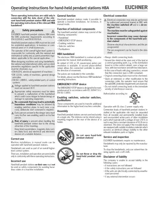
These operating instructions are valid only in connection with the data sheet of the rele-vant hand-held pendant station HBA and with the operating instructions of the relevant HBA handwheel!Correct useMachine installations in manual mode can be operated with hand-held pendant stations.Handwheels are used as part of an overall higher-level control system.Their use, installation and operation are permissible only in conformity with these operating instructions.Incorrect useHand-held pendant stations on their own must not be used as safety components for avoiding hazar-dous states in a machine installation.General functionHand-held pendant stations make it possible to operate a machine installation, for instance, in manual mode.Function of individual componentsThe hand-held pendant station may consist of the following components: HandwheelEMERGENCY-STOP device Enabling switches Selector switches PushbuttonsHBA handwheelThe electronic HBA handwheel is a universal pulse generator for manual shaft positioning.An output of 100 or 25 square-wave pulses per revolution is available. A second phase-shifted output allows the connected controller to detect the direction of movement.The pulses are evaluated in the controller.For details, please see the Electronic HBA handwheel operating instructions.EMERGENCY-STOP deviceThe EMERGENCY-STOP device is designed to be mani-pulation-proof in accordance with IEC 60947-5-1/EN ISO 13850.Enab ling switches, selector switches,pushbuttonsThese components are used to transfer additional information to the higher-level machine controller.AssemblyHand-held pendant stations are not used exclusively at a single site. The stations can be stored using a mounting magnet on the rear of the device or a holder.Electrical connectionAlways shield connecting leads.Ground the shield at the open end of the lead at a central grounding point, e.g. in the distribution board or in the control cabinet, over a large sur-face, with low resistance and with low inductance. In the case of leads with plug connectors, ensure that the connection type is EMC-compliant.Original connecting leads must not be shortened. G iven an extension or other modification to the connection cable, the operator must ensure that the valid EMC protection requirements are observed. Do not install connecting leads in the immediate vicinity of interference sources.Authorization according to:Operation with UL-class 2 power supply only.Connection leads of hand-held pendant stations in-stalled at the application site must be separated from all movable and permanently installed leads and non-insulated active parts of other installation parts which operate with a voltage of over 150 V, in such a way that a constant clearance of 50.8 mm is observed. This does not apply if the movable leads are equipped with suitable insulation materials which possess an identical voltage stability to the other relevant installation parts or higher.Service and inspectionEUCHNER handwheels require no maintenance.Handwheels may only be repaired by the manufac-turer.To clean the handwheels, only use solvent-free cle-aning agents and a soft cloth.Disclaimer of liabilityThe company is unable to accept liability in the following cases:if instructions are not followedif the safety instructions are not followedif the units are electrically connected by unautho-rised personnelif any external intervention occursDo not open hand-held pendant stations!Do not throw or drop the hand-held pendant stati-ons!LISTEDPOW. CONV. EQ.82HAEUCHNER GmbH + Co. KG Kohlhammerstra ße 16D-70771 Leinfelden-Echterdingen Tel. +49/711/75 97-0Fax +49/711/75 33 16www.euchner.de ***************S u b j e c t t o t e c h n i c a l m o d i f i c a t i o n s ; n o r e s p o n s i b i l i t y i s a c c e p t e d f o r t h e a c c u r a c y o f t h i s i n f o r m a t i o n .© E U C H N E R G m b H + C o . K G072850-05-02/12 (T r a n s l a t i o n o f t h e o r i g i n a l o p e r a t i n g i n s t r u c t i o n s )ColourGrey RAL 7040/Black RAL 9004Weight1.3 kg Operating temperature 0 °C ... +50 °C Storage temperature -20 °C ... +50 °CHumidity, max.80 %(condensation not permissible)Degree of protection to the frontIn accordance with EN60529 / IEC529IP 65In accordance with NEMA 250-12Resistance to vibrationVibrations (3 axes)DIN/IEC 68-2-6Shock (3 axes)DIN/IEC 68-2-27EMC protection requirements EN 61000-6-2in accordance with CEEN 61000-6-4Switching elements Max. 2 NC contactsUtilization categoryDC-13according to IEC 60947-5-1U e =24 V / I e= 3 A Resistive loadAC 30 V / 0.4 ADC 30 V / 0.1 A Switching voltage, max.30 V DC Switching current, max.0.1 A Switching capacity, max.1 VA see wiring diagramSwitching voltage, max.25 V Switching capacity, max.0,2 VAwww.euchner.deTechnical data, handwheelSee relevant operating instructions for HBA hand-wheel.AccessoriesSee EUCHNER catalogue for hand-held pendant stations or www.euchner.de.。
德国EUCHNER安士能安全开关使用说明
德国EUCHNER安士能安全开关CTM-LBI-BR-U-ZZ-SA-P-161496 (订货号161496)
CTM-LBI-BR应答机编码安全开关,M12,卫生型
整合了锁止功能及集成评估电子装置的安全开关
串联连接(配有全面诊断功能,可与ESM-CB组合使用)
配有短路电流监控功能
2路安全输出(半导体输出)
双稳态门锁功能
安全等级4/PL e,符合EN ISO 13849-1要求
触发力44 N
拔出力32 N
8针M12接插头
特殊编码
卫生型
德国EUCHNER安士能安全开关特殊编码安全评估
每个触发块都是开关仅识别初始化触发块也可以额外进行触发块初始化。
EUCHNER安全开关仅在识别到最近一次触发块初始化的情况下才可执行此操作。
锁止类型
CTM?LBI 门锁功能通过输入信号来操作。
此类型门锁可
在安全门开启且电力故障或是设备断电时防止人员意外将自己锁闭在内部。
电磁线圈没法得电时的开关解锁。
EKS Profinet on Siemens S7-300 – reading in EKS Electronic-KeysContentsComponents/modules used (2)EUCHNER (2)Others (2)Functional description (2)General (2)Example of an Electronic-Key structure (2)Setting the EKS Electronic-Key adapter (3)Profinet addressing (3)Write-protection setting (3)Configuration in the control system (4)Hardware (4)Programming in the control system (6)Global data blocks (6)STL program for retrieving the Electronic-Key content (7)Important note – please observe carefully! (10)Components/modules usedEUCHNERDescription Order no./item designationEKS Profinet 106305 / EKS-A-IIX-G01-ST02/03EKS Electronic-Key 077859 / EKS-A-K1RDWT32-EU084735 / EKS-A-K1BKWT32-EU091045 / EKS-A-K1BLWT32-EU094839 / EKS-A-K1GNWT32-EU094840 / EKS-A-K1YEWT32-EUTip: More information and downloads about the aforementioned EUCHNER products can be found at www.EUCHNER.de. Simply enter the order number in the search box.OthersDescription ItemS7-300, CPU 315F-2 PN/DP 6ES7315-2FJ14-0AB0Functional descriptionGeneralThe EKS is connected to a Siemens S7-300 PLC via the Profinet. All data corresponding to the data structure below should be read out.Example of an Electronic-Key structureThe data on the Electronic-Key are structured as follows:Byte no. Description Type Length Explanation103 – 104 KEYCRC CRC 2 bytes Checksum over a certain part of the Electronic-Key as copy protection.Refer to the EKM manual for details about the CRC.105 – 112Expiry date Date 8 bytes Electronic-Key expiry date.113 – 114 Authorization level Word 2 bytes Authorization level for access to the machine.115 Department Byte 1 byte Number describing a limited quantity of machines or installations.116 – 123 KeyID KeyID 8 bytes The KeyID is a number that is permanently pre-programmed on theElectronic-Key by EUCHNER. This number is different for each Electron-ic-Key. This number can be used to identify workers.The structure corresponds to application example AP000169-2…Setting the EKS Electronic-Key adapterProfinet addressingThe device is to receive the address via the Siemens configuration software Simatic Manager. Accordingly, all switches are set to OFF on DIP switch S2.Figure 1The device is to receive the DCP name via the Siemens configuration software Simatic Manager. Accordingly, all switches are set to OFF on DIP switch S3.Figure 2Write-protection settingThe device is configured only for reading. Correspondingly, DIP switch S1.1 is set to ON.Figure 3Configuration in the control systemHardwareSimatic Manager version 5.5+SP1 is used for configuration. To perform parameter assignment for the EKS on Profinet drag the object “EKS-A-IIX-G01-ST02/03” to the Profinet. The address range can remain set at 256 to 383.When a new Electronic-Key is inserted, the data are always read automatically from byte 0. As the user data are at the end of the Electronic-Key instead of at the beginning in this example, the actual user data are restricted. Nevertheless, a 128-byte range always must be provided in the input.Figure 4Set the DCP name and the device number in the properties of the EKS Profinet. The default name “EKS-PN” and the device number 1 are used in this example.Figure 5An update time of longer than 128 ms must be set in the object properties on the “IO Cycle” tab in the “Interface” slot of the EKS Profinet.Figure 6The alarm settings will not be addressed in this example.Under the object properties on the “Parameters” tab in the “Read: 128 bytes” slot, it is set that the user data are to be retrieved with a length of 21 bytes from start address 103. The 21 bytes consist of the user data with a length of 13 bytes and the KeyID with a length of 8 bytes. They are therefore retrieved together and stored from data byte 1 in the input range. The status word of the EKS Profinet is located in data byte 0 of the input range.Figure 7Programming in the control systemGlobal data blocksA data block is created for saving the received data for the EKS.The data are created in a structured manner in the data block for reading, with all data items longer than one byte being created as individual bytes to circumvent the even-numbered alignment in the control system. The data block must be the same length as the input range of the EKS, otherwise the system function for reading will not work.DB1, ReadBufferEKSFigure 8DB10, instance module for FB1As the function module FB1 operates with static variables, a DB must be used as an instance module. In the example, DB10 is created for this purpose.STL program for retrieving the Electronic-Key contentThe reading program is programmed in FB1 in this example. The program reads only when an Electronic-Key is inserted and new data are ready. An Electronic-Key that has been read in once will not be read in again. The data from byte 103 (KeyCRC), including the KeyID, are read and are provided in data block DB1 from byte 1 for further processing. 21 bytes of user data in total are re-trieved from the EKS Electronic-Key.The status bye of EKS is saved in byte 0 DB1.Description of the interfaceInput dataNone.Output dataError message, new Electronic-Key and status of the DP slave.Input/output dataNone.Static dataThe KeyRead marker is created statically. This marker identifies whether an Electronic-Key has already been completely read one time. Data are retrieved only if the marker is not set. The marker is reset whenever there is no longer an Electronic-Key in the EKS. Temporary dataNone.Changed registersA1, A2, SWUnchanged registersAR1, AR2, DBR1, DBR2System functions usedSFC14, DPRD_DAT – read standard DP slaves/PROFINET IO devicesGlobal dataData block DB1 with a minimum size of 128 bytes is assumed.The content of data block DB1 is completely overwritten.Symbol tableFigure 10STL program in FB1- ReadEKS//Retrieval of data from the EKS Electronic-Key// Check of whether an Electronic-Key was inserted, and data retrieval only if this is the caseU "EKSIn" // Check whether an Electronic-Key is insertedSPB MKEY // If inserted, check whether data have already been retrieved R #KeyRead // Mark that a new Electronic-Key can now comeSPA MRET// Electronic-Key is inserted// Check whether the Electronic-Key is newMKEY: U #KeyRead // If KeyRead is set, this Electronic-Key has already been read SPBN MRD // Retrieve data only from new Electronic-Key// No new Electronic-Key inserted, no errorMRET: R #Error // Feedback, no errorR #NewKey // Feedback, no Electronic-KeyBEFigure 11a// Reading of data from EKS into DB1MRD: CALL "DPRD_DAT" // Call of SFC 14 DPRD_DATLADDR :=W#16#100 // Address of the EKS memory rangeRET_VAL:=MW1 // FeedbackRECORD :=P#DB1.DBX0.0 BYTE 128 // Start address of the DB for reception, length must be 32// Check whether an error occurredL MW 1L 0 // Only return value 0 is OK==ISPBN MERR // If a value <> 0 was returned in marker word 1: error// Electronic-Key read completely, the data are now in DB1S #KeyRead // Note that reading was complete with this counter valueS #NewKey // Report back that a new Electronic-Key was read completelyR #Error // No errorsBEFigure 11b// Error processingMERR: L MW 1 // DP status as feedback in case of errorT #DPStatusS #Error // Return value = 1, error occurredR #NewKeyBEFigure 11cFB1 call//Retrieval of data from the EKS Electronic-KeyCALL "Read EKS" , "Data FB1"Error :=M0.0 // Return value for errorNewKey :=M0.1 // Return value, whether new Electronic-Key DPStatus:=#Status // Status of the DP slaveU M 0.0 // Check whether error occurredSPB MERR // If values = 1, jump to error routine Figure 12Important note – please observe carefully!This document is intended for a design engineer who possesses the requisite knowledge in safety engineering and knows the ap-plicable standards, e.g. through training for qualification as a safety engineer. Only with the appropriate qualification is it possible to integrate the introduced example into a complete safety chain.The example represents only part of a complete safety chain and does not fulfill any safety function on its own. In order to fulfill a safety function, the energy switch-off function for the hazard location and the software within the safety evaluation must also be considered, for example.The introduced applications are only examples for solving certain safety tasks for protecting safety doors. The examples cannot be comprehensive due to the application-dependent and individual protection goals within a machine/installation.If questions concerning this example remain open, please contact us directly.In accordance with Machinery Directive 2006/42/EC, the design engineer of a machine or installation is obligated to perform a risk assessment and take measures to reduce the risk. When doing this, the engineer must comply with the applicable national and international standards. Standards generally represent the current state of the art. Therefore, the design engineer should continu-ously inform himself about changes in the standards and adapt his considerations to them. Relevant standards include EN ISO 13849 and EN 62061. This application must be regarded only as assistance for the considerations about safety measures.The design engineer of a machine/installation is obligated to assess the safety technology itself. The examples must not be used for assessment, because only a small excerpt of a complete safety function was considered in terms of safety engineering here. In order to be able to use the safety switch applications correctly on safety doors, it is indispensable to observe the standards EN ISO 13849-1, EN ISO 14119 and all relevant C-standards for the respective machine type. Under no circumstances does this doc-ument replace the engineer’s own risk assessment, and it cannot serve as the basis for a fault assessment.Particularly in case of fault exclusion, it must be noted that this can be performed only by the design engineer of a machine or installation and requires a reason. General fault exclusion is not possible. More information about fault exclusion can be found in EN ISO 13849-2.Changes to products or within assemblies from third-party suppliers used in this example can lead to the function no longer being ensured or the safety assessment having to be adapted. In any event, the information in the operating instructions on the part of EUCHNER, as well as on the part of third-party suppliers, must be used as the basis before this application is integrated into an overall safety function. If contradictions should arise between the operating instructions and this document, please contact us directly.Use of brand names and company namesAll brand names and company names stated are the property of the related manufacturer. They are used only for the clear identifi-cation of compatible peripheral devices and operating environments in relation to our products.EUCHNER GmbH + Co. KG · Kohlhammerstraße 16 · 70771 Leinfelden-EchterdingenTelephone:+497117597-0·Fax:+497117597-303·***************·www.euchner.de。
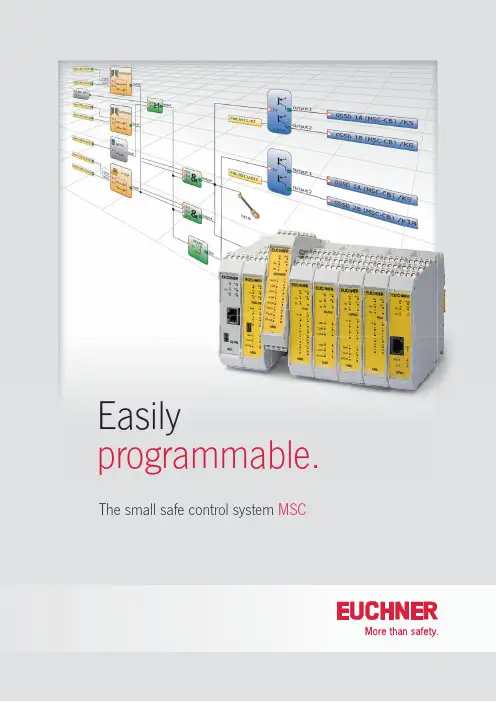
Easilyprogrammable. The small safe control system MSCThe MSC is a universal, freely programmable, modular safety system for the safeguarding of machines and manufacturing equipment. It is suitable for almost all safety-related tasks and can monitor numerous safety-related devices. Programming is easily and conveniently on a PC using the software "EUCHNER Safety Designer". Even with only the base unit MSC-CB it is possible to realize a large number of safety applications with up to 8 inputs and 2 outputs, and that with a housing width of only 22.5 mm.Q Can be expanded easily and specifi callyDepending on the requirements, the MSC off ers a broad range of expansion modules with which the base unit MSC-CB can be expanded almost without limit. The diff erent input and output expansions can be connected to the base unit with the aid of a expansion connector. Various fi eldbus modules can be integrated for straightforward connection to a machine control. The function of the fi eldbus can be specifi cally defi ned in the programming. In this way the control system can be used in a read-only role, or to provide control. All common fi eldbuses are available to suit the related control system.Q Rapid and targeted diagnosticsThe MSC off ers a range of types of diagnostics. The LED indication on the front of all modules provides a straightforward, quick diagnostic feature. In addition it is possible to access directly the program in the base unit with the aid of the software EUCHNER Safety Designer so that the switching state of the inputs and outputs or the logic functions can be checked in detail. Initial setup is signifi cantly simplifi ed in this manner.Q Equipped for an emergencyEach base unit has an internal memory in which the program and all related settings are saved. As an option it is alsopossible to use a separate memory module in the device. A copy of the actual program is automatically saved on this card. It is then possible to replace quickly a faulty device in an emergency, without a PC.Q Protection in compliance with standardsThe small safe control system MSC off ers a high degree of safety. Category 4 and Performance Level e (PL e) in accordance with EN ISO 13849-1 are met by the base unit and all expansion modules.Q Clear softwareThe easy to use and free of charge software "EUCHNER Safety Designer" provides an excellent overview of the logic functions programmed like e-stop, interlock, footswitch. A dedicated module is available for almost every safe device, in this way it is possible to diff erentiate between the emergency stop and an interlock at a glance.The small safe control systemMSCThe expansion modules for the MSCMSC-CE-PN-121315PROF I NET fieldbusMSC-CE-PR-121310PROFINETfieldbusMSC-CE-CO-121312CANopen fieldbusMSC-CE-US-121316USBconnectionMSC-CE-EC-121313EtherCAT fieldbusMSC-CE-EI-121314EtherNET /IP fieldbusMSC-CE-DN-121311DeviceNet fieldbusMSC-CE-MR-122716Modbus RTU fieldbusMSC-CE-MT-122717Modbus TECP/IP fieldbusMSC-CE-EI2-122718EtherNET /IP 2-PORT fieldbusMSC-CE-FI8-121291I nput expansion with8 safe inputsMSC-CE-FI16-121292I nput expansion with16 safe inputsMSC-CE-AZ-FO4-121298O utput expansion with4 safe relay outputsMSC-CE-AZ-FO4O8-121299O utput expansion with4 safe relay outputs8 monitoring outputsMSC-CE-AC-FO2-121294Output expansion with2 safe semiconductor outputsMSC-CE-AC-FO4-121295Output expansion with4 safe semiconductor outputsMSC-CE-CI1-121317D ecentralized 1-channelcommunication moduleMSC-CE-CI2-121318Decentralized2-channelcommunication moduleMSC-CE-SPMO-1213002 Proximity switchMSC-CE-SPM1H-121301MSC-CE-SPM2H-1213042 Proximity switch 1 or 2 HTL encoderM SC-CE-SPM1TB-122721MSC-CE-SPM2TB-122722 2 Proximity switch 1 or 2 TTL encoderM SC-CE-SPM1S-121303MSC-CE-SPM2S-1213062 Proximity switch 1 or 2 sin/cos encoderMSC-CE-AC-FI8FO2-121290I nput and output expansion with 8 safe inputs2 safe semiconductor outputs 2 monitoring outputsMSC-CE-FM4-121293 I nput expansion with4 pressure sensitive mat inputsTransponder-coded safety switches with guard locking Emergency stop devices Electromechanical safetyswitches with safety functionElectromechanical safetyswitches with guard lockingEnabling switchesElectromechanical safetyswitches with guard lockingThe programming interface "EUCHNER Safety Designer"The software "EUCHNER Safety Designer" provides a graphic confi guration interface for programming the small safe control system MSC. This software has a clear layout and is easy and intuitive to operate. A large number of diff erent safety functions (e.g. e-stop, interlock, footswitch) as well as various logic operators (e.g. 1 out of N, AND, OR, INVERTER) are available for the confi guration. With these features even complex applications can be generated easily. The parameter settings are immediately visible on clicking a module. It is not necessary to open any additional windows. This feature provides a quick overview and makes work easier.To setup the system the programming software on a PC is connected directly to the base unit MSC-CB via a USB cable. This saves time during setup and makes troubleshooting easier.The programs prepared are protected by diff erent access levels. In this way inadvertent changes, incorrect operation or changes to the system confi gura-tion are eff ectively prevented. It is of course possible to change the language.121888-05-05/16 S u b j e c t t o t e c h n i c a l m o d i fic a t i o n s ; n o r e s p o n s i b i l i t y i s a c c e p t e d f o r t h e a c c u r a c y o f t h i s i n f o r m a t i o n . © E U C H N E R G m b H + C o . K G · TAEUCHNER GmbH + Co. KG Kohlhammerstraße 1670771 Leinfelden-Echterdingen Germany Tel. +49 711 7597-0Fax +49 711 753316***************Ordering tableItemDescriptionTerminal set*Order no.MSC-CB-AC-FI8FO2-121289Base unit, 8 safe inputs, 2 safe outputs Six contacts 121289MSC-CE-AC-FI8FO2-121290Expansion unit, 8 safe inputs, 2 safe outputs Six contacts 121290MSC-CE-FI8-121291Expansion device, 8 safe inputs Four contacts 121291MSC-CE-FI16-121292Expansion device, 16 safe inputsSix contacts 121292MSC-CE-FM4-121293Expansion device, 4 pressure-sensitive mats Six contacts 121293MSC-CE-AC-FO2-121294Expansion device, 2 safe outputs Four contacts 121294MSC-CE-AC-FO4-121295Expansion device, 4 safe outputs Six contacts 121295MSC-CE-AZ-FO4-121298Expansion device, 4 safe relay outputs Four contacts 121298MSC-CE-AZ-FO4O8-121299Expansion device, 4 safe relay outputs Six contacts 121299MSC-CE-PR-121310Expansion device, PROFIBUS fieldbus Two contacts 121310MSC-CE-DN-121311Expansion device, DeviceNET fieldbus Two contacts 121311MSC-CE-CO-121312Expansion device, CANopen fieldbus Two contacts 121312MSC-CE-EC-121313Expansion device, EtherCAT fieldbus Two contacts 121313MSC-CE-EI-121314Expansion device, EtherNET/IP fieldbus Two contacts 121314MSC-CE-PN-121315Expansion device, PROFINET fieldbus Two contacts 121315MSC-CE-US-121316Expansion device, USB connectionTwo contacts 121316MSC-CE-SPM0-121300Expansion device, 2 Proximity switchFour contacts 121300MSC-CE-SPM1H-121301Expansion device, 2 Proximity switch, 1 HTL encoderFour contacts 121301MSC-CE-SPM1TB-122721 Expansion device, 2 Proximity switch, 1 TTL encoderFour contacts 122721MSC-CE-SPM1S-121303Expansion device, 2 Proximity switch, 1 sin/cos encoderFour contacts 121303MSC-CE-SPM2H-121304Expansion device, 2 Proximity switch, 2 HTL encoderFour contacts 121304MSC-CE-SPM2TB-122722Expansion device, 2 Proximity switch, 2 TTL encoderFour contacts 122722MSC-CE-SPM2S-121306Expansion device, 2 Proximity switch, 2 sin/cos encoderFour contacts 121306MSC-CE-CI1-121317 Decentralized 1-channel communication module Four contacts 121317MSC-CE-CI2-121318 Decentralized 2-channel communication module Four contacts 121318MSC-CE-MR-122716Expansion device, Modbus RTU fieldbus Two contacts 122716MSC-CE-MT-122717Expansion device, Modbus TECP/IP fieldbus Two contacts 122717MSC-CE-EI2-122718Expansion device, EtherNET /IP 2-PORT fieldbus Two contacts 122718AC-PL-B-121308**Expansion connector -121308MSC-M-A1-121309Memory module card-121309AC-SC-02-V04-121319Terminal set 2 contacts screw terminals -121319AC-SC-04-V04-121320Terminal set 4 contacts screw terminals -121320AC-SC-06-V04-121321Terminal set 6 contacts screw terminals -121321C-USB-2.0-A-01,8-MINB-121322USB cable-121322*) Please order separatel **) To expand the base unit MSC-CB an expansion connector must be ordered. One expansion connector is included with all expansion modules.The software "EUCHNER Safety Designer" is included on CD with each base unit MSC-CB (121289).The advantages of MSC at a glance■ Easy to program and multifunctional in use ■ Compact housing for all modules saves space in the control cabinet ■ V arious diagnostics features – can be read easily on the front, in detail in the software ■ Maximum safety (PL e, category 4)■ C onnection of a large number of safety-related devices ■ L ow wiring effort■ C lear programming interface ■ C an be expanded easily and quickly。
Trip RailsTrip DogsEUCHNER GmbH + Co. Phone +49/711/75 97-0P.O. Box 10 01 52 Fax +49/711/75 33 16D- 70745 Leinfelden-Echterdingen www.euchner.deGermany ***************Since its foundation in 1940, EUCHNER has been designing and developing switchgear for controlling diverse motion sequences in the field of machine construction and terotechnology. An innovative development in 1952 was the world’s first multiple position switch.The EUCHNER product range includes every-thing from electromechanical and electronic equipment through to systems and services. Reliability, precision and quality are tested con-tinually and maintained at a high level by compu-ter-controlled development, test and inspection systems for hardware and software.EUCHNER products are sold by competent partners all over the world. Close and optimum contact with our customers is ensured by a large network of independent trading companies, EUCHNER sales offices and our in-house product specialists.We therefore can solve specific problems on-site at any time. An overview of our Technical Sales Offices in Germany and abroad is given on the last page.Production of electromechanical precision switches Bad ÜberkingenTable of ContentsPagesGeneral 4Trip Rails5 - 8Type series ULA...Slot spacing 12 or 16 mm, aluminium according to DIN 69638 form A 5Type series UL...Slot spacing 12 or 16 mm, aluminium buttable side by side6Type series UF...Slot spacing 8, 12 or 16 mm, cast iron according to DIN 69638 form A 7Type series UFA...Slot spacing 8 mm, aluminium8Trip Dogs for Trip Rails9 - 13Type series U1216...according to DIN 69639 form UA / UB Actuation mechanicalfor trip rails ULA / UL / UF, 12 or 16 mm 9Type series UZ1216...Safety dogActuation mechanicalfor trip rails ULA / UL / UF, 12 or 16 mm 10Type series UE1216...Fine adjustment dog Actuation mechanicalfor trip rails ULA / UL / UF, 12 or 16 mm 10Type series U8...Actuation mechanicalfor trip rails UF8 / UFA8, 8 mm11Type series UEN... / UEG...Fine adjustment dog with micrometer Actuation mechanicalfor trip rails ULA / UL / UF, 12 or 16 mm 12Type series UX...Actuation proximityfor trip rails ULA / UL / UF, 8, 12 or 16 mm13G-type Trip Rails14 - 15Type series GF...according to DIN 69638 form C slot spacing 12 or 16 mm 14Type series GFE... / GFR...according to DIN 69638 form C self-assembly kitslot spacing 12 or 16 mm15Trip Dogs for G-type Trip Rails16 - 18Type series G1216...according to DIN 69639 form UA / UB Actuation mechanicalfor G-type trip rail GF..., 12 or 16 mm 16Type series GE... / GENFine adjustment dog with adjustment unit Actuation mechanicalfor G-type trip rail GF..., 12 or 16 mm 17Type series GX... / GEXActuation proximityfor G-type trip rail GF..., 12 or 16 mm18Accessories / Assembly Parts 19Trip Rails / Trip Dogsaccording to DIN 69638 form A Material:aluminiumLength:2010 mm Dimension drawingRefer to page 19 for assembly instructions and accessories.buttable side by side Material:aluminiumLength:1000 / 2000 / 3000 / 4000 mm Dimension drawingaccording to DIN 69638 form A1)Material:cast ironLength:max. 1000 mm Dimension drawing* Only trip rails UF12 and UF16 are in accordance with DIN 69 638.Material:aluminiumLength:2010 mm Dimension drawingRefer to page 19 for assembly instructions and accessories.according to DIN 69639 form UA / UB Material:steel, hardened and polishedFor trip rails:ULA / UL / UF, 12 or 16 mm Dimension drawingSafety trip dog Material:steel, hardened and polishedFor trip rails:ULA / UL / UF, 12 or 16 mm Dimension drawingType series UE1216...Actuation mechanical Fine adjustment dog Material:steel, hardened and polishedFor trip rails:ULA / UL / UF, 12 or 16 mm Dimension drawingMaterial:steel, hardened and polishedFor trip rails:UF8 / UFA8 Dimension drawingFine adjustment dog with micrometer For trip rails:ULA / UL / UF, 12 or 16 mm Dimension drawingNote:The fine adjustment combination UEN1216/UEG1216 may be fitted to all U-trip rails with 12 or 16 mm slot spacing. After clamping adjustment micrometer UEG1216 in position, the fine adjustment dog UEN1216 may be moved as required by turning the micrometer screw.At the desired setting the fine adjustment dog is clamped in position and the adjustment micrometer may be left in position or removed from the trip rail for other uses by unscrewing the locking screw.Type series UX...Actuation proximityMaterial:steel, black finishedFor trip rails:ULA / UL / UF, 8, 12 or 16 mm Dimension drawingG-type trip rail according to DIN 69638 form C Material:steel, galvanizedLength:max. 2000 mm Dimension drawing* Support brackets are required for lengths over 600 mm. Refer to page 19, accessories.Note:Fully-assembled G-type trip rails maybe engraved to your specificationsubject to a surcharge.G-type trip rails according to DIN 69638 form C Material:steel, galvanized Self-assembly kitLength:1000 / 1500 / 2000 mm* Support brackets are required for lengths over 600 mm.Refer to page 19, accessories.Refer to page 22 for assembly instructions.Dimension drawingaccording to DIN 69639 form G Material:steel, hardened and polishedFor G-type trip rails:GF, 12 or 16 mm Dimension drawingFine adjustment dog with adjustment unit Material:steel, hardened and polishedFor G-type trip rails:GF, 12 or 16 mm Dimension drawingType series GX... / GEX...Actuation proximityMaterial:steel, black finishedFor G-type trip rails:GF, 12 or 16 mm Dimension drawingTrip Rails / Trip DogsAccessories / Assembly Parts。
More than safety.Multifunctional Gate BoxQuality, reliability, precision Quality, reliability and precision are the hallmarks of our corporate philosophy.They represent concepts and values to which we feel totally committed. At EUCHNER, quality means that all our employees take personal respon-sibility for the company as a whole and, in particular, for their own field of work. This ind ivid ual commitment to perfection results in prod ucts which are id eally tailored to the customers’need s and the requirements of the market. After all: our customers and their need s are the focus of all our efforts. Through efficient and effective use of resources, the promotion of personal initiative and courage in find-ing unusual solutions to the benefit of our customers, we ensure a high level of customer satisfaction. We familiar-ize ourselves with their needs, require-ments and prod ucts and we learn from the experiences of our cus-tomers’ own customers.EUCHNER – More than safety.Quality –made by EUCHNERMore than safety.Around the world –the Swabian pecialis ts in motion s equence control for mechanical and s ys -tems engineering.EUCHNER’s history began in 1940 with the establishment of an engineering office by Emil Euchner. Since that time, EUCHNER has been involved in the design and development of switch-gear for controlling a wide variety of motion sequences in mechanical and systems engineering. In 1953, Emil Euchner found ed EUCHNER +Co., a milestone in the company’s history. In 1952, he developed the first multiple limit switch –to this day a symbol of the enterprising spirit of this family-owned company.Automation –Safety –ManMachine Tod ay, our prod ucts range from electromechanical an d electronic components to complex system solu-tions. With this wide range of products we can provid e the necessary tech-nologies to offer the right solution for special requirements – regard less of whether these relate to reliable and precise positioning or to components and systems for safety engineering in the automation sector.EUCHNER products are sold through a world -wid e sales network of compe-tent partners. With our closeness to the customer and the guarantee of reliable solutions throughout the globe, we enjoy the confidence of cus-tomers all over the world.Emil Euchner, the company’s founder and inventor of the multiple limit switch, circa 1928.SafetyContents106109-02-05/09General Information 4System Overview 6Components of the Safety System MGB 9 Complete MGB sets in overview 9 Individual MGB modules in overview 10 Installation example 11 Interlocking modules 12 Locking modules 14 Handle module 16 Escape release module 17Technical Data 18 Connection Examples 19 Item Index 20 Product Guide21 Multifunctional Gate Box MGBA handle on the futureThe MGB (Multifunctional Gate Box ) is a unique interlocking or guard locking system for the protection of safety doors on machines and systems.The MGB offers that little bit more : it is more than a safety switch, more than a bolt, and offers a lot more functionality!A system that can grow with your needsEven the basic system comprising handle module and evaluation module (as interlocking module or locking module) includes numerous func-tions.Whether interlocking, guard locking, escape release or other functions such as buttons for start/stop, emergency stop, etc. – The MGB meets all your requirements for safety-related applications.And if your needs grow, the MGB system grows with them. Due to the sophisticated modular design, the evaluation module can quickly become a small operator panel.Be certain of compliance with new standardsPerformance Level e in accordance with EN ISO 13849-1 or SIL3 in ac-cordance with EN 62061 – even with the basic system you can comply with all these requirements. Also the requirements of EN 1088 for protection against tampering are met automatically, as each evaluation module is permanently assigned to a handle module.Safety remains the most important goalAre you locked in inside the danger area? The optional escape release is intuitive to operate! Whether in the event of a power failure or active guard locking – the red door handle is simply pressed down to leave the danger area quickly.For protection when working in the danger area you can block the bolt tongue using up to 3 padlocks in the integrated lockout bar. Unintentionalactivation of the interlocking/guard locking is prevented.Everything at a glanceThe LED display continuously provides you with all important system information. Diagnostics and status check at a glance!Evaluation module(as interlocking module or locking module)Controls and indicators in the housing cover make the MGB an all-rounder. With start button, enable and emergency stop or other functions, the evaluation module becomes a small control terminal.Mechanical releaseFor releasing the guard locking e.g. in case of a power failure.S a v es t i m e a n dm o n ey !Easy to mount and sophisticated designAll MGB modules are optimized for use on fences made of aluminum profiles or steel frames. The MGB is equally suitable for doors hinged on the left or right. Both mounting and changing the actuating direction can be undertaken particularly quickly and easily.The adjustment of safety doors in fences changes over time. With ± 4 mm tolerance in the x direction as well as ± 5 mm in the z direction, the MGB is right there where the problem starts. Nevertheless, if a safety door should be even more out of adjustment, the large funnel in the evaluation module "catches" the bolt tongue and guides it into the center position. Bolt tongue, bolt guide and insertion funnel will also withstand occasional slamming of the door. Robust metal parts protect the MGB against this problem as well. To prevent injuries, the bolt tongue remains retracted with the door open.Y ou always have an overviewFour built-in LEDs continuously provide all the necessary system informa-tion: power supply available, door closed, bolt tongue inserted, guard locking activated, diagnostics messages – everything can be seen clearly at a glance. This information is of course also available to the control system.The advantages of the Multifunctional Gate Box MGB O ptimized for mounting on profiles from 30 - 50 mm T olerance ± 4 mm in x direction, ± 5 mm in z direction Locking force 2000 NThe MGB withstands forces amounting up to 300 Joule O ptional escape release with door handleO ptional buttons and indicators can be integrated directly into the housing S table metal stop prevents damage with bolt tongue extended M arking on the evaluation module as adjustment aid T he actuating direction is easy to change without disassembly H idden mounting holes with slots and metal mounting surfaces H ousing material made of high quality, reinforced plastic E scape release can also be used on doors with double rebate④④④④④④④④④④④④Door handle includedThe MGB has a robust door handle that can be rotated in 90° steps – to suit the installation.Escape release (optional)The safety system MGB can be expanded with an escape release module. The escape release enables people accidentally shut in to open the guard locked door from the danger area.Lockout barThe bolt tongue is blocked for cleaning and service with max. 3 locks.Intelligent bolt tongueThe bolt tongue is reliably detected by transponder as soon as it is inserted in the evaluation module.Escape release moduleHandle moduleF l ex i b l e c o m b i na t i o n s (k i t sy st e m )Very simplemountingRap id es cap eOpe nSafety provided in any situationExplanation of symbolsGeneralComplete MGB sets in overviewDescription of the individual modules starting from page 12.Individual MGB modules in overviewInstallation exampleSolid door stopLED display2 buttons optionalEMERGENCY STOP device optional④④④④Door stopA mechanical door stop is permanently integrated into the evaluation module MGB-L0... There is a marking on the stop that makes adjustment easier.LED displayThe LED display indicates all important system and status information.Buttons (optional)S2 1 NO contact, yellow, illuminatedS 1 NO contact, white, illuminated EMERGENCY STOP device (optional)S1 2 positively driven contacts, EMER-GENCY STOP with turn-to-reset,non-illuminatedMonitoring outputsO1Door positionO2Bolt positionO Not usedO4DiagnosticOrdering guide See page 9 and 10 Technical data See page 18④④④④④④④Interlocking module MGB-L0... Ordering tableOrdering tableGuard locking Solid door stopMechanical release LED display2 buttons optionalEMERGENCY STOP device optional④④④④④④Door stopA mechanical door stop is permanently integrated into the evaluation module MGB-L1.../MGB-L2... There is a marking on the stop that makes adjust-ment easier.Mechanical releaseFor releasing the guard locking, e.g. in case of a power failure.LED displayThe LED display indicates all important system and status information.Buttons (optional)S2 1 NO contact, yellow, illuminated S 1 NO contact, white, illuminated EMERGENCY STOP device (optional)S1 2 positively driven contacts, EMER-GENCY STOP with turn-to-reset,non-illuminated Guard locking typesMGB-L1... The locking arm is held in thelocked position by spring force and is unlocked by solenoid force (closed-circuit current principle).MGB-L2... The locking arm is held in thelocked position by solenoid force and is unlocked by spring force when the solenoid is switched off (open-circuit current principle).Monitoring outputs O1 Door position O2 Bolt positionOPosition of the guard locking O4 Diagnostic output Ordering guide See page 9 and 10Technical data See page 18④④④④④④④Locking module MGB-L1.../MGB-L2...Ordering tableOrdering tableIntelligent bolt tongue Lockout bar Door handle④④④Bolt tongueThe bolt tongue is reliably detected by tran-sponderas soon as it is inserted in the evaluation mod-ule.Lockout barThe bolt tongue can be blocked for cleaning and service with max. 3 locks.Door handleTo suit all installations, the MGB has a robust door handle that can be rotated in 90° steps.The actuating direction can be changed for doors hinged on the left and on the right.Handle module MGB-H-...Handle module MGB-H-...Ordering guide See page 9 and 10Ordering tableEscape release from the danger area Signal red door handle④④Escape releaseThe safety system MGB can be equipped with an escape release module. The escape release enables people shut in to open the guard locked door from the danger area.Escape release module MGB-E...Escape release module MGB-E...Ordering guide See page 9 and 10Ordering tableTechnical data safety system MGB1) Values at a switching current of 50 mA without taking into account the cable lengths.Important : Detailed information on the safety system MGB is available in the system manual for the related evaluation module.The system manual is available at www.euchner.de.Separate operationOperation in a CES-AR switch chainConnection examples24VGND-F1U BX 5.60VX 5.5O 4X 5.4O 3X 5.3O 2X 5.2O 1X 5.1R S TX 4.6MGB-L1-AR...O BX 4.5O AX 4.4N CX 4.3I B X 4.2I AX 4.1U C MX 3.70V MX 3.60V MX 3.5-F2U AX 3.4Sichere SPS Safe PLC-F1DC 24VGND123451CES-AR #1I B12U B23O A34O B4T-Stück/T-Connector097627M12plug-connector(8-pin)5O U T56I A67Buchse/connector (female)Stift/connector (male)0V78R S T812345123451CES-AR #n2I B12U B23O A3T-Stück/T-Connector0976274O B4M12plug-connector(8-pin)5O U T56I A67Buchse/connector (female)Stift/connector (male)0V78R S T812345123451U B20V3O 44O 3T-Stück/T-Connector0976275O 26O 17R S TBuchse/connector (female)Stift/connector (male)MGB-L1-AR... #n8O B12345O AN C12345I BI AStift/connetctor (male)Abschlussstecker/terminating plug097645U C M0V M 0V M -F2U ASichere SPS Safe PLCX 5.6X 5.5X 5.4X 5.3X 5.2X 5.1X 4.6X 4.5X 4.4X 4.3X 4.2X 4.1X 3.7X 3.6X 3.5X 3.4Item IndexIndex by item designationMGB-E-A-100465 100 465 10, 17 MGB-H-AA1A1-R-100464 100 464 10, 16 MGB-L0-AR-AA1A1-M-105331 105 331 10, 12 MGB-L0-AR-AA2A1-M-106106 106 106 10, 13 MGB-L0H-AR-R-105778 105 778 9 MGB-L0H-AR-R-105779 105 779 9 MGB-L0HE-AR-R-105780 105 780 9 MGB-L0HE-AR-R-105781 105 781 9 MGB-L1-AR-AA1A1-M-104302 104 302 10, 14 MGB-L1-AR-AA2A1-M-105328 105 328 10, 15 MGB-L1H-AR-R-105782 105 782 9 MGB-L1H-AR-R-105783 105 783 9 MGB-L1HE-AR-R-105784 105 784 9 MGB-L1HE-AR-R-105785 105 785 9 MGB-L2-AR-AA1A1-M-104303 104 303 10, 14 MGB-L2-AR-AA2A1-M-105797 105 797 10, 15 MGB-L2H-AR-R-105786 105 786 9 MGB-L2H-AR-R-105787 105 787 9 MGB-L2HE-AR-R-105788 105 788 9 MGB-L2HE-AR-R-105789 105 789 9Index by order number100 464 MGB-H-AA1A1-R-100464 10, 16 100 465 MGB-E-A-100465 10, 17 104 302 MGB-L1-AR-AA1A1-M-104302 10, 14 104 303 MGB-L2-AR-AA1A1-M-104303 10, 14 105 328 MGB-L1-AR-AA2A1-M-105328 10, 15 105 331 MGB-L0-AR-AA1A1-M-105331 10, 12 105 778 MGB-L0H-AR-R-105778 9 105 779 MGB-L0H-AR-R-105779 9 105 780 MGB-L0HE-AR-R-105780 9 105 781 MGB-L0HE-AR-R-105781 9 105 782 MGB-L1H-AR-R-105782 9 105 783 MGB-L1H-AR-R-105783 9 105 784 MGB-L1HE-AR-R-105784 9 105 785 MGB-L1HE-AR-R-105785 9 105 786 MGB-L2H-AR-R-105786 9 105 787 MGB-L2H-AR-R-105787 9 105 788 MGB-L2HE-AR-R-105788 9 105 789 MGB-L2HE-AR-R-105789 9 105 797 MGB-L2-AR-AA2A1-M-105797 10, 15 106 106 MGB-L0-AR-AA2A1-M-106106 10, 13Product GuideAutomationPosition SwitchesPosition SwitchesPosition Switches according to EN 50 041Precision Multiple Limit SwitchesInductive Limit SwitchesPlug ConnectorsTrip Rails/Trip DogsInductive Ident SystemsSafetySafety Switches, Metal HousingSafety Switches NZ/TZSafety Switches NX/TXSafety Switches, Plastic HousingSafety Switches NMSafety Switches NP/GP/TPSafety Switches STMSafety Switches STPNon-Contact Safety SwitchesNon-Contact Safety Switches CES/CEM,Transponder CodingNon-Contact Safety Switches CMS,Magnetic CodingSafety Products with integrated Bus InterfaceBolts for Safety GuardsEnabling SwitchesSafety RelaysSafety Relays ESMModular Safety System ESM-FRope Pull SwitchesManMachineElectronic HandwheelsPendant StationsPendant Stations HBAPendant Stations HBE/HBLElectronic-Key-System21KoreaEUCHNER Korea Co., Ltd.RM 810 Daerung Technotown 3rd#448 Gasang-DongKumchon-Gu, SeoulTel.+82-(02)-2107-3500Fax+82-(02)-2107-3999***************.krMexicoSEPIA S.A. de C.V.Maricopa # 10302, Col. Napoles.Del. Benito Juarez03810 Mexico D.F.Tel.+52-55-5536-7787Fax+52-55-5682-2347*****************.mxNew ZealandCSE-W Arthur Fisher Limited15 Polaris PlaceEast Tamaki 2013AucklandTel.+64-9271-3810Fax+64-9265-1362*****************.nzNorwayELIS ELEKTRO ASJerikoveien 161067 OsloTel.+47-22-9056-70Fax+47-22-9056-71*******************PolandEL TRONPl. Wolnosci 7B50-071 WroclawTel.+48-71-3439-755Fax+48-71-3460-225****************PortugalPAM Serviços Tecnicos Industriais Lda.Rua de Timor - Pavilhão 2AZona Industrial da Abelheira4785-123 TROFATel.+351-252-418431Fax+351-252-494739****************.ptRepublic of South AfricaRUBICON ELECTRICAL DISTRIBUTORS4 Reith Street, Sidwell6061 Port ElizabethTel.+27-41-451-4359Fax+27-41-451-1296***************************RomaniaFirst Electric SRL5, Luterana Street010161 BucharestTel.+40-21-31231-39Fax+40-21-31131-93***********************SingaporeSentronics Automation & Marketing Pte Ltd.Blk 3, Ang Mo Kio Industrial Park 2A#05-06Singapore 568050Tel.+65-6744-8018Fax+65-6744-1929**********************.sgSlovakiaEUCHNER electric s.r.o.Spielberk Office CenterHolandská 8639 00 BrnoTel.+420-533-443-150Fax+420-533-443-153***************Int ern ation al r epr e sent ationAustraliaMicromax Pty. Ltd.PO Box 1238Wollongong NSW 2500Tel.+61-2-4271-1300Fax+61-2-4271-8091*********************.auAustriaEUCHNER G.m.b.H.Süddruckgasse 42512 TribuswinkelTel.+43-2252-421-91Fax+43-2252-452-25***************BeneluxEUCHNER (BENELUX) BVVisschersbuurt 233350 AC PapendrechtTel.+31-78-6154-766Fax+31-78-6154-311***************BrazilEUCHNER LtdaAv. Prof. Luiz Ignácio Anhaia Mello,no. 4387S. LucasSão Paulo - SP - BrasilCEP 03295-000Tel.+55-11-2918-2200Fax+55-11-2301-0613*******************.brCanadaIAC & Associates Inc.1925 Provincial RoadWindsor, OntarioN8W 5V7Tel.+1-519-966-3444Fax+1-519-966-6160************************ChinaEUCHNER (Shanghai) Trading Co., Ltd.Unit C, Floor 20Cross Region PlazaNo. 899 Lingling RoadXuhui DistrictShanghai, 200030Tel.+86-21-5774-7090Fax+86-21-5774-7599****************.cnCzech RepublicEUCHNER electric s.r.o.Spielberk Office CenterHolandská 8639 00 BrnoTel.+420-533-443-150Fax+420-533-443-153***************DenmarkDuelco A/SMommarkvej 56400 SønderborgTel.+45-7010-1007Fax+45-7010-1008**************FinlandSähkölehto OyHolkkitie 1400880 HelsinkiTel.+358-9-774-6420Fax+358-9-759-1071********************FranceEUCHNER France S.A.R.L.Parc d'Affaires des BellevuesAllée Rosa LuxembourgBâtiment le Colorado95610 ERAGNY sur OISETel.+33-1-3909-9090Fax+33-1-3909-9099***************Hong KongImperial Engineers & Equipment Co. Ltd.Unit B 12/F Cheung Lee Industrial Building9 Cheung Lee Street Chai WanHong KongTel.+852-2889-0292Fax+852-2889-1814**********************HungaryEUCHNER Ges.mbHMagyarországi Fióktelep2045 TörökbálintTópark utca 1/a.Tel.+36-2342-8374Fax+36-2342-8375***************IndiaEUCHNER (India) Pvt. Ltd.West End Riverview40, First FloorSurvey No. 169/1AundhPune-411 007, IndiaTel. +91-20-6401 6384Fax +91-20-2588 5148********************Teknic Euchner Pvt. Ltd.64, Electronics CityHosur RoadBangalore 560100Tel.+91-80-28520711Fax+91-80-28520900***************************.inIranINFOCELL IRAN CO.# 84, Manoucheri Ave.P.O. Box 81655-861IsfahanTel.+98-311-2211-358Fax+98-311-222-6176********************IsraelIlan At Gavish Automation Service Ltd.26 Shenkar St. Qiryat Arie 49513P.O. Box 10118Petach Tikva 49001Tel.+972-3-922-1824Fax+972-3-924-0761********************ItalyTRITECNICA S.r.l.Viale Lazio 2620135 MilanoTel.+39-02-5419-41Fax+39-02-5501-0474******************JapanSolton Co. Ltd.2-13-7, Shin-YokohamaKohoku-ku, YokohamaJapan 222-0033Tel.+81-45-471-7711Fax+81-45-471-7717***************.jpSloveniaSMM d.o.o.Jaskova 182000 MariborTel.+386-2450-2326Fax+386-2462-5160****************SpainEUCHNER, S.L.Gurutzegi 12 - Local 1Polígono Belartza20018 San SebastianTel.+34-943-316-760Fax+34-943-316-405********************SwedenCensit ABBox 33133123 VärnamoTel.+46-370-6910-10Fax+46-370-1888-8**************SwitzerlandEUCHNER AGGrofstrasse 178887 MelsTel.+41-81-720-4590Fax+41-81-720-4599***************TaiwanDaybreak Int'l (Taiwan) Corp.3F, No. 124, Chung-Cheng RoadShihlin 11145, TaipeiTel.+886-2-8866-1234Fax+886-2-8866-1239*****************.netThailandAero Automation Co., Ltd.600/441 Moo 14 Phaholyothin Rd.Kukot, LamlukkaPatumthanee 12130Tel.+66-2-536-7660-1Fax+66-2-536-7877***********************.thTurkeyentek otomasyonPerpa Ticaret Merkezi B BlokKat: 11 No:1622 - 162334384 Okmeydani / IstanbulTel.+90-212-320-2000Fax+90-212-320-1188************************.trUnited KingdomEUCHNER (UK) Ltd.Unit 2 Petre Drive,SheffieldSouth YorkshireS4 7PZTel.+44-114-256-0123Fax+44-114-242-5333***************.ukUSAEUCHNER USA Inc.6723 Lyons StreetEast Syracuse, NY 10357Tel.+1-315-7010-315Fax+1-315-7010-319********************EUCHNER USA Inc.Detroit Office130 Hampton CircleRochester Hills, MI 48307Tel.+1-248-537-1092Fax+1-248-537-1095********************´´5/9www.euc hner.c omHe a d offic eEUCHNER GmbH + Co. KGKohlhammerstraße 1670771 Leinfelden-EchterdingenGermanyTel.+49-(0)711-7597-0Fax+49-(0)711-753316***************More than safety. More than safety. Morthan safety. More than safety. More thansafety. More than safety. More than safeMore than safety. More than safety. Morthan safety. More than safety. More thansafety. More than safety. More than safeMore than safety. More than safety. Morthan safety. More than safety. More thansafety. More than safety. More than safeMore than safety. More than safety. Morthan safety. More than safety. More thansafety. More than safety. More than safeMore than safety. More than safety. Morthan safety. More than safety. More thansafety. More than safety. More than safeMore than safety. More than safety. Morthan safety. More than safety. More thansafety. More than safety. More than safeMore than safety. More than safety. Morsafety. More than safety. More than safethan safety. More than safety. More thansafety. More than safety. More than safeMore than safety. More than safety. Morthan safety. More than safety. More thansafety. More than safety. More than safeMore than safety. More than safety. Morthan safety. More than safety. More thansafety. More than safety. More than safeMore than safety. More than safety. Morthan safety. More than safety. More thansafety. More than safety. More than safeMore than safety. More than safety. Morthan safety. More than safety. More thansafety. More than safety. More than safeMore than safety. More than safety. Morthan safety. More than safety. More thansafety. More than safety. More than safeMore than safety. More than safety. Morthan safety. More than safety. More thansafety. More than safety. More than safeMore than safety. More than safety. Morthan safety. More than safety. More thansafety. More than safety. More than safeMore than safety. More than safety. MorMore than safety.than safety. Moresafety. More thanMore than safety.than safety. Moresafety. More thanMore than safety.than safety. Moresafety. More thanMore than safety.than safety. Moresafety. More thanMore than safety.than safety. Moresafety. More thanMore than safety.than safety. Moresafety. More thanMore than safety.than safety. Moresafety. More thanMore than safety.than safety. Moresafety. More thanMore than safety.than safety. Moresafety. More thanMore than safety.than safety. Moresafety. More thanMore than safety.than safety. Moresafety. More thanMore than safety.than safety. Moresafety. More thanMore than safety.than safety. Moresafety. More thanMore than safety.than safety. Moresafety. More thanMore than safety.than safety. Moresafety. More thanMore than safety.AutomationSafetyManMachineMore than safety.106109-02-05/09 S u b j e c t t o t e c h n i c a l m o d i fi c a t i o n s w i t h o u t n o t i c e , n o l i a b i l i t y w i l l b e a s s u m e d f o r a n y d e t a i l. © E U C H N E R G m b H + C o . K G · T AEUCHNER GmbH + Co. KG Kohlhammerstraße 1670771 Leinfelden-Echterdingen GermanyTel. +49-(0)711-7597-0Fax +49-(0)711-753316***************。
MGB Help for Setup and Service (up to V1.2.3)Page 2/12 Subject to technical modifications 115387-01-04/12Table of contents1Connection (4)1.1Connection of the buttons in the MGB (4)1.2Control of the guard locking (4)1.3Parallel control of the guard locking (5)1.4Operation on safety relay (5)2Troubleshooting (6)2.1LED DIA 1 flashes 2 times (separate operation) (6)2.2LED DIA 1 flashes 2 times (series operation) (6)2.3LED DIA 1 flashes 3 times (7)2.4LED DIA 1 flashes 4 times (separate or series operation) (7)2.5LED DIA 1 flashes 6 times (AR version) (8)2.6LED DIA 1 flashes 7 times (AP version) (8)2.7Separate operation functions on the safety relay, but not series operation (9)3System status tables (10)3.1MGB-AR (10)3.2MGB-AP (11)115387-01-04/12 Subject to technical modifications Page 3/121 Connection1.1 Connection of the buttons in the MGBThe terminal assignment of the switches (lights, buttons, emergency stop, etc.) in the cover of the MGB is not described in the system manual. These terminals can be found in the associated data sheet of the MGBincluded with every delivery. Please contact EUCHNER if the data sheet has been lost, and you will promptly be sent a data sheet. Alternatively, you can look in the MGB catalog.The switches and the emergency stop are floating. However, the lights and the buttons all refer to a common potential. The terminals are to be found on connections X2 and X3.Example:1.2 Control of the guard lockingThe guard locking is typically controlled by a PLC via one channel. The monitoring of the installed solenoid in combination with the locking arm, which represents the locking device as defined in EN 1088, is suitable for PL e.Two-channel activation, e.g. by a safe PLC, is not possible.+MGBPage 4/12 Subject to technical modifications 115387-01-04/121.3 Parallel control of the guard lockingThe guard locking solenoids are supplied from voltage U A. The inputs U CM serve to control the solenoids; the current draw here is only approx. 3 mA. Several U CM inputs can be controlled in parallel if a common 0 V potential is present at OV M.1.4 Operation on safety relayThe MGB can be connected to most conventional safety relays. Since the outputs, similar to those on a so-called OSSD on light barriers or light curtains, produce clock pulses, a connection as described for non-contact systems must be used.115387-01-04/12 Subject to technical modifications Page 5/122 Troubleshooting2.1 LED DIA 1 flashes 2 times (separate operation)Fault symptom:The MGB displays the fault state “input error (e.g. missing test pulses)”.Possible fault causes:④24 V DC missing at inputs I A and/or I B④ A safety evaluation unit or a safe control system with clocking outputs is connected.Remedy:1. Check the wiring and correct it if necessary or switch the clock pulses off2. Open the safety door3. Switch the voltage offorpress the reset button (if present) that controls the integrated reset input.4. Switch the voltage on againorrelease the reset button5. Wait until LED DIA1 flashes three times or stops flashing entirely (after approx. 8 s)6. Close the safety doorThe MGBs are now ready for operation again2.2 LED DIA 1 flashes 2 times (series operation)Fault symptom:The MGB displays the fault state “Input fault (e.g. missing test pulses, illogical switching state of downstream switch)”.Possible fault causes:④24 V DC missing at inputs I A and/or I B④For series operation, I A is connected to O B or I B to O A④In case of series operation, conventional safety components (switching contacts) are connected to I A and/orI B④ A safety evaluation unit or a safe control system with clocking outputs is connected.④All connections are correct, but there is no common potential for the series-connected devices (severalpower supply units for one chain)Remedy:1. Check the wiring and correct it if necessary or switch the clock pulses off2. Open all safety doors on which the DIA LED is flashing (irrespective of the number of flashing pulses)3. Switch the voltage off at all devicesorpress the reset button (if present) that controls ALL integrated reset inputs in the series connectionPage 6/12 Subject to technical modifications 115387-01-04/124. Switch the voltage on againorrelease the reset button5. Wait until LEDs DIA1 flash three times or stop flashing entirely (after approx. 8 s)6. Close the safety doorsThe MGBs are now ready for operation again2.3 LED DIA 1 flashes 3 timesThe device indicates that it is ready to teach in a new handle module. Observe the specifications for teaching ina handle module in the system manual for this purpose.2.4 LED DIA 1 flashes 4 times (separate or series operation)Fault symptom:The MGB displays the fault state “output fault”.Possible fault causes:④The evaluation unit connected to the MGB and the MGB do not have a common reference potential(common ground)④ A ground loop has been produced by bridges having been installed both on the MGB and in the controlcabinet (refer to the system manual for this purpose).④The internal output circuit is damaged.④24 V present at output O A or O BRemedy:1. Check the wiring and correct it2. Open all safety doors on which the DIA LED is flashing (irrespective of the number of flashing pulses)3. Switch the voltage off at all devicesorpress the reset button (if present) that controls ALL integrated reset inputs in the series connection4. Switch the voltage on againorrelease the reset button5. Wait until LEDs DIA1 flash three times or stop flashing entirely (after approx. 8 s)6. Close the safety doorsThe MGBs are now ready for operation again if no fault occurred in the internal output connection. 115387-01-04/12 Subject to technical modifications Page 7/122.5 LED DIA 1 flashes 6 times (AR version)Fault symptom:The MGB displays the fault state “signal sequence incorrect”.Possible fault causes:④This state occurs if, with an MGB, the door was opened from the inside with the escape release or the guardlocking solenoid was not opened before.④If there is an internal fault (break)Remedy:1. Open all safety doors on which the DIA LED is flashing (irrespective of the number of flashing pulses)2. Switch the voltage off at all devicesorpress the reset button (if present) that controls the integrated reset inputs.3. Switch the voltage on againorrelease the reset button4. Wait until LEDs DIA1 flash three times or stop flashing entirely (after approx. 8 s)5. Close the safety doors.If there is no internal fault (break), the MGBs are now ready for operation again.2.6 LED DIA 1 flashes 7 times (AP version)Fault symptom:The MGB displays the fault state “signal sequence incorrect”.Possible fault causes:④This state occurs if, with an MGB, the door was opened from the inside with the escape release or the guardlocking solenoid was not opened before.Remedy:1. Open all safety doors on which the DIA LED is flashing (irrespective of the number of flashing pulses)2. Switch the voltage off at all devicesorpress the reset button (if present) that controls the integrated reset inputs.3. Switch the voltage on againorrelease the reset button4. Wait until LEDs DIA1 flash three times or stop flashing entirely (after approx. 8 s)5. Close the safety doorsThe MGBs are now ready for operation againPage 8/12 Subject to technical modifications 115387-01-04/122.7 Separate operation functions on the safety relay, but not seriesoperationFault symptom:The connection of a separate MGB operation to a safety relay functions, but the connection in series operation to a safety relay does not function despite correct wiring. The safety relay displays a fault or does not switch on. Possible fault causes:The first MGB is connected to the safety relay with its inputs I A and I B, and the current that the safety relay can supply is insufficient.Remedy:Wiring of the first inputs I A und I B directly to the 24 V DC power supply.115387-01-04/12 Subject to technical modifications Page 9/123 System status tables3.1 MGB-AROperating mode LED indicator StateInput faultReady for teach-inOutput faultDiagnosticsSignal sequence erroneousSetupPositive acknowledgment after completion of teach-in operation Normal operationNormal operation, Door openPage 10/12 Subject to technical modifications 115387-01-04/12MGB Help for Setup and Service3.2 MGB-APOperating mode LED indicator StateInput faultReady for teach-inOutput faultDiagnosticsSignal sequence incorrectSetupPositive acknowledgment after completion of teach-in operation Normal operationNormal operation, door open115387-01-04/12 Subject to technical modifications Page 11/12EUCHNER GmbH + Co. KG Telephone +49 711 7597 – 500 (Support) Kohlhammerstraße 16 Fax +49 711 753316D-70771 Leinfelden-Echterdingen www.euchner.de .***************。
Connecting MGB-L1B-PN… to Siemens S7 315F (TIA Portal V13)ContentsGuard locking acc. to EN ISO 14119 actuated by spring force applied – power-ON released (closed-circuit current principle) (2)Components/modules used (2)EUCHNER (2)Others (2)Software (2)Functional description (3)General (3)Data structure (3)Notice (3)Mounting (4)Installing the GSDML file (4)Hardware configuration (9)Creating the safety program (14)Example of depassivation (14)Explanation: (16)Sources (17)Important note – please observe carefully! (18)Guard locking acc. to EN ISO 14119 actuated by spring force applied – power-ON released (closed-circuit current principle)Safety function Guard locking acc. to EN ISO 14119Reliability figures according to EN ISO 13849 Category 4, PL eComponents/modules usedEUCHNERDescription Order no./item designationSet Order no./item designation Evaluation unitSafety system MGB with PROFINET inter-face, guard locking with guard lock moni-toring 117102 / MGB-L1HB-PNC-R-117102117103 / MGB-L1HB-PNC-L-117103117098 / MGB-L1B-PNC-R-117098117099 / MGB-L1B-PNC-L-117099Tip: More information and downloads about the aforementioned EUCHNER products can be found at www. . Simply enter the order number in the search box.OthersDescription ItemSIMATIC S7 CPU315F-2 PN/DP 6ES7315-2FH13-0AB0SIMATIC SM326 DO 8x24V/2A PM 6ES7326-2BF40-0AB08-port switch -Desktop PC -SoftwareFigure 1Functional descriptionGeneralThe MGB-L1B-PN… is guard locking in accordance with EN ISO 14119 according to the closed-circuit current principle. In this example, all safety functions are processed via the PROFIsafe protocol. The MGB is connected to a Siemens 315F-2 PN/DP CPU.Figure 2Data structureInput range, slot 1 - 4: StandardInput range, slot 5: SafeOutput range, slot 1 - 4: StandardOutput range, slot 5: SafeInformation about the output range: Refer to the operating instructions for information about activation of guard locking.NoticeThis application is based on the MGB-PN operating instructions. Please refer to the operating instructions for the technical details. Pay attention to activation of guard locking when using an MGB-L2..-PN (guard locking according to EN ISO 14119 in accordance with the open-circuit current principle).Tip: The operating instructions are available at . Simply enter the order number for the device in the search box.MountingPlease ensure the device is mounted correctly as described in the operating instructions. Also ensure that the handle module is NOT in the operating distance during configuration.Installing the GSDML fileThe latest MGB PROFINET GSDML file and the associated BMP image file (to depict the MGB in the configuration software) are available in the Service/Downloads/Software/GSD-data/MGB area at .Please proceed as follows to install the GSD file in TIA Portal V13:Figure 3Click “Options” and select “Manage general station description files (GSD).”Figure 4Select the folder where you saved the GSMDL file and click “OK.”Figure 5Select the GSDML file suitable for the MGB from the list and click “Install.”Figure 6Enter the corresponding order no. of the bus and guard locking module in the search box for the hardware catalog. The appropri-ate device will be displayed there. Check the information area to determine the GSDML file version. If an older GSDML file has already been installed, you can select the required GSDML file. Drag the selected MGB into your PROFINET network.Figure 7Now assign the appropriate IO controller to the MGB by clicking “Not assigned” and then selecting the IO controller.Hardware configurationOpen the MGB device view. Double-clicking the displayed MGB will show the general settings of the MGB in the bottom window. You can make the corresponding settings there, e.g. assigning the IP address and the diagnostic addresses. The device name and the input and output addresses can be changed in the device overview.Figure 8Click the “assign device name” icon marked in red here.Figure 9Select the suitable device name and the corresponding available devices, and then click “Assign name.” The device name in this application is“euchnermgb” (factory setting from GSD file). Please note that the device name in the device overview must match the assigned device name.Figure 10The PROFIsafe assembly is located in slot 5. Go to the general properties there. They are displayed in the bottom window.Figure 11Enter the same PROFIsafe address you set on the DIP switch (Figure 12) on the MGB-PN in the “F_Dest_Add” field. Refer to the operating instructions for information about setting the PROFIsafe address on the MGB.Figure 12Figure 13Go to “Safety Administration” and open the “Protection” item. Set up a password there. If theF-CPU must be protected by a password as well, please note the “F-CPU access protection” item.Creating the safety programThe F sequence group, the FB and the associated DB are generated automatically in TIA Portal V13. As soon as the program is compiled, a safety program consistency check is performed.Example of depassivationFigure 14Below is an example of how depassivation of the MGB-PN can be performed. The MGB-PN is to be depassivated intentionally using a button on MGB-PN. Refer to the table for the corresponding input address assigned to the button (e.g. S90 = I 0.0). Please con-sider the input and output ranges you assigned to the MGB-PN in the HW configuration.Figure 15The designation of the modules named here can vary, because they are generated automatically. Create the link shown in Figure 15 in FB1. The “ACKNOWLEDGEMENT REQUEST” bit from DB513 (Figure 16) set when the MGB-PN is passivated. User acknowl-edgment using an MGB-PN button must be performed in this example. If the “ACKNOWLEDGEMENT REQUEST“ bit and bit I0.0 are set, the “ACKNOWLEDGEMENT FOR REINTEGRATION” bit is set and the MGB-PN is re-integrated.Click “Compile.” This automatically performs a safety program consistency check. Then load the safety program into your PLC by clicking “Load into Device.” The MGB-PN can now be depassivated at any time by pressing the button. Teach the handle module as described in the operating instructions.Figure 16 (DB513)There must be at least one MGB call in the safe program section to prevent the device from being passivated. Bit I6.1 (ÜK) from the PROFIsafe area of the MGB is then used. Bit ÜK is set when the following conditions are met: door closed/bolt tongue inserted into the locking module/guard locking active.Figure 17One output of the Siemens output card is connected with bit I6.1 (ÜK) in this example.Explanation:ACK_REI (IN 0.2) (BOOL) User acknowledgment on manualreintegration“ACK_REI = 0->1” (positive edge):Reintegration takes place after a positiveedge.Comment:User acknowledgment is possible onlyafter the fault causing passivation hasbeen remedied.User acknowledgment is always requiredfor an “F communication error,” inde-pendentlyof ACK_NEC.ACK_REQ (OUT 2.2) (BOOL) The user can only read this variablein the P periphery data module.“ACK_REQ = 1”:The fault leading to passivation has beenremedied.User acknowledgment for manual reinte-gration (ACK_REI) is now possible.Cause for passivation:“F communication error,” “assembly er-ror,” “channel error”Comment:Once the fault leading to passivation hasbeen remedied and the F system hasrecognized this, the F system sets“ACK_REQ = 1.”After user acknowledgment, the F operat-ing system sets “ACK_REQ = 0.”SourcesElaboration of S7 Distributed Safety project presentation at Technikerschule HannoverSIMATIC Safety Integrated “Passivation and Reintegration of F-I/O considering as example the ET 200S.”Important note – please observe carefully!This document is intended for a design engineer who possesses the requisite knowledge in safety engineering and knows the ap-plicable standards, e.g. through training for qualification as a safety engineer. Only with the appropriate qualification is it possible to integrate the introduced example into a complete safety chain.The example represents only part of a complete safety chain and does not fulfill any safety function on its own. In order to fulfill a safety function, the energy switch-off function for the hazard location and the software within the safety evaluation must also be considered, for example.The introduced applications are only examples for solving certain safety tasks for protecting safety doors. The examples cannot be comprehensive due to the application-dependent and individual protection goals within a machine/installation.If questions concerning this example remain open, please contact us directly.In accordance with Machinery Directive 2006/42/EC, the design engineer of a machine or installation is obligated to perform a risk assessment and take measures to reduce the risk. When doing this, the engineer must comply with the applicable national and international standards. Standards generally represent the current state of the art. Therefore, the design engineer should continu-ously inform himself about changes in the standards and adapt his considerations to them. Relevant standards include EN ISO 13849 and EN 62061. This application must be regarded only as assistance for the considerations about safety measures.The design engineer of a machine/installation has the obligation to assess the safety technology him/herself. The examples must not be used for assessment, because only a small excerpt of a complete safety function was considered in terms of safety engi-neering here.In order to be able to use the safety switch applications correctly on safety doors, it is indispensable to observe the standards EN ISO 13849-1, EN ISO 14119 and all relevant C-standards for the respective machine type. Under no circumstances does this doc-ument replace the engineer’s own risk assessment, and it cannot serve as the basis for a fault assessment.Particularly in case of fault exclusion, it must be noted that this can be performed only by the design engineer of a machine or installation and requires a reason. General fault exclusion is not possible. More information about fault exclusion can be found in EN ISO 13849-2.Changes to products or within assemblies from third-party suppliers used in this example can lead to the function no longer being ensured or the safety assessment having to be adapted. In any event, the information in the operating instructions on the part of EUCHNER, as well as on the part of third-party suppliers, must be used as the basis before this application is integrated into an overall safety function. If contradictions should arise between the operating instructions and this document, please contact us directly.Use of brand names and company namesAll brand names and company names stated are the property of the related manufacturer. They are used only for the clear identifi-cation of compatible peripheral devices and operating environments in relation to our products.EUCHNER GmbH + Co. KG · Kohlhammerstraße 16 · 70771 Leinfelden-EchterdingenTelephone:+497117597-0·Fax:+497117597-303·***************·。
The safe choice – Selection of operation mode with EKS up to PL eService modeOverview of selection of operation modeSelection of operation mode up to PL d with controlsOperating panels have proven their worth over many years of practical use on machines and installations. If an additional operation mode, such as Service mode, is to be added to such machines, it is usually expedient to realize selection of operation mode with controls.Technical implementation is particularly easy in this case. The EKS with data interface or the EKS Light is used as the access system in order to restrict access to certain categories of people as required in the Machinery Directive. The controls are released with the authorization stored on the EKS Electronic-Key. For example, these controls flash depending on the content of the Electronic-Key. This can be realized with the standard PLC, because access to selection of operation mode does not have to fulfill any PL.Controls are used to achieve a PL for selection and activation of an operation mode. Practical examples of how operating mode selection can be implemented with EKS Light can be found in the download area at https://www.euchner.de/en-us/Service/ Downloads/Applications/EKS. Signals are read in the safe control system, and the selected operation mode is signaled byThe procedure was approved by the Institute for Occupational Safety and HealthIFAUrkundeThe EKS SystemThe Electronic-Key-System EKS consists of a read station and at least oneElectronic-Key. The Electronic-Key contains a writable memory. Two differentEKS systems are available: the EKS with data interface and the EKSEKS with data interfaceThe EKS with data interface features an Electronic-Key with freely pro-Compact (left) and mod-ular (right) EKS systemsare availableTIP! More safety through trainingTrain your customers about how to perform dangerous work on the machine. Thereby give them the opportunity to oper-ate the machine safely. If required, the training date or only general verification of training can be noted on the Electron-ic-Key using the EKS with data interface. With this training, you and your customers can be confident of doing everything right and meeting all legal requirements. Simply holding the Electronic-Key constitutes verification of training. Evaluation of the Performance Level (PL) of selection of operation modeThe access system does not have to be implemented according to EN ISO 13849-1. It is not possible to determine a PL for the monitoring of an authorization. by contrast, the selection system and the safe control system of a machine must fulfill the required PL. This is very simple for mechanical controls or key-operated rotary switches.SecuritySecuritySafety = PL e according to EN ISO 13849-1 FSA and EKS Light FSAoutputSelection of safe operation mode with controls and EKS LightPL dAccess systemSelection systemActivation systemActivation in the machineImplementation requires: EKS LightSafe control systemStandard PLC or NC control system Illuminated controlsEUCHNEr application AP000225Selection of safe operation mode with controls and EKS with data interfaceAccess systemActivation systemSelection systemImplementation requires:EKS with PrOFIbUS, PrOFINET, USb or Ethernet TCP/IP Safe control systemStandard PLC or NC control system Illuminated controlsEUCHNEr application AP000234PL dPLCPLCEKS LightEKS busA b C D STrFailsafe PLCFailsafe PLCbusActivation in the machineSelection of safe operation mode with touchscreen and EKS Access systemFurther informationFor detailed information about the various EKS systems and theaccessories, please refer to the product catalogs or visit ourhomepage at .Product informationDetailed product information about our EKS systems and the EKM and EKM Light software for convenient Electronic-Key administration can be found athttp://www.euchner.de/en-us/Products/Electronic-Key-System-EKSApplicationsThe complete AP000169, AP000200 and AP000225 applications, as well as the respective certificates from the Institute for Occupational Safety and Health of the German Social Accident Insurance (Institut für Arbeits- schutz, IFA), can be found in the download area athttp://www.euchner.de/en-us/Service/Downloads/Applications/EKSCatalogs and flyersEKS catalogs and flyers can be found athttp://www.euchner.de/en-us/Service/Downloads12127593-07-07/18 S u b j e c t t o t e c h n i c a l m o d i fi c a t i o n s ; n o r e s p o n s i b i l i t y i s a c c e p t e d f o r t h e a c c u r a c y o f t h i s i n f o r m a t i o n . © E U C H N E r G m b H + C o . K G · TAEUCHNER GmbH + Co. KG Kohlhammerstraße 1670771 Leinfelden-Echterdingen Germany Tel. +49 711 7597-0Fax +49 711 753316***************Your advantages when using EKSfor selection of operation modeC onsistent machine operating concept, including selection of operation modeF ulfills all specifications of the Machinery DirectiveS afe working according to the Occupational Health and Safety requirements can be realized ... with controlsC an be incorporated into existing control panelsF ulfills Pl d according to EN ISO 13849-1I FA-tested procedure ... with touch panelN o additional controls next to the touchscreen requiredF ulfills PL e according to EN ISO 13849-1I FA-tested procedureYour advantages when using EKS systems... with data interfaceA dditional access controls can be programmed, e.g. access to control systems or operating parametersS imple integration into existing bus structuresT raining measures can be stored on the Electronic-KeyA validity expiration date can be stored L ost Electronic-Keys can be blocked V arious interfaces are available:nPrOFINET n PrOFIbUS n USbn Ethernet TCP/IP... EKS LightN o bus system requiredS imple wiring to the control systemE lectronic-Key evaluation takes place in the EKS Light。
Correct useThe ESM-BA3.. is a universal safety emergency stop switching device with three safe relay outputs that can quickly and safely stop the moving parts of a machine or system in case of danger. Applications for the ESM-BA3.. include single- or dual-channel emergency stop circuits and guard monitoring on machines and installations. Before the device is used, a risk assessment must be performed on the machine, e.g. in accordance with the following standards:f EN ISO 13849-1f EN ISO 12100f IEC 62061.Correct use includes observing the relevant require-ments for installation and operation, particularly based on the following standards:f EN ISO 13849-1f EN 60204-1f IEC 62061.Important!f The user is responsible for the integration of the device in a safe overall system. For this purpose, the overall system must be validated, e.g. in accordance with EN ISO 13849-2.f The device user must assess and document remaining risks.f If a data sheet is included with the product, the information on the data sheet applies.Featuresf3 safe, redundant relay outputs1 auxiliary contact (monitoring contact)f Connection of:- Emergency stop buttons- Safety switches- Non-contact safety switches- Safety components with OSSD outputsf Single- and dual-channel operation possiblef Feedback loop for monitoring downstream contac-tors or expansion modulesf Cyclical monitoring of the output contactsf Indication of the switching state via LEDf2 start behaviors possible:- Monitored manual start- Automatic startf Short circuit and ground fault monitoringf Use up to PL e, SILCL 3, category 4FunctionThe safety emergency stop switching deviceESM-BA3.. is designed for safe isolation of safetycircuits according to EN 60204-1 and can beused up to safety category 4, PL e according toEN ISO 13849-1.The internal logic system closes the safety contactswhen the start button is pressed.When the safety switch is opened, the positivelydriven safety contacts are opened and safely switchthe machine off. It is ensured that a single fault doesnot lead to a loss of the safety function and thatevery fault is detected by cyclical self-monitoringno later than when the system is switched off andswitched on again.Fig. 1: Block diagram for ESM-BA3..MountingAs per EN 60204-1, the device is intended for in-stallation in control cabinets with a minimum degreeof protection of IP54. It is mounted on a 35 mmmounting rail according to DIN EN 60715 TH35.Fig. 2: Mounting/removingElectrical connectionf When the 24 V version is used, a safety transform-er according to EN 61558-2-6 or a power supplyunit with electrical isolation from the mains mustbe connected.f External fusing of the safety contacts must beprovided.f A maximum length of the control lines of 1,000 me-ters with a conductor cross-section of 0.75 mm²must not be exceeded.f The conductor cross-section must not exceed2,5 mm².fIf the device does not function after setup, it mustbe returned to the manufacturer unopened. Open-ing the device will void the warranty.A1Power supplyA2Power supplyS11DC 24 V control voltageS10Control lineS21Start control lineS13Control lineS14Control lineS12Control line13-14Safety contact 123-24Safety contact 233-34Safety contact 341-42Monitoring contactFig. 3: ConnectionsSetup procedureNoticeThe items listed under Electrical connection mustbe observed during setup.1. Wiring emergency stop circuit:Wire the emergency stop circuit according to therequired Performance Level determined (see Fig.5 to Fig. 9).2. Wiring start circuit:Wire the start circuit according to Fig. 10 or Fig. 11to set the starting behavior.Attention: If Automatic start is set, bear in mind thatthe safety contacts will switch immediately after thepower supply is connected. If Monitored manual startis set, the start button must be opened after wiring.3. Wiring feedback loop:If your application provides for external contactorsor expansion modules, connect them to the deviceaccording to Fig. 12 or Fig. 13.4. Wiring power supply:Connect the power supply to terminals A1 and A2(see Fig. 14).Attention: Wiring only in de-energized state.5. Starting the device:Switch the operating voltage on.Attention: if the Automatic start behavior is set, thesafety contacts will close immediately.If the Monitored manual start behavior is set, closethe start button to close the safety contacts.LEDs K1 and K2 illuminate.6. Activating safety function:Open the emergency stop circuit by actuating theconnected safety switch. The safety contacts openimmediately.7. Reactivation:Close the emergency stop circuit. If Automaticstart is selected, the safety contacts will closeimmediately.If the Monitored manual start behavior is set, closethe start button to close the safety contacts.What to do in case of a fault?Device does not switch on:f Check the wiring by comparing it to the wiring diagrams.f Check the safety switch used for correct function and adjustment.f Check whether the emergency stop circuit is closed.f Check whether the start button (with manual start) is closed.f Check the operating voltage at A1 and A2.f Is the feedback loop closed?Device cannot be switched on again after an emergency stop:f Check whether the emergency stop circuit was closed again.f Was the start button opened before closing of the emergency stop circuit (with manual start)?f Is the feedback loop closed?If the fault persists, perform the steps listed under Setup procedure.If these steps do not remedy the fault either, return the device to the manufacturer for examination. Opening the device is impermissible and will void the warranty.MaintenanceThe device must be checked once per month for proper function and for signs of tampering and bypassing of the safety function. The device is otherwise maintenance-free, provided that it was installed properly.DisposalPay attention to the applicable national regulations and laws during disposal.EU declaration of conformityThe declaration of conformity is part of the operating instructions, and it is included as a separate sheet with the device.The EU declaration of conformity can also be found at: ServiceIf servicing is required, please contact: EUCHNER GmbH + Co. KG Kohlhammerstraße 1670771 Leinfelden-EchterdingenGermanyService telephone:+49 711 7597-500E-mail:******************Internet:Technical data1) I f several ESM-BA3.. are closely spaced under load, the max. cumulative current is 9 A at an ambient temperature of T = 20 °C, 3 A at T = 30 °C and 1 A at T = 40 °C. If these currents are exceeded, a spacing of 5 mm between the devices must be observed. 2) Additional data can be requested from the manufacturer for applications that deviate from these conditions.Fixed terminals Plug-in terminalsFig. 4: Dimension drawing for ESM-BA3..S u b j e c t t o t e c h n i c a l m o d i fi c a t i o n s ; n o r e s p o n s i b i l i t y i s a c c e p t e d f o r t h e a c c u r a c y o f t h i s i n f o r m a t i o n . © E U C H N E R G m b H + C o . K G 2090073-09-07/22 V 1.1.0 (t r a n s l a t i o n o f t h e o r i g i n a l o p e r a t i n g i n s t r u c t i o n s )ApplicationsDepending on the application or the result of the risk assessment according to DIN EN ISO 13849 1, the device must be wired as shown in Fig. 5 to Fig. 15.Emergency stop circuitFig. 5: D ual-channel emergency stop circuit with short circuit and ground fault monitoring (category 4, up to PL e).Fig. 6: D ual-channel emergency stop circuit with ground fault monitoring (category 3, up to PL d).Fig. 7: S ingle-channel emergency stop circuit withground fault monitoring (category 1, up toPL c).Notice:In order to activate ground fault monitoring, S10 must be connected to PE (protective earth) on the AC115/230V devices. With AC/DC 24 V, connect PE only to the power supply unit according to EN 60204-1.Wire the start circuit in accordance with the applica-tion according to Fig. 10 or Fig. 11.Fig. 8: D ual-channel sliding guard monitoring with short circuit and ground fault monitoring (category 4, up to PL e).Fig. 9: D ual-channel emergency stop circuit withpnp semiconductor outputs / OSSD outputs with short circuit detection (category 4,up to PL e).Starting behaviorFig. 10: M onitored manual start. It is monitored that the start button was opened before the emergency stop buttons close (pre-requisite: operating voltage must not be interrupted).Fig. 11: Automatic start. Max perm. delay duringclosing of the safety switches on S 12 and S13:S12 before S13: 300 ms S13 before S12: anyFeedback loopFig. 12: F eedback loop. Monitoring of externally connected contactors or expansion mod-ules.Fig. 13: F eedback loop with automatic start. Mon-itoring of externally connected contactors or expansion modules.Power supply and safety contactsFig. 14: C onnection of the power supply to terminals A1 and A2 (power supply according to the technical data).Fig. 15: C onnection to switching loads on safety contacts (example contact configura-tion. Differing according to device type.Switching voltages +V corresponding to technical data).。