SEC单极霍尔效应传感器IC SS1438使用手册
- 格式:pdf
- 大小:229.05 KB
- 文档页数:8
*3-2840.090-1*3-2840.090-1 Rev. 3 08/19Signet 2839-2842 电导率电极中文操作手册2839: 0.01 cm-12840: 0.1 cm-12841: 1.0 cm -12842: 10.0 cm -1• English •中文2Signet PVDF电导率传感器3Signet PVDF电导率传感器Signet PVDF电导率传感器45 Signet PVDF电导率传感器6Signet PVDF电导率传感器7Signet PVDF电导率传感器乔治费歇尔·中国上海 021 3899 3899 北京 010 5682 1599 深圳 0755 8228 0172/73 成都 028 8608 8556 西安 029 8819 3-2840.090-1 Rev. 3 08/19 中文© Georg Fischer Signet LLC 2019制造商部件号订货代码描述3-2839-1V 159 001 810电池常数0.01,4.6米电缆,PVDF NPT螺纹配件3-2839-1VD 159 001 811电池常数0.01,4.6米电缆,PVDF ISO螺纹配件3-2840-1V 159 001 812电池常数0.1,4.6米电缆,PVDF NPT螺纹配件3-2840-1VD 159 001 813电池常数0.1,4.6米电缆,PVDF ISO螺纹配件3-2841-1V 159 001 814电池常数1.0,4.6米电缆,PVDF NPT螺纹配件3-2841-1VD 159 001 815电池常数1.0,4.6米电缆,PVDF ISO螺纹配件3-2842-1V 159 001 816电池常数10,4.6米电缆,PVDF NPT螺纹配件3-2842-1VD159 001 817电池常数10,4.6米电缆,PVDF ISO螺纹配件2850电导率/电阻率传感器电子组件3-2850-51159 001 398传感器电子组件,3/4英寸NPT接线盒,单输入/单数字(S³L)输出3-2850-52159 001 399传感器电子组件,3/4英寸NPT接线盒,单输入/单4-20mA输出3-2850-61159 001 400传感器电子组件,通用接线盒,单输入/单数字(S³L)输出3-2850-62159 001 401传感器电子组件,通用接线盒,单输入/单4-20mA输出3-2850-63159 001 402传感器电子组件,通用接线盒,双输入/双数字(S³L)输出3-2850-51-39V 159 001 8182850一体式系统,数字(S³L)输出,电池常数0.01,PVDF NPT螺纹3-2850-51-40V 159 001 8192850一体式系统,数字(S³L)输出,电池常数0.1,PVDF NPT螺纹3-2850-51-41V 159 001 8202850一体式系统,数字(S³L)输出,电池常数1.0,PVDF NPT螺纹3-2850-51-42V 159 001 8212850一体式系统,数字(S³L)输出,电池常数10,PVDF NPT螺纹3-2850-51-39VD 159 001 8222850一体式系统,数字(S³L)输出,电池常数0.01,PVDF ISO螺纹3-2850-51-40VD 159 001 8232850一体式系统,数字(S³L)输出,电池常数0.1,PVDF ISO螺纹3-2850-51-41VD 159 001 8242850一体式系统,数字(S³L)输出,电池常数1.0,PVDF ISO螺纹3-2850-51-42VD 159 001 8252850一体式系统,数字(S³L)输出,电池常数10,PVDF ISO螺纹3-2850-52-39V 159 001 8262850一体式系统,4-20mA输出,电池常数0.01,PVDF NPT螺纹3-2850-52-40V 159 001 8272850一体式系统,4-20mA输出,电池常数0.1,PVDF NPT螺纹3-2850-52-41V 159 001 8282850一体式系统,4-20mA输出,电池常数1.0,PVDF NPT螺纹3-2850-52-42V 159 001 8292850一体式系统,4-20mA输出,电池常数10,PVDF NPT螺纹3-2850-52-39VD 159 001 8302850一体式系统,4-20mA输出,电池常数0.01,PVDF ISO螺纹3-2850-52-40VD 159 001 8312850一体式系统,4-20mA输出,电池常数0.1,PVDF ISO螺纹3-2850-52-41VD 159 001 8322850一体式系统,4-20mA输出,电池常数1.0,PVDF ISO螺纹3-2850-52-42VD159 001 8332850一体式系统,4-20mA输出,电池常数10,PVDF ISO螺纹替换部件3-8050-1159 000 753通用接线盒3-8052159 000 1883/4"NPT接线盒3-9000.392-1159 000 839防水接头组件,1/2"NPT 3-9000.392-2159 000 841防水接头,一套,PG13.53-9900.396159 001 701角度调整适配器5523-0322159 000 761传感器电缆(每英尺),3芯带屏蔽PVDF电导率电极订货信息。
版本变更记录版本号日期描述V1.0 2020年11月03日EG4003数据手册初稿目录1. 特性 (1)2. 描述 (1)3. 应用领域 (1)4. 引脚 (2)4.1 引脚定义 (2)4.2 引脚描述 (2)5. 结构框图 (3)6. 典型应用电路 (3)6.1 EG4003典型应用电路图 (3)6.2 EG4003控制继电器应用电路图 (4)6.3 EG4003可重复触发+光敏电阻应用电路图 (4)6.4 EG4003可重复触发+光敏电阻微波方案应用电路图 (5)7. 电气特性 (5)7.1 极限参数 (5)7.2 典型参数 (6)8. 应用设计 (7)8.1 振荡器工作频率计算 (7)8.2 触发延时时间定时器和触发封锁时间定时器 (7)8.3 A端重复和不可重复触发功能 (8)8.4 Vc触发禁止端 (8)8.5 第一级运放增益设定 (9)9. 封装尺寸 (10)9.1 SOP8封装尺寸 (10)9.2 DFN8封装尺寸 (11)EG4003芯片数据手册V1.01. 特性⏹8引脚微波、红外感应专用芯片,外围电路简单,成本低⏹静态功耗小,3V工作电源时功耗小于45uA, 5V工作电源时功耗小于75uA,非常适合电池供电系统应用⏹高输入阻抗运算放大器,可与多种传感器匹配,进行信号与处理⏹双向鉴幅器,可有效抑制干扰⏹内置参考电压,供内部比较器和运放的参考电压⏹内设延时时间定时器和封锁时间定时器,改变振荡器频率即可设定定时延时时间⏹外围元器件少,只需配置第一级运放的增益和振荡器的RC器件即能可靠工作⏹工作电源+3V~+6V⏹封装形式: SOP8、DFN82. 描述EG4003是一款专为微波、红外信号放大及处理输出的数模混合专用芯片,内部集成了运算放大器、双门限电压比较器、参考电压源、延时时间定时器和封锁时间定时器及状态控制器等,专用于防盗报警系统、人体门控制装置、照明控制开关等场合。
EG4003电源工作电压为+3V~+6V,采用 COMS工艺数模混合相结合的集成电路,8个引脚数封装设计,降低了外围电路元件数和整体成本,节省了PCB板空间。

锁存型霍尔效应开关集成电路基础知识介绍:根据数字输出,霍尔效应集成器件可以分为四种:单极性开关双极性开关,全极性开关和锁存型开关。
本文主要来阐述锁存型开关。
锁存型霍尔效应传感器集成电路,通常是作为数字输出霍尔效应开关,锁存输出状态。
锁存型与双极性相似,有一个正极的BOP和一个负极的BRP,但对开关状态转换的控制严格。
锁存型工作时需要正负磁场都有。
一个正的南极磁场会使器件处于导通状态。
器件打开之后,器件将锁存这个状态,即使把磁场移走,器件也一直保持打开,直到一个北极的负磁场的到来,才能使它关断。
当北极磁场使它关断之后,器件将锁存这个状态,即使把磁场移走,器件也将一直保持关断,直到下一个南极正磁场的到来,器件才能再次打开。
图1 两个锁存型器件与环形磁铁的应用。
环形磁铁转动时,经过霍尔器件南北磁场转换,使器件打开或者关闭。
图1为器件应用于检测旋转轴的位置,将多个磁铁组成一个简单的结构,采用磁场极性交替“环形磁铁”封装好的IC 与每个相邻的环形磁铁构成霍尔双极性开关器件。
轴旋转时,磁场区向霍尔元件移动。
器件是受到最近的磁场影响,当与南极磁场相对时,打开,当与北极磁场相对时,关闭。
注意器件的打字面面向磁铁。
磁场开关点的定义:B为磁场强度,用来表示霍尔器件的开关点,单位是GS(高斯),或者T(特斯拉),转换关系是1GS=0.1mT。
B磁场强度有南极和北极之分,所以有必要记住它的代数关系,北极磁场为负数,南极磁场为正数。
该关系可以比较南极北极磁场的代数关系,磁场的相对强度是由B的绝对值表示,符号表示极性。
例如:一个-100GS(北极)磁场和一个100GS(南极)磁场的强度是相同的,但是极性相反。
-100GS的强度要高于-50GS。
• BOP –磁场工作点;使霍尔器件开关打开的磁场强度。
器件输出的参数取决于器件的电学设计。
• BRP –磁场释放点;磁场减弱到使霍尔器件关断的磁场强度。
器件输出的参数取决于器件的电学设计。
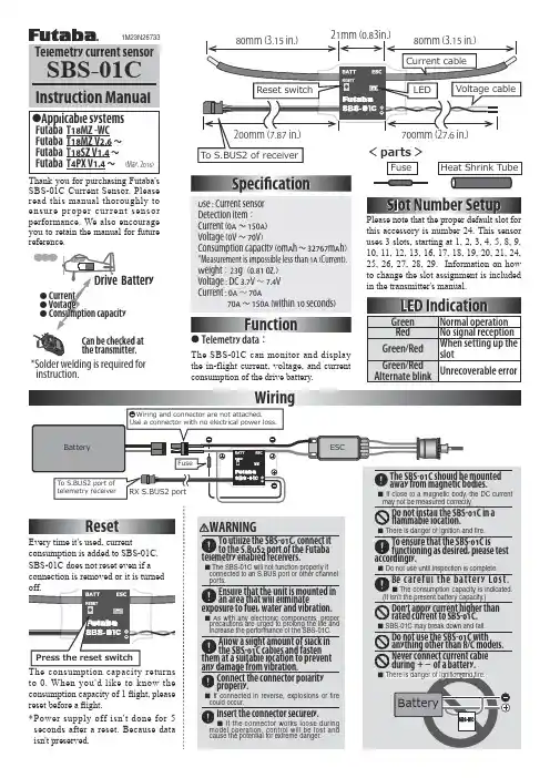
*Solder welding is required for instruction.Slot Number SetupResetFunctionWiringEvery time it's used, currentconsumption is added to SBS-01C.SBS-01C does not reset even if a 80mm (3.15 in.)21mm (0.83in.)Use : Current sensor Detection item :Current (0A ~150A)Voltage (0V ~70V)Consumption capacity (0mAh ~32767mAh)*Measurement is impossible less than 1A (Current).Weight :23g(0.81 oz.)Voltage : DC 3.7V ~7.4V Current : 0A ~70A 70A ~150A (within 10 seconds)Please note that the proper default slot for this accessory is number 24. This sensor uses 3 slots, starting at 1, 2, 3, 4, 5, 8, 9, 10, 11, 12, 13, 16, 17, 18, 19, 20, 21, 24, 25, 26, 27, 28, 29. Information on how to change the slot assignment is included in the transmitter's manual.Telemetry current sensorThank you for purchasing Futaba's SBS-01C Current Sensor. Please read this manual thoroughly to ensure proper current sensor performance. We also encourage you to retain the manual for future reference.●Telemetry data:The SBS-01C can monitor and display the in-flight current, voltage, and current consumption of the drive battery.●Applicable systemsFutaba T18MZ -WC Futaba T18MZ V2.6 ~Futaba T18SZ V1.4 ~Futaba T4PX V1.4 ~Can be checked at the transmitter.(May, 2016)The SBS-01C should be mounted away from magnetic bodies.If close to a magnetic body, the DC current may not be measured correctly.Do not install the SBS-01C in a 昀氀ammable location.There is danger of ignition and fire.To ensure that the SBS-01C isfunctioning as desired, please test Do not use until inspection is complete.②Cut approximately 30mm of the black (-) line from the cable.Solder the fuse inline on the black (-) wire and then reattach the section of wire that was previously removed. The fuse should be attached as close to the external power supply as possible.③ Place a piece of heat shrink tubing over the fuse, ensuring that it covers the soldered areas. Shrink the tubing snug to the fuse and the wire using a heat gun.④ The cable should be connected as shown in the diagram below.⑤ The manual for the Telemetry system should be referred to after the setup is complete. Check to make sure it functions as desired and that it provides the correct data on the display.Fuse to Black line (-)Heat shrink tubeThe connection is affixed to the ESC on the wires that are connected to the battery by soldering them and then protecting them with heat shrink.Fuse(mount in either direction)FUTABA CORPORATION1080 Yabutsuka, Chosei-mura, Chosei-gun, Chiba-ken, 299-4395, JapanPhone: +81 475 32 6982, Facsimile: +81 475 32 6983©FUTABA CORPORATION 2016, 5 (1)。
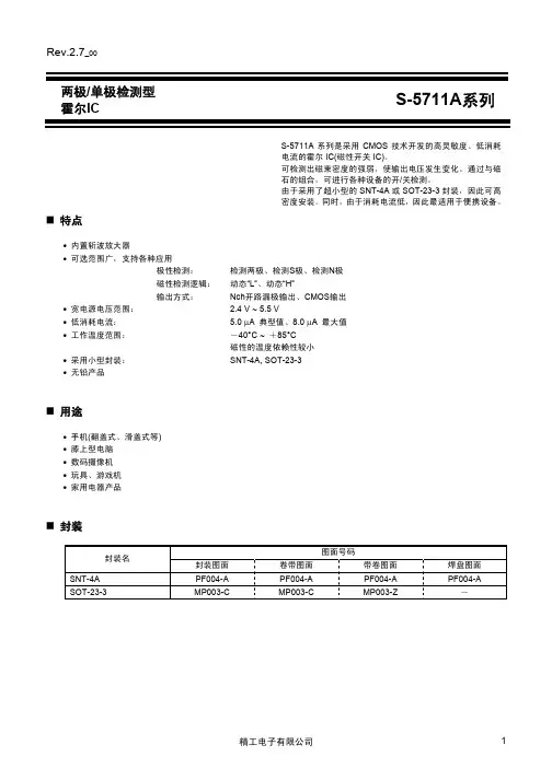
Rev.2.7_00两极/单极检测型S-5711A系列霍尔ICS-5711A系列是采用CMOS技术开发的高灵敏度、低消耗电流的霍尔IC(磁性开关IC)。
可检测出磁束密度的强弱,使输出电压发生变化。
通过与磁石的组合,可进行各种设备的开/关检测。
由于采用了超小型的SNT-4A或SOT-23-3封装,因此可高密度安装。
同时,由于消耗电流低,因此最适用于便携设备。
特点•内置斩波放大器•可选范围广,支持各种应用极性检测:检测两极、检测S极、检测N极磁性检测逻辑:动态“L”、动态“H”输出方式: Nch开路漏极输出、CMOS输出•宽电源电压范围: 2.4 V ~ 5.5 VµA 典型值、8.0 µA 最大值•低消耗电流: 5.0•工作温度范围:-40°C ~ +85°C磁性的温度依赖性较小SOT-23-3•采用小型封装: SNT-4A,•无铅产品用途•手机(翻盖式、滑盖式等)•膝上型电脑•数码摄像机•玩具、游戏机•家用电器产品封装图面号码封装名封装图面卷带图面带卷图面焊盘图面SNT-4A PF004-A PF004-A PF004-A PF004-A-MP003-ZMP003-CSOT-23-3 MP003-C两极/单极检测型霍尔ICS-5711A系列Rev.2.7_00 框图1.Nch开路漏极输出产品OUTVSS*1.寄生二极管图12.CMOS输出产品OUTVSS*1.寄生二极管图2两极/单极检测型霍尔IC Rev.2.7_00S-5711A系列 产品型号的构成1.产品名(1) SNT-4AS-5711 A x x x – I4T1 G封装简称和IC的包装规格*1I4T1 :SNT-4A、卷带产品磁性检测逻辑L :动态“L”H :动态“H”极性检测D :检测两极S :检测S极N :检测N极输出方式N :Nch开路漏极输出C :CMOS输出*1.请参阅卷带图。
(2) SOT-23-3S-5711 A x x x x – M3T1S封装简称和IC的包装规格*1M3T1 :SOT-23-3、卷带产品磁性灵敏度无:B OP = 3.8 mT典型值1 :B OP = 5.0 mT典型值磁性检测逻辑L :动态“L”H :动态“H”极性检测D :检测两极S :检测S极N :检测N极输出方式N :Nch开路漏极输出C :CMOS输出*1.请参阅卷带图。
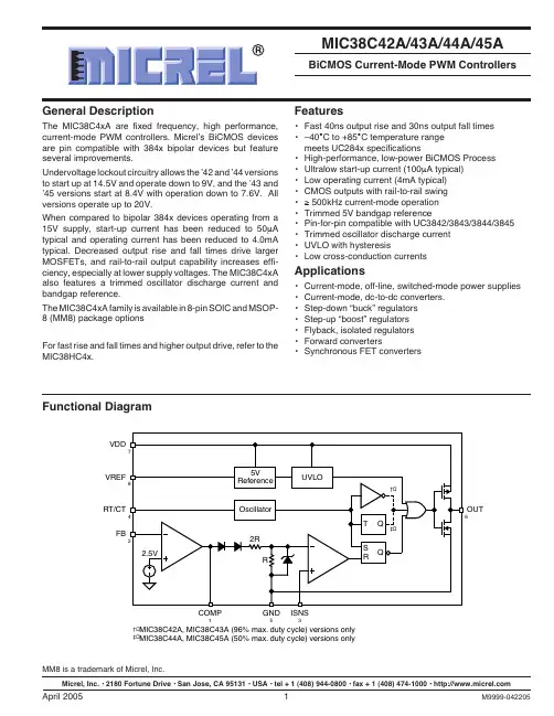
Ordering InformationPart Number TemperatureStandard Pb-Free Range PackageMIC38C42ABM MIC38C42AYM–40°C to +85°C8-pin SOICMIC38C43ABM MIC38C43AYM–40°C to +85°C8-pin SOICMIC38C44ABM MIC38C44AYM–40°C to +85°C8-pin SOICMIC38C45ABM MIC38C45AYM–40°C to +85°C8-pin SOICMIC38C42ABMM MIC38C42AYMM–40°C to +85°C8-pin MM8™MIC38C43ABMM MIC38C43AYMM–40°C to +85°C8-pin MM8™MIC38C44ABMM MIC38C44AYMM–40°C to +85°C8-pin MM8™MIC38C45ABMM MIC38C45AYMM–40°C to +85°C8-pin MM8™Refer to the Part Number Cross Reference for a listings of Micrel devices equivalent to UC284x and UC384x devices.Selection GuideUVLO ThresholdsStartup 8.4V Startup 14.5VDuty Cycle Minimum Operating 7.6V Minimum Operating 9V0% to 96%MIC38C43A MIC38C42A0% to 50%MIC38C45A MIC38C44AElectrical Characteristics (Note 6)V DD = 15V, Note 4; R T = 11.0k; C T = 3.3nF; –40°C ≤ T A ≤ 85°C; unless noted Parameter Test ConditionsMinTypMaxUnitsReference Section Output Voltage T A = 25°C, I O = 1mA 4.905.00 5.10V Line Regulation 12V ≤ V DD ≤ 18V, I O = 5µA 220mV Load Regulation 1 ≤ I O ≤ 20mA 125mV Temp. Stability Note 10.2mV/°C Total Output Variation Line, Load, Temp., Note 14.825.18V Output Noise Voltage 10Hz ≤ f ≤ 10kHz, T A = 25°C, Note 150µV Long Term Stability T A = 125°C, 1000 hrs., Note 1525mV Output Short Circuit –30–80–180mAOscillator Section Initial Accuracy T A = 25°C, Note 5475359kHz Voltage Stability 12 ≤ V DD ≤ 18V0.2 1.0%Temp. Stability T MIN ≤ T A ≤ T MAX , Note 10.04%/°C Clock Ramp T A = 25°C, V RT/CT = 2V, Note 17.78.49.0mA Reset Current AmplitudeV RT/CT peak to peak1.9Vp-pError Amp Section Input Voltage V COMP = 2.5V 2.42.50 2.58V Input Bias Current V FB = 5.0V –0.1–2µA A VOL2 ≤ V O ≤ 4V 6590dB Unity Gain Bandwidth Note 10.7 1.0MHz PSRR12 ≤ V DD ≤ 18V60dB Output Sink Current V FB = 2.7V, V COMP = 1.1V 214mA Output Source Current V FB = 2.3V, V COMP = 5V –0.3–1mA V OUT High V FB = 2.3V, R L = 15k to ground 56.8V V OUT LowV FB = 2.7V, R L = 15k to V REF0.11.1VAbsolute Maximum RatingsSupply Voltage (V DD )....................................................20V Switch Supply Voltage (V D )..........................................20V Current Sense Voltage (V ISNS ).....................–0.3V to 5.5V Feedback Voltage (V FB )................................–0.3V to 5.5V Output Current (I OUT )...................................................0.5A Storage Temperature (T A ).......................–65°C to +150°COperating RatingsJunction Temperature (T J )........................................150°C Package Thermal Resistance8-Pin MM8™ (θJA ).............................................250°C/W 8-Pin SOIC (θJA )...............................................170°C/WParameter Test ConditionsMinTypMaxUnitsCurrent Sense GainNotes 2, 32.853.0 3.15V/V MaximumThreshold V COMP = 5V, Note 20.91 1.1V PSRR12 ≤ V DD ≤ 18V, Note 270dBInput Bias Current –0.1–2µA Delay to Output 120250nsOutput R DS(ON) High I SOURCE = 200mA 20ΩR DS(ON) Low I SINK = 200mA 11ΩRise Time T A = 25°C, C L = 1nF 4080ns Fall TimeT A = 25°C, C L = 1nF3060nsUndervoltage Lockout Start ThresholdMIC38C42A/4A 13.514.515.5V MIC38C43A/5A7.88.49.0V Minimum Operating VoltageMIC38C42A/4A 8910V MIC38C43A/5A7.07.68.2VPulse Width Modulator Maximum Duty CycleMIC38C42A/3A 9496%MIC38C44A/5A4650%Minimum Duty Cycle 0%Total Standby Current Start-Up CurrentV DD = 13V for MIC38C42A/44A 100230µA V DD = 7.5V for MIC38C43A/45A Operating Supply CurrentV FB = V ISNS = 0V4.06.0mANote 1:These parameters, although guaranteed, are not 100% tested in production.Note 2:Parameter measured at trip point of latch with V EA = 0.Note 3:Gain defined as:A =V V (I )0 V (I ) 0.8VPIN1TH SNS TH SNS ∆;≤≤Note 4:Adjust V DD above the start threshold before setting at 15V.Note 5:Output frequency equals oscillator frequency for the MIC38C42 and MIC38C43. Output frequency for the MIC38C44A, andMIC38C45A equals one half the oscillator frequency.Note 6:Specification for packaged product only.。
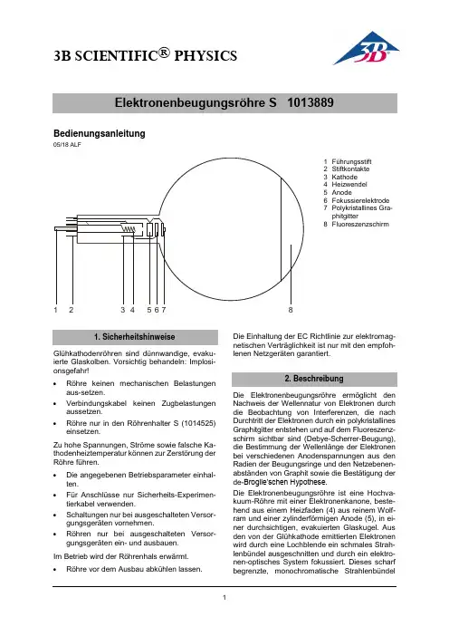
3B SCIENTIFIC ® PHYSICS1Bedienungsanleitung05/18 ALF1 Führungsstift2 Stiftkontakte3 Kathode4 Heizwendel5 Anode6 Fokussierelektrode 7Polykristallines Gra-phitgitter8 FluoreszenzschirmGlühkathodenröhren sind dünnwandige, evaku-ierte Glaskolben. Vorsichtig behandeln: Implosi-onsgefahr!∙ Röhre keinen mechanischen Belastungen aus-setzen.∙ Verbindungskabel keinen Zugbelastungen aussetzen.∙Röhre nur in den Röhrenhalter S (1014525) einsetzen.Zu hohe Spannungen, Ströme sowie falsche Ka-thodenheiztemperatur können zur Zerstörung der Röhre führen.∙ Die angegebenen Betriebsparameter einhal-ten.∙ Für Anschlüsse nur Sicherheits-Experimen- tierkabel verwenden.∙ Schaltungen nur bei ausgeschalteten Versor-gungsgeräten vornehmen.∙Röhren nur bei ausgeschalteten Versor-gungsgeräten ein- und ausbauen. Im Betrieb wird der Röhrenhals erwärmt.∙Röhre vor dem Ausbau abkühlen lassen.Die Einhaltung der EC Richtlinie zur elektromag-netischen Verträglichkeit ist nur mit den empfoh-lenen Netzgeräten garantiert.Die Elektronenbeugungsröhre ermöglicht den Nachweis der Wellennatur von Elektronen durch die Beobachtung von Interferenzen, die nach Durchtritt der Elektronen durch ein polykristallines Graphitgitter entstehen und auf dem Fluoreszenz-schirm sichtbar sind (Debye-Scherrer-Beugung), die Bestimmung der Wellenlänge der Elektronen bei verschiedenen Anodenspannungen aus den Radien der Beugungsringe und den Netzebenen-abständen von Graphit sowie die Bestätigung der de-Broglie’schen Hypothese.Die Elektronenbeugungsröhre ist eine Hochva-kuum-Röhre mit einer Elektronenkanone, beste-hend aus einem Heizfaden (4) aus reinem Wolf-ram und einer zylinderförmigen Anode (5), in ei-ner durchsichtigen, evakuierten Glaskugel. Aus den von der Glühkathode emittierten Elektronen wird durch eine Lochblende ein schmales Strah-lenbündel ausgeschnitten und durch ein elektro-nen-optisches System fokussiert. Dieses scharf begrenzte, monochromatischeStrahlenbündel12345678geht durch ein feines Nickeldrahtgeflecht (7), das mit einer polykristallinen Graphitfolie belegt ist und als Beugungsgitter wirkt. Auf dem Fluores-zenzschirm (8) ist das Beugungsbild als zwei konzentrische Ringe um den ungebeugten Elekt-ronenstrahl sichtbar.Ein Magnet ist Bestandteil des Lieferumfangs. Er ermöglicht eine Richtungsänderung des Elektro-nenstrahls, die notwendig wird, wenn er auf eine fertigungsbedingte oder durch Verglühen ent-standene Fehlstelle des Graphitgitters trifft.Heizung: ≤ 7,0 V AC/DC Anodenspannung: 0 – 5000 V DC Anodenstrom: typ. 0,15 mA bei4000 V DC Gitterkonstanten von Graphit: d10 = 0,213 nmd11 = 0,123 nm Abmessungen:Abstand Graphitgitter/Fluoreszenzschirm: ca. 125 ± 2 mm Fluoreszenzschirm: ca. 100 mm Ø Glaskolben: ca. 130 mm Ø Gesamtlänge: ca. 260 mmZur Durchführung der Experimente mit der Elek-tronenbeugungsröhre sind folgende Geräte zu-sätzlich erforderlich:1 Röhrenhalter S 1014525 1 Hochspannungsnetzgerät, 5 kV(115 V, 50/60 Hz) 1003309 oder(230 V, 50/60 Hz) 1003310 1 Analog Multimeter AM51 10030744.1 Einsetzen der Elektronenbeugungsröhrein den Röhrenhalter∙Röhre mit leichtem Druck in die Fassung des Röhrenhalters schieben bis die Stiftkontakte vollständig in der Fassung sitzen, dabei auf eindeutige Position des Führungsstiftes ach-ten.4.2 Entnahme der Elektronenbeugungsröhreaus dem Röhrenhalter∙Zum Entnehmen der Röhre mit dem Zeigefin-ger der rechten Hand von hinten auf den Füh-rungsstift drücken bis sich die Kontaktstifte lösen. Dann die Röhre entnehmen.4.3 Allgemeine HinweiseDie Graphitfolie auf dem Beugungsgitter ist nur wenige molekulare Schichten dick und kann des-halb durch einen Strom über 0,2 mA zerstört wer-den.Während des Versuchs ist der Anodenstrom so-wie die Graphitfolie zu kontrollieren. Bei aufglü-hendem Graphitgitter oder Emissionsstrom grö-ßer 0,2 mA ist die Verbindung zur Anodenspan-nung sofort zu unterbrechen.Bei unbefriedigenden Beugungsringen kann die Richtung des Elektronenstrahls mit Hilfe des Magneten so geändert werden, dass er auf eine andere Stelle der Grafitfolie trifft.∙Versuchsaufbau gemäß Fig. 2 herstellen.∙Heizspannung anlegen und ca. 1 Minute war-ten bis die Heizleistung stabil ist.∙Anodenspannung von 4 kV anlegen.∙Durchmesser D der Beugungsringe auf dem Leuchtschirm bestimmen.Auf dem Fluoreszenzschirm sind zwei Beu-gungsringe um den ungebeugten Elektronen-strahl sichtbar. Jeder der beiden Ringe entspricht einer Bragg’schen Reflexion an den Atomen ei-ner Netzebene des Graphits.Veränderungen der Anodenspannung bewirken eine Veränderung der Durchmesser der Beu-gungsringe, wobei eine Verringerung der Span-nung eine Vergrößerung des Durchmessers be-wirkt. Diese Beobachtung steht im Einklang mit de Broglies Postulat, dass sich die Wellenlänge verlängert mit einer Abnahme des Impulses.a) Bragg-Gleichung: ϑ⋅⋅=λsin2dλ = Wellenlänge der Elektronenϑ = Glanzwinkel des Beugungsringesd = Netzebenenabstand im GraphitgitterL = Abstand zwischen Probe und LeuchtschirmD = Durchmesser der BeugungsringeR = Radius der BeugungsringeLD⋅=ϑ22tanLRd⋅=λb) de-Broglie-Gleichung:ph=λh = Plancksches Wirkungsquantump = Impuls der ElektronenmpUe⋅=⋅22Uemh⋅⋅⋅=2λm = Elektronenmasse, e = Elementarladung23B SCIENTIFIC ® PHYSICS3B Scientific GmbH ▪ Ludwig -Erhard-Str. 20 ▪ 20459 Hamburg ▪ Deutschland ▪ Technische Änderungen vorbehalten © Copyright 2022 3B Scientific GmbHFig. 1 Schematische Darstellung zur Debye-Scherrer-BeugungFig. 2 Beschaltung der Elektronenbeugungsröhre。

SEC霍尔线性器件SS49E使用手册
~ 1 ~
SEC 霍尔线性器件SS49E 产品使用手册
概述:
SS49E 线性霍尔效应传感器是一款体积小,功能多的线性霍尔效应器件,它在永久磁体或电磁体产生的磁场控制下工作。
线性输出电压由电源电压设置并随磁场强度的变化而等比例改变。
先进的内置功能电路设计确保了它的低输出噪声,从而使得该器件的使用无需搭配外部滤波电路。
内置薄膜电阻大大增强了器件的温度稳定性和输出精度。
其工作温度范围宽达-40°C 到150°C ,适用于绝大多数的消费、商业及工业应用。
该器件提供了小外形利用Transis-TOR (SOT ),或在塑料单列直插(SIP3L 平),两个3引脚封装均符合RoHS 标准。
优点和特性:
– 4.5V 到6V 的工作电压范围
–微型系统架构
–低噪声输出
–磁优化封装
–准确的线性输出为外围电路的设计提供了更多灵活性
–工作温度范围宽达-40°C 到150°C
应用实例:
–汽车控制
–磁码读取
–含铁金属探测
–电流检测
–位置探测
封装:
3引脚的SOT23封装 (器件标号后缀为SO) ; 3引脚的
SIP 封装
(器件标号后缀为UA)。

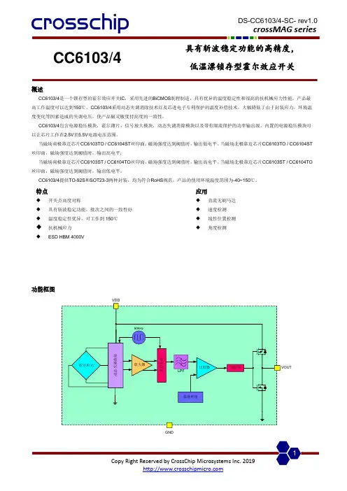
CC6103/4具有斩波稳定功能的高精度, 低温漂锁存型霍尔效应开关概述CC6103/4是一个锁存型的霍尔效应开关IC ,采用先进的BiCMOS 制程制造,具有优异的温度稳定性和很高的抗机械应力性能,产品最高工作温度可以达到150℃。
CC6103/4采用动态失调消除技术以及芯进电子专利保护的温度补偿技术,大幅降低了由于封装应力,环境温度变化等因素造成的失调电压,使产品磁灵敏度持高度的一致性。
CC6103/4包含电源稳压模块,霍尔薄片,信号放大模块,动态失调消除模块以及带有限流保护的功率输出级。
内置的电源稳压模块可以让芯片工作在2.5V 至5.5V 电源电压范围。
当磁场南极靠近芯片CC6103TO / CC6104ST 丝印面,磁场强度达到阈值时,输出低电平。
当磁场北极靠近芯片CC6103TO / CC6104ST 丝印面,磁场强度达到阈值时,输出高电平;当磁场南极靠近芯片CC6103ST / CC6104TO 丝印面,磁场强度达到阈值时,输出高电平。
当磁场北极靠近芯片CC6103ST / CC6104TO 丝印面,磁场强度达到阈值时,输出低电平。
CC6103/4提供TO-92S 和SOT23-3两种封装,均为符合RoHS 规范,产品的使用环境温度范围为-40~150℃。
功能框图动态失调消除放大器预驱动采样保持比较器50KHzLPF基准电压霍尔单元GND特点◆ 开关点高度对称◆ 具有斩波稳定功能,批次之间的一致性好 ◆ 温度稳定性优异,可工作到150℃ ◆ 抗机械应力◆ ESD HBM 4000V 应用◆ 直流无刷马达 ◆ 速度检测 ◆ 线性位置检测 ◆角度检测名称 封装型号 备注 CC6103TO TO-92S 袋装,1000片/包 CC6103ST SOT23-3 卷盘,3000片/卷 CC6104TO TO-92S 袋装,1000片/包 CC6104STSOT23-3卷盘,3000片/卷开关输出 vs. 磁场极性VoutS poleV OHV OLB HB RPB OPN pole CC6103TO / 6104STVoutN poleV V OL 0B HB RP B OPS poleCC6103ST / 6104TO注意: 磁场加在芯片的丝印面管脚描述CC6103XXYYWW132V DD V OUTGND1236103V DDGND V OUTCC6104XXYYWW132V DD V OUTGND1236104V DDGNDV OUT名称 管脚编号 功能 TO-92SSOT23-3V DD 1 1 电源电压 GND 2 3 地 V OUT32输出参数符号数值单位电源电压V DD-0.3~5.5 V输出脚耐压V OUT-0.3~VDD+0.3 V磁场强度 B 无限制Gauss工作环境温度T A-40~150 ℃存储环境温度Ts -50至160 ℃ESD(HBM) 4000 V电气参数参数符号测试环境最小值典型值最大值单位电源电压V DD- 2.5 - 5.5 V静态电流I DD25℃,V DD=5.0V - 2 3 mA输出电流I OUT25℃,V DD=5.0V,纯阻性负载- - 50 mA 输出饱和压降V SAT25℃,I OUT=50mA - - 0.4 V上升时间tr R L=820Ω,C L=10pF - 1.0 - us下降时间tf R L=820Ω,C L=10pF - 2.5 - us磁参数参数符号测试环境最小值典型值最大值单位工作点B OP25℃15 30 45 Gauss释放点B RP25℃-45 -30 -15 Gauss迟滞B HYS25℃50 60 70 Gauss 典型应用电路静态电流vs. 工作电压磁感应点vs. 工作电压磁感应点vs. 温度封装信息(1)TO-92S package0.730.414.093.0214.991.270.431.02MAXHall 感应点位置1.442.01CC6103打标信息: 第一行: CC6103-产品名称 第二行: XXYYWW XX – 代码YY – 封装年份的后两位数 WW – 封装时的星期数CC6104打标信息: 第一行: CC6104-产品名称第二行: XXYYWW XX – 代码YY – 封装年份的后两位数 WW – 封装时的星期数注意: 所有单位均为毫米。
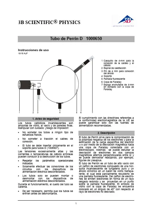
3B SCIENTIFIC® PHYSICSInstrucciones de uso10/15 ALF1 Casquillo de 4-mm paralaconexión de la caldeo y elcátodo2 Espiral de calefacción3 Pin de4 mm para conexióndel ánodo4 Soporte5 Pantalla fluorescente6 Copa de Faraday7 Espiga enchufable de 4-mmen contacto con la copa deFaradayampollas de vidrio, al vacío y de paredes finas.Manipular con cuidado: ¡riesgo de implosión!∙No someter los tubos a ningún tipo de esfuerzos físicos.∙No someter a tracción el cables de conexión.∙El tubo se debe insertar únicamente en el soporte para tubos D (1008507).Las tensiones excesivamente altas y las corrientes o temperaturas de cátodo erróneas pueden conducir a la destrucción de los tubos. ∙Respetar los parámetros operacionales indicados.∙Solamente efectuar las conexiones de los circuitos con los dispositivos de alimentación eléctrica desconectados.∙Lostubos solo se pueden montar o desmontar con los dispositivos de alimentación eléctrica desconectados. Durante el funcionamiento, el cuello del tubo se calienta.∙De ser necesario, permita que los tubos se enfríen antes de desmontarlos. El cumplimiento con las directrices referentes a la conformidad electromagnética de la UE se puede garantizar sólo con las fuentes de alimentación recomendadas.la polaridad negatica de los electrones y para la estimación de la carga específica del electrón e/m por medio de la desviación magnética hacia una copa de Faraday conectada con un electroscopio. Además se puede estudiar la desviación de electrones en dos campos magnéticos alternos perpendiculares entre sí y se puede demostrar realizando, por ejemplo, figuras de Lissajous.El tubo de Perrón es un tubo de alto vacío con un cañon de electrones compuesto de una hor-quilla incandescente de tungsteno puro y un ánodo cilíndrico en un balón de vidrio transpa-rente, el cual está parcialmente recubierto de una pantalla fluorescente. Del cañon de electro-nes se emiten electrones en forma de un rayo delgado redondo y se proyectan en un punto sobre la pantalla fluorescente. El embolo de vidrio con la copa de Faraday se encuentra colocado en un ángulo de 45° con respecto al rayo de electrones no desviado.Tensión de caldeo: ≤ 7,5 V CA/CC Tensión anódica: 2000 V - 5000 V Corriente anódica: típ. 1,8 mA conU A = 4000 V Corriente del rayo: 4 µA conU A = 4000 V Ampolla de vidrio: aprox. 130 mm Ø Longitud total: aprox. 260 mmde Perrin se requieren adicionalmente los siguientes aparatos:1 Soporte de tubos D 1008507 1 Fuente de alta tensión 5 kV (115 V, 50/60 Hz)1003309 o1 Fuente de alta tensión 5 kV (230 V, 50/60 Hz)1003310 1 Par de bobinas de Helmholtz S 1000611 1 Fuente de alimentación de CC, 20 V, 5 A (115 V, 50/60 Hz) 1003311 o1 Fuente de alimentación de CC, 20 V, 5 A (230 V, 50/60 Hz) 1003312 1 Electroscopio 1001027 1 Multímetro analogico AM50 1003073Se recomienda adicionalmente:Adaptador de protección, de 2 polos 10099614.1 Instalación del tubo en el soporte paratubo∙Montar y desmontar el tubo solamente con los dispositivos de alimentación eléctrica desconectados.∙Retirar hasta el tope el desplazador de fijación del soporte del tubo.∙Colocar el tubo en las pinzas de fijación.∙Fijar el tubo en las pinzas por medio del desplazador de fijación.∙Dado el caso, se inserta el adaptador de pro-tección en el casquillo de conexión del tubo.4.2 Desmontaje del tubo del soporte paratubo∙Para retirar el tubo, volver a retirar el desplazador de fijación y extraer el tubo.corpuscular de los rayos catódicos y determinación de su polaridad∙Realice el cableado se acuerdo con la fig. 1. ∙Aplique una tensión de ánodo entre 3 kV y 5 kV. En la pantalla fluorescente se hacen visibles los rayos catódicos en forma de un punto redondo.∙Por medio de las bobinas de Helmholtz se desvían los rayos catódicos de tal forma que incidan exactamente sobre la copa de Faraday.Alternativamente se puede desviar el rayo por medio de un imán colocado en la horquilla.La aguja del electroscopio se desvía y muestra una carga.∙Se desconectan las tensiones de caldeo y de ánodo.∙La desviación del electroscopio se mantiene. Si la carga de la copa de Faraday se originara de-bido a una radiación de ondas, la desviación del electroscopio retornaría a cero en el momento de desconectar la tensión de caldeo. Como éste no es el caso, se puede deducir que los rayos catódicos se componen de materia que está cargada electricamente. Estas partículas son los electrones. La polaridad negativa de los rayos catódicos se puede comprobar por medio de una carga ulterior del electroscopio, ya sea por medio de una barra de plástico frotada o una de vidrio (negativo resp. positivo).5.2 Estimación de la carga específica delelectrón e/m∙Realice el cableado de acuerdo con la fig. 3. En la desviación de los rayos de electrones en la copa de Faraday se tiene para la carga específica e/m:()22rBUme A⋅⋅=(1)U A se puede leer inmediatamente, el radio de curvatura r se obtiene de los datos geométricos del tubo (diámetro del émbolo 13 cm, copa de Faraday inclinada 45° con respecto al eje del rayo no desviado) asi´ es r = aprox. 16 cm (ver Fig 2). Para la densidad del flujo magnético B del campo en la geometría de Helmholtz del par de bobinas y con una corriente de bobinas I, se tiene:IkIRnB⋅=⋅⋅μ⋅⎪⎭⎫⎝⎛=02354(2)con k = en buena aproximación 4,2 mT/A, n = 320 (espiras) y R = 68 mm (Radio de las bobinas).∙Se calcula e/m después de sustituir los los valores para U A, r y B en la ecuación 1.5.3 Desviación en campos magneticosalternos cruzados (figuras de Lissajous) Se requieren adicionalmente los siguientes aparatos:1 Bobina adicional 1000645 1 Fuente de alimentación CA/CC 12 V,3 A (115 V, 50/60 Hz) 1002775 o1 Fuente de alimentación CA/CC 12 V,3 A (115 V, 50/60 Hz) 10027761 Generador de funciones FG100 (115 V, 50/60 Hz) 1009956 o1 Generador de funciones FG100 (230 V, 50/60 Hz) 1009957 ∙ Realice el cableado de acuerdo con la fig. 4. ∙ Se coloca la bobina adicional en la horquillasuperior del soporte de tubo. El pasador de fijación se desplaza sobre el retén labial de la bobina y así se fija.∙ Se conecta la bobina adicional a la fuentede tensión alterna.∙Se conectan las bobinas de Helmholtz al generador de funciones y se selecciona una señal senoidal.∙ Se aplica una tensión de ánodo entre 3 kV y 5 kV.∙Se selecciona una tensión alterna senoidal de hasta 15 V en la bobina adicional y se observa la desviación horizontal.∙Se ajusta por ejemplo una frecuencia de 50 Hz en el generador de funciones, se va-ría la amplitud de la señal senoidal y se ob-servan las figuras de Lissajous en la pan-talla fluorescente.Fig. 1 Comprobación de la naturaleza corpuscular de los rayos catódicos y determinación de su polaridadFig. 2 Determinación de rFig. 3 Estimación de la carga específica del electrón e/mFig.4 Desviación en campos magneticos alternos cruzados (figuras de Lissajous)3B Scientific GmbH ▪ Rudorffweg 8 ▪ 21031 Hamburgo ▪ Alemania ▪ 。
F eat eatu u r es a n d B e n ef efii ts – 4.5V to 24V Operation–-40℃to 150℃Superior temperature operation –Bipolar technology–Open-collector 25mA output –Reverse battery protection–Small Size-SOT233L or SIP 3L–Solid-state reliability–Resistant to physical stress–Activatewith small,commercially available permanent magnets3pin SOT23(suffix SO)3pin SIP (suffix UA)A p p li licat cat cati i o n Exa Examm p l es –Brushless DC motor commutation –Automotive,Consumer and Industrial –Solid-state switch –Speed measurement –Revolution counting–Angular position detection –Proximity detectionGeneral DescriptionThe SS41is an integrated Hall effect latched sensor designed for electronic commutation of brush-less DC motor applications.The device integrates a voltage regulator, reverse battery protection diode,Hall sensor with dynamic offset cancellation system,temperature compensation circuitry,small signal amplifier,Schmitt trigger and an open-collector output to sink up to25mA.These Hall-effect switches are monolithic integrated circuits with tighter magnetic specifications,designed to operate continuously over extended temperatures to+150℃,and are more stable with both temperature and supply voltage changes.If a magnetic flux density larger than threshold Bop, Output is turned on(low).The output state is held until a magnetic flux density reversal falls below Brp,causing Output to be turned off(high).Thanks to its wide operating voltage range and extended choice of temperature range,it is quite suitable for use in DC motor applications.The device is delivered in a Small Outline Transistor(SOT) or in a Plastic Single In Line(SIP3L flat).Both3-lead packages are RoHS compliant.Glossary of TermsMilliTesla(mT),Units of magnetic flux density:1mT=10GaussRoHS Restriction of Hazardous SubstancesOperating Point(B OP)Magnetic flux density applied on the branded side of the package which turns the output driver ON(V OUT=V DSon)Release Point(B RP)Magnetic flux density applied on the branded side of the package which turns the output driver OFF(V OUT=high)escr r i p t i on ons sP i n D e f i n i t i on ons s a n d D escSOT Pin№SIP Pin№Name Type Function11VDD Supply Supply Voltage pin23OUT Output Open Drain Output pin32GND Ground Ground pinAbs s o l u te M ax axi i m u m R at ati i ng ngs sAbParameter Symbol Value UnitsSupply Voltage V DD28VSupply Current I DD50mAOutput Voltage V OUT28VOutput Current I OUT50mAStorage Temperature Range T S-65to170°CAbsolute maximum ratingsOperating Temperature Range Symbol Value UnitsTemperature Suffix“E”TA-40to85°CTemperature Suffix“K”TA-40to125°CTemperature Suffix“L”TA-40to150°CExceeding the absolute maximum ratings may cause permanent damage.Exposure to absolute-maximum-rated conditions for extended periods may affect device reliability.Ge Gen n e r al E l ec ect t ri ric c al S p ec eci i f i cat cati i on onss DC Operating Parameters T A =25℃,V DD =4.5V to 24V (unless otherwise specified)Parameter Symbol Test Conditions Min TypMax Units Supply Voltage V DD Operating 4.524V Supply Current I DD B <B RP510mA Output Saturation Voltage V DSon I OUT =20mA,B >B OP 0.40.5V Output Leakage Current I OFF B <B RP V OUT =24V 0.015µA Output Rise Time t r R L =1KΩ,C L =20pF 0.3 1.5µs Output Fall Timet fR L =1KΩ,C L =20pF0.3 1.5µsM a gn gnet et eti i c S p e c i f i c at ati i on onss DC Operating Parameters V DD =4.5V to 24V (unless otherwise specified)Parameter Symbol Test ConditionsMin Typ Max Units Operating Point B OP Ta=25℃,Vdd=5V DC53770G Release Point B RP -70-37-5G HysteresisB HYS75GApp Appli li licat cat cati i o n I n f or ormat mat matii o nmat t io ion n Packag g e I n f o r ma PackaPackage F,3-Pin SIP:Package FTFT,,3-Pin SOT-23:Ordering InformationPart No.Pb-free Temperature Code Package Code PackingSS41ESOT YES-40°C to85°C SOT-237-in.reel,3000pieces/reel SS41EUA YES-40°C to85°C TO-92Bulk,1000pieces/bag SS41KSOT YES-40°C to125°C SOT-237-in.reel,3000pieces/reel SS41KUA YES-40°C to125°C TO-92Bulk,1000pieces/bag SS41LSOT YES-40°C to150°C SOT-237-in.reel,3000pieces/reel SS41LUA YES-40°C to150°C TO-92Bulk,1000pieces/bag。
CS3144霍尔开关电路CS3144霍尔开关集成电路应用霍尔效应原理,采用半导体集成技术制造的磁敏电路,它是由电压调整器、霍尔电压发生器、差分放大器、史密特触发器,温度补偿电路和集电极开路的输出级组成的磁敏传感电路,其输入为磁感应强度,输出是一个数字电压讯号。
此款电路管腿采用纯锡制作,产品完整型号为CS3144EUA-S 或者CS3144LUA-S 。
产品特点 . 体积小 . 灵敏度高 . 响应速度快 . 温度性能好 . 精确度高 . 可靠性高ACC配套磁钢2CS3144霍尔开关电路3特征曲线磁场强度(m T )输出饱和电压 (m V )4CS3144霍尔开关电路5印章说明包装说明: 袋装: 500只/袋盒装: 5000只(10袋 )/盒使用须知:HALL IC 是一种敏感器件,除了对磁敏感外,对光、热、机械应力均有不同程度的敏感,因此在使用过程中,应注意如下几点:◆ 机械应力:由于机械应力会造成Hall IC 磁敏感度的漂移,在使用安装中应尽量减少施加到IC 外壳和引线上的机械应力,引线根部3mm 以内不得弯曲,其余部分弯曲时必须将引线根部夹住,以防对内引线的影响,降低可靠性。
◆ 热应力:为避免Hall IC 的非正常损坏,焊接时,温度应低于260℃,时间少于4秒,焊接点距离IC 引线上根部3mm 以外。
◆ Hall IC 的工作电压不得超过说明书规定的Vcc ,大部分Hall IC 开关均为OC 输出。
因此,输出应接负载电阻R L ,如图(1),R L 的值取决于负载电流I OL 的大小,不得超负载使用。
◆ 由于Hall IC 是一种敏感器件,因此,它的磁感度在高、低温下的一定漂移是正常的。
一般情况下T 变化±60℃,温漂应不高于30GS (高温IC 不大于15GS )。
因此,在磁路设计时,应放出一定的磁灵敏度余量,即作用于IC 表面磁场强度应高于实际B H-L 50GS 左右,如图(2)。
~ 1 ~ SEC 单极霍尔开关SS441使用手册-中文
概述:
SS441是一个采用双极晶体管技术制造的单极霍尔效应传感器IC 。
该器件集成了电压调节器、反向电池保护二极管、带动态偏移消除系统的霍尔传感器、温度补偿电路、小信号放大器、施密特触发器和一个输出灌电流达25mA 的集电极开漏输出驱动器。
配合以适当的上拉输出电路,它即可与双极型晶体管电路或CMOS 逻辑电路器件协同工作。
优点和特性:
- 4.5V 到24V 的工作电压范围
- -40°C 到150°C 的极大的工作温度范围
- 双极晶体管工艺
- 集电极开漏25mA 输出
- 反向电池保护
- 小尺寸SOT23 3L 或者SIP 3L 封装
- 高固态可靠性
- 抗物理应力
应用实例:
- 汽车、消费类电子及工业级应用
- 固态开关
- 无刷直流电机
- 速度检测
- 线性位置检测
- 角度检测
- 近感探测
- 电流检测
封装:
3引脚的SOT23封装 (器件标号后缀为SO) ; 3引脚的
SIP 封装
(器件标号后缀为UA)。
S18-L242B-2使用说明书V1.0Mini SMD Digital Pyroelectric Infrared SensorsMINI SMD 数字型热释电红外传感器森霸传感科技股份有限公司Senba Sensing Technology Co.,Ltd. MINI SMD 数字型热释电红外传感器MINI SMD 数字型热释电红外传感器When PIR signal is above the triggered threshold, there will be a count impulse inside. And when PIR sensor receives this impulse signal, it will think this signal as the second impulse. Once the second impulse was received within 4S, the PIR sensor will alarm, meanwhile, the REL pin will be triggered.Besides, when the PIR signal is above 5 times of the triggered threshold, only one impulse is enough to trigger REL output as below. For multiple triggers, the delay time of REL output begins from the last valid trigger.Ⅶ The Output Trigger ModeⅥ Working Conditions (T=25°C, Vdd=3V,Except other requirements) Characteristics SymbolMin Type Max.Unit RemarksSupply Voltage V DD 2.23 3.7V Working Current I DD 99.511μA Sensitivity V SENS 90μV Non-adiustable Output RELOutput Low Current I OL 10mA VOL<1VOutput High Current I OH -10mA VOH>(VDD-1V)Low REL output locking time T OL 2.3s Non-adiustableHigh REL output delay time T OH 2.33600s SENS/ONTIME Input voltage0VDD/2V 0V to VDD/2Input Bias Current-11μA Oscillator &Band Pass Filter(BPF)Band Pass Filter(BPF) Low cut-off frequency7Hz Band Pass Filter(BPF) High cut-off frequency0.44Hz Oscillator frequency on Chip F CLK64kHzMini SMD Digital Pyroelectric Infrared SensorsMINI SMD 数字型热释电红外传感器When the motion signal is detected, there will be a REL output. A voltage applied to the ONTIME input set the time the REL output is active with a single trigger event. Any REL output signal will reset the REL ONTIME, and re-timing again.In analog REL mode, connect ONTIME Pin to voltage with a resistance which could adjust in 100 KΩ~510 KΩ. In analog mode, the ONTIME pin will have a corresponding oscillation frequency, the analog time delay Td=230400/f, f is the oscillation frequency. For more time delay, the ONTIME Pin can connect one more capacity GND except resistance. Capacitor should be selected according to different requirements, but the capacitance value ≤10nF, and the resistance value between 100K to 510KΩ.The operating current is inversely proportional to the selected resistance R. The larger the resistance value, the smaller the operating current. If the power consumption requirement is high, it is recommended to use a larger resistor (300K-510K) or a digital REL timing mode. To obtain accurate timing time, select the appropriate capacitor resistance value, first calculate the timing time according to the oscillation frequency, and then adjust the capacitor resistance parameter.Ⅷ ONTIME SettingMini SMD Digital Pyroelectric Infrared SensorsMINI SMD数字型热释电红外传感器Diagram 1 ONTMIE Pin without CapacityDiagram 2 ONTMIE Pin with 10pF CapacityDiagram 3 ONTMIE Pin with 560pFCapacity GNDD i a g r a m 4 O N T M IE P i n w i t h 1n FCapacity GNDThe operating current is inversely proportional to selected resistance. The average consumed current of resistance during REL validity period is: IR 0.75VDD/R. During REL invalidity period, the resistance has no consumption. For high consumption and always REL validity, the digital REL is recommended. 2. In digital REL mode, ONTIME Pin connect with a fixed potential less than VDD/2(in application, the REL can adjust by adopting resistance divider). It is better to make the RH is 1MΩ. The REL output retention time is set by input voltage of ONTIME through the only trigger. The output time delayMini SMD Digital Pyroelectric Infrared SensorsMINI SMD 数字型热释电红外传感器Ⅸ Reliable TestNumber Time Td(s)ONTIME Voltage Range (VDD)ONTIMEVoltageCentral Value (VDD)Recommend Divider Resistance (±0.1%)resistance-highresistance-low120~1/32VDD 1/64VDD 1M 0R 251/32VDD~2/32VDD 3/64VDD 1M 51K 3102/32VDD~3/32VDD 5/64VDD 1M 82K 4153/32VDD~4/32VDD 7/64VDD 1M 124K 5204/32VDD~5/32VDD 9/64VDD 1M 165K 6305/32VDD~6/32VDD 11/64VDD 1M 210K 7456/32VDD~7/32VDD 13/64VDD 1M 255K 8607/32VDD~8/32VDD 15/64VDD 1M 309K 9908/32VDD~9/32VDD 17/64VDD 1M 360K 101209/32VDD~10/32VDD 19/64VDD 1M 422K 1118010/32VDD~11/32VDD 21/64VDD 1M 487K 1230011/32VDD~12/32VDD 23/64VDD 1M 560K 1360012/32VDD~13/32VDD 25/64VDD 1M 634K 1490013/32VDD~14/32VDD 27/64VDD 1M 732K 15180014/32VDD~16/32VDD 29/64VDD 1M 825K 16360015/32VDD~16/32VDD31/64VDD1M953KTestStandardTest Result Salt spray testGB/T 10125-2012OK High temperature test 100℃,500 hours OK Low temperature test -40℃,500 hoursOK HumidityRelative humidity 95%, 500 hours OK Heat resistance 250℃,10SOK Vibration Frequency: 10Hz-55H, Time: 2 hours OK Fall 1m free fall OKMINI SMD数字型热释电红外传感器lens name:SB-F-11单位:mmMini SMD Digital Pyroelectric Infrared SensorsMINI SMD 数字型热释电红外传感器Widely used in human bodysensor switches, alarms, infrared testers, smart-house appliances, and household appliances, it can provide users Fresnel lenses with different sensing angles, sensing distances and sizes.Standard package: 1000pcs. According to different model types,the quantity and size of the packages will change slightly.Unit: mm:Mini SMD Digital Pyroelectric Infrared SensorsMINI SMD 数字型热释电红外传感器Sensor reflow soldering instructionsPlease follow the temperature curve shown in the figure below during reflow soldering. Any reflow temperature that exceeds the figure below must be consulted with the sales engineer in advance.•Caution 1. S18-L242B-2 is a PIR sensor to detect changes of infrared ray. The sensor can only detect the heat source which is changing or moving from human body. The following items should be noticed. Please confirm the performance and reliability by practical application.1.1 When detect the heat source besides human body (1)Pet get into detection area.(2)In a place exposed directly to sunlight or headlight of automobile.(3)Ina place exposed directly to blow from air-conditioner or heater which make drastic change of temperature in detection area. 1.2 The heat source is hardly detected(1)In such a place where infrared ray is shaded by glass, propenyl, etc.(2)The heat source does not move or high-speed move in the detection area.2. The detection area extendedEven outside the designated detection area, there also exists broad detection area when there is a large temperature difference(above 20℃) between environment and human body.3. Other usage3.1 Optical filter of sensor should not be soiled because it may cause failure or malfunction.3.2 The lens is made by polyethylene. Please avoid stress or impact on the lens, or it will cause performance reduction and work unusually.3.3 Electronics(above±200) should be avoid. Please do not touch terminal by hand.3.4 Please solder wires with an electric iron under 350℃ in 3sec by hand. Please avoid soldering by soldering tin groove.3.5 Please avoid cleaning the sensor. The cleaning fluid may cause malfunction.3.6 In order to avoid the interference effect of wires, the shielded wire is recommended and tries to make it short.•Soldering considerations:Mini SMD Digital Pyroelectric Infrared SensorsMINI SMD 数字型热释电红外传感器Do not exceed the maximum temperature curve shown above. or it may cause the sensorfalse performance.Do not repeatedly reflow soldering and repeated heating repair, which will seriously affect the life and performance of the sensor, and this is not belong to the scope of product warranty.Do not use corrosive chemical to clean the optical filter (available with absolute ethanol), which may cause the sensor to malfunction or fail.Do not use immediately after the sensor mounting is completed. It is recommended that the cooling time should be at least 1 hourDo not touch the terminals with metal or hand.。