欧科水冷模块冷水机组EK325控制器使用手册
- 格式:pdf
- 大小:599.16 KB
- 文档页数:12
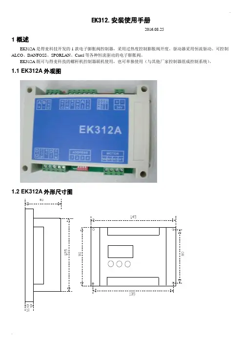
.EK312.安装使用手册-----2016.08.251 概述EK312A是得麦科技开发的1款电子膨胀阀控制器,采用过热度控制膨胀阀开度。
驱动器采用恒流驱动。
可控制ALCO、DANFOSS、SPORLAN、Carel等各种恒流驱动的电子膨胀阀。
EK312A既可与得麦科技的螺杆机控制器联机使用,也可单独使用(与其他厂家控制器组成控制系统)。
1.1 EK312A外观图1.2 EK312A外形尺寸图..1.3 EK312A 电气连接示意图EK312A电气连接示意图B-GA++-G TI DO W3W2W4AI +24G DI Com ComW1MotorB-GND A+ONOFF1234ON OFF1234O NO F FSW2JP2JP1JP3JP4JP5SW1VCCIout SW1地址1234OFF OFF 1ON OFF 2OFF ON 3ON ON4N LAC220VO N O FFSW212345V 10V举例1:12345123412312345612JP2-5设置为4-20mA输入O N O F FSW21234C V 5V 10V 举例2:JP2-5设置为0-10V输入O NO F FSW21234C V 5V 10V电子膨胀阀接线说明:ALCO膨胀阀:W4:白色W3:黑色W2:棕色W1:蓝色Danfoss膨胀阀:W4:黑色W3:白色W2:绿色W1:红色SPORLAN膨胀阀:W4:白色W3:黑色W2:绿色W1:红色Carel膨胀阀:W4:黄色W3:白色W2:棕色W1:绿色地址拔码说明:模拟输入拔码说明:报警输出启停开关电子膨胀阀24V电源输入压力传感器温度传感器通讯线运行故障通讯确认向上向下C V 0|10V0|5V 电压型电流型使用按键显示板备用注1:压力传感器接线:注2:压力传感器接线处,板内供电是24V ,如果传感器不是24V 供电,则要外接电源,之后将电源的负极接到板上的地(JP2-4)即可。

欧科水冷模块冷水机组EK325控制器使用手册EK325控制器使用手册1.简介1.1 概述1.2 功能特点1.3 技术参数2.安装与连接2.1 控制器安装2.2 连接电源2.3 连接传感器2.4 连接通信接口3.控制器界面3.1 主界面3.2 操作菜单3.2.1 设备信息3.2.2 参数设置3.2.3 系统运行状态 3.2.4 历史数据查询 3.2.5 报警信息3.2.6 系统维护3.3 参数设置3.3.1 温度设定3.3.2 定时设置3.3.3 通信设置4.系统运行状态监测4.1 温度监测4.2 压力监测4.3 液位监测4.4 流量监测4.5 故障诊断5.历史数据查询5.1 温度记录5.2 压力记录5.3 液位记录5.4 流量记录6.报警信息6.1 报警类型6.2 报警记录7.系统维护7.1 参数备份与恢复7.2 系统重启与恢复出厂设置7.3 固件升级附件:1.EK325控制器安装图纸2.电源连接图3.传感器连接图4.通信接口连接示意图法律名词及注释:1.本文档涉及的法律名词及注释如下:- 模块冷水机组:指包含冷却剂循环系统和控制系统的冷水机组设备,用于冷却工业设备或建筑物中的热源。
- 控制器:指用于控制和监测冷水机组运行状态的电子设备。
- EK325:指欧科水冷模块冷水机组的型号为EK325的控制器产品。
- 温度设定:指用户通过控制器设定的冷水机组的目标温度值。
- 历史数据查询:指用户通过控制器查询过去某一时间段内的温度、压力、液位和流量等数据。
- 报警信息:指控制器在发现设备异常或故障情况时,通过显示器或通信接口向用户发送的警告信息。
- 系统维护:指用户对控制器进行参数备份、系统重启、固件升级等操作以保证其正常运行和维护设备性能。
2.本文档仅用于EK325控制器的使用手册,不涉及其他产品或法律事项。
通用水冷模块机控制器安装使用手册程序编码: MD24 2015-12-14请务必仔细阅读此手册内容,并按照说明操作!如有疑问,请联系:广州得麦电子科技有限公司网址:邮箱:gzdaimc@(未经允许以任何形式或手段复制或传播本手册内容均属侵权,必究法律责任。
)目录一、安全使用 (3)二、产品简介 (4)2.1 SK系列真彩触摸屏显示器 (4)2.2 ZY101控制板性能指标 (4)三、安装指南 (5)3.1 4.3寸真彩触摸屏显示器SK043外型尺寸 (5)3.2 主控板ZY101外型尺寸 (5)四、主界面说明 (5)4.1开机界面 (6)4.2主界面 (6)4.3用户设置界面 (7)4.4输入查询界面 (7)4.5输出查询界面 (8)4.6故障查询界面 (9)4.7软件版本界面 (9)五、参数设置 (10)5.1厂家参数设置进入方式 (10)5.2维修参数设置进入方式 (11)5.3温度设置 (12)5.4时间设置 (12)5.5防冻设置 (13)5.6开关量定义 (13)5.7厂家参数 (14)5.8参数初始化 (14)5.9修改密码 (14)5.10维护时间设置 (15)六、控制逻辑 (17)6.1.1开机逻辑 (17)6.1.2关机逻辑 (17)6.1.3线控开关 (17)6.1.4冷却塔风机 (17)七、通讯接线示意图 (18)八、水冷模块机机电气连接示意图 (19)九、版本说明 (21)一、安全使用提示:危险!会引起人身伤亡和财产损失的不正确操作与安装。
警告!会引起人身伤害和财产损失的不正确操作与安装。
注意!会影响控制器性能的不正确操作。
二、产品简介水冷柜机控制器采用分体安装,由SK系列真彩触摸屏显示器和ZY101控制板两部分组成。
显示器采用400MHZ ARM9处理器,支持4.3寸,7寸、10寸不同大小真彩屏,可满足几乎所有工业现场应用需求。
ZY101控制板是专门为暖通或中央空调行业应用定制的。
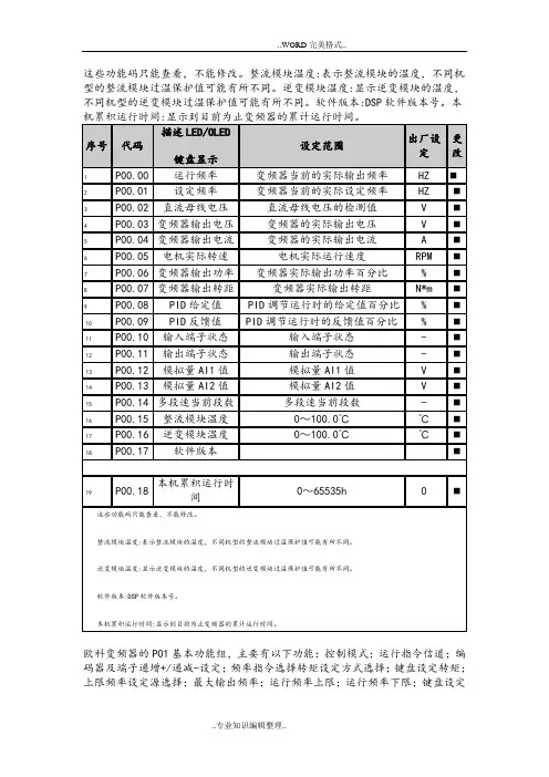
频率;加速时间1;减速时间1;运行方向选择;载波频率设定;功能参数恢复;AVR功能选择
欧科变频器的P01基本功能组,主要有以下功能:控制模式;运行指令信道;编码器及端子递增+/递减-设定;频率指令选择;转矩设定方式选择;键盘设定转矩;上限频率设定源选择;最大输出频率;运行频率上限;运行频率下限;键盘设定频率;加速时间1;减速时间1;运行方向选择;载波频率设定;功能参数恢复;AVR功能选择
P01组基本功能组
P02.00启动运行方式;P02.01 启动开始频率;P02.02启动频率保持时间;P02.03 启动前制动电流;P02.04 启动前制动时间;P02.05 停机方式选择;P02.06 停机制动开始频率;P02.07 停机制动等待时间;P02.08 停机直流制动电流;P02.09 停机直流制动时间;P02.10 正反转死区时间;P02.11 上电端子运行保护选择;P02.12 预留
欧科变频器P02启停控制组主要具有以下功能:P02.00启动运行方式;P02.01 启动开始频率;P02.02启动频率保持时间;P02.03 启动前制动电流;P02.04 启动前制动时间;P02.05 停机方式选择;P02.06 停机制动开始频率;P02.07 停机制动等待时间;P02.08 停机直流制动电流;P02.09 停机直流制动时间;P02.10 正反转死区时间;P02.11 上电端子运行保护选择;P02.12 预留
P02组启停控制组。

E K312A.操作手册.160825.1(总7页)本页仅作为文档封面,使用时可以删除This document is for reference only-rar21year.MarchEK312.安装使用手册-----2016.08.251概述EK312A是得麦科技开发的1款电子膨胀阀控制器,采用过热度控制膨胀阀开度。
驱动器采用恒流驱动。
可控制ALCO、DANFOSS、SPORLAN、Carel等各种恒流驱动的电子膨胀阀。
EK312A既可与得麦科技的螺杆机控制器联机使用,也可单独使用(与其他厂家控制器组成控制系统)。
1.1EK312A外观图1.2 EK312A外形尺寸图31.3 EK312A 电气连接示意图EK312A电气连接示意图B-GA++-G TI DO W3W2W4AI +24G DI Com ComW1MotorB-GND A+ONOFF1234ON OFF1234O NO F FSW2JP2JP1JP3JP4JP5SW1VCCIout SW1地址1234OFF OFF 1ON OFF 2OFF ON 3ON ON4N LAC220VO N O FFSW212345V 10V举例1:12345123412312345612JP2-5设置为4-20mA输入O N O F FSW21234C V 5V 10V 举例2:JP2-5设置为0-10V输入O N O F FSW21234C V 5V 10V电子膨胀阀接线说明:ALCO膨胀阀:W4:白色W3:黑色W2:棕色W1:蓝色Danfoss膨胀阀:W4:黑色W3:白色W2:绿色W1:红色SPORLAN膨胀阀:W4:白色W3:黑色W2:绿色W1:红色Carel膨胀阀:W4:黄色W3:白色W2:棕色W1:绿色地址拔码说明:模拟输入拔码说明:报警输出启停开关电子膨胀阀24V电源输入压力传感器温度传感器通讯线运行故障通讯确认向上向下C V 0|10V0|5V 电压型电流型使用按键显示板备用注1:压力传感器接线:注2:压力传感器接线处,板内供电是24V ,如果传感器不是24V 供电,则要外接电源,之后将电源的负极接到板上的地(JP2-4)即可。
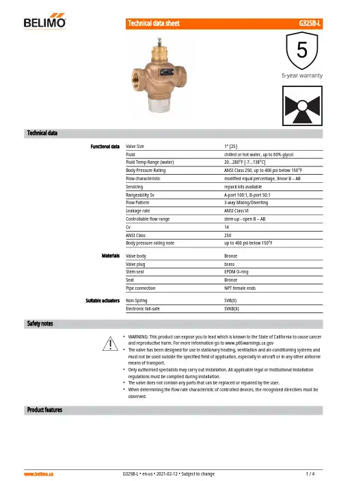
G325B-L•••••Technical dataFunctional dataValve Size 1" [25]Fluidchilled or hot water, up to 60% glycol Fluid Temp Range (water)20...280°F [-7...138°C]Body Pressure Rating ANSI Class 250, up to 400 psi below 150°F Flow characteristic modified equal percentage, linear B – AB Servicing repack kits available Rangeability Sv A-port 100:1, B-port 50:1Flow Pattern 3-way Mixing/Diverting Leakage rateANSI Class VI Controllable flow range stem up - open B – AB Cv 14 ANSI Class250Body pressure rating noteup to 400 psi below 150°F MaterialsValve body Bronze Valve plug brass Stem seal EPDM O-ring SeatBronze Pipe connectionNPT female ends Suitable actuatorsNon-Spring SVB(X)Electronic fail-safeSVKB(X)Safety notesWARNING: This product can expose you to lead which is known to the State of California to cause cancer and reproductive harm. For more information go to The valve has been designed for use in stationary heating, ventilation and air-conditioning systems and must not be used outside the specified field of application, especially in aircraft or in any other airborne means of transport.Only authorised specialists may carry out installation. All applicable legal or institutional installation regulations must be complied during installation.The valve does not contain any parts that can be replaced or repaired by the user.When determining the flow rate characteristic of controlled devices, the recognised directives must be observed.Product featuresG325B-L Flow/Mounting detailsDimensionsDimensional drawingsNFA B C D E F10.2" [260] 4.4" [112]12.8" [325]10.2" [260] 1.2" [30] 4.9" [125]SVA B C D E F9.1" [231] 4.4" [112]10.3" [262]8.6" [218] 1.9" [48] 1.9" [48]SVKA B C D E F10.2" [260] 4.4" [112]11.0" [279]8.2" [208] 1.9" [48] 1.9" [48]SVKA B C D E F10.2" [260] 4.4" [112]11.0" [279]8.2" [208] 1.9" [48] 1.9" [48]NFX24-MFT-X1 Modulating, Spring Return, 24 V, Multi-FunctionTechnology®Technical dataElectrical data Nominal voltage AC/DC 24 VNominal voltage frequency50/60 HzPower consumption in operation 6.5 WPower consumption in rest position 3 WTransformer sizing9 VA (class 2 power source)Electrical Connection18 GA appliance cable, 3ft [1m] 10ft [3m] and 16ft[5m], with 1/2" conduit connector, degree ofprotection NEMA 2 / IP54Overload Protection electronic throughout 0...95° rotationFunctional data Operating range Y 2...10 VOperating range Y note 4...20 mA w/ ZG-R01 (500 Ω, 1/4 W resistor)Operating range Y variable Start point 0.5...30 VEnd point 2.5...32 VOptions positioning signal variable (VDC, PWM, on/off, floating point)Position feedback U 2...10 VPosition feedback U note Max. 0.5 mAPosition feedback U variable VDC variableDirection of motion motor selectable with switch 0/1Direction of motion fail-safe reversible with cw/ccw mountingManual override 5 mm hex crank (3/16" Allen), suppliedAngle of rotation95°, adjustable with mechanical end stop, 35...95°Angle of rotation note adjustable with mechanical end stop, 35...95°Running Time (Motor)default 150 s, variable 40...150 s, constant,independent of loadRunning time motor note constant, independent of loadRunning time motor variable40...150 sRunning time fail-safe<20 s @ -4...122°F [-20...50°C], <60 s @ -22°F [-30°C]Override control MIN (minimum position) = 0%MID (intermediate position) = 50%MAX (maximum position) = 100%Noise level, motor50 dB(A)Noise level, fail-safe62 dB(A)Position indication MechanicalSafety data Degree of protection IEC/EN IP54Degree of protection NEMA/UL NEMA 2 UL Enclosure Type 2Agency Listing cULus acc. to UL60730-1A/-2-14, CAN/CSAE60730-1:02, CE acc. to 2014/30/EU and 2014/35/EU; Listed to UL 2043 - suitable for use in airplenums per Section 300.22(c) of the NEC andSection 602.2 of the IMCNFX24-MFT-X1•••••••Quality Standard ISO 9001Ambient temperature -22...122°F [-30...50°C]Storage temperature -40...176°F [-40...80°C]Ambient humidity max. 95% r.H., non-condensing Servicingmaintenance-free Weight Weight 4.4 lb [2.0 kg]MaterialsHousing materialGalvanized steel and plastic housingSafety notesPVC W'Shld for GV w/UGLK (AM)Classic GM to GMB(X) retrofit bracket.Battery Back Up System for SY(7~10)-110ZS-300 Mounting Bracket Set 120 to 24 VAC, 40 VA transformer.Cable for ZTH US to actuators w/o diagnostics socket.PC Tool computer programming interface, serial port.Electrical installationINSTALLATION NOTESActuators with appliance cables are numbered.Provide overload protection and disconnect as required.Actuators may also be powered by 24 VDC.Only connect common to negative (-) leg of control circuits.A 500 Ω resistor (ZG-R01) converts the 4...20 mA control signal to 2...10 V.Control signal may be pulsed from either the Hot (Source) or Common (Sink) 24 V line.For triac sink the Common connection from the actuator must be connected to the Hot connection of the controller. Position feedback cannot be used with a triac sink controller; the actuator internal commonreference is not compatible.Actuators may be connected in parallel if not mechanically linked. Power consumption and inputimpedance must be observed.IN4004 or IN4007 diode. (IN4007 supplied, Belimo part number 40155).Meets cULus requirements without the need of an electrical ground connection.Warning! Live Electrical Components!During installation, testing, servicing and troubleshooting of this product, it may be necessary to work with live electrical components. Have a qualified licensed electrician or other individual who has been properly trained in handling live electrical components perform these tasks. Failure to follow all electricalsafety precautions when exposed to live electrical components could result in death or serious injury.On/Off Floating PointNFX24-MFT-X1VDC/mA Control PWM ControlOverride Control。
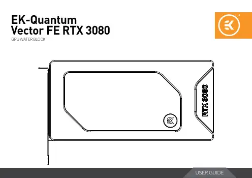
EK-Quantum Vector FE RTX 3080GPU WATER BLOCKBefore you start using this product, please follow these basic guidelines: Carefully read the manual before beginning with the installation process.Remove your graphics card from the computer for the safest mounting process to prevent any possible damage to your GPU or its circuit board (PCB).EK Fittings require only a small amount of force to screw them firmly in place since the liquid seal is ensured with the rubber O-ring gaskets.The use of quality market-proven corrosion-inhibiting coolants is always strongly recommended for any liquid cooling system.Do not use pure distilled water as a cooling liquid! For best results, EK recommends the use of EK-CryoFuel Coolants. Make sure to bleed air out of your water block thoroughly to reach optimal performance.TABLE OF CONTENTSBOX CONTENTS 4 WATER BLOCK DIMENSIONS 5 TECHNICAL SPECIFICATIONS AND MAIN WATER BLOCK PARTS 6 PREPARING THE GRAPHICS CARD 7 REMOVING THE STOCK COOLER 7 CLEANING THE PCB 7 CUTTING AND PLACING THERMAL PADS 8 APPLYING THERMAL COMPOUND 9 INSTALLING THE WATER BLOCK 9 REMOVING THE STOCK BACKPLATE 9 REMOVING THE STOCK BACKPLATE COVER 10 REMOVING THE PRE-INSTALLED I/0 SHIELD 10 PLACING THE BLOCK ON THE GRAPHICS CARD 11 ATTACHING THE BLOCK TO THE GRAPHICS CARD 11 ATTACHING THE I/O SHIELD 12 INSTALLING THE BACKPLATE 13 BACKPLATE DIMENSIONSBACKPLATE COVER DIMENSIONSREQUIRED TOOLS 14 CUTTING AND PLACING THERMAL PADS 14 ATTACHING THE BACKPLATE 15 REPLACING THE TERMINAL (Optional Step) 16 CHECKING FOR CONTACT 17 INSERTING THE GRAPHICS CARD INTO THE CHASSIS 18 INSTALLATION OF FITTINGS AND TUBING 18 CONNECTING THE D-RGB LED STRIP 19 TESTING THE LOOP 19 SUPPORT AND SERVICE 20 SOCIAL MEDIA 20WATER BLOCK DIMENSIONSTECHNICAL SPECIFICATIONS AND MAIN WATER BLOCK PARTSTechnical Specification: Array - Dimensions (LxHxW): 206 x 100 x 29 mm- D-RGB (Addressable RGB) Cable - Length: 500 mm- D-RGB LED Count: 20- D-RGB Connector: Standard 3-Pin (+5V, Data, Blocked, Ground)PREPARING THE GRAPHICS CARDSTEP 1REMOVING THE STOCK COOLERPlace your graphics card on the flat surface and carefully remove thestock cooler. Do not forget to unplug all the LED and fan connectors.Pay attention to the following steps when installing the EK-QuantumVector FE RTX 3080 water block onto your graphics card.STEP 1Your GPU water block comes with thermal pads that have to be cut into smaller pieces to cover all the VRM components, such as COILs, MOSFETs, and drivers.Replacement thermal pads:10x Thermal Pad F 1.0mm – (120 x 16 mm) EAN: 3830046996732CUTTING AND PLACING THERMAL PADSSTEP 2Once cut to size, thermal pads should be placed on the PCB, as illustrated below. EK made sure to provide you with more than an adequate quantity of thermal pads to complete this Step.STEP 1Apply the enclosed EK -TIM Ectotherm thermal grease (thermal compound) on the CPU heat spreader – IHS – as shown in the image. The layer of the thermal compound must be thin and even over the entire surface of the IHS.APPLYING THERMAL COMPOUNDFor this Step, you will need: For this Step, you will need: INSTALLING THE WATER BLOCKSTEP 1REMOVING THE STOCK BACKPLATECarefully unscrew four (4) preinstalled backplate screws (M2.5 X 7 AX1) and remove the backplate, as shown in the picture. Save the screws and backplate for later use.STEP 3REMOVING THE PRE-INSTALLED I/0 SHIELDUnscrew the three (3) M3X5 screws using Phillips head-screwdriver and remove the I/O shield (as shown in the picture). Save the screws and I/O shield for the later use! For this Step, you will need:For this Step, you will need: STEP 2REMOVING THE STOCK BACKPLATE COVERAfter removing the backplate, unscrew the three (3) backplate cover screws as shown in the picture, using the enclosed Allen Key (2 mm), and take off the backplate cover. Save the screws and cover for later use.PLACING THE BLOCK ON THE GRAPHICS CARDThis procedure is the same for all full-cover water blocks.Carefully position the water block with preinstalled standoffs on the graphics card. During this process, make sure you have aligned mounting holes of the PCB with holes of the water block (the same applies to other tops).For this Step, you will need:STEP 5ATTACHING THE BLOCK TO THE GRAPHICS CARDUse four (4) M2.5 X 4 AX1 screws and M2.5 PVC washers, as shown in the image. Tighten the screws around the GPU core evenly using the Phillips head screwdriver. Always use a plastic washer under each screw!For this Step, you will need:ATTACHING THE I/O SHIELDTake the stored screws and I/O shield after attaching the water block. Attach them on to the water block as shown in the picture. Do not use excessive force.INSTALLING THE BACKPLATEBACKPLATE DIMENSIONS BACKPLATE COVER DIMENSIONSREQUIRED TOOLSYour backplate comes with thermal pads that have to be cut into smaller pieces to cover all the VRM components. EK made sure to provide you with more than an adequate quantity of thermal pads to complete this Step.CUTTING AND PLACING THERMAL PADSOnce cut to size, thermal pads should be placed on the backplate, as shown in the image.ATTACHING THE BACKPLATESTEP 2After securing the backplate, place the backplate cover on the PCB and make sure all holes are aligned. Position an M3 X 12 DIN7991 screw in each of the three (3) mounting holes (as shown in the image) and tighten them evenly with a Allen Key 2mm. Do not use excessive force!For this Step, you will need:STEP 1Place the backplate on the PCB and make sure all holes are aligned. Position an M2.5 x 7 AX1 screw in each of the three (4) mounting holes (as shown in the image) and tighten them evenly with a Phillips Head Screwdriver.For this Step, you will need:REPLACING THE TERMINAL (Optional Step)With the EK-Quantum Vector FE RTX 3080 water block, you also get an additional terminal. Follow these steps to install it.STEP 1Unscrew three (3) M4X24.5 DIN7984 terminal screws with the enclosed 2.5mm Allen K ey. Remove the stock terminal. Save the screws and terminal O-Rings for later.For this Step, you will need:STEP 2Before you attach the new terminal, make sure that terminal gasketsare placed inside holes on the coldplate (as shown in the picture). For this Step, you will need:For this Step, you will need:STEP 3Carefully place the terminal on the coldplate and secure it with previously saved M4 X 24.5 DIN7984 screws. Do not use excessive force when tightening the screws. CHECKING FOR CONTACTIf necessary, temporarily remove the water block to check for uniform surface contact between the block and components. Pay special attention to the VRM section of the graphics card. Check whether the water block makes contact with the intended integrated circuit. Then repeat Steps from the previous section to re-attach the block.INSERTING THE GRAPHICS CARD INTO THE CHASSISCarefully lift your graphics card with the installed water block and insert it into your PC’s motherboard PCIexpress expansion slot. Please bear in mind that your graphics card is very likely heavier than before it was equipped with the water block.INSTALLATION OF FITTINGS AND TUBINGSTEP 1Screw-in two (2) G1/4 threaded male fittings. Attach the liquid cooling tubes and connect the water block(s) to the cooling loop.You can use any opening as an inlet/outlet port.EK recommends using EK fittings with all EK water blocks.To make sure the installation of EK components was successful, we recommend you perform a 24-hour leak test.When your loop is complete and filled with coolant, connect the pump to a PSU outside of your system. Do not connect power to any of the other components. Turn on the PSU and let the pump run continuously.Inspect all parts of the loop, and in case the coolant leaks, fix the issue and repeat the testing process. To prevent possible damage, please ensure that all hardware is dry before the system is powered on.SUPPORT AND SERVICE In case you need assistance, please contact: https:///customer-support/ EKWB d.o.o.Pod lipami 181218 KomendaSlovenia - EUSOCIAL MEDIAEKWaterBlocks@EKWaterBlocksekwaterblocksEKWBofficialekwaterblocks。

INSTALLATION MANUAL EKMV2C09B7EKMV3C09B7Installation manual 1EKMV2C09B7 + EKMV3C09B72-way valve kit/3-way valve kit for fan coil units4PW65144-1 – 10.2010The English text is the original instruction. Other languages are translations of the original instruction.This option kit needs to be used in combination with an EKRP1C11kit and a FWF or FWC fan coil unit.The units are equipped with a water inlet and water outlet for connection to a water circuit. This circuit must be provided by a licensed technician and must comply with all relevant European and national regulations.A CCESSORIES SUPPLIED WITH THE KITC ONNECTION OF THE FAN COIL UNIT TO FIELD PIPING BY USE OF THE 2-WAY /3-WAY VALVERefer to the installation manual of the fan coil unit for details on installing the fan coil unit.If air, moisture or dust gets in the water circuit, problems may occur.Therefore, always take into account the following when connecting the water circuit:■Use clean pipes only.■Hold the pipe end downwards when removing burrs.■Cover the pipe end when inserting it through a wall so that no dust and dirt enter.■Use a good thread sealant for the sealing of the connections.The sealing must be able to withstand the pressures and temperatures of the system.■When using non-brass metallic piping, make sure to insulate both materials from each other to prevent galvanic corrosion.■Because brass is a soft material, use appropriate tooling for connecting the water circuit. Inappropriate tooling will cause damage to the pipes.EKMV2C09B7EKMV3C09B72-way valve kit/3-way valve kit for fan coil unitsInstallation manualRead this manual attentively before installation. Do not throw it away. Keep it in your files for future reference.Improper installation or attachment of equipment or accessories could result in electric shock, short-circuit,leaks, fire or other damage to the equipment. Be sure only to use accessories made by Daikin that are specifically designed for the use with the equipment and have them installed by a professional.If unsure of installation procedures or use, always contactyour dealer for advice and information.Danger: electric shockSwitch off all power supply before removing the control box cover or before making any connections or touching electrical parts.1Actuator with toothed ring22-way valve (only for EKMV2C09B7)33-way valve (only for EKMV3C09B7)4Insulation tape 5Insulation for valve 6Installation manual7O-ring (1x for EKMV2C09B7) (2x for EKMV3C09B7)8Wire (in case 2 valves are connected on same fan coil unit)■KRP1H98 box and EKRP1C11 PCB are needed for combination with the FWC units.piping can cause malfunction of the unit.excessive corrosion of the water piping.■Never use Zn-coated parts in the water circuit.Excessive corrosion of these parts may occur as copper piping is used in the unit's internal water circuit.■The equipment is not intended for use in a potentially explosive atmosphere.EKMV2C09B7 + EKMV3C09B72-way valve kit/3-way valve kit for fan coil units4PW65144-1 – 10.2010Installation manual2Water piping connections2 pipe modelsFWFFWC4 pipe modelsFWFFWC1Mount the actuator on the valve body.1Remove the blue and red cap from the valve.2Push the toothed ring firmly onto the valve.3Mount the actuator on the ring.4Rotate the actuator 15° clockwise until you hear a "click". In order to unfasten the actuator, rotate it 15° counterclockwise.5Push the red button inwards.2-way valve3-way valveM odify the inlet side (A) so that the distance between the connection points is equal to 50 mm.1Water out 2Water in 3Air purge1Water out heating coil 2Water in heating coil 3Water out cooling coil 4Water in cooling coil 5Air purge heating coil 6Air purge cooling coil3121234561563422354234A50 mm5Installation manual 3EKMV2C09B7 + EKMV3C09B72-way valve kit/3-way valve kit for fan coil units4PW65144-1 – 10.20102Mount the valve on the water piping.1Install the o-ring in the water piping connection. In case of a 3-way valve, install the second o-ring in the second water piping.2Install the valve on the inlet water piping 2-way valve3-way valve3Connect the field piping.The complete water circuit, inclusive all piping, must be insulated to prevent condensation and reduction of the capacity (minimum thickness: 10 mm).If the temperature is higher than 30° and the relative humidity is higher than 80%, the thickness of the sealing materials should be at least 20 mm in order to avoid condensation on the surface of the sealing.4Seal the valve and piping connections.1Add the "insulation for valve" (1) around the valve and the sealing of the unit piping and the field piping.2Close the sealing off with the insulation tape (2).Example: 3-way valveThe arrow must point inside the inlet water piping of the fan coil unit.Make sure the actuator is not installed upside down.Pay attention to the mark on the 3-way valvebody.The long arrow must point inside the inlet water piping of the fan coil unit.In case 2 valves are installed on the same fan coil unit (4 pipe model), use the same method described above to install the second valve.1212Required thread type on the field piping sideNo valves installed 2-way valve(s)installed 3-wayvalve(s) installed2 pipeunitWater in 3/4" male BSP 3/4" female BSP 3/4" femaleBSPWater out 3/4" male BSP 3/4" male BSP 3/4" femaleBSP4 pipe unitWater in Heating 3/4" male BSP 3/4" female BSP 3/4" female BSP Water out Heating 3/4" male BSP 3/4" male BSP 3/4" female BSP Water in Cooling 3/4" male BSP 3/4" female BSP 3/4" female BSP Water out cooling 3/4" male BSP 3/4" male BSP 3/4" female BSPinformation.1Insulation for valve 2Insulation tape122EKMV2C09B7 + EKMV3C09B72-way valve kit/3-way valve kit for fan coil units4PW65144-1 – 10.2010Installation manual4Electrical connectionsFor the FWF 1Install the KRP1B101 box and the EKRP1C11 PCB according to the installation manual provided with the KRP1B101 kit.For wiring of the EKRP1C11 PCB: see below.For the FWC 1Install the KRP1H98 box and the EKRP1C11 PCB according to the installation manual provided with the KRP1H98 kit.For wiring of the EKRP1C11 PCB: see below.2Wiring of the EKRP1C11■Power supply■Communication wireDo not drill any holes in the casing of the unit to install the option.Only use the accessories provided by Daikin to install the option.EKRP1C11 can not be used.1Communication to fan coil PCB 2Power supply wire (to fan coil unit)3Fuses 5 A - 250 V4YC-Y1: connection of first valve5X1-Y4: wire to enable the use of the second valve (supplied with valve kit)6X2-Y2: connection of second valveInstallation manual 5EKMV2C09B7 + EKMV3C09B72-way valve kit/3-way valve kit for fan coil units4PW65144-1 – 10.2010■Wiring method FWFFWCNever squeeze bundled cables and be sure that the cables do not come in contact with sharp edges.Cut off the redundant ends of the tie wraps.■In case 2 valves are used:Strip the wire of the valve motor of the second actuator for an additional length of 50 mm.Connect X1 and Y4 with the wire supplied with the kit (see "Accessories supplied with the kit", item 8).1Communication wire 2Power supply wire 3First valve wire 4Second valve wire 5Tie wrap552134543211X1-Y4 wire2X2-Y2: connection of the second valve12NOTES4PW65144-1 10.2010C o p y r i g h t 2010D a i k i n。
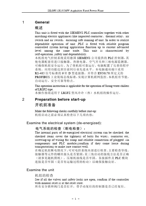
1 General概述This unit is fitted with the SIEMENS PLC controller together with othermatching electric appliances like imported contactor、thermal relay、airswitch and air switch,ensuring safe running of unit. In order to realizedependable operation of unit ,PLC is fitted with reliable programcontrolled system having application function up to current advancedlevel among the same trade. This unit is characterized byself-operation ,safety and dependability.本机组电气控制系统采用德国SIEMENS公司提供的PLC控制器,其他电器配套有进口接触器、热继电器、空气开关和三相电源监测器,可确保机组安全运行。
为了使机组可靠运行,电脑配置了完善的程序系统,应用功能达到目前同行业先进水平。
本电脑通讯端口采用RS-485信号标准的9针D型连接器,并符合EN50170所定义的PROFIBUS工业现场总线标准,实现计算机联网监控。
本机组有节能,自动运行,安全可靠等特点。
This operation instruction is applicable for the operation of Jirong water chillersof LRSFZ type.本操作指南适用于LRSFZ型风冷冷(热)水机组的操作运行。
2 Preparation before start-up开机前准备Make the following checks carefully before start-up:机组启动之前必须认真检查以下几项内容:Examine the electrical system (de-energized):电气系统的检查(断电检查):The internal parts of de-energized electrical system can be checked. thechecked items cover the tightness of bolts for wires、contactor etc,screwing-up of wiring for comp and reliable connection of plugged –incomponents and PLC module,(confirm if they come loose duringtransportation) to make sure contact well.在确定机组断电情况下,可对电控系统内部进行检查。
关注未来,期待成为您的战略合作伙伴Focus On Future,We expect to be your strategic supplier讴科冷库使用手册冷冻/冷藏库使用说明及注意事项一、冷库安装前的准备工作•冷库设备安放在通风良好的干燥洁净环境中。
禁止在易燃、易爆、易腐蚀、有破坏绝缘的气体和导电尘埃的环境中使用本设备,禁止在不安全或有安全隐患的环境中使用本设备。
冷库安装之前,三相四线电源一定要到位。
•应有足够的空间进行冷库设备的安装,地面用混凝土抹面找平,一定要保证地面水平,以确保冷库拼装的整体效果。
地面耐力不小于3T/m2。
•冷库使用的电源为三相四线380V/50Hz(±10%),检查使用的电源是否与设备配套。
线载负荷是否符合要求而满足设备的的正常运行。
并配备冷库专用保护电闸。
•冷库设备一般配用风冷式冷凝器,不需要用水,特别适用于边远地区和缺水地区使用。
(有些情况下用户要求用水冷式冷凝器,此时用户要配置水池或水井)•冷库设备应有专人负责看管。
并了解用电常识和熟悉冷库的基本构造、性能。
二:冷库设备的安装先检查设备的外包装是否破损。
拆箱后对照装箱单检查所有随机文件和配件是否齐全。
检查机器的零部件是否因长途运输、搬运而松动、破损。
用户根据厂方提供的图纸和安装说明书进行安装调试。
当用户对冷库的常识不甚了解或对冷库安装毫无把握时,可与厂方达成协议,由厂方为您提供有偿服务。
三:冷库设备的使用常识和注意事项•冷库内放置的物品应留有一定空隙,利于冷气的流动。
库底板上要加木格保护层。
•冷库的制冷机组周围严禁堆放物体并远离发热源,以利于空气流动而充分散热,并定期用软毛刷清除制冷机组、散热器上的灰埃。
这些都是为了确保散热。
•冷库的库温设定应在规定的范围内,否则会增加冷库的工作负荷而损坏冷库元件。
储藏保鲜库库内温度设定在0~+5℃,冷冻库库内温度一般设定在0~-15℃,低温库库内温度一般设定在-10~-20℃。
This product is intended for installation only by expert users. Please consult with a qualified technician for installation. Improper installation may result in damage to your equipment. EK Water Blocks assumes no liability whatsoever, expressed or implied, for the use of these products, nor their installation. The following instructions are subject to change without notice. Please visit our web site atBefore installation of this product please read important notice, disclosure and warranty conditions printed on the back of the box or our home page.The barb hose fittings require only a small amount of force to screw them in; otherwise the high flow fittings might break. These fittings do not need to be tightened with much force because the liquid seal is made using o-rings. The use of an algaecide and corrosion inhibitors is always recommended for any liquid cooling system.Remove all 8 screws holding the original heat-pipe cooler / backplate assembly to the motherboard’s circuit board.2. CLEANING THE PCB. Carefully detach the original stock cooler after removing screws securing it to the board. Wipe off the remains (by using nonas shown on sample photo) of the original thermal compound until the components and circuit board are completely clean. EKWB does not recommend using any liquids for removing paste.3. APPLYING THERMAL COMPOUNDApply thermal compound: lightly coat the NF200 (NB) and P67 PCH (SB chips with for example Arctic Cooling MX-2 ™ or MX-4 ™ thermal grease. EKWB recommends to apply thermal grease in cross form for best performance (see sample picture). 4. CUTTING THERMAL PADS. Two (2) 90x15x1mm thermal pads are enclosed with your EK-FB Max4 Extreme water block. You will have to cut the thermal pad in order to cover all marked surfaces surface. (WARNING: DIMENSIONS ON PICTURES BELLOW ARE SCALED!)5. PLACING THERMAL PADS ON MOTHERBOARD. Place thermal pads you cut on PCB as shown on picture bellow. BOTH SIDES PRIOR TO INSTALLATION.)STEP 4: ATTACHING BLOCK TO MOTHERBOARDMOUNTING THE BLOCK. perfect thermal contact, the block does not use a spring mounting system; therefore when attaching be very careful to tighten all screws equally. Tightening the screws beginning in the center of the block near the northbridge, and continue evenly outwards. Do not use too much pressure onbend and either cause bad contact with water block, or break a connection on the circuit board.STEP 5: CHECKING FOR CONTACTSemove the water block to check for uniform surface contact between the block and the components. Note the pattern of contact on a piece of paper. Then repeat steps 3 and 4 to reattach the block. Block was tested on physical hardware. Due to height variations of chipset some differences may occur. In case you have problem with block contacts please write to our support mail.port.scissors philips screwdriver EK-PSC compression fittingTwo 3,3mmstandoffs combinedon the SB part ofthe waterblock2,1mm standoffsUse two (2) enclosed M3x12 DIN7985screws on the southbridge part of theM2.5x6 DIN7985screwphilips head screwdriver。
EK312.安装使用手册1概述EK312A是得麦科技开发的1款电子膨胀阀控制器,采用过热度控制膨胀阀开度。
驱动器采用恒流驱动。
可控制ALCO、DANFOSS、SPORLAN、Carel等各种恒流驱动的电子膨胀阀。
EK312A既可与得麦科技的螺杆机控制器联机使用,也可单独使用(与其他厂家控制器组成控制系统)。
1.1EK312A外观图1.2EK312A外形尺寸图21.3 EK312A 电气连接示意图EK312A电气连接示意图B-GA++-G TI DO W3W2W4AI +24G DI Com ComW1MotorB-GND A+ONOFF1234ON OFF1234O NO F FSW2JP2JP1JP3JP4JP5SW1VCCIout SW1地址1234OFF OFF 1ON OFF 2OFF ON 3ON ON4N LAC220VO N O F FSW212345V 10V举例1:12345123412312345612JP2-5设置为4-20mA输入O N O F FSW21234C V 5V 10V 举例2:JP2-5设置为0-10V输入O N O F FSW21234C V 5V 10V电子膨胀阀接线说明:ALCO膨胀阀:W4:白色W3:黑色W2:棕色W1:蓝色Danfoss膨胀阀:W4:黑色W3:白色W2:绿色W1:红色SPORLAN膨胀阀:W4:白色W3:黑色W2:绿色W1:红色Carel膨胀阀:W4:黄色W3:白色W2:棕色W1:绿色地址拔码说明:模拟输入拔码说明:报警输出启停开关电子膨胀阀24V电源输入压力传感器温度传感器通讯线运行故障通讯确认向上向下C V 0|10V0|5V 电压型电流型使用按键显示板备用注1:压力传感器接线:注2:压力传感器接线处,板内供电是24V ,如果传感器不是24V 供电,则要外接电源,之后将电源的负极接到板上的地(JP2-4)即可。
2控制逻辑EK312A可选择“吸气过热度”、“手动”、“模拟量控制”3种控制方式(由参数“P33膨胀阀控制方式”设置,默认吸气过热度控制)。