限流止回阀说明书
- 格式:doc
- 大小:147.00 KB
- 文档页数:3
1.范围本说明书包括了公称通径DN15mm~600mm(1/2”~24”)、公称压力PN1.6MPa~16MPa(ANSI CLASS150~900)螺纹端、法兰端、对焊端和承插焊端连接的旋启式、升降式止回阀。
2.用途2.1本阀用于管道或装置中,防止介质倒流。
2.2根据介质选用阀门的材质。
2.2.1碳钢阀门适用于水、蒸汽、油品等介质。
2.2.2不锈钢阀门适用于腐蚀性介质。
2.3适用温度:2.3.1普通碳钢阀门适用温度为-29℃~+425℃2.3.2合金钢阀门适用温度≤550℃2.3.3不锈钢阀门适用温度为-196℃~+200℃3.结构3.1止回阀基本结构见图13.2易损件垫片采用聚四氟乙烯或柔性石墨,密封可靠。
4.工作原理止回阀依靠介质本身的流动而自动开、闭阀瓣,防止介质倒流。
5.保管、保养、安装和使用5.1阀门应存放在干燥,通风的室内,阀门通道两端应堵塞。
5.2长期存放的阀门应定期检查,清除污物。
应特别注意密封面的清洁,防密封面的损坏。
5.3安装前应仔细核对阀门标志是否与使用要求相符。
5.4安装前应检查阀门内腔和密封面,如有污垢,应使用清洁布擦拭干净。
5.5安装前应注意阀门上流向标记与介质流动方向一致。
5.6。
升降式垂直瓣止回阀应安装在垂直管道上,升降式水平瓣止回阀和旋启式止回阀应安装在水平管道上。
5.7使用中应注意阀门是否有异常声音和振动,为防止在管路中产生水锤效应,应注意管路介质压力波动情况。
6.可能发生的故障、原因及消除方法见表1-1-7.保修制造厂对阀门投入使用一年内负责保修,但不超过发货期18个月。
在保修期内,因产品质量原因均可免费修理或更换零件。
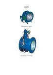
a.法兰连接旋启式止回阀b.法兰连接升降式止回阀-2-。
止回阀操作说明书止回阀也称作逆止阀或单向阀,用来防止管路中的介质倒流。
它属于自动阀门,其启闭动作是依靠管路内介质本身的能量来驱动的,无需外力。
一、技术参数压力等级1500Lb规格6"工作温度-29℃~425℃适用介质水、油品三、结构和主要材料1.结构止回阀主要由阀体、阀盖、阀瓣、摇臂、阀座等组成,见旋启式止回阀结构示意图。
止回阀分成升降式和旋启式两大类,API 6D中仅包括旋启式止回阀,其关闭件是阀瓣,它有一个、两上或多个,分别称作单瓣旋启式止回阀、双瓣旋启式止回阀和多瓣旋启式止回阀。
阀瓣呈圆盘(或半圆盘)状,它通过摇臂可绕位于阀内通道上方的销轴旋转而启闭。
按其连接方式,止回阀分成对夹式和法兰连接两种,对夹式又有单瓣对夹式和双瓣对夹式之分。
本阀门属单瓣旋启式止回阀,法兰连接。
2.主要材料四、特点1.旋启式止回阀流体阻力较小2.阀内通道介质流动方向受到限制3.低压状态下,密封性能受到影响五、选用与安装1选用主要考虑使用工况和操作要求:止回阀的品种和规格很多,应按使用工况(如工作介质,操作压力,操作温度,管路通径等)以及安装操作要求(如连接方式)来选用适当的止回阀。
1.1 材料选用:A105、WCB主要适用于非腐蚀性介质。
如油、气、水等。
304、CF8主要适用于硝酸类介质。
316、CF8M主要适用于醋酸类介质。
1.2 根据温度选用ASME B16.34规定了ASTM各种材料的压力温度等级,该标准详细地规定了各种压力等级,不同壳体材料在各种操作温度下的最大工作压力(表压),它是设计和选用阀门的主要基准之一。
因而,选用止回阀时必须由操作压力和操作温度按压力温度等级(ASME B16.34)来确定所选用止回阀的材料(指壳体)和压力等级(指公称压力)。
如果操作温度、压力超负荷运行,可能导致阀门损坏。
选用阀门时应充分考虑各种工况条件,避免阀门超负荷运行。
1.3 操作温度过高或过低时,为防止烫伤或冻伤操作人员和温度损失,应在壳体上加保温层。
国家特种设备制造许可证号:TS2710604-2015
轴流式止回阀
安装使用说明书
中国•四川乐山市热工仪表有限公司
一、产品介绍:
轴流式止回阀是一个全新概念的系列。
该产品是根据差流可调阀的基本原理设计而成的。
轴流式止回阀内部流道采用流线型设计并设有导流体。
主要用于水泵出口或其他防止液体倒流的地方,可有效防止普通止回阀液体倒流时产生的水锤冲击和噪音,静音关闭并且密封性能好,是止回阀更新换代的产品。
二、主要性能特点:
1、采用双重密封结构。
无论阀后压力高低,阀门都关闭严密、密封性能好,克服了一般止回阀在中、低压情况下密封性能差的缺点。
2、较小流速下,阀门就可全开,而且还可以选择不同的阻抗以满足各种情况的要求。
一般情况下,阀门启闭迅速,如果用户需要,也可以设计成缓闭结构的止回阀,以满足其装置的需要。
3、采用流线型流道和导流体结构,阀门流阻小。
4、弹簧均按I类弹簧设计,采用不锈钢制造。
三、安装与使用说明:
1、阀门不受安装位置的限制,可以水平,也可以垂直安装。
2、安装前要彻底清除管道内的垃圾、杂物,以防止使用时垃圾卡住阀座与阀瓣,导致不止回,或损坏阀座与阀瓣,阀前请安装过滤器。
3、安装时要注意阀体外水流标示箭头,要遵循安装方向。
4、阀门长期不用时,或水流不动时,请注意防冻,并把阀内的水放净。
注:试验与检验按JB/T9092-1999标准
五、简图:。
盐城市圣泰阀门有限公司技术性文件
更改记录
STF-JS018—2003止回阀使用说明书 1/1
止回阀使用说明书
1、用途和性能规范:
本阀门系API 6D常规型止回阀,适用于温度为-20℉~ 800℉的水、蒸汽、油品其它非腐蚀介质的长输管线上,用来截断或接通介质流体介质。
其性能规范如下:
2、工作原理和结构说明
1)本阀门系常规旋启式止回阀,装置在水平管线上,依靠介质本身的流动而自动开闭阀瓣,用于防止介质倒流。
2)本阀门结构长度按API 6D规定,端法兰按ASME B16.5规定。
3)主体材料是WCB,中头垫片使用08F的软铁垫片。
4)本阀门的基本结构按照API600常规型楔式闸阀规定。
5)本阀门公称通径:8"。
三合一止回阀说明书一、简介、三合一止回阀安装在一般建筑,公寓及工厂的供排水,冷暖水处理,及锅炉的冷凝水,二次供水管道的泵出口上,用来防止泵停止运转而引起的管道内的介质倒流。
多功能三合一止回阀,是水泵出口上推荐使用的阀门,当水泵停止工作时,可以快速止回,这样就可以防止水锤产生.当泵初始运行时,阀瓣在凭借水底推力打开,阀门开启,同时弹簧在弹簧力的凭借下快速的关闭了,随着水流越来越小,几乎停止时,阀瓣完全闭合三合一多功能止回阀.没有水回流倒流现象,这样因为水不回流不倒流,不产生能动,防止水锤现象.二、结构特点1、用一个阀门,可以圆满地完成三种功能:止回阀、截止阀、平衡阀。
2、泵停止运转时,弹簧力先合上阀瓣,因而防止倒流。
3、通过调节开度,可以调节泵的输出量。
4、密封垫用丁腈橡胶制作,因而根本不会泄漏,可以吸收冲力。
5、弹簧是用不锈钢制作,因而具有很强的耐蚀性。
6、可节约水量的设备材料和费用,缩小安装空间。
7、由于形状和结构高等成流线型,因而压降很小。
8、水平管道,垂直管道上均可安装。
三工作原理当水泵启动后,液体从进口进入,顶开阀瓣,流向出口.当水泵停止时,由于阀瓣上安装了快闭弹簧,在介质出现倒流之前,流速接近于零时迅速关闭,防止了水锤的产生,消除了噪音.调节阀杆开度,可改变流量的大小.关闭阀杆,可起到截止阀的作用.主要用于水泵出口或其它防止液体倒流的地方,可有效的防止普通止回阀液体倒流时产生的水锤冲击和噪音,是止回阀的更新换代产品.安装了加速关闭弹簧,利用快关原理防止水锤的产生,防止介质倒流,达到静音关闭.四、适用范围三合一止回阀安装在一般建筑,公寓及工厂的供排水,冷暖水处理,及锅炉的冷凝水,二次供水管道的泵出口上,用来防止泵停止运转而引起的管道内的介质倒流。
五、管道比较图六,外形尺寸三合一止回阀主要外形尺寸七,安装及维护1、安装时要注意阀体外水流标示(箭头)如果箭头模糊不清,可观察阀门通经两侧以低进高出的原则安装,遵循方向安装,垂直、水平均可.2、止回功能:本产品出厂前调节杆为关闭状态安装管道后应逆时针旋转手轮使阀杆上升到最大刻度位置.3、截止功能:顺时针旋紧手轮即可截断流量达到截止功能.4、节流平衡功能:调节阀杆在开度最大的情况下顺时针旋转手轮可使流量变小;反之变大.在变频泵的领域中此功能可以起到降低能耗之功效.。
USERS MANUALStop valve zGLO Fig. 201Edition: 07/2016 Date: 01.07.2016CONTENTS1. Product description2. Requirement for maintenance staff3. Transport and storage4. Function5. Application6. Assembly7. Maintenance8. Service and repair9. Reasons of operating disturbances and remedy 10. Valve service discountinuity 11.Warranty terms1. PRODUCT DESCRIPTION201figureends threaded form straightStop valves are manufactured at different executions, they are designed for shut off and open the flowStop valves are provided with casted marking according to requirements of PN-EN19 standard. The marking facilitates technical identification and contains:∙ diameter nominal DN (mm), ∙ pressure nominal PN (bar),∙ body and bonnet material marking,∙ arrow indicating medium flow direction, ∙ manufacturer marking, ∙ heat number,∙ CE marking, for valves subjected 2014/68/UE directive. CE marking starts from DN322. REQUIREMENTS FOR MAINTENANCE STAFFThe staff assigned to assembly, operating and maintenance tasks should be qualified to carry out such jobs. If during valve operation heat parts of the valve, for example handwheel, body or bonnet parts could cause burn, user is obliged to protect them against touch.3. TRANSPORT AND STORAGETransport and storage should be carried out at temperature from –200 to 650C, and valves should be protected against external forces influence and destruction of painting layer as well. The aim of painting layer is to protect the valves against rust during transport and storage. Valves should be kept at unpolluted rooms and they should be also protected against influence of atmospheric conditions. There should be applied drying agent or heating at damp rooms in order to prevent condensate formation. The valves should be transported in such a way to avoid handwheel and valve stem damage.4. FUNCTIONApplication range was mentioned at catalogue card. The kind of working medium makes some materials to be use or to be prohibited for use. Valves were designed for normal working conditions. In the case that working conditions exceed these requirements (for example for aggressive or abrasive medium) user should ask manufacturer before placing an order.When selecting the valve for specific medium,”List of Chemical Resistan ce ” can be helpful. It can be found at manufacturer website near catalogue cards.Working pressure should be adapted to maximum medium temperature according to the table as below.ZETKAMA Sp. z o.o. ul. 3 Maja 12PL 57-410 Ścinawka ŚredniaAcc. to EN 1092-2 Temperature [º C]Material PN -10 do 120 150 200EN-GJL250 16 16 bar 14,4 bar 12,8 barPlant designer is responsible for valve selection suitable for working conditions.5.APPLICATIONApplication range was mentioned at catalogue card.6.ASSEMBLYDuring the assembly of balancing valves following rules should be observed:-to evaluate before an assembly if the valves were not damaged during the transport or storage,-to make sure that applied valves are suitable for working conditions and medium used in the plant,-to take off dust caps if the valves are provided with them,-to protect the valves during welding jobs against splinters and used plastics against excessive temperature,-steam pipelines should be fitted in such a way to avoid condensate collection; in order to avoid water hammer steam trap should be applied.Pipeline where the valves are fitted should be conducted and assembled in such a way that the valve body is not subjected to bending moment and stretching forces.Bolted joints on the pipeline must not cause additional stress resulted from excessive tightening, and fastener materials must comply with working conditions of the plant,-during pipeline painting valve stem should be protected,-stop valves can be assembled in any position, however it is recommended to install the valve with handwheel upwards, -screw down and non-return valves (version with spring) can be assembled in any position, screw down and non-return valves (version without spring) should be assembled only on the horizontal pipelines with handwheel upwardsIt should be take note of medium flow direction, marked with an arrow on the body.-before plant startup, especially after repairs carried out, flash out the pipeline through entirely open valve, in order to avoid solid particles or welding splinters which may be harmful for sealing surfaces,-strainer ( wire mesh filter) installed before the valve increases certainty of its correct action.7.MAINTENANCEDuring maintenance following rules should be observed:-startup process – sudden changes of pressure and temperature should be avoided when starting the plant,- valve is closed by turning the handwheel clockwise when looking from above the handwheel (according to arrow direction marked on the handwheel),-valve is opened by turning the handwheel counter-clockwise,It is prohibited to use additional lever when turning the handwheel,-performance of fitted valves can be checked by multiple closing and opening,-if leakage on stem occurs for valves Fig.201 packing rings are pressed by tightening threaded gland nut screwed in the bonnet, the nut press the rings by gland,Tighten the nuts-in the case of necessity to replace packing rings, it should be done without overpressure inside the valve, when the valve is completely open. In this position inner space of the valve is entirely shut off,-in order to refill packing rings of valves can be refilled when gland nut is unscrewed.In order to assure safety performance, each valve (especially rarely used) should be surveyed on regular basis.Inspection frequency should be laid down by user, but not less than one time per month.8.SERVICE AND REPAIRAll service and repair jobs should be carried out by authorized staff using suitable tools and original spare parts. Before disassembly of complete valve from the pipeline or before service, the pipeline should be out of operation. During service and repair jobs it is necessary to decrease pressure to 0 bars , valve temperature to ambient temperature and to use personal health protectives in pursuance of existing threat. After valve disassembly it is necessary to replace flange connection gaskets between valve and pipelineEverytime when valve bonnet was disassembled sealing surface should be cleaned. During assembly it should be applied new gasket of the same type as previously used. Body-bonnet bolt connections should be tighten when the valve is at open position.The bolts should be tighten evenly and crosswise by torque wrench.Tightness test should be carried out with water pressure of 1,5 nominal pressure of the valve.9.REASONS OF OPERATING DISTURBANCES AND REMEDY-When seeking of valve malfunction reasons safety rules should be strictly obeyedFault Possible reason RemedyNo flow Valve closed Open the valveFlange dust caps were not removed Remove dust caps on the flangesPoor flow Valve is not open enough Open the valveDirty filter Clean or replace the screenClogged pipeline Check the pipelineControl difficulties Dry stem Grease the stemGland packing tighten too much Slightly slacken gland nuts. Put attention tokeep stuffing box tightnessStem leakage Too much loose on the gland Tighten the gland untill tightness willbe reachedIf necessary add packing rings instuffing box. Keep special caution. Seat leakage Shut off not correct Tighten the handwheel without anyauxiliary toolsUszkodzone gniazdo lub grzybekSeat or disc damage Replace the valve and contact supplieror manufacturerApply the valve with balancing disc.Pressure difference too muchCheck if the valve was assembledaccording to arrow direction markedon the valve.Clean the valve. Fit strainer before the Medium polluted with solid particlesvalve.10.V ALVE SERVICE DISCOUNTINUITYAll obsolete and dismantled valves must not be disposed with houshold waste. ZETKAMA valves are made of materials which can be re-used and should be delivered to designated recycling centres.11.WARRANTY TERMS- ZETKAMA grants quality warranty with assurance for proper operation of its products, providing that assembly of them is done according to the users manual and they are operated according to technical conditions and parameters des cribed in ZETKAMA’s catalogue cards. Warranty period is 18 months starting from assembly date, however not longer than 24 months from the sales date. - warranty claim does not cover assembly of foreign parts and design changes done by user as well as natural wear.- immediately after detection the user should inform ZETKAMA about hidden defects of the product- a claim should be prepared in written form.Address for correspondence :ZETKAMA Sp. z o.o.ul. 3 Maja 1257-410 Ścinawka ŚredniaPhone +48 74 86 52 111Fax +48 74 86 52 101Website: 。
止回阀技术说明止回阀的工作原理和特性:止回阀的功能是控制管道内介质单向流向的阀门,用来防止管路中的介质倒流。
靠管路中介质本身的流动产生的力而自动开启和关闭的,属于一种自动阀门。
用于管路系统,其主要作用是防止介质倒流、防止泵及其驱动电机机反转,以及容器内介质的泄放。
止回阀属于自动阀类,启闭件靠流动介质的力量自行开启或关闭.止回阀只用于介质单向流动的管路上,阻止介质回流,以防发生事故。
主要用于石油、化工、制药、化肥、电力等管路上.旋启式止回阀的阀瓣绕转轴作旋转运动.其流体阻力一般小于升降式止回阀,它适用于较大口径的场合.旋启式止回阀根据阀瓣的数目可分为单瓣旋启式、双瓣旋启式及多瓣旋启式三种。
单瓣旋启式止回阀一般适用于中等口径的场合。
大口径管路选用单瓣旋启式止回阀时,为减少水锤压力,最好采用能减小水锤压力的缓闭止回阀。
双瓣旋启式止回阀适用于大中口径管路.对夹双瓣旋启式止回阀结构小、重量轻,是一种发展较快的止回阀;多瓣旋启式止回阀适用于大口径管路。
采用内装摇臂旋启式结构,阀门的所有启闭件都装于阀体内部,不穿透阀体,除了中法兰部位用密封垫片或密封环密封外,整体没有外漏点,杜绝了阀门外泄的可能。
旋启式止回阀摇臂和阀瓣连接处采用球面连接的结构,使得阀瓣在360℃范围内有一定的自由度,有适当的微量位置补偿。
旋启式止回阀密封副的密封面堆焊合金钢(13Cr)或硬质合金Stellite6,即使用在有细颗粒的介质中并不会因冲蚀而很快磨损。
性能特点及工作原理:性能特点该产品应用于石油、化工、电力、冶金、制药、城建等行业管道上,用来接通或截断管路中介质.工作原理2。
1本阀由阀体、阀盖、阀瓣、摇杆、销轴、螺栓、螺母、垫片等组成。
2.2止回阀的阀瓣在流体压力作用下开启,流体从进口侧流向出口侧,当进口侧压力低于出口侧时,阀瓣在流体压差、本身重力等因素作用下自动关闭以防止流体倒流.结构特点我厂该系列产品采用旋启式结构,具有结构比较简单,制造与维修较方便,铸造工艺性较好,动作可靠,启闭时间短,阀门高度小,密封可靠等优点。
MANUAL VALVES VS. AUTOMATIC FLOW LIMITING VALVESydronic system balancing is an important part of the HVAC industry. Without hydronic balancing, some coils in a system have too much flow and other coils don’t have enough flow; the building isn’t “balanced.” An unbalanced system can lead to excessive occupancy complaints as people are either too cold or too hot in the building.Many engineers focus on carefully selecting energy efficient boilers, chillers, and terminal units. However, without proper flow through these units, their efficiencies and heat transfer capabilities are altered. The problem is exacerbated as the pressures change in the building’s hydronic system, as changing pressures have a direct impact on flowrate. Q=Cv√∆P) While the industry accepts that pressure changes cause flow changes which then causes heat transfer changes, many engineers still accept manual balance valves because the INITIAL unit cost is less than automatic or pressure independent valves. But is initial cost all there is to consider? Automatic & Pressure Independent Valves -the cost effective option over Manual Balance ValvesThe procedure to manually balance a system is very labor intensive. The pressure drop across each valve is measured and a ball or plug is adjusted to bring the pressure drop to design pressure. Each time a valve in the system is adjusted, the flow through the other valves will change including those previously set because of the pressure change. Hence, the previously set valves must be reset, which in turn affects the flow through the other valves...and so on. In a large system, a minimum of three balances per valve is generally recommended by ASHRAE and NEBB.Contractor price for ¾” manual balance valve with memory stop: $35.Cost to balance three times total: 20-30 minutes @$125./hr: $42.00 to $62.50 On the other hand, each automatic flow limiting or pressure independent (PI) valve is self balancing as soon as the pump is turned on. The only labor required is for flow verification. The pressure drop across each valve is measured by using the ports provided on the valve body. As long as the PSID is within the control range listed on the valve tag, the flow, which is also listed on the tag, will be within plus/minus 5%.HContractor price for 3/4” automatic valve with isolation valve: $60.Cost to verify flow: <5 min @ $125./hr: <$10.Manual = $77 to $97.5Automatic = <$70It is true the initial cost of a manual valve is less expensive than an automatic valve, but once labor to balance the valve is taken into consideration the total cost can be considerably more. More importantly, once the system is live and pressures start changing an automatic or PI valve will maintain the design flow in spite of system pressure changes. A manual valve will have an increase or decrease in flow as the pressure increases or decreases.Buy Fewer ValvesSystems utilizing automatic flow limiting or PI valves require far fewer balancing valves than systems that are manually balanced. Figure 1 shows a schematic of a system serving 18 heat transfer (heating or cooling) coils.Figure 1.The manual system, shown above, requires a total of 27 valves whereas the automatic system, on the right, requires only 18 because it does not require the “partner balancing valves” (shown in red) on the risers and the branches.As each terminal unit automatic flow limiting and pressure independent control valve isself-balancing over a wide differential pressure control range, the flow through the risers and the branches is also automatically controlled (balanced) without the use of additional valves.Using 18 valves instead of 27 manual valves is approximately 1/3 savings in initial product purchases. In our previous example that is 27*$77 to $97.5 or $2,079 to $2,632.50 in manual valve costs. In comparison the automatic system costs 18*$70 or $1,260 in valve costs which is a substantial savings.The elimination of the manual partner balancing valves on the mains, risers and branches in turn eliminates the head loss through them. Hence, the system head loss is reduced which lowers the pump head requirements.System Stays Balanced Even During Reduced Load ConditionsNo coil will starve when saving money by variable speed pumping. However, reducing the total water flow does not mean that all the coils in the building individually need the same reduction in flow. For example, on a typical spring day at 1:00 p.m., the total chilled water requirements of an8-story office building will generally be much less than on a hot summer (design) day. However, the air-handler serving the filled-to-capacity cafeteria, on the first floor, will require almost 100% (of design) chilled water. A building with automatic flow limiting or pressure independent valves will give you this diversity whereas one with manual balancing valves cannot.Figure 2.The schematic at the top shows the design load condition. The system operation point, at design load, is at (say) 125 feet of pump head. The head loss across the various elements (which adds up to 125 feet) for the cafeteria circuit, is as shown. Since the cafeteria is on the first floor, the head loss through the risers is negligible and is ignored.Please note, for design flow at design head, the head loss through the manual balancing valve is the same as that through an automatic flow control valve (86 feet).If this is a manually balanced building, as shown in Figure 3 on the left side, valve MBV #5 would have to be added and manually set. Howev-er, doing this would change the flows through existing valves MBV #1 through MBV #4 and they would also have to be reset. Similarly, upstream branch/riser balancing valves (not shown) may also have to be reset. The resulting labor cost can be significant.If this is a building with automatic flow control valves, as shown in Figure 3 on the right side, you would only have to add valve AFLV #4. Because these valves have wide control ranges, they would all automatically self balance to provide the required flows. No labor would be required to set the new valve or to reset any of the existing valves.Figure 3.The schematic in the middle shows what happens when system flow is reduced (by lowering the pump speed to 52%), if the system is manually balanced. At the lower speed, the pump head will be smaller as will all the pressure losses. Since nothing else has changed in the cafeteria coil circuit, the head loss through the various elements will decrease proportionately and now add up to 65 feet instead of 125. Since the head loss through the manual flow control valve is reduced to 44.7 feet and since flow is proportional to the square root of the head loss, the flow through the manual balancing valve (and the coil) is reduced to 72% (square root of 44.7/86). There is NOW a flow deficit of 28%.The schematic at the bottom shows what happens when system flow is reduced by the same amount if the system has automatic flow limiting valves. Again, the pump head decreases to 65 feet. However, the head loss distribution is not proportional. Instead, the cartridge inside the automatic flow control valve moves by a precise amount, to absorb only 26 feet of head and keeps the flow at the required 100%.With the automatic flow limiting or pressure independent valve, there is no flow deficit at reduced system flow and reduced pump head.(Note: In all three schematics of Figure 2, all losses in the pump room are ignored for clarity of discussion.)Building Renovation Does Not Require Hydronic System Rebalance Very often, space renovation in an existing building also changes the heating/cooling requirements of that space. For example, an open office area that is converted into a large conference room will require more cooling due to the additional sensible and latent heat from the people. This may result in an additional fan-coil unit for the conference room. Figure 3 illustrates this scenario for a Manual vs. Automatic system.Griswold Controls designed the first balance valve in the market in 1960, years before the first manual balance valve was designed and manufactured. The all stainless steel flow limiting cartridge is a standard in the industry because of its simply elegant design. Above its control range (blue colored area in Figure 4), the cup will move all the way in, exposing the minimum orifice area. In both cases, the cartridge will now act as a fixed orifice device, varying flow based on the out-of-range differential pressure.You do not have to worry about the cartridge ever shutting off the flow completely because a minimum orifice area is always open.C U P P A R T I A L L Y O U TCU P F UL L Y I N C U P F U L L Y O U T Below the control range, the cartridge acts as a variable flow device, allowing flow to vary below the rated amount.Above the control range, the cartridge acts as a variable control device, allowing flow to vary above the rated amount.Within the wide control range, the cartridge modulates in response to pressure differential changes to maintain a fixed flow rate within ±5% accuracy. Figure 4.2803 Barranca Parkway Irvine CA 92606 • Toll Free: 800.838.0858 • 1/18F-5586How does an Automatic Flow Limiting Valve Maintain Design Flow?When the differential pressure across the cartridge falls below its control range (pink colored area in Figure 4), the cup will come all the way out, exposing the maximum orifice area. Similarly, if the differential pressure across the cartridge rises。
锻钢止回阀有二种体盖连接设计形式:第一种是体盖螺栓连接锻钢止回阀,按这种连接形式设计的阀门,其阀体与阀盖用螺栓连接,缠绕式垫片密封,优点是便于维修;第二种体盖全焊密封锻钢止回阀,按这种连接形式设计的阀门,其阀体与阀盖用螺蚊连接,全焊密封,优点是无泄漏。
锻钢止回阀阀瓣形式还分别有截流形,针形,球形您可以根据实际情况合理选用我们的阀门。
简介止回阀(One-way valve):止回阀又称止逆阀、单向阀或逆止阀,其作用是防止管路中的介质定向流动而不致倒流的功能。
水泵吸水管的底阀也止回阀(13X)属于止回阀类。
止回阀按构造划分,可分为升降式止回阀、旋启式止回阀和蝶式止回阀三种。
升降式止回阀可分为立式和卧式两种。
旋启式止回阀分为单瓣式、双瓣式和多瓣式三种。
蝶式止回阀为直通式、以上几种止回阀在连接形式上可分为螺纹连接、法兰连接和焊接三种。
启闭件靠介质流动和力量自行开启或关闭,以防止介质倒流的阀门叫止回阀。
止回阀属于自动阀类,主要用于介质单向流动的管道上,只允许介质向一个方向流动,以防止发生事故。
构造止回阀(Check Valve):按构造划分,可分为升降式止回阀、旋启式止回阀和蝶式止回阀三种。
升降式止回阀可分为立式和直通式两种。
旋启式止回阀分为单瓣式、双瓣式和多瓣式三种。
蝶式止回阀为蝶式双瓣、蝶式单瓣、以上几种止回阀在连接形式上可分为螺纹连接、法兰连接、焊接和对夹式连接四种。
安装止回阀(Check Valve)的安装应注意以下事项1、在管线中不要使止回阀承受重量,大型的止回阀应独立支撑,使之不受管道系统产生的压力的影响。
2、安装时注意介质流动的方向应与阀体所标箭头方向一致。
3、升降式垂直瓣止回阀应安装在垂直管道上。
4、升降式水平瓣止回阀应安装在水平管道上。
分类按材质1.铸铁止回阀2.黄铜止回阀3.不锈钢止回阀不锈钢止回阀4.碳钢止回阀5.铸钢止回阀按功能1.DRVZ静音式止回阀2.DRVG静音式止回阀止回阀( Check Valve):是能自动阻止流体倒流的阀门。
止回阀系列外置油缸蝶式止回HH47X蝶式微阻缓闭止回阀HH49X外置油缸微阻缓闭止回阀HH44X橡胶瓣止回阀HC44X静音止回阀H42X静音止回阀H41X型号编制说明HH47X外置油缸蝶式止回阀引述目前常用的蝶式微阻缓闭止回阀依靠介质通过液压管路推动缓闭油缸活塞,以带动缓闭液压系统工作,这种液压缓闭原理由于介质与活塞及管路系统直接接触,液压系统常受到介质中的杂质的影响,特别是在用于污水处理系统介质的杂质常常阻塞液压管路导致微阻缓闭功能失效。
在这种情况下我们开发了一种外油缸式的微阻缓闭蝶式止回阀。
依据同样原理我们还研制了一种外油缸式旋启式微阻缓闭止回阀,我们将在下面做详细的介绍。
工作原理本止回阀主要有阀体、阀板、转轴、摇臂、缓冲液压缸等组成。
本阀靠进口介质压力推动阀板开启使介质通过,阀板通过转轴带动摇臂将缓冲液压缸中的活塞杆拉到开启位置。
当介质停止流动是(如泵突然停止运动)由于阀板自重及介质倒流作用,是阀板自动关闭。
由于缓冲液压缸的作用,阀板关闭分两个阶段从全开位置(850)到运行了700为快关段,阻尼装置作用小,700以后阻尼装置作用大,为慢关段,且慢关的时间可通过调节缓冲液压缸的溢流阀进行调整,以消除破坏性水锤(将水锤压力控制在工作压力的 1.2~1.5倍之间,并控制介质倒流时,水泵倒转速度不超过水泵额定转速的1.3倍)。
注:因该阀门主要是在管网正常供水状态下出现断电事故时,起到消除破坏性水锤,保护泵及管道的作用,且能达到零泄漏。
故在正常供水、停水(即无倒流介质水锤)状态下(先关出口蝶阀,后停泵),该阀门不关闭。
打开从此注油。
(正常情况下越3~4个月补充一次)特点1、体积小、重量轻、结构紧凑、维修方便2、缓闭装置设计新颖,结构紧凑便利,性能稳定可靠,且位于管线之外,避免了污染介质。
3、运行平稳、无震动、无噪音。
4、采用双偏心结构,其结构参数确定在最佳值,有利于减少流阻和振动,减少水锤影响。
5、达到完全密封,无泄漏。
编号:XXXXXXXXX 产品使用阐明书
名称:立式止回阀
规格:DN32~200mm
压力:PN1.6~4.0Mpa
一、重要特点及用途
立式止回阀严格按 GB/T 12235 原则设计制造,阀瓣沿着中心定位作升降运动 , 衬套采用耐磨性能好,摩擦系数小旳特殊材料制作,动作灵活可靠 . 密封性能优良。
产品广泛应用于石油、化工、制药、电力行业等多种工况旳管路上。
二、技术规范
1、公称压力:PN1.6~4.0MPa
2、公称通径:DN32-200mm
三、采用原则
1、设计原则:GB/T 12235-1989
2、检查和实验原则:JB/T 9092-1999
3、构造长度:GB/T 12221-1989
4、法兰连接尺寸:JB/T79-1994
四、重要零件材料、合用介质和温度
五、重要连接尺寸
六、保管、安装、使用及维护
1、阀门应寄存在比较干燥旳室内。
2、长期寄存旳阀门要定期检查两端旳盖板与否完好、清除灰尘及污垢,并在阀门加工面涂防锈油,以防锈蚀。
3、安装前一方面要核对阀门旳标志,以拟定该阀门与否符合规定,然后卸掉两端盖板,将阀门清洗干净。
4、关闭时,只要将介质截断即可。
七、也许发生故障及排除措施
八、安全操作:
在系统泄压后,方可松动和调节阀盖与阀体旳连接螺栓,以及侧法
兰与管路旳连接螺栓。
截止阀安装使用技术指导文件概述截止阀是用来关闭、开启和节流管道介质,截止阀可以完全阻断流体,在阀杆作用力下形成良好密封。
型截止阀根据阀门的总体设计安装要求确定。
截止止回阀在打开状态下可作为控制管道介质单向流动的元件,当介质顺流时由管线自身压力的作用开启阀门,当介质倒流时依靠阀瓣自身重量和介质回流的压力作用在阀瓣背部,使阀瓣与阀座形成密封,达到止回截流的追求。
在的开启位置至全开时,采用节流型阀瓣的截止阀对管线的流量调节是有效的。
该类阀门顺时针旋转手轮,阀瓣下降,直到完全将通道切断,阀门关闭。
逆时针旋转手轮,阀瓣上升,直到碰到阻挡,阀门打开。
对于电动装置阀门,在断电等紧急情况下,可以使用备用手轮打开和关闭阀门。
注意!在不超过开启状态连续节流会对阀瓣和阀座引起剧烈振动、噪音、磨损和损坏。
阀门的储存发运准备阀门的包装应能防止阀门在运输过程和储存时不发生任何损坏。
并应注意以下几点:) 包装时,阀瓣应处于关闭状态。
) 阀门法兰密封面焊接坡口螺纹端应涂合适的防护油脂(不锈钢材质除外),阀门两端应可靠地固接木质、木纤维或塑料端盖以防护连接端面和阀门内部。
) 电动装置阀门包装时须小心地安全固定,以确保电动装置不会损坏并不至于穿破木箱板条箱。
) 包装型式应在订单中明确要求,以便安全地运输至追求地和确保安装前的保存。
吊运要求. 包装完好的阀门板条箱:用叉车进行装卸。
木箱:在木箱的重心位置处设置装吊点进行装卸。
. 已开箱的阀门) 这些阀门的吊运要采取合适的手段和措施如应用货盘进行装卸,注意应避免加工面受到损坏。
) 对大尺寸阀门,在吊运阀门时可用皮带或链条绕过阀体的颈部吊起,并应保持平衡以防止意外坠落或在吊运过程中松动。
警告!) 吊运设备(如皮带、链条等)的尺寸须合适,以便足够承受阀门的重量。
) 吊运须由有资格人员制作。
) 吊运时应避免通过人员的上空或任何当意外坠落时可能导致损害的区域。
并按相关地方法律法规制作。
) 禁止通过绕在手轮、螺栓、马达、电动装置或其它附加装置上吊装阀门。
限流止回阀工作原理
1.流体进入:当进入流体的压力超过了限流止回阀设定的压力值时,流体会进入到阀体内部。
2.阀瓣开启:当流体进入阀体后,压力会作用到阀瓣上,使得阀瓣受到压力的作用而逐渐打开。
3.流量调节:随着阀瓣的开启,流体开始通过阀体的通道流动,并且流量的大小取决于阀体通道的大小。
4.流量达到设定值:当流量达到限流止回阀设定的流量值时,阀瓣会受到流体的压力作用而受限制,不再继续打开,从而使得流体的流量保持在设定的值附近。
5.阻止倒流:限流止回阀在流体停止流动或流动方向发生改变时,阀瓣会受到流体的压力作用而迅速关闭,阻止流体发生倒流。
6.弹簧调节:限流止回阀通常具有一个弹簧,用来调节阀瓣的开启和关闭力度。
当进入流体的压力超过设定的压力值时,弹簧会收缩,使得阀瓣迅速打开。
相反,当流体压力下降到弹簧设定的压力值以下时,弹簧会伸展,使得阀瓣关闭。
限流止回阀的工作原理是基于流体力学原理。
当流体进入管道或系统时,会受到一定的压力和阻力,而限流止回阀通过调节阀瓣的开启程度,控制流体通过的通道大小,从而使得流量保持在设定的范围内。
同时,当流体停止流动或改变流动方向时,限流止回阀能够迅速关闭,防止流体倒流,保护系统的安全。
总结起来,限流止回阀的工作原理是通过调节阀瓣的开启程度,控制
流体的流量,并且在停止流动或改变流动方向时迅速关闭,阻止流体倒流。
它在流体控制系统中起着非常重要的作用,广泛应用于各种工业领域中。
限流止回阀的工作原理限流止回阀产品说明:LH45-16系列限流止回阀主要用于多泵并联采用改变台数的方式进行流量调节的系统中,安装在水泵的出口,起限制水泵流量,稳定扬程的作用。
使水泵在高效区内工作,防止低扬程大流量水泵过载烧坏电机。
限流止回阀的性能特点:支持水泵工作点在高效区内工作;限制水泵大流量,低效率时运行;微阻缓闭止回停泵时,关闭无水锤现象;防止水泵过载超额定电流烧坏电机;无级调节扬程功能;限制扬程可调范围0.1-0.6 Mpa,出厂时设定在0.1 Mpa;介质温度:0-150℃;限流止回阀的安装调试介质流动方向与阀体箭头方向一致;外接导压管装置出厂前均通过压力试验,安装时严禁损伤导压装置;阀上的1/2管接头应安装在水泵入口处;可水平安装也可以垂直安装;当需求扬程大于0.1Mpa时,先逆时针把四通开大,然后再顺时针逐渐关闭调压阀,关闭过程中出口压力会逐渐增大.直至出口压力为需要扬程时,即完成初调节,反复启闭水泵2~3次,每次运行3~5分钟,出口压力不变即完成调试工作;视水质情况应经常检查出口压力值,当出口压力小于设定值时,应开启过滤器排除污物。
限流止回阀的选型可根据水泵公称通径直接选用。
控制扬程的设定可按电机额定电流设定,也可以按高效率工况设定,限流止回阀的工作扬程设定值可调,一般出厂设定值为设计工况扬程。
限流止回阀功能概述如图(功能示意图)所示,两台并联的水泵运行时工况为A,并联时单机运行工况为C,单台泵运行工况为B,即由两台并联运行变为单台运行。
泵的工况由C变为B时,扬程降低流量增大,限流止回阀自动关小,增大阻力,减小系统流量,防止过载烧坏电机,这样水泵可以按C工况。
示意图限流止回阀技术参数表型号公称直径(mm) 最大工作流量阀长(mm) 流量系数(KV)LH45-16 DN15 25 225 LH45-16 DN20 50 230 LH45-16 DN25 70 245 LH45-16 DN32 100 290 4~6 LH45-16 DN40 150 355 4~6 LH45-16 DN50 250 365 4~6 LH45-16 DN65 400 480 3~6 LH45-16 DN80 800 540 3~6 LH45-16 DN100 1200 698 2~5 LH45-16 DN125 1400 750 2~5。
®
上日阀门
SHANGRI VALVE
限流止回阀
使
用
说
明
书
上海日泰阀门(集团)有限公司SHANGHAI RITAI VALVE GROUP CO.,LTD
■概述
LH45X型限流止回阀主要用于多台水泵并联且采用改变台数的方式进行流量调节的供水系统中。
安装在水泵的出口端,能起到限制水泵流量、稳定扬程的作用,使水泵工作在高效区内,防止水泵低扬程大流量超负载工作而烧坏电机。
■工作原理
一、限流/稳定扬程:根据水泵的特性曲线,设定一个工作扬程范围,使水泵
高效运行,限制电机负载。
当水泵扬程低于设定扬程时,P1压力下降,导阀开度增大,P2压力上升,控制室上腔压力增加,主阀开度减少,流量减少,水泵的出口压力增大。
保持扬程在设定范围内。
当水泵扬程高于设定扬程时,P1压力上升,导阀开度减小,P2压力下降,控制室上腔压力减小,主阀开度加大流量增加,水泵出口压力降低。
保持扬程在设定的范围内。
二、限流量/防超载:当多台水泵并联使用时,可以限制水泵的流量,
防止电机过载,使水泵工作在高效区。
下图为两台水泵并联工作时的特性曲线图:两台水泵并联运行时的工况为A,并联时单台水泵运行的工况为C,当水泵由两台并联改为单台运行时,单台水泵的运行工况为B,此时水泵工况由C变为B,扬程降低,流量增大,限流止回阀自动关小,增加阻力,减少系统流量,防止电机过载,使水泵工作在高效区。
保证运行安全,提高运行效率。
■安装和调试
本阀应水平安装,并应在本阀的出口端设置截止阀(闸阀或蝶阀),以备检修用。
安装前应清除管道内的杂物,并遵照阀体上的箭头指向正确安装,安装后应确保没有管路应力作用于阀门上,四周应留有维护空间。
阀门使用时,按以下步骤对阀门进行调节:
(1)打开主阀进口端和出口端的调节阀,并使导阀处于开启状态
(2)启动水泵,当主阀进口端压力建立后,调整调节阀的开度,使水泵的扬程保持在一个设定的范围内
维护和保养
(1)定期检查导阀及其管路是否有渗漏
(2)如主阀长期处于不工作状态,则应每半个月启动阀门运转一次,以检查和保持其功能状态
(3)长期运行后,若主阀出现控制失灵的情况,应检查主阀和导阀的密封件损坏情况和控制管路是否堵塞,及时更换、清理。