挖掘式装载机外文文献
- 格式:doc
- 大小:1.65 MB
- 文档页数:13
中英文对照资料外文翻译文献挖掘装载机国内现状与市场开发之分析挖掘装载机俗称“两头忙”。
因为它具有独特的构造,前端是装载装置,后端为挖掘装置。
在工地内,您只需要转动一下座椅,即可完成从装载机到挖掘机操作手角色的转变。
挖掘装载机主要用于城市和农村的公路建设及养护、电缆铺设、电力和机场工程、市政建设、农田水利建设、农村住宅建设、开山取石以及各种小型建筑队所从事的个中建筑施工工程。
“两头忙”属于小型多功能工程机械的一种,一般在大工程完成后的小工程中使用。
一、挖掘装载机分类挖掘装载机俗称“两头忙”,同时具备装载、挖掘两种功能。
挖掘装载机分类如下:1.结构上从结构上来分,挖掘装载机有两种形式:一种是带有侧移架,另一种不带侧移架。
前者的最大特点是挖掘工作装置可以侧移,便于在特殊场地作业,它在运输状态时重心较低,有利于装载和运输。
缺点是:由于结构上的限制,支腿多为支腿,支撑点在车轮边缘以内,两支撑点距离较小,挖掘是整机稳定性差(特别是挖掘工作装置侧移到一侧时)。
这种形式的挖掘装载机功能重点在装载方面,在欧洲生产得较多,后者的挖掘工作装置不能侧移,整个挖掘工作装置可通过回转支承绕车架后部中心做180°回转,支腿为蛙腿式支撑,支撑点可伸到车轮外侧偏后,挖掘时稳定性好,有利于挖掘能力的提高。
由于没有侧移架,整机造价相应降低。
缺点是收斗时铲斗悬挂在车后部,外型尺寸长,机车处于运输和装载状态时,稳定差,对装载和运输有一定影响,此种机型功能重点在挖掘方面,以美国生产居多。
2.动力分配上从动力分配上来分,挖掘装载机有两轮(后轮)驱动和四轮(全轮)驱动两种形式。
前者不能完全利用附着重量,使机车与地面的附着力以及牵引力比后者下降,但造价比后者低得多。
1.底盘上底盘上来分:小型多功能工程机械常用的三种底盘中,微型挖掘机的动力大多在20kw 以下,整机重量1000~3000㎏、采用履带行走机构,行走速度不足5km/h,多用于农场、园林等小规模的土方作业。
装载机静压传动外文文献引言装载机是一种用于装卸货物的重型机械设备。
它广泛应用于建筑工地、矿山和港口等工作场所。
而装载机的静压传动技术是其关键部分,直接影响到其工作效率和使用寿命。
本文旨在通过研究相关外文文献,深入探讨装载机静压传动的原理、优缺点以及未来发展趋势。
静压传动原理静压传动是一种基于液体静压原理的动力传递方式。
装载机静压传动系统主要包括静压油腔、油路和控制系统等组成部分。
在工作过程中,通过增加或减少油腔内的压力来控制装载机的运动。
静压传动通过液压泵将液体压力转化为机械能,通过液压缸将机械能转化为工作力。
装载机靠液压泵产生的油液压力驱动液压缸,从而使机械臂、铲斗等部件产生运动。
这种传动方式具有传动平稳、调速灵活和动力输出大的优点。
静压传动的优缺点优点1.高效能:静压传动通过充分利用液体静压原理,能够将液压能够转化为机械能,从而实现动力传递和工作力的输出。
2.调速灵活:静压传动可通过调节液压泵的输出压力和流量来实现装载机的速度调控,适应不同工况的需要。
3.负载能力强:装载机静压传动的液压系统能够产生较大的工作力,能够适应各种装载工况的需要。
4.反作用力小:装载机静压传动系统通过液压油介质传递力量,减少了装载机在工作过程中的反作用力,提高了工作平稳性和安全性。
缺点1.能量损耗较大:由于静压传动涉及到液压泵的工作,存在能量转化过程,因此在能量转化过程中存在能量损耗,效率较低。
2.维护成本较高:装载机静压传动系统中涉及到的液压元件较多,需要定期对其进行检修和更换,增加了维护成本和工作量。
3.对油液要求高:装载机静压传动系统中使用的液压油要求较高,需要定期检测和更换,增加了使用成本。
静压传动的发展趋势随着科技的不断进步,装载机静压传动技术也在不断发展和改进。
未来的发展趋势主要集中在以下几个方面:高效节能在传统的装载机静压传动系统中,能量损耗较大。
为了提高装载机的工作效率和节能性能,未来的发展趋势是在液压系统中引入能量回收技术,将液压泵输出的能量进行回收和再利用,减少能量损耗。
挖掘机臂液压系统的模型化参量估计摘要首先介绍了液压挖掘机的一个改装的电动液压的比例系统。
根据负载独立流量分配( LUDV )系统的原则和特点,以动臂液压系统为例并忽略液压缸中的油大量泄漏,建立一个力平衡方程和一个液压缸的连续性方程。
基于电动液压的比例阀门的流体运动方程,测试的分析穿过阀门的压力的不同。
结果显示压力的差异并不会改变负载,此时负载接近。
然后假设穿过阀门的液压油与阀芯的位移成正比并且不受负载影响,提出了一个电液控制系统的简化模型。
同时通过分析结构和承重的动臂装置,并将机械臂的力矩等效方程与旋转法、参数估计估计法结合起来建立了液压缸以等质量等为参数的受力平衡参数方程。
最后用阶跃电流控制电液比例阀来测试动臂液压缸中液压油的阶跃响应。
根据实验曲线,阀门的流量增益系数被确定为×10-4m3/(s·A),并验证了该模型。
关键词:挖掘机,电液比例系统,负载独立流量分配( LUDV )系统,建模,参数估计1 引言由于液压挖掘机具有高效率、多功能的优点,所以被广泛应用于矿山,道路建设,民事和军事建设,危险废物清理领域。
液压挖掘机在施工机械领域中也发挥了重要作用。
目前,机电一体化和自动化已成为施工机械发展的最新趋势。
因此,自动挖掘机在许多国家逐渐变得普遍并被认为重点。
挖掘机可以用许多控制方法自动地控制操作器。
每种使用方法,研究员必须知道操作器结构和液压机构的动态和静态特征。
即确切的数学模型有利于控制器的设计。
然而,来自外部的干扰使得机械结构模型和各种非线性液压制动器的时变参数很难确定。
关于挖掘机时滞控制的研究已经有人在研究了。
NGUYEN利用模糊的滑动方式和阻抗来控制挖掘机动臂的运动,SHAHRAM等采取了阻抗对挖掘机远距传物的控制。
液压机构非线性模型已经由研究员开发出来了。
然而,复杂和昂贵的设计控制器限制了它的应用。
在本文,根据提出的模型,根据工程学和受力平衡,挖掘机臂液压机构模型简化为连续均衡的液压缸和流动均衡的电液比例阀;同时,确定了模型的参量的估计方法和等式。

挖掘机外文翻译外文文献中英翻译Excavator Translation: English Translation of Foreign LiteratureAbstract:The translation of foreign literature plays a significant role in acquiring knowledge and broadening horizons. In this article, we will explore the translation of foreign literature related to excavators. By analyzing various examples, we aim to provide an insightful understanding of the translation process and techniques involved in conveying the essence of foreign texts to the target language.1. IntroductionThe field of construction machinery presents numerous challenges when it comes to translation due to the technical nature of the content. Translating related literature helps engineers and professionals gain access to international best practices, safety guidelines, and advancements. One of the key areas within construction machinery is excavators, which serve as the focus of this article's English translation of foreign literature.2. Historical Background and EvolutionBefore delving into translations of foreign literature, it is essential to understand the historical background and evolution of excavators. The first excavators can be traced back to ancient civilizations such as the Egyptians and Greeks. Through detailed research and analysis, these ancient excavation methods have gradually evolved into the sophisticated machinery used today.3. Translation Techniques for Excavator-Related TerminologyTranslating technical terms accurately is crucial in preserving the integrity and clarity of the original text. When it comes to excavators, some terms might not have a direct equivalent in the target language. In such cases, the translator must employ various techniques like borrowing, calque, explanation, or using a closest possible translation. Balancing accuracy and readability is a crucial aspect of this translation process.4. Examples of Translated Excavator LiteratureTo demonstrate the translation techniques mentioned earlier, several examples will be provided in this section. These examples will range from user manuals, safety guidelines, to technical specifications and advancements. Through examining these examples, readers will gain insight into the specific challenges faced during translation and the strategies usedto overcome them.5. Cultural Considerations in Excavator TranslationsIn addition to technical accuracy, cultural considerations play a vital role in translating excavator literature. Different cultures may have varying perceptions and terminologies related to construction machinery. Translators need to be aware of cultural nuances to ensure that the translated materials are not only accurate but also culturally appropriate for the target audience.6. ConclusionIn conclusion, the translation of foreign literature on excavators is of great importance in the field of construction machinery. By accurately conveying the technical details, safety guidelines, and advancements fromforeign texts, engineers and professionals can broaden their knowledge and stay updated with international practices. The translation process involves employing various techniques and considering cultural aspects. As a result, it is crucial for translators to possess both technical expertise and cultural sensitivity when undertaking such translations.Through this article, we have explored the significance of excavator translation, the challenges faced, and the techniques employed. It is the bridge that connects language barriers, facilitates learning, and fosters advancements in the field.。
中英文对照资料外文翻译文献基于三维信息应用的自动液压挖掘机的设计和控制土木工程现在仍充满危险和艰苦的任务,因此,改善工作环境、确保安全,是这一领域所面临的挑战。
解决这个问题,工程机械的发展至关重要,因为建筑工人的老龄化问题也逐渐突出,在不久的将来,年轻的、有经验的工人将严重短缺。
为解决这些问题,这个研究项目进行了基于基本的三维信息技术,实现液压挖掘机自动作业的研究,而液压挖掘机是一个典型的、操作简单的用于各种建筑的机械。
为此,我们研制了一台自动控制的液压挖掘机模型,测试了该液压挖掘机在常见土壤的工作条件下的挖掘能力和装载能力。
其所取得的工作速度几乎和在人手工操控下正常工作的挖掘机一样。
一、简介土木工程工作中还涉及到许多危险、艰苦的任务,特别是在灾后恢复重建的工作中。
为了提高安全性,一些研究人员已经模拟这样的工作环境作了许多实验,探索利用无人遥控或自动操作的方法执行这样的任务。
值得高兴的是,研究人员已经成功开发了几台这方面的设备。
然而,由于其所采用的传统的系统效率较低,成本远高于有人操作施工的机械,因此,它们只适用于特殊场所,如为大规模的灾难后建设恢复、补给站点。
在另一方面,我们现在正逐渐面临一个工程建设中迫切的挑战,效率作为建设工作最重要的问题,然而年轻而富有经验的工人严重短缺使得效率低下。
尽管现在应用三维信息技术(IT)来解决这些问题在实际工作中的作用仍然是非常小的,但其未来的发展充满了希望。
液压挖掘机是最常见的建筑机械,在日本被广泛用于土壤作业或许多其它作业中。
日本的工程技术人员已经作出了很大努力来开发自动控制的全自动液压挖掘机,但开发的系统还没有达到在实际作业中应用所需要的水平,而且这些产品也一直太过于昂贵。
这项研究就是为了解决这些问题的,即开发基本技术基于三维信息、实现远程控制、自主操作的液压挖掘机。
因此,我们设计了应用三维信息技术的自动控制信息系统,并制造出一台挖掘机作为模型,同时对其进行了一个土壤挖掘作业的试验。
美国控制会议程序宾夕法尼亚州费城,1998年6月液压挖掘机的高性能摆动速度跟踪控制姚斌+,乔扎恩+ +的,道格拉斯··克勒+ +,约翰·Litherland + ++机械工程学院普渡大学西拉斐特,IN 47907byao@+ +的进阶液压集团来,Caterpillar Inc在[6],通过考虑特定的非线性电液伺服系统模型的不确定性,姚明和T omizuka提出的自适应控制(电弧)的方法为高性能鲁棒控制的一个自由度电液提供一个严格的理论框架。
这个非线性相关的液压动力学(非线性函数描述的关系)仔细检查。
弧李雅普诺夫函数引起摩擦力的非线性液压动力学物理理论建立。
这使得摇摆运动控制充满挑战性;本文主要对高性能摆动速度跟踪控制的工业液压挖掘机进行研究。
一个工业液压挖掘机由一个主架,一个旋转结构,液压马达,和一个机器人的手臂构成。
该链接安装在旋转结构,由三个独立的液压缸提供必要的运动。
尽管各种不确定性,通过调节流量,斗杆遵循司机给出的摆动速度命令平稳地加速/减速,。
然而,开发一个高性能的摇摆运动控制器仍然存在一些困难。
首先,由于运动的联动和未知的有效载荷,摆动惯性是变化的和未知的。
这个未知惯性只能度量重力和非线性压力。
工业液压系统中任何一种闭环控制都有一种常见的问题如跳跃,处理的目的:一是推出优质的自适应控制器和其他红外非线性控制器产品,方法[6]可以处理。
第二,系统还有其他副例如swing扭矩。
第三,名义上的摇摆不应超过摆动马达,由于这些困难,挖掘机电流无法使用控制算法;相反,所有这些困难都可以开环练习和实践解决。
因此本文提供了两个高性能的设计,通过解决theorettime -不同和未知的摇摆构造简单、实用解决办法。
2问题公式化和动态模型对于这个ponents挖掘机初始的探讨;(二)ponents如阀门的关键部件,假设该设计流量。
该元件在下面给出。
2.1动态模型I挖掘机摆动qt)的&= D M P。
中英文对照资料外文翻译文献英文文献Roadheader applications in mining and tunneling industries ABSTRACTRoadheaders offer a unique capability and flexibility for the excavation of soft to medium strength rock formations, therefore, are widely used in underground mining and tunneling operations. A critical issue in successful roadheader application is the ability to develop accurate and reliable estimates of machine production capacity and the associated bit costs. This paper presents and discusses the recent work completed at the Earth Mechanics Institute of Colorado School of Mines on the use of historical data for use as a performance predictor model. The model is based on extensive field data collected from different roadheader operations in a wide variety of geologic formations. The paper also discusses the development of this database and the resultant empirical performance prediction equations derived to estimate roadheader cutting rates and bit consumption.INTRODUCTIONThe more widespread use of the mechanical excavation systems is a trend set by increasing pressure on the mining and civil construction industries to move away from the conventional drill and blast methods to improve productivity and reduce costs. The additional benefits of mechanical mining include significantly improved safety, reduced ground support requirements and fewer personnel. These advantages coupled with recent enhancements in machine performance and reliability have resulted in mechanical miners taking a larger share of the rock excavation market.Roadheaders are the most widely used underground partial-face excavation machines for soft to medium strength rocks, particularly for sedimentary rocks. They are used for both development and production in soft rock mining industry (i.e. main haulage drifts, roadways, cross-cuts, etc.) particularly in coal, industrial minerals and evaporitic rocks. In civil construction, they findextensive use for excavation of tunnels (railway, roadway, sewer, diversion tunnels, etc.) in soft ground conditions, as well as for enlargement and rehabilitation of various underground structures. Their ability to excavate almost any profile opening also makes them very attractive to those mining and civil construction projects where various opening sizes and profiles need to be constructed.In addition to their high mobility and versatility, roadheaders are generally low capital cost systems compared to the most other mechanical excavators. Because of higher cutting power density due to a smaller cutting drum, they offer the capability to excavate rocks harder and more abrasive than their counterparts, such as the continuous miners and the borers. ROADHEADERS IN LAST 50 YEARSRoadheaders were first developed for mechanical excavation of coal in the early 50s. Today, their application areas have expanded beyond coal mining as a result of continual performance increases brought about by new technological developments and design improvements. The major improvements achieved in the last 50 years consist of steadily increased machine weight, size and cutterhead power, improved design of boom, muck pick up and loading system, more efficient cutterhead design, metallurgical developments in cutting bits, advances in hydraulic and electrical systems, and more widespread use of automation and remote control features. All these have led to drastic enhancements in machine cutting capabilities, system availability and the service life.Machine weights have reached up to 120 tons providing more stable and stiffer (less vibration, less maintenance) platforms from which higher thrust forces can be generated for attacking harder rock formations. . The cutterhead power has increased significantly, approaching 500 kW to allow for higher torque capacities. Modern machines have the ability to cutcross-sections over 100m2 from a stationary point. Computer aided cutterhead lacing design has developed to a stage to enable the design of optimal bit layout to achieve the maximum efficiency in the rock and geologic conditions to be encountered. The cutting bits have evolved from simple chisel to robust conical bits. The muck collection and transport systems have also undergone major improvements, increasing attainable production rates. The loading apron can now be manufactured as an extendible piece providing for more mobility and flexibility. The machines can be equipped with rock bolting and automatic dust suppression equipment to enhance the safetyof personnel working at the heading. They can also be fitted with laser-guided alignment control systems, computer profile controlling and remote control systems allowing for reduced operator sensitivity coupled with increased efficiency and productivity. Figure-1 shows a picture of a modern transverse type roadheader with telescopic boom and bolting system.Mobility, flexibility and the selective mining capability constitute some of the most important application advantages of roadheaders leading to cost effective operations. Mobility means easy relocation from one face to another to meet the daily development and production requirements of a mine. Flexibility allows for quick changes in operational conditions such asFigure-1: A Transverse Cutterhead Roadheader (Courtesy of Voest Alpine)different opening profiles (horse-shoe, rectangular, etc.), cross-sectional sizes, gradients (up to 20, sometimes 30 degrees), and the turning radius (can make an almost 90 degree turn). Selectivity refers to the ability to excavate different parts of a mixed face where the ore can be mined separately to reduce dilution and to minimize waste handling, both contributing to improved productivity. Since roadheaders are partial-face machines, the face is accessible, and therefore, cutters can be inspected and changed easily, and the roof support can be installed very close to the face. In addition to these, high production rates in favorable ground conditions, improved safety, reduced ground support and ventilation requirements, all resulting in reduced excavation costs are the other important advantages of roadheaders.The hard rock cutting ability of roadheaders is the most important limiting factor affecting their applications. This is mostly due to the high wear experienced by drag bits in hard, abrasiverocks. The present day, heavy-duty roadheaders can economically cut most rock formations up to 100 MPa (~14,500 psi) uniaxial compressive strength (UCS) and rocks up to 160 MPa (~23,000 psi) UCS if favorable jointing or bedding is present with low RQD numbers. Increasing frequency of joints or other rock weaknesses make the rock excavation easier as the machine simply pulls or rips out the blocks instead of cutting them. If the rock is very abrasive, or the pick consumption rate is more than 1-pick/m3, then roadheader excavation usually becomes uneconomical due to frequent bit changes coupled with increased machine vibrations and maintenance costs.A significant amount of effort has been placed over the years on increasing the ability of roadheaders to cut hard rock. Most of these efforts have focused on structural changes in the machines, such as increased weight, stiffer frames and more cutterhead power. Extensive field trials of these machines showed that the cutting tool is still the weakest point in hard rock excavation. Unless a drastic improvement is achieved in bit life, the true hard rock cutting is still beyond the realm of possibility with roadheaders. The Earth Mechanics Institute(EMI) of the Colorado School of Mines has been developing a new cutter technology, the Mini-Disc Cutter, to implement the hard rock cutting ability of disc cutters on roadheaders, as well as other types of mechanical excavators (Ozdemir et al, 1995). The full-scale laboratory tests with a standard transverse cutterhead showed that MiniDisc Cutters could increase the ability of the roadheaders for hard rock excavation while providing for lesser cutter change and maintenance stoppages. This new cutting technology holds great promise for application on roadheaders to extend their capability into economical excavation of hard rocks. In addition, using the mini-disc cutters, a drum miner concept has been developed by EMI for application to hard rock mine development. A picture of the drum miner during full-scale laboratory testing is shown in Figure-2.Figure-2: Drum Miner CutterheadFIELD PERFORMANCE DATABASEPerformance prediction is an important factor for successful roadheader application. This deals generally with machine selection, production rate and bit cost estimation. Successful application of roadheader technology to any mining operation dictates that accurate and reliable estimates are developed for attainable production rates and the accompanying bit costs. In addition, it is of crucial importance that the bit design and cutterhead layout is optimized for the rock conditions to be encountered during excavation.Performance prediction encompasses the assessment of instantaneous cutting rates, bit consumption rates and machine utilization for different geological units. The instantaneous cutting rate (ICR) is the production rate during actual cutting time, (tons or m3 / cutting hour). Pick consumption rate refers to the number of picks changed per unit volume or weight of rock excavated, (picks / m3 or ton). Machine utilization is the percentage of time used for excavation during the projectTable-I: Classification of the Information in the DatabaseThe Earth Mechanics Institute of the Colorado School of Mines jointly with the Mining Department of the Istanbul Technical University has established an extensive database related to the field performance of roadheaders with the objective of developing empirical models for accurate and reliable performance predictions. The database contains field data from numerous mining and civil construction projects worldwide and includes a variety of roadheaders and different geotechnical conditions.The empirical performance prediction methods are principally based on the past experience and the statistical interpretation of the previously recorded case histories. To obtain the required field data in an usable and meaningful format, a data collection sheet was prepared and sent to major contractors, owners, consultants, and roadheader manufacturers. In addition, data wasgathered from available literature on roadheader performance and through actual visits to job sites. This data collection effort is continuing.The database includes six categories of information, as shown in Table-I. The geological parameters in the database consist generally of rock mass and intact rock properties. The most important and pertinent rock mass properties contained in the database include Rock Quality Designation (RQD), bedding thickness, strike and dip of joint sets and hydrological conditions. The intact rock properties are uniaxial compressive strength, tensile strength, quartz content, texture and abrasivity. The rock formations are divided into separate zones to minimize the variations in the machine performance data to provide for more accurate analysis. This also simplifies the classification of the properties for each zone and the analysis of the field performance data.The major roadheader parameters included are the machine type (crawler mounted, shielded), machine weight, cutterhead type (axial, transverse), cutterhead power, cutterhead-lacing design, boom type (single, double, telescopic, articulated), and the ancillary equipment (i.e.grippers, automatic profiling, laser guidance, bit cooling and dust suppression by water jets, etc.).The operational parameters generally affect the performance of the excavator through machine utilization. The most important operational parameters include ground support, back up system (transportation, utility lines, power supply, surveying, etc.), ground treatment (water drainage, grouting, freezing, etc.), labor (availability and quality), and organization of the project (management, shift hours, material supply, etc.).CONCLUSIONSThe evaluation and analysis of the data compiled in the roadheader field performance database has successfully yielded a set of equations which can be used to predict the instantaneous cutting rate (ICR) and the bit consumption rate(BCR) for roadheaders. A good relationship was found to exist between these two parameters and the machine power (P), weight (W) and the rock compressive strength (UCS). Equations were developed for these parameters as a function of P, W and UCS. These equations were found mainly applicable to soft rocks of evaporatic origin. The current analysis is being extended to include harder rocks with or without joints to make the equations more universal. In jointed rock, the RQD value will be utilized as a measure of rockmass characteristics from a roadheader cuttability viewpoint. It is believed that these efforts will lead to the formulation of an accurate roadheader performance prediction model which can be used in different rock types where the roadheaders are economically applicable.中文译文掘进机在采矿和隧道业中的应用摘要掘进机为方便的挖掘硬岩而提供了一个独特的能力。
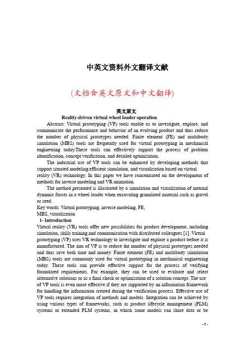
中英文资料外文翻译文献(文档含英文原文和中文翻译)英文原文Reality-driven virtual wheel loader operationAbstract: Virtual prototyping (VP) tools enable us to investigate, explore, and communicate the performance and behavior of an evolving product and thus reduce the number of physical prototypes needed. Finite element (FE) and multibody simulation (MBS) tools are frequently used for virtual prototyping in mechanical engineering today.These tools can effectively support the process of problem identification, concept verification, and detailed optimization.The industrial use of VP tools can be enhanced by developing methods that support situated modeling,efficient simulation, and visualization based on virtual reality (VR) technology. In this paper we have concentrated on the development of methods for inverse modeling and VR animation.The method presented is illustrated by a simulation and visualization of internal dynamic forces in a wheel loader when excavating granulated material such as gravel or seed.Key words: Virtual prototyping, inverse modeling, FE,MBS, visualization1- IntroductionVirtual reality (VR) tools offer new possibilities for product development, including simulation, skills training,and communication with distributed colleagues [1]. Virtual prototyping (VP) uses VR technology to investigate and explore a product before it is manufactured. The aim of VP is to reduce the number of physical prototypes needed and thus save both time and money. Finite element (FE) and multibody simulation (MBS) tools are commonly used for virtual prototyping in mechanical engineering today. These tools can provide effective support for the process of verifying formulated requirements. For example, they can be used to evaluate and select alternative solutions or as a final check or optimization of a solution concept. The use of VP tools is even more effective if they are supported by an information framework for handling the information created during the verification process. Effective use of VP tools requires integration of methods and models. Integration can be achieved by using various types of frameworks, such as product lifecycle management (PLM) systems or extended PLM systems, in which some models can share data or beassociated with each other, as in CAD-FE models. An approach to such a research framework is described in the MOSAIC project (e.g. [2]) and [3]) which has been further developed in the VISP project (e.g., [4], [5] and [6]). One interesting research area that these frameworks also address is how to capture not only the data but also the knowledge that is generated during a development project so that it can be re-used in another project or used to explain changes in an existing product. This research area also deals with traceability (i.e., how to find information created earlier); design rationale (i.e., the reason for a certain design shape or design decision); and decision support (i.e., the use of one or more methods to draw a conclusion based on the stored structure of information – i.e., formal knowledge – that is presented to the user).2 - ResearchThe research presented in this paper was undertaken in collaboration with V olvo Construction Equipment (V olvoCE), which supplied the industrial problem and environment. V olvo CE also contributed models and realistic data about working conditions. All other research was performed at KTH in the Department of Machine Design.2.1- V olvo Construction Equipment (V olvo CE)V olvo CE is one of the world’s leading producers of construction machines, with a product range that includes wheel loaders, excavators, articulated haulers, and motor graders. The V olvo wheel loaders are designed and manufactured on four continents. The new range of V olvo wheel loaders uses modern technology, such as loadsensing hydraulics, service accessibility, TP-linkage, the Care Cab, automatic power shift, and high-performance and low-emission engines to combine increased performance with improved operator comfort and reduced environmental impact.Figure 1: A wheel loader from Volvo CE [7]Because wheel loaders are heavily loaded during normal operation, accurate prediction of strength and fatigue is a high priority. Moreover, because machines canbe customized for specific operations, the required performance and behavior of each customized loader is unique. Consequently, the behavior of the complete system must be considered when studying the strength and reliability of the components, and the behavior of the components constrains the performance and reliability of the system.2.2 - Research focusAt V olvo CE a highly systematic procedure based on physical and virtual testing is used to predict the strength and fatigue life of individual components. However, it is considered strategically important to improve the ability to study the virtual behavior of a system of components or subsystems, or in other words, the behavior of more complete vehicles. A first step in that direction is to expand and integrate the use of existing MBS and FE tools.One interesting research challenge is to develop a methodology that supports modeling of components and subsystems and enables reuse of models for different analyses. In considering this problem, we will concentrate on the use of FE and MBS models. Another important issue is how to assemble MBS system models that need to have elastic components (which we can import from FE models) in order to enable high-quality simulations of complete vehicle dynamics behavior, as well as operator comfort related to noise and vibration.The development of complex products requires simultaneous consideration of several aspects and draws on a multitude of competencies. It is thus important that any methodology developed should also include suitable ways to present and communicate simulation results. We believe that animation of motion geometry and property graphs as well as scaled force and torque arrows can be an important complement to more traditional means of communication.2.3 - Research realizationThe research reported here focuses on the evaluation and verification of design concepts that takes place continuously and iteratively during the design process. Our approach to this research topic has been to treat it as part of the design process. The evaluation process can be characterized as an exploratory process that is built around questions and answers until all principal uncertainty about a concept has been revealed (i.e., the complexity is managed).The modeling approach that has been chosen is a systems approach, in which parts are treated as subsystems that can be connected at specific connection points. The configuration of the system models to be simulated is then a part of the evaluation process. The work presented here centered on an industrial application, namely a wheel loader from V olvo CE performing a digging operation in a pile of granulated material. This application has been used to guide the research as we have sought to develop a methodology for simulation-assisted decision-making in the design process and enabling areas. Thus we have examined•methods for architecting modular system models and configuring reusable and modular simulation models.•methods for integrating measurements with simulation model experimentation in general and inverse modeling in particular.•methods for presenting and communicating the results of simulations.3 - Decision-makingA general though rough description of a design process is the stage-gate model, in which the process is divided into a number of predefined phases with gates between them. Decisions are taken continuously during the design work, but major decisions are concentrated at the predefined gates between major design activities or phases. The activities between the gates are focused on detailing and resolving uncertainties about the actual concept, that is, on gaining knowledge about the concept. These activities are triggered by the specifications that define the target values for the properties of the proposed product.The activities can all be seen as part of a verification process that iteratively evaluates all critical requirements, either by simulating behavior or by using other sources ofinformation, including colleagues and old designs. In this paper we are focusing on the use of simulation and simulation models as a tool to make this evaluation process more efficient.In figure 2, we have illustrated the concept verification process taking place between two gates in the development process. The main activity in this process is “investigate problem”, w here the problem is whatever is unknown about a requirement and needs to be further investigated.The database symbols indicate that for each step in this process there are a number of predefined models that maybe candidates for use in solving an actual problem.3.1- Model Architecting and ConfigurationAn important part of the verification process is the ability to configure system models, each adapted to perform a specific task, and each consisting of models of componentsand subsystems. To be able to analyze this system, there must also be a feasible level of detail and a feasible simulation tool.To achieve this goal, the product concept being studied must be divided into components and subsystems that can be modeled separately. Models of components and subsystems are both referred to as subsystem models in what follows.We also need to define a way to configure system models from these subsystems models. Our approach is based on identifying and representing the connections between subsystem models (see [8]). In discussing these connections, we refer to the connection point at the subsystem as the mating feature, and the physical connection as the interface feature. Figure 3 shows a system model of a lifting unit comprising subsystem models that are connected by interface features at the specified mating positions. A mating feature may be a discrete point or a set of points representing one (or several) surface(s) on the component. An interface featuremay be a set of constraint equations or a more complex model, as is indicated for one of the joints in figure 3.Figure 3: A lifting unit in a wheel loader composed o submodels conne fcted by interface featuresFigure 4: Models of a wheel loader lifting frame with different levels of detailThis modeling approach has great potential, but to take full advantage of it we need to define more than one variant, and preferably two or three, of most subsystems. These variants may have different levels of detail and may be targeted for different software tools. These variants are the main precondition for setting up a system model that is suited to exploring the question (formulated as a problem) of how behavior will be affected by a property of a product concept. Figure 4 shows some wheel loader lifting frame models and their mating features with different levels of detail.The exploratory nature of the verification process outlined in figure 2 results in corollary problems arising from the problem initially stated. The sequence of problem tasks and questions places demands on the modeling environment to make it easy to configure new or partly new configurations of system models. A typical problem sequence starts with a defined problem, which requires a rather rough model of the overall behavior of the concept, (e.g. a complete vehicle). A corollary problem will then involve either more focused analysis of a portion of the entire system, or a more detailed analysis of the total system. Both these corollary problems require new system models to be configured. For example, if a more focused analysis is called for, attention would focus only on the lifting unit, and some of the subsystem models would probably be replaced with more detailed models. The calculated forces in theinitial system model would be the boundary conditions for this analysis. If it is the total system that needs to be examined, as would be the case if we wanted a more detailed study of the behavior of a subsystem working within the total system or the impact of one component on the behavior of the total system, then some subsystem models would need to be replaced with more detailed models.The modeling approach presented in this paper makes it possible to reuse some of the subsystem models when tackling both these corollary problems.3.2 - Inverse modelingIn many cases, not all the parameters of a system model are known or can be obtained directly from measurements. If measurements are used to infer the values of parameters on which the measurements themselves depend, we have an inverse measurement problem, which from now on will be referred to as an inverse problem. The estimation of these parameters or functions requires both a model and measurements [9]. This technique has been widely applied in the environmental sciences (e.g., [10]). The size of real industrial problems and the disparate scales involved, as well as the nonlinear and often poorly formulated nature of inverse problems, mean that inverse modeling is among the fundamental challenges facing computer-aided engineering. Any solution will require the joint effort of computer scientists and engineers. However, this issue falls outside the scope of the present paper, which focuses on methodological issues.Inverse modeling, or parameter assessment, may be seen as an optimization problem in which the error between measured and simulated data is the objective function S that is to be minimized. If the standard statistical assumptions given in [11] are valid, then an ordinary least Squares objective function is appropriate [9]:where Yi denotes a measured quantity, and i Y a calculated model value at a time, location, or other space indicated by i. It is also possible for i to denote a given measurement in time or space. The collections of all measured andcalculated values are denoted Y and Y , respectively.In modeling dynamic behavior, a dependent variable such as the frequency of the first bending mode of the vehicle can be measured at one or more positions. However, some basic parameter, such as the bending stiffness of the front and rear frame and of the joints that connect the two frames, may not be known. If the frequency and the mass distribution are known, this parameter can be determined with a model that accurately represents the fundamental dynamic properties of the individual components.Simulation models may also suffer from a lack of accurate descriptions of the surrounding external interactions with the model. When testing a prototype, some of the important and critical loads may be very hard or even impossible to measure. Inverse modeling offers one solution to this dilemma by allowing us to combine measurements from experimental tests and simulation models. The measurements are used as driving conditions that control the simulation model, with which the requestedinternal properties can be calculated.A first approach to describing a method for inverse modeling involves the following steps:•Decide whether inverse modeling is necessary or whether traditional experimental testing or a simulation approach will be adequate for the task inhand.•If inverse modeling is necessary, identify the interior object states and changes of state that cannot be measured in experimental tests.•Configure a system model based on subsystem models that are connected at predefined positions (mating features) by connecting elements (interface features).•Identify the boundary conditions that need to be measured in order to drive or control the simulation model.•Develop expressions or models for external interaction forces that cannot be measured.•Perform the analysis and calculate the interior loads. This approach fits very well in the verification loop in figure 2. A closer view of the activity “investigate problem” is given in figure 5.Figure 5: The activity “investigate problem”The proposed method applies to activities two (create behavior system) and three (simulate behavior) in figure 5. After simulating the behavior, it is critical to interpret the results and verify that the simulation gives a correct and sufficiently accurate reflection of the studied properties.Consequently when we are planning experimental studies,we should also consider what properties we should measure in order to be able to verify the results obtained using the simulation.The remaining activity in the verification task in figure 5 is to formulate an answer to the initial problem. As indicated in the figure, this answer can also be based on answers from earlier analyses.3.3 - Presentation of simulation resultsBoth when interpreting results and when formulating answers, it is important to select the most appropriate way to present the simulation results. This is a strategically important issue for successful communication and collaboration inteam-based development of complex products.During simulation, a lot of results are created and saved in special results files. A common way to analyze simulation results has been to plot graphs of selected properties at interesting (critical) positions in the product. This approach has been applied in simulations since the late 1960s when we started to use these types of computer tools. However, developments in hardware and software now provide far more powerful ways to present simulation results. We can now, for example, show an animation of a work cycle of a robot or of the eigenmodes of a component.The ability to animate product behavior and to identify critical states during operation brings a new dimension to presenting results. The animation can include many other components besides motion geometry and property graphs,including scaled force and torque arrows to indicate component and interacting loadsduring a work task.Such animations permit more team-centered discussion ofwhat is actually happening in the conceptual design during the simulated operation and give a common understanding among the team members. They can also shorten the iteration loop and development time because this type of qualitative evaluation demands very little preparation before the team discussion.We suggest that animation should be used to present and obtain an immediate response before the answer is formulated. When it comes to formulating the answer, we also think that animation of internal interactions as well as of global systems behavior play an important role as a complement to more traditional documentation with text and graphs.4 - Case Study: A wheel loader digging sequenceIn order to illustrate the work approach outlined in this paper, we have studied a digging sequence of a wheel loader. The problem is to calculate loads in three bearings of the lifting unit during digging in a pile of granulated material and loading it on a truck.This is the initial problem statement – a formulation that is based on the stated requirements, actual design concept, and previously defined and solved problems that can be examined and compared to existing conditions. In this case, the design concept is not unknown since the task relates to improvement of an existing product.Next we have to decide how to solve the problem and to come up with an answer. At this stage, we need to find out whether we need to use inverse modeling as described earlier. The components of interest are bearings G, D, and F (see figure 6).Figure 6: The location of bearing G, D and FThese component loads cannot be measured during an experimental study. It is also hard to derive them solely from simulation models, which would require an accurate description of external conditions in order to achieve acceptable simulation results. Thus we do need to use inverse modeling.4.1 - Modeling approachWe have chosen to study a model of a complete vehicle and to use the inverse modeling approach combining measured properties and numerical simulation tools. The vehicle has been modeled in the ADAMS modeling environment. The model is based solely on rigid bodies connected by kinematic joints and force elements [12]. The first bending mode of the vehicle is represented by an elastic interface feature connecting the front and rear frames of the vehicle. This elastic interface feature is modeled using force elements. The parameters of the interface feature representationare assessed using the inverse modeling technique described earlier. The systems model comprises a total of 50 rigid bodies. The surrounding environment gives the external interaction conditions, which in this case are•the wheel contact against the ground, and•the contact with the pile of granulated material.The wheel contact is handled by using an available tire model in the chosen modeling environment (ADAMS).The parameter values of the tire model are also obtained with inverse modeling of the measured fundamentalvertical eigenfrequencies of the vehicle. Eriksson and Slättengren [13] have developed a separate subroutine for describing the interaction between the bucket and the pile of granulated material. This routine has been implemented in ADAMS as a general force subroutine (GFOSUB), which calculates all six generalized component forces.In order to drive the simulation model, we need to measure the lift and tilt angle of the lifting unit as well as the steering angle and propelling velocity on the drive shaft. With these measured values, we can control the motion and turning (propelling velocity and steering angle) of the vehicle as well as the digging (lift and tilt angle). In addition we need to measure some properties to use for validation and verification of the simulation model. Here we choose to measure forces in the lift and tilt cylinders and the torque on the drive shaft. Figure 7 shows a wheel loader in the experimental test case and the corresponding ADAMS model.4.2 - Preprocessing of measurementsRecording the measurements with a sampling frequency of 500 Hz generates too much data to be practically handled by a simulation tool. It also includes a frequency spectrum containing higher frequencies (>30 Hz) than we are interested in for this study. Consequently we have to perform some presimulation processing of the measured signals by applying a low-pass filter and resampling the signals to 50 Hz. This processing adapts the signals to fit the ADAMS modeling environment in general and this vehicle model in particular.Furthermore, angular measures of steering lift and tilt need to be translated into corresponding cylinder lengths for the actuators that are generating this movement. This can be done by performing a kinematic analysis of the ADAMS models using the angular measurements to control the angle of the actual rotational joint. During this simulation the length of the actuators is calculated (i.e. Inverse modeled) and saved so that this data can be used as input to the inverse simulation of the vehicle.A first direct response of the simulation is of course given the engineer performing the simulation. A second responsecan easily be obtained from the project team if an animation of reaction forces during the simulation is prepared and used as a base for a qualitative evaluation. Figure 8 shows a snapshot of the animation of the vehicle at a point when the bucket is entering the pile. It clearly shows that the reaction force in bearing D is the largest of those three being studied. It also shows that the size is almost double that of the force in bearing G and three times that in bearing F. An animation will also illustrate how these forces vary during the simulated work cycleFigure 8: A snapshot during animation of reaction forces inG, D, and F bearingsThis qualitative approach to the reaction forces is presented in quantitative terms in figures 9 to 11.The final ta sk in the outlined activity “investigate problem” in figure 5 is to use these findings to formulate an answer to the question about the loads in bearings G, D,and F. The content of this answer is preferably an aggregation of animation(s) of the bearing loads, as shown in figure 8, the force history graphs in figures 9 to 11, anda short discussion of the interpretation of these results.4.4- Validation and verification of simulation modelBefore formulating the answer, we have to verify (is the model right?) and validate (is this the right model?) our simulation model so that we can conclude whether or not our results and conclusions are correct and accurate enough. The required accuracy is context dependent, and sometimes a qualitative result is sufficient. In other cases,a detailed result is sought.During the experimental study we prepared for the verification phase by measuring additional properties to those needed solely to drive the simulation. Of these measurements, we will use output torque on the propelling shaft and cylinder forces in the lift and tilt cylinders to validate the simulation model and verify our simulation results.A comparison of the measured values and the corresponding simulated values is shown in figures 12 to 14.For the lift and tilt cylinders, we can see that we have goodcorrelation for the phase from five to seven seconds andacceptable correlation for the rest of the work cycle for the lift cylinder. For the tilt cylinder, however, we find a significant deviation during the phase from ten to eighteen seconds. After ten seconds, the bucket is tilted against its end stop and the cylinder valve is closed. This is why the cylinder force is almost constant during this period – the slightly decreasing force is probably due to a small leakage in the hydraulic system. Since the hydraulics are not represented in the simulation model, this is a plausible explanation of the relatively low correlation during this phase.5- DiscussionA decision support system is intended to reduce uncertainty about a concept and its behavior. The natural way to do this is to formulate questions about what we do not know. These questions may concern specific properties as well as overall behavior. To handle such questions, we need a model architecture that enables easy configuration of a simulation model that is targeted at the formulated question. To enhance model performance, a system simulation model is preferably a mixed-fidelity model [8]. The correctness of simulation results must always be judged in relation to the purpose for conducting the simulation, that is, the actual question that has beenformulated. With its modular model architecture, the simulation model used in the presented case study can easily be made more detailed by, for example, including a submodel of the hydraulic system, and by exchanging one or several of the rigid bodies with elastic submodels imported from FE software such as ANSYS [14] that has capabilities for dynamic condensation, e.g. the Craig- Bampton approach [15] which is interoperable with ADAMS. Model-based design reasoning and simulation-assisted decision-making require situated modeling [16]. In other words, the model must be easy to reconfigure and optimize for a new purpose (i.e. the model must be adapted to the present situation in the development process). Assume,for example, that a question relating to operator comfort is raised after the digging simulation presented above has been performed, communicated, and discussed. A modular model architecture allows the simplified subsystem model of the cab and its connection to the front frame to be replaced with more detailed model variants of the cab andof the interface features of the vibration isolators. Animations (and otherVR-related techniques) that simulate behavior significantly help the simulation engineer to interpret and understand the simulated behavior and the different phases of that behavior. Consequently, communication and team-based design reasoning and model verification and validation benefit from VR animations.6- ConclusionsThis paper presents a model of decision support that systematically utilizes VP in the decision process. The methods underpinning this model have been developed and together they provide a basis for a methodology for a simulation-assisted decision process. This methodology comprises methods for•architecting modular system models and configuring reusable and modular simulation models•integrating measurements with simulation model experimentation in general and inverse modeling in particular•presenting and communicating simulation resultsA modular model architecture is a main precondition for easy configuration of a simulation model for each question that arisesIntegrating measurements and simulation modeling is very valuable for some simulation tasks where inverse modeling and inverse simulation offer significant advantages. This is often the case when modeling complex systems and behaviors, where some properties cannot easily be measured and others are difficult to define a priori.Animation of a product’s behavior can be a powerful tool for presenting simulation results, for example by using scaled force and torque arrows to indicate component and interacting loads during a work task. Such animations promote a qualitative evaluation of simulation results that is preferable in team-centered discussion and also give a faster indication of the correctness and feasibility of the model.This methodology has been applied in an industrial test case involving the dynamic behavior of a wheel loader from V olvo CE. The results so far are promising but tentative. We plan to further test and develop the methodology in upcoming projects. 7- AcknowledgementsThe authors wish to thank Allan Ericsson at V olvo CE for assisting with the simulations as well as for measurements on the wheel loader.。
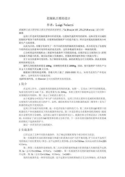
挖掘机吕臂的设计作者:Luigi Solazzi机械和工业工程学院工程大学布雷西亚研究,Via Branze 38, 25123 Brescia,(意大利)摘要这项工作是研究挖掘机臂和吊杆的发展,以便取代通常所用的材料。
这种改变可以减轻挖掘机铲臂各个部件的重量,以便增加挖掘机铲斗的提升能力。
所以这对提高挖掘机每小时的生产力很重要。
以此为目的,用数字化研究了一些不同的传统挖掘机的负载情况,其目的是为了估量每个组件的安全因素和可变形性或者说灵活性。
这些参数被用来设计一种新的机臂。
已分析的这些挖掘机由三要素和负载条件下的假设组成,以便评估五方面的应力(距转动轴最大和最小距离、液压缸的最大负载感应、挖掘机臂的旋转和抗干扰能力等)。
至于安全因素和可变形性,为了维持原有的值,新的机臂包含尺寸的增加,因此重量跟材料的密度无关。
最终几何机臂的重量是108kg,而钢臂的重量是2050kg,因此,他可能将铲斗的生产力从1立方米提升到1.35立方米。
根据新吕臂的制造周期,价格大约上涨了2500-3000欧元,如果考虑到生产率提高35﹪,这种状况有可能被改观。
©2010 ISTVS。
由Elsevier公司出版的所有权利保留。
1简介在这项工作中,已被检查的挖掘机是传统的机器,如图一。
它是由三种不同的臂构成,每部分的功率为110千瓦,额定重量为21.500kg。
本机主要用于拆除和运送关于民用和工业领域的应用材料。
图一显示了本机的主要尺寸。
由于机器每小时的生产率与铲斗的容积有关,这项工作的主要科目是减轻机臂的重量,以便使用与原来相比更大的铲斗。
显然,减轻机臂而不涉及到机器的底部(履带车)是为了机器的稳定性不受到危害。
这项工作分成不同的步骤。
地一步是评估每个部件的尺寸;第二步涉及到CAD模型下的机器的生产和对满载状况下的负载条件的评估。
第三步是估算安全系数和原机的刚度(随着铝合金臂代替合金钢臂,这些值已被用于新的组件设计)。
本科毕业设计外文文献及译文文献、资料题目:Loader Overview文献、资料来源:互联网文献、资料发表(出版)日期:院(部):机电工程学院专业:机械工程及自动化班级:机械姓名:学号: 2指导教师:翻译日期:外文文献:Loader OverviewThe main function of the loader shovel of loose material and short-distance transport operations. It is the fastest growing engineering machinery, machine production and sales and market demand one. We usually see the largest wheel loaders, it is acrawler loaders. Crawler than it has good mobility, does not destroy the road surface, easy to operate, etc.. Wheel loaders has been widely used.A loader (also known as: bucket loader, front loader, front end loader, payloader, scoop loader,shovel, skip loader, and/or wheel loader) is a type of tractor, usually wheeled, sometimes on tracks, that has a front-mounted square wide bucket connected to the end of two booms (arms) to scoop up loose material from the ground, such as dirt, sand or gravel, and move it from one place to another without pushing the material across the ground. A loader is commonly used to move a stockpiled material from ground level and deposit it into an awaiting dump truck or into an open trench excavation.Loaders in general by the chassis, powertrain, running gear, working device, steeringbrake, hydraulic system and operating system.The basis of the loader classification is the Society of Automotive Engineers of America (SAE) rated capacity of the bucket. The classification is based on the largest general purpose bucket offered by the manufacturer or the bucket size adopted by the Contractor, whichever is the loader assembly may be a removable attachment or permanently mounted. Often the bucket can be replaced with other devices or tools—for example, many can mount forks to lift heavy pallets or shipping containers, and a hydraulically opening "clamshell" bucket allows a loader to act as a light dozer or scraper. The bucket can also be augmented with devices like a bale grappler for handling large bales of hay or straw.Large loaders, such as the Kawasaki 95ZV-2, John Deere 844K, Caterpillar 950H, V olvo L120E, Case 921E, or Hitachi ZW310 usually have only a front bucket and are called Front Loaders, whereas small loader tractors are often also equipped with a small backhoe and are called backhoe loaders or loader backhoes or JCBs, after the company that first invented them.The largest loader in the world is LeTourneau L-2350. Currently these large loaders are in production in the Longview, Texas facility. The L-2350 uses a diesel electric propulsion system similar to that used in a locomotive. Each rubber tired wheel is driven by its own independent electric motor.Komatsu-integrated design offers the best value, reliability, and versatility. Hydraulics, powertrain, frame, and all other major components are engineered by Komatsu. You get a 18machine whose components are designed to work together for higher production, greater reliability, and more versatility. Komatsu’s highly productive, innovative technology, environmentally friendly machines built for the 21st century.Loaders are used mainly for uploading materials into trucks, laying pipe, clearing rubble, and digging. A loader is not the most efficient machine for digging as it cannot dig very deep below the level of its wheels, like a backhoecan. The capacity of a loader bucket can be anywhere from to 36 m3 depending upon the size of the machine and its application. The front loader's bucket capacity is generally much bigger than a bucket capacity of a backhoe loader.Unlike most bulldozers, most loaders are wheeled and not tracked, although track loaders are common. They are successful where sharp edged materials in construction debris would damage rubber wheels, or where the ground is soft and muddy. Wheels provide better mobility and speed and do not damage paved roads as much as tracks, but provide less traction. In construction areas loaders are also used to transport building materials - such as bricks, pipe, metal bars, and digging tools - over short distances.Front loaders are commonly used to remove snow especially from sidewalks, parking lots, and other areas too small for using snowplows and other heavy equipment. They are sometimes used as snowplows with a snowplow attachment but commonly have a bucket or snowbasket, which can also be used to load snow into the rear compartment of a snowplow or dump truck. High-tip buckets are suitable for light materials such as chip, peat and light gravel and when the bucket is emptied from a height.Loaders bucket characteristicsedge for super-hard wear resistant steel plate up to 500 Brinell hardnessfor long life.shell and side Brinell hardness of 400 to resist abrasive wear. Installed bythe enhancedtreatment of attachment hinge points to reduce Wear and tear.cutting blade for resistance to abrasive wear of steel, Brinell hardness of 500. Resistantliner installed in the bucket on the floor byThe bolt may be replaced, the Brinell hardness of 500.4. bolt and the edge of savings and staging to prevent unnecessary wear of thecutting edge.5. V olvo bucket tooth system is equipped with a bolt or weld type connector, theBrinellhardness of 515, with best interpolation into the depth and the smaller the wear and tear.Skid-steer Loader Features1. The round-back bucket design is stronger with no angled corners. This configuration makesit easier to fill and dump —improving productivity.2. The ROPS/FOPS structure protects and shields the operator.3. A total of four exterior lights help to illuminate any job site day or night.4. A safety system locks lift, tilt and drive systems when the operator leaves the seat, raisesthe seat bar, or turns off the ignition switch. The brakes are wet-type multiple discs that require no maintenance.5. Heavy-duty tires are standard —matching the durability of the skid-steer.6. The rugged all-welded unitized frame is constructed of .375-inch gauge steel for years ofproductivity. Step bushings are placed in all key pivot areas to increase strength and reduce stress.7. A wider wheelbase provides for a smooth ride and more balance for stability with heavierloads. A 9-inch ground clearance allows easy maneuverability through mud and other terrain.8. Hydraulic lines are protected within the loader arm.9. Mustang features a self-leveling vertical lift.10. The advanced hydraulic system affords longer service intervals and comes with a sight glass for quick and easy fluid level inspections.11. A drop-down step makes it convenient to check engine and maintenance Points.This wheel loader offers two selectable engine operating modes —Normal and Power. The operator can adjust the machine’s engine performance to match the condition requirements.This system is controlled with a dial on the right side control panel.(1)Normal Mode: provides maximum fuel efficiency for most general loading conditions. (2)Power Mode: provides maximum power output for hard digging conditions or hill climb operations.2 Automatic Transmission with Four Mode Select SystemThis operator controlled system allows the selection of manual shifting or three levels of automatic shifting modes (low, medium, and high). The operator can match the machine’s operating requirements with optimum performance efficiency. This system is controlled with a dial on the right side of the control panel.(1)Manual: The transmission is fixed to the gear speed and selected with the gear shift lever.(2)Auto Low: Low mode provides smooth gear shifting at low engine speeds suitable for general excavating and loading while offering reduced fuel consumption.(3)Auto Medium: Medium mode provides gear shifting at mid-range engine speeds required for more aggressive conditions.(4)Auto High: High mode provides maximum rim pull and fast cycle times by shifting the transmission at high engine speeds. This mode is suitable for hill-climb and load and carry operations..Unlike backhoes or standard tractors fitted with a front bucket, many large loaders do not use automotive steering mechanisms. Instead, they steer by a hydraulically actuated pivot point set exactly between the front and rear axles. This is referred to as "articulated steering" and allows the front axle to be solid, allowing it to carry greater weight. Articulated steering provides better maneuverability for a given wheelbase. Since the front wheels and attachment rotate on the same axis, the operator is able to "steer" his load in an arc after positioning the machine, which can be useful. The tradeoff is that when the machine is "twisted" to one side and a heavy load is lifted high, it has a greater risk of turning over to the "wide" side.Front loaders gained popularity during the last two decades, especially in urbanengineering projects and small earthmoving works. Heavy equipment manufacturers offer a wide range of loader sizes and term "loader" is also used in the debris removal field to describe the boom on a grapple truck.The Israeli Combat Engineering Corps use armored Caterpillar 966 wheel loader for construction and combat engineeringmissions in hostile territories such as the West Bank. They are often seen building or removing road blocks, building bases and fortifications and starting in 2005, demolishing small houses. The IDF added armor plating for the loader, protecting it against rocks, stones, molotov cocktails, and light gunfire.Rio de Janeiro's police elite squad BOPE have recently acquired one wheel loader of military purposes to open routes and make way for the police in Rio de Janeiro's slums, which are controlled, and blocked, by drug dealers.These loaders are a popular addition to tractors from 50 to 200 hp. Its current 'drive-in' form was originally designed and developed in 1958 by a company called Quicke. They were developed to perform a multitude of farming tasks, and are popular due to their relatively low cost (compared toTelehandler) and high versatility. Tractor loaders can be fitted with many attachments such as hydraulic grabs and spikes to assist with bale and silagehandling, forks for pallet work, and buckets for more general farm activities.Popular additions to compact utility tractors and farm tractors are Front End Loaders, also referred to as a FEL. Compact utility tractors, also called CUTs are small tractors, typically with 18 to 50 horsepower (37 kW) and used primarily for grounds maintenance and landscape chores. There are 2 primary designs of compact tractor FELs, the traditional dogleg designed style and the curved arm style.John Deere Tractor manufactures a semi-curved loader design that does not feature the one piece curved arm, but also is not of the traditional two piece design. New Holland Ag introduced a compact loader with a one piece curved arm on its compact utility tractors, similar one piece curved arm loaders are now available on compact tractors on many brands including Case/Farmall, and some Montana and Kioti tractors. Kubota markets traditional loader designs on most of its compact tractors but now features a semi-curved loader design similar to the John Deere loader design on several of its small tractors.While the Front End Loaders on CUT size tractors are capable of many tasks, given theirrelatively small size and low capacities when compared to commercial loaders, the compact loaders can be made more useful with some simple options. A Toothbar is commonly added to the front edge of a loader bucket to aid with digging. Some loaders are equipped with a quick coupler, otherwise known as a Quick Attach (QA) system, the QA system allows the bucket to be removed easily and other tools to be added in its place. Common additions would include a set of Pallet Forks for lifting pallets of goods or a Bale Spear for lifting hay bales.A skid loader is a small loader utilizing four wheels with hydraulic drive that directs power to either, or both, sides of the vehicle. Very similar in appearance and design is the track loader, which utilizes a continuous track on either side of the vehicle instead of the wheels. Since the expiration of Bobcat's patent on its quick-connect system, newer tractor models are standardizing on that popular format for front end attachments.A swing loader is a rigid frame loader with a swinging boom. The boom can swing 180 degrees or more. Swingloaders are primarily used by the railroad industry to lay rail. Like other loaders many attachments can be attached to the boom such as magnets, forks, and buckets. Smaller swingloaders are used in farming applications for loading out. A swinging boom is advantageous where space is limited. The loader is able to lift on all sides and dump off on all sides.At present, foreign multi-functional logistics equipment and related technologies are increasingly improved, and development series, large-scale, miniaturization, multi-purpose and other direction. Internationally renowned manufacturers (such as Lynx, Case, Caterpillar, Komatsu, liebherr, V olvo, etc.) widely used in microelectronics and information technology, and improve computer-aided driving systems, information management systems, such as the application of electronic monitoring and automatic alarm system, materials used for precision fitted, upload, GPS positioning and weight of the operation of industry automatic weighing device; the use of special noise reduction materials, noise suppression to eliminate or reduce machine noise in the loader work; through continuous improvement EFI devices to further reduce exhaust emissions of diesel engines, non-polluting, economical, environmentally friendly power plant; optimize the structural design of the working device, such as a single "Z"-type linkage evolution of the eight parallel institutions, TP linkage and ERASLINK "institutions (single-action arm cast steel structure), and O & K is designed specifically for small multi-function loaderLEAR linkage in order to improve the operating productivity of the loader, have developed many of the features ultra- strong systems, such as: power electronics control / management system automatically adjusts the engine output power; engine automatic control system, when the loader in a non-working condition, automatically reduces engine speed, reducing fuel consumption and engine noise; key information display systemand so on. Loader industry leading products are basically developed in the early 1970s Liugong ZL50-based development, an international technical level of the 1960s. In the 1980's digestion and absorption of advanced technology in the United States, Caterpillar, Komatsu of Japan, and gradually the successful development of the second generation wheel loader. Compared to China's second-generation products with international advanced products in the mechanical and electrical integration, manipulation of comfort, operating efficiency, a wide gap between the biggest gap is the product reliability, domestic multi-function loader machine reliability (average time between failures is less than 400 hours), lack of core technology and key components are imported, and products a single, low-grade products. Although domestic loaders and related technical work started late, but soon the pace of development, such as multi-function loader sales have accounted for half of the loader market in the world, China has become the world's multi-function loader production and marketing power.China Loader Industry has the third-generation products. The third-generationmachine reliability is greatly improved, the main performance indicators largely withthe international advanced level. However, in reliability, comfort, operational efficiency and manufacturing levels of baking and foreign advanced level there is a considerable gap. Fourth-generation product in the third generation on the basis offurther optimization of the overall performance and configuration, the electric control box, wet brake technology has been applied, and formed a proprietary technologyand patented technologies in enterprises, so that product with a new face to the market. These will further promote the technological progress of China's loader industry.Microelectronics and information technology will be widely used, further improve thecomputer-aided driving systems, information management systems and fault diagnosis system; single sound-absorbing material, the noise suppression methodsto eliminate or reduce machine noise; through continuous improvement of the fuel injection device further reduce exhaust emissions of diesel engines. In addition tothese, but: multifunctional bucket, ripper, liquid Villagehammer, snow, etc. a variety of devices, small size, power, lightweight and flexible, and better fuel economy, increased cab size and glazing area, improve the indoor air pressure to the dust, to improve the control system and the joystick position to improve the operating environment of comfort, reduce the operator's labor intensity, and beautify theappearance. Particular because of China's mining loader started late, whether it isproduct variety, performance parameters, or the use of reliability, after-sales serviceand so on, and abroad there is a considerable gap. Therefore, the trend of its development is the introduction of foreign advanced technology to develop high-quality, multi-functional, multi-species, multi-standard range of products to increase market competitiveness; strengthen basic components, parts production and quality, in particular, is to improve the hydraulic the quality of the components, in order to achieve to meet the requirements of the premise of the product reliability,reduce product cost; improve the quality of service products.Half of the market, China has become the world's multi-function loader production and marketing power.中文译文:装载机概况装载机是一个通常用于建筑的重型设备,主要用于将材料(等asasphalt,拆除杂物,灰尘,雪,饲料,砾石,原木,矿物原料,再生材料,岩石,沙,木屑)装入另一种类型的机械(如自卸车,输送带,进料斗,或车厢)。
Development of a walking machine: mechanicaldesign and control problemsTeresa Zielinska *, John HengAbstractThis paper describes: a novel design of the leg drive mechanism, hardware architecture and the leg control method for a walking machine being developed to study various walking gait strategies. The leg mechanism employs an inverse differential gear drive system providing large leg lift and swing sweep angle about a common pivotal point while being driven collectively by a pair of motors。
The development platform consists of a pair of legs mounted adjacently to each other on a linear slide。
A three—axis piezo transducer is mounted on the feet to measure the various vector forces in the legs during the support phase. The force sensing results are presented and discussed。
Currently one small four-legged prototype and one hexapod are used for the tests of different gait patterns. _ 2002 Elsevier Science Ltd. All rights reserved. Keywords: Walking machines; Mechanical design; Control system design; Force sensing1. IntroductionIn comparison with the industrial manipulators, the task of building an adaptable, autonomous walking machine is more difficult. Walking machines have moreactive degrees of freedom (DOF) than industrial robots. To enlarge the work—space of the leg-end, and thus enhance the machine’s ability to adapt to the terrain, each leg should have at least three DOF, which results in a total of 12 DOF for a quadruped or 18 DOF for a hexapod。
中英文对照资料外文翻译文献附录一中文翻译轮式装载机的典型20 世纪 20 年代,小型农用拖拉机都配备的轻质材料 re-handling 装载机铲斗。
这难以置信担任现代轮式装载机的最早的原型。
轮式装载机的最早版本是旋转桶和电梯武器装载上农场型拖拉机。
一桶装上拖拉机离合器的绞盘,通过使用金属丝绳,然后甩重力了通过旅行释放机制。
20 世纪 30 年代,多家厂家正在发展小型轮式装载机的紧固水桶到拖拉机上。
科技公司在英国曼彻斯特,桶装的拖拉机的他们缪尔山加载程序的第一次录制制造商之一,28 马力拖拉机装入 0.5 立方码 (0.4 m3) 电缆控制斗。
刚性框架轮式装载机1939 年,来自芝加哥的一位工程师弗兰克 G.霍夫的名称,开发第一个自包含、两轮驱动、橡胶累了、装载机称为 Hough 模型 HS。
这台机器了斗容量的 1/3 立方码(0.25 m3)。
桶重力通过闩锁机制被甩了。
其他制造商开始生产综合四轮驱动轮式装载机。
许多第一次的轮式装载机的有刚架。
虽然这些机器被集成在一起,他们刚架有限导致要转大圆圈损在严密的地方经营的机的操纵性能。
由毛毛虫,开发的第三个轮式装载机,例如了刚架。
其他制造商喜欢欧几里得 / 特雷克斯轮式装载机市场中输入 1957 年较晚,与小刚架轮式装载机单元称为L-7。
古河 FL35I 4 x 4 铰接式装载机也许在轮式装载机的演变中的最重要里程碑之一是铰接架的介绍。
厂商在俄勒冈州波特兰首创这一技术在 1953 年模型 LD-5,在 1944 年,霍夫接着液压与第一个生产装载机驱动斗倾斜。
这给了机器控制倾倒的能力,操作员可以接近低齿轮的一家银行和通过装载期间回倾斜桶铲充分的斗。
1947 年,霍夫将推进轮式装载机发展再一次当公司开发了世界上第一个四轮驱动液压轮式装载机 HM 模型。
模型仍被视为现代轮式装载机的先行者。
制造可以引进与液压马达时它开发模型 H 轮式装载机在 1952 年的第一个轮式装载机和模型 HP 轮式装载机在 1957 年贷记。
外文原文:The vertical Boom-type Roadheader design1 IntroductionMechanical design is in the process of product design and an important part of the main links, it is followed in programme design after the design work. The vertical Boom-type roadheader (the roadheader) to the overall design of the merits of complete machine play a decisive role, and the decision of the assembly, the system, coordination between the various components of the unity and match, to obtain the high-end performance and overall better economic efficiency technology. Roadheader design, including the following: 1)According to design project description choice type and various cellular construction pattern 2) Decides the complete machine the main technical performance parameter, Including size parameter, heavy parameter, the parameter of movement and the technical economy refer parameter, 3) According to system design performance requirement, definite complete machine system composition and between them match as well as each part main technical senate parameter, 4) The necessary whole, and the mapping of transmission, hydraulic, electronic control systems, and other plans.2 the selected models and various components and structural type, drive, and the overall layout of the reasonableIn determining the content, first task should be designed to meet the contents, especially the users of the main demands of the investigation, the two sides exchanged views repeatedly, to satisfy both users (or superior) conditions, can better meet the product development of the overall plan.2.1 the selected modelsAccording to roadheader use, for the coal mine tunnel boring or used for other sectors of the works, roadheader working conditions for cutting coal roadway or semi-Coal Lane, the compressive strength of coal and rock one-way (or the value of platts coefficient f) and the rock abrasion factor. At the same time the control line should be superscript MT138 ~ 1995"cantilevered Roadheader types and parameters",according to cutting coal and rock the biggest one-way compressive strength, the type of selected models.2.2 the structure of the various components, the way the driver identifiedRoadheader by cutting general agencies, shipping agencies, walking, hydraulic system, electronic control systems and auxiliary devices (such as dust removal devices, security devices, remote monitoring devices) and other components. 1) Cutting agencies. Cutting the drive from AC motor-driven, in the transmission system located in the general profile coupling with no mechanical overload protection device, the two planets reducer driven spindle front of the cutting head. Some sections of the working bodies boring machine has cut chain, disc-milling and cutting-such as cantilever. Cantilever due to the cutting-boring machine body flexible, relatively small, can cut a variety of shapes and sections of the roadway, and to achieve selective cutting, but cutting good effect, a higher rate of boring, so now used mainly cantilever Cutting-and has become boring machine working body of a basic pattern. By cutting head of the layout, is divided into horizontal and vertical axis of the two. The line-cutting head of the advantages are: Transmission convenient, compact and can be cut to any shape of the profile, easy access to the formation of a cross-section and is conducive to expansion in the use of cantilever, or ditch digging, in Waterloo. Cutting head the shape of a cylindrical, cone and the cone and cylindrical, as the latter two cutting head to drilling, and the cutting surface than the formation, use it more. This is the work of the shortcomings: As the longitudinal axis of cutting head in the horizontal swing at the cutting reaction force is not passed machine centres, with cantilevered form of torque to boring machine have a greater vibration, stability is poor. Therefore, the coal roadway excavation, the need to increase the body weight or support the installation of auxiliary equipment. At present, such a boring machine in some sections of the use of more boring machine. 2) Shipment of bodies. It generally from the middle loading and conveyor components. They were driven or focus may be linked, either by AC motor drive, can also be usedhydraulic motor drive. Trailing claw-is to use a turn moves the rake claws to continue to rake materials and in a reprint from transport operators. This structure is simple, reliable, small formfactor, loading good effect, the application is widespread. However, such institutions loading width restricted (because boring machine running track when agencies generally do not arouse). To expand the loading width, will shovel the entire harrow board, together with the claw agencies in the level of swing, or design dual rake claws, to expand the scope of loading. Institutions than the rake-wheel-claw simple, high intensity, reliable, but with less bulk materials. Loading agency programme is not only the installation of the claw-rake-wheel can also be installed, the two can be used interchangeably. Usually, the choice rake claw-loaded, but considering loading width of the problem, may choose to double rake claws, can also be designed to rake claw-round interchangeable with the loading mechanism. Some sections boring machine use of scraper chain conveyor agencies. Transportation agencies are generally undertaken by the tail to the nose tilted upward direction of the layout. Transportation agencies can be the driver, is about to motor or hydraulic motor and reducer layout in the scraper conveyor and around the side of the fuselage, the body in the driver loading at the same time, indirectly, to transport bodies to take the initiative to the tail shaft driven scraper Transportation agencies. This drive system components in small, relatively simple bodies, but loading and transportation agencies involved in the two campaigns, mutual influence. As the location less space layout more difficult. Transmission organizations to adopt an independent driver, is about to motor or hydraulic motor layout away from the machine side, driven by slow delivery agencies. This mode of transmission drive layout simple, and filling the campaign Hubuyingxiang. However, due to transmission and more dynamic components, the point of failure has increased. At present, the two transportation agencies are used, as appropriate, the design should be identified. General loading and institutions often use the same drive. Loading agencies can use motor-driven, can also be used hydraulic motor drive. However, in consideration of the working environment and wet with mud, optionalhydraulic motor drive for good. 3) Run institutions. Walking agencies tracked the general pattern, crawler-run institutions apply to the floor is uneven or soft conditions, no road track laying. Traction with large capacity, good mobility, reliability, flexibility and mobility on the floor adaptability of the advantages of good. But its complex structure, componentsand wear more serious. At present cross-section of the boring machine is usually used crawler-run institutions. Walking agencies tracked the general pattern, the two tracked separately by the respective power to drive, to achieve in situ. Caterpillar is the driving force of two motors and hydraulic motors, motor driver is generally set up a walking speed, hydraulic motor-driven large low-speed torque motor can be driven directly tracked sprocket, or used in the hydraulic motor speed Reducer led the drive sprocket track, it can achieve Promise governor. Tracked structure of a sliding and rolling two, when the speed machine to mobilize ≤ 10 m / min in the light Roadheader, should adopt the structure of sliding when the mobilization of speed machines> 10 m / min of heavy, severe Roadheader should be used Rolling structural type. 4) The hydraulic system. Hydraulic systems use of open-way valve system more centralized control (direct or remote control manipulation) way. Domestic and foreign use of the past, gear pumps, hydraulic system in recent years Roadheader used piston pump have increased the trend. 5) Electronic control system. Electronic control systems, including some power, control and inspection of the part. Electronic control system must be in accordance with the requirements of coal mine explosion-proof design, manufacture, testing, GB3836-2000 must meet the standards of the relevant provisions and requirements. In order to improve operations at the Roadheader in the security, operational flexibility and mechanical transmission part of the fault diagnosis and monitoring functions, from the practical point of view, the installation of the necessary machines from a remote control device, monitoring pressure, temperature, level and key parts the fault diagnosis device.2.3 LayoutGeneral layout of the contents include the following: 1) Identify thecomponents in complete machine said the location, shape and size of the request; 2) To identify the parts, components and the connections between complete machine; 3) estimates complete machine weight and the weight of all components requested; 4) layout of the manipulation of institutions, the driver's seat;5) examination of moving parts of the movement space, rule out the possibility of interference in the campaign.2.4 specific requirementsBoring machine in the general layout, the need to pay attention to the following questions: 1) institutions into the reducer reducer, as far as possible to coax axis; 2) cantilever and spade-suited to the size of relations, not only conducive to loading, to avoid cutting the first shovel cutting board; 3) the level of cantilever and vertical position can swing the center coincidence, can not overlap. From the increased stability of the machine, these are highly swing should be reduced. In the cantilever is not guaranteed to interfere with other agencies under the conditions of swing centres are located should try to rely on, but must ensure that the machines in the centre plane of vertical symmetry;4) When all the major components designed after. Checking should be carried out, does not meet requirements to be adjusted just so that the focus in track and less than the former center Shaopian L / 6 (L grounding for the track length). In addition, the center of gravity position in the demand for cutting bodies turret after the centerline, and Yuediyuehao high center of gravity to enhance stability when operating machinery. 5) the overall layout should consider the weight of symmetrical left and right and take care of work habits and to facilitate the operation. General driver in the left side of the fuselage and the fuselage in the rear, driver seat height should ensure that the people's attention, what good control of their machines, cutting out the rules of the roadway; 6) Caozong Tai position should be appropriate, should ensure that drivers easy manipulation, and effort. Instruments showed that the location devices for drivers to observe, not scattered normal operation of the driver's attention.2.5 types and power transmission components choicetransmission patterns and components should follow the principle of choice 1) the advanced nature of technology: machines to improve performance, increase productivity; 2) economic rationality: drive system as simple as possible, fewer components and easy processing, low price, easy maintenance, long life;3) reliability of the work: the transmission system reliability performance for the life of components, as well as component quality requirements; 4) adaptation: the drive system components should be adapted to load, working conditions and environmental conditions of the request. Agencies to the transmission system requirements and the choice of transmission patterns . Boring machine cutting, loading, transport, walking and other institutions generally are respectively transmission, all parts of the state and subject to different working conditions, thus driving patterns have different requirements. 1) institutions require a greater short-term Guozainengli, motor oil is very sensitive to the impact load, the loading capacity of low-impact cutting head for normal functioning. Therefore, the boring machine working body should adopt the motor-driven mechanical transmission type. Should make use of small size, power, a strong capacity for electric motors, and equipped with reliable electrical protection device. According to the compact body of work features, usually work in the reducer cantilever, an integral part of a cantilever. Cutting the first governor general way with a round peg for the method of transmission organizations to simple. 2) rake with institutions transmission device is characterized by: reducer be installed in the limited size of the lower part of the shovel plate, thus design a smaller space, poor working conditions. Reducer often soaked in muddy coal and rock in the cards when the material easy to overload. Trailing equipment, transportation agencies the use of mechanical transmission, for the larger motor, not the end of the conveyor installation, the shovel is generally installed on both sides of the board two motor, with a rake, a common power transmission organizations, such bound to make the Slowdown me the size of the increase in the spade under the board layout more tense. In addition, consider the claw and rake boards linked linked overload situation, to protect the motor did not burn, thegeneral needs of internal security in reducer friction-clutch. Trailing equipment, transportation agencies the use of motor oil transmission gear, as small size, light weight, will enable the two separate drive, thus simplifying transmission device, for the spade under the board layout, designed for good results sealed mechanical seal or reducer And shovel plate separation, while achieving automatic overload protection.3) walk the track-driven approach and a motor-driven motor oil in two ways. Respectively, through mechanical devices or directly from the slowdown in motor oil led the initiative sprocket running track. Mechanical transmission of the walking track, with General Motors will be tracked in two reducer rear, the brake hydraulic braking by mechanical means way. This transmission mode drive high reliability and low prices of motor, easy maintenance, but not speed, slow me larger, Lin Shui major roadway, the motor easily exposed to moisture and burned. Tracked walk to adopt hydraulic transmission patterns, simple system, better performance and advanced technology. Hydraulic transmission of the walking mechanism, in the form choice and hydraulic motor speed control mode design, there are different options. The use of low-speed torque motor-driven, characterized by the system simple, small size, light weight, to achieve stepless speed regulation and automatic overload protection. However, hydraulic motor drive complex, the high cost of manufacturing, maintenance more difficult. Gear used motor oil, the volume of high efficiency, performance and impact-resistant, easy maintenance, low cost, a 10 KW around the motor gear oil prices only with the power of the radial-Sema Da 1 / 10; small size, light weight. A 10 KW gear around the weight of motor oil, with the only major power low-speed torque motor of 1 / 18, the weight of the motor 1 / 13. Gear used motor oil, although lower-speed reducer size large torque motor, but a small electric (MRH-S50-13-type plane reducer transmission ratio i = 328). So can easily be motors, reducers, hydraulic Zhidong Fa, tight chain devices installed in the middle-tracked. In this way than on the technical performance of mechanical transmission, the economic indicators better than the low-speed torque motor drive. So has a unique advantage. The walking speed in two ways: one is a variable pump. The other is the useor diversion of the flow and speed control programmes, such as the MRH-S50-13 type aircraft, that is, in the rapid mobilization of machinery, to stop carrying motor oil, only to run motor oil so that the boring machine has two Walking speed.3 determination complete machine main technology senate parameter Mechanical Roadheader complete machine main technical parameter including size senate parameter (length ×width ×highly); we ight parameter, parameter of movement and dynamic parameter.3.1 size parametersComplete machine length, width of the size directly related to its turning radius, Recommended light-length ≤ 7.5 m, medium-length ≤ 8.5 m, heavy machine ≤ l0m, the corresponding width were ≤ 1.6 m, ≤ 2.5 m, ≤ 3 m. The complete machine relates its tendency, the static stability highly directly, the adaptation scope and passes quality, therefore lower better. The current development trend of Chinese and foreign models is the dwarf models, medium and heavy-high 1.6 ~ 2 m, special light, light machine the height of 1.4 ~ 1.6 m. Roadheader to dig the biggest section of roadway, the minimum height and width should be designed to meet the requirements of the mission. Undercover depth of 250 ~ 400 mm, ground clearance C = B/13 +84 (mm), B for the two track distance). Middle-long conveyor entrance to the expected high degree of the best 400 mm, length of track ground with the center distance L B ratio for L / B ≤ 1.6.3.2 weight parametersThe complete machine dead weight is the mechanical roadheader - an important parameter, the engine weight too is light, the work stability drops, when swinging cutting can occur fishtails the phenomenon, the cutting efficiency drops, truncation tooth rate of wear increase; Heavy-weight, poor mobility, flexibility to decline. The self-respect as it may be w = (t) estimates, in the N-type body for cutting power, kW; V for the cutting head on average cutting speed, m / s; can also be Roadheader with reference to the existing analog method to determine , machine-(t) and cutting power (kW) ratio of 0.25 to 0.4. For general coal, rock bottom, the allowable value≤ 0.14 MPa; muddy for the water to soften the shale bottom,≤ 0.05 MPa.3.3 movement parametersCutting the movement parameters: cutting head of the average cutting speed V: on the one-way coal and rock compressive strength of σ c ≤ 40 MPa, V = 3 ~ 3.5m / s;σ c ≤ 60MPa, V = 2 ~ 2.5m / s, σ c > 60MPa. V = l ~ 2m / s. But eventually cuttingspeed by cutting technology to determine.3.4 dynamic parametersRoadheader-driven power sources are used Motors. Cutting power body size. In fact the general use of analogy, combined with roadheader some personality andexperience factors to determine. Roadheader in the operating process, the vertical axis and the horizontal axis-of the need for adequate cutting edge and push forward swing (horizontal and vertical) force. According to Russia (the former Soviet Union) in the laboratory test results that the cutting of coal and rock platts hardness f = 4 ~ 6 (equivalent to 0 C = 40 ~ 60MPa), grinding coefficient F = 5 ~ 7mg/mm2. Cutting the shaking force (traction) Pv = (1 ~ 1.34) P, P = M / Rcp, in the P-cutting head for the average cutting edge; Rcp cutting head for the average radius; M for cutting the head of the rated torque. Cut the feeding of (axial thrust) R; (1.8 ~ 2.5) Pv, this force should be no larger than the floor slippery track at the limits of traction.3.5 technical and economic indicatorsQ = (m3/min), in the sx-cutting head for the verticalcross sectional area, m2: Vn for the cutting head of cutting swing speed, m / min. Roadheader designed life, in the international advanced products up to 3 to 5 years, during which the need of major repair or wells, the general domestic product for 1 to 2 years.4 in accordance with design requirements. Determine the parameters of the main components and their relationship between the connector4.1 cutting agencies and technical parameters of the established link between1) Cutting-agency technical parameters of cutting the head with thegeneral pick for the double-headed or three spiral layout. Cutting head speed n = 20 ~ 65r/min, a sharp pick cutting the average speed V = 1.5 ~ 2.5m / s, cutting swing speed Vn = 0.8 ~ l0m / s. Cut-off line from t = 20 ~ 50mm, (when cutting coal from the value of all-time for small value). Average single-pole/double-throw force should reach: f4 grade coal and rock F ≥ 2500 N, f6 grade coal and rock F ≥ 5000 N, f8 grade coal and rock F ≥ 12000 N, pick the best angle for the installation of 45 ° ~ 48 °. 2) Cutting the link .Cutting agencies cantilever Chaxing-installed in front of the fixed-Chaxing rotary table, the turret to the rack. According to cutting agencies in the course of operating the force and torque, the application of MT475-1996 "cantilevered Roadheader rotary bearing type, the basic parameters and technical requirements" selected rotary bearing the structural type, determined by calculatingslewing ring size specifications. If the user does not require a cantilever stretching structure, is generally not recommended.4.2 shipping agencies determine the parameters1) Loading mechanism Loading bodies and Middle conveyor used linkage or single-action mode, loading the bodies rake claws speed is generally 25 ~ 48 r / min. Star Ferry's speed can be slightly higher than some. Using direct-drive hydraulic motors, the maximum output torque rated torque for calculating the value of 1.5 times. Shovel coal-general of the tilt angle to 21 ° ~ 25 °, it should be the width of track, spacious than the 0.6 ~ 1.2 m, declining position should not be less than the minimum depth of undercover maximum height should be increased to 350 ~ 400 mm. 2) Intermediate conveyor Middle conveyor chain may be single or double-stranded chain structure of the ring chain, chain-speed should not exceed 0.92 m / s, using the U.S. chain of universal sleeve roller chain single chain, the chain speed should not exceed 2.5 m / s, generally from 1.6 ~ 2 m in order to meet the changing demands a high degree of unloading, the tail should be set up multi-stage hydraulic cylinders to achieve take-off and landing movements, raising the minimum height for the hopper and a high degree of around 300 mm. If the tail need to swing around, the United States must adopt a universal sleeve roller chain, to set the location of the side-effect hydraulic cylinder to achieve the tail swingaround 45 °, to expan d the width of unloading.4.3 running track and identify the technical parameters of connectivity betweena)walking track drivers and transmission patterns have the following two ways, the overall design and layout determined at the time one of them.1) Drive a motor-driven than reducer (i ≈250) →led initiative sprocket. Can only establish a walking speed of 5 ~ 7.5 m / min. 2) The speed of a hydraulic motor torque direct drive or take the initiative sprocket of a slowdown in high-speed motor driven me a sprocket can take the initiative to achieve rapid mobilization and the need to slow operations, walking speed of 0 ~ 10 m / min of no - Speed. b) tracked the transmission link between Structure has two sliding and rolling, sliding simple structure, the resistance of larger, the special light, light and medium-sized roadheader recommend sliding structured. Rolling resistance smaller operation, crawler-crawler at the bottom andwear small chain of contacts. Heavy and severe roadheader recommend using this structure type. Track-installed at the bottom of the supporting wheels, each bearing capacity should be not less than 50 percent of weight, distance is generally tracked the plate pitch 1.5 times.4.4 the hydraulic system of technical parameters establishedHydraulic system of technical parameters should be determined in the hydraulic design calculations. The pressure should not be rated higher than the 20 ~ 25 MPa. A hydraulic motor in the system should be set up power transmission cooler, the system in the optional round series at the pump, rated pressure announced that the following 20 MPa. Selection of pumps and motors of the Anyu should be around 1.5. Each loop system in the pressure relief valve is set for the rated pressure of 1.8 to 2.2 times suitable.4.5 electronic control system identified the main technical parametersElectronic control system of power supply voltage should be roadheader models to determine the size of pressure levels, special light, light machine should be elected 660 V, medium and heavy aircraft should be elected 660 V/1140V. Some momentum in the electrical circuit components,the power supply should meet the range of 70% to 115% of the requests.4.6 other supporting systems1) Spray system, cutting nozzles installed in the front organizations cantilever pressure for 1.5 MPa. Spray nozzle within the system installed in cutting the first pick in the back seat of the spray system pressure of not less than 4 MPa. Cutting rock on the case should be to increase water pressure and water. 2) Inside and outside the water spray system shall not exceed the actual health roadheader capacity of 6 to 8 percent, or stagnant water in the face of slime.5 the overall calculation of the necessary plans and systemsSuch as in roadheader design and overall layout is complete with two of the main components of each system and the main structure, the basic technical parameters have been determined, theComplete machine should carry out the necessary calculations and the overall system, and other plans. 1) Cutting agencies roadheader static and dynamic stability of the calculation. 2) Transmission and hydraulic components of the electronic control system of power calculation.3) Hydraulic system heat balance calculations. 4) Drawing transmission, hydraulic, electronic control system plans. 5) Drawing cutting sections of roadway.6 ConclusionRoadheader design is roadheader design projects in the technical design of the components. It is the key to the design of the overall performance parameters of reasonable choices, the assembly of each system and optimize the design standards, in particular, cutting the cutting technology is particularly important. Roadheader described in this paper, the overall design is still based on traditional design, dynamics, kinematics, the calculation of the force should be wider use of modern design methods, such as conceptual design, 3D design kinematics, dynamics simulation technology, limited Yuan design and optimize the design. At the same time, the international community should be extensively studied this aspect of the new design for my use, to enhance our design standards, we have accumulated experience in the design, to produce a safe, reliable, high-performance high-end products.译文:悬臂纵轴式掘进机的总体设计总体设计是机械产品设计过程中的重要内容和主要环节,它是在方案设计之后紧接着进行的设计工作。
附录一外文资料原文Wheel Loader PrototypesIn the 1920s, small agricultural tractors were outfitted with a loader bucket for re-handling of light materials. This contraption served as the earliest prototype for the modern wheel loader. The earliest versions of the wheel loader were nothing more than a pivoting bucket and lift arms mounted on a farm-type tractor. A bucket was mounted on a tractor using wire ropes through aclutch-operated winch, and then dumped by gravity through a trip release mechanism. By the 1930s, a number of manufacturers were developing small wheel loaders by fastening buckets onto tractors. E.Boydell & Co., in Manchester England, was one of the first recorded makers of a bucket-mounted tractor with their Muir-Hill loader, a 0.5-cubic yard (0.4 m3) cable-controlled bucket mounted on a 28 horsepower Fordson Tractor.Rigid Frame Wheel LoadersIn 1939, an engineer from Chicago by the name of Frank G. Hough developed the first self contained, two-wheel drive, rubber tired, loader called the Hough Model HS. The machine had a bucket capacity of 1/3 cubic yard (0.25 m3). The bucket was dumped by gravity through a latch mechanism.Other manufacturers began to produce integrated four-wheel drive wheel loaders. Many of the first wheel loaders had rigid frames. Though these machines were integrated, their rigid frames limited maneuverability resulting in the machines to turn in large circles rendering them useless to operate in tight places.The first three wheel loaders developed by Caterpillar, for example, had rigid frames. Other manufacturers like Euclid/ Terex entered the wheel loader market in 1957, rather late, with a small rigid frame wheel loader unit known as the L-7.Furukawa FL35I 4x4 Articulated Wheel LoaderPerhaps one of the most significant milestones in the evolution of the wheel loader was the introduction of the articulated frame. Mixermobile Manufacturers in Portland, Oregon first pioneered this technology in 1953 with the Scoopmobile Model LD-5, In 1944, Hough went on to manufacture a loader with the firsthydraulically actuated bucket tilt. This gave the machine the ability to control dumping and the operator could approach a bank in low gear and scoop a full bucket by tilting the bucket back during loading. In 1947, Hough would advance wheel loader development once again when the company developed the world's first four-wheel drive hydraulic wheel loader the HM Model. The model is still considered the forerunner for the modern wheel loader.Mixermobile Manufacturing can be credited with introducing the first wheel loaders with hydraulic motors when it developed the Model H wheel loader in 1952 and the Model HP wheel loader in 1957. These loaders had a single centrally mounted bucket arm.The Tractomotive Corp., founded by Van Dobeus, was another company to introduce the hydraulic wheel loader to the U.S. market. This involved fastening a hydraulic wheel mechanism with hydraulic power to the bucket crowd. This development transformed the wheel loader virtually from a re-handling machine to a digging machine.Front Pivot ArmAs wheel loaders increased in size through the 1950s, concern for safety arose, particularly in the positioning of the loader arm pivot. Positioned behind the operator, the loader arms, as they moved up and down, were in close proximity to the operator. This posed problems. First, the moving arms presented an accident just waiting to happen. Second, the moving parts limited the operators' side visibility, particularly when in a raised position. In the late 1950s, a number of American wheel loader manufacturers were working in collaboration with the National Safety Council to reposition the arm pivot to be in front of the operator rather than behind. Hough was one of the first manufacturers to come up with a new, safer design with the production of their Model HO wheel loader.Other manufacturers quickly followed suit in adopting the front mounted pivot including Caterpillar in 1958, Case in 1959, Allis-Chalmers in 1961 and Michigan in 1962.Large-sized Wheel LoadersAs the 1960s arrived, the trend in wheel loader production focused on larger machines with greater payload capacity. After Caterpillar launched theirsix-cubic yard (4.6-m3) Model 998 in 1963, a number of industry surveys revealed a need for loaders to be much larger than the standard size of five to six cubic yards (3.8 to 4.6 m3). The market was demanding more rugged mobility from loading tools and larger wheel loaders were deemed the solution. Manufacturers began to flood the market with larger sized wheel loaders. Hough Division of International Harvester built the H-400, a wheel loader with a 10-cubic yard (7.6-m3) bucket. Other manufacturers responded by producing loaders with10-cubic yard (7.6-m3) buckets including Caterpillar's 992, the Scoopmobile 1200 and Michigan's 475.Over the years, the industry has continued to push the boundaries in terms of payload capacity. In the 1970s, a number of wheel loaders were showcased at 1975 CONEXPO with increased payload capacity not otherwise seen before in the industry including Hough's 21-cubic yard (16-m3) 580 Payloader and Clark-Michigan's massive 675 wheel loader with a 24-cubic yard (18.3-m3) capacity.[15]In 1986, the record in payload capacity was broken when Kawasaki Heavy Industries Ltd., developed the largest wheel loader with a 25-cubic yard (19-m3) capacity for Japan's Surface Mining Equipment for Coal Technology Research Association. Eventually, other manufacturers including Caterpillar, Komatsu, and LeTourneau would delve into making loaders with capacities of 20 cubic yards (15.3 m3). LeTourneau's Legacy1988 Komatsu WA600-1L Wheel LoaderLeTourneau is a manufacturer that has a reputation of building record-breaking heavy equipment. The company developed and still manufacturers the largest wheel loader in the world, the L-2350.This loader is primarily used in surface mining and boasts a 2300 horsepower machine and an 80-ton, 53-cubic yard (40.5-m3) capacity rock bucket and a breakout force of 266,000 pounds. The height, to the top of the cab and bucket fully raised, is a staggering 43 feet and nine inches (13.23 m). The machine was designed to load 300- to 400-ton plus mining trucks in four to five passes.Le Tourneau's wheel loaders feature diesel-electric drive with DC electric motors in each wheel, a concept developed by LeTourneau himself. In the 1960s, the company started producing very large electric loaders with power to the hoist and bucket tilt transmitted through a rack-and-pinion drive. At first, these huge rack-and-pinion motors were not very commercially successful because the advantage of articulated steering was diminished due to the loader's industrial strength. As a result, few were actually built. One such model was the SL-40 model nicknamed the Monster and measuring 52 feet (16 m) long.The present day line of LeTourneau wheel loaders is derived from the L-700 series electrical drive model first produced in 1968. The L-700 was the forerunner to a series of successful loaders produced in large amounts to this day. The machines have departed from the rack-and-pinion motors but retain the electric drive wheels. Though the rack-and-pinion motor wheel loaders where not big sellers, they did prove to work hard and had a life cycle of more than 20 years. New DevelopmentsToday, electrical loaders exist on the market and function with much the same capacity and versatility as diesel engine or gasoline engine wheel loaders. Wheel loaders also come with a range of attachments such as grapples, forks, and buckets in varying sizes that expand their tasking to include light demolition and tunneling.[21] Some wheel loaders come equipped with ride control, which allows for greater operating speeds on bumpy surfaces.New breakthroughs in adopting hybrid technology to reduce fuel transmissions are underway. In March 2008, Volvo unveiled at CONEXPO, a pre-production prototype of its L220F Hybrid wheel loader. The loader will offer a 10 percent reduction in fuel consumption. The technology has been developed within the Volvo Group and remains confidential and subject to patents. Slated for production in late 2009, the L220F will be the industry's first commercially available hybrid wheel loader.Volvo also has come up with a design concept for a wheel loader called the Gryphin. It is the company's futuristic vision of what a wheel loader may look like wellinto the year 2020. The Gryphin has a hybrid diesel and electric power motor. Replacing the standard transmissions, drivelines, and axles, the Gryphin will feature electrical motors inside each wheel which will make it run quieter than current models. The cab of the Gryphin is also unique and entirely composed of glass that will provide the operator with a greater range of visibility on all sides.How it WorksA wheel loader today is comprised of a pivoted frame, usually articulated, with the engine mounted over the rear wheels, and a cab or canopy resting over the front or rear end frame. The pivot arrangement of the machine is key in giving the wheel loader the capability to maneuver and work in small turning circles. 1974 W14 Wheel LoaderWheel loaders are segmented in the market according to their horsepower. Compact wheel loaders are loaders with 80 horsepower or less, and then the classification is broken down accordingly from 80 to 150 horsepower, 150 to 200 horsepower and 200 to 250 horsepower.Power is supplied from a diesel engine through a torque converter and power shift gears to drive the wheels. Most wheel loaders are now four-wheel drive requiring that all wheels be of the same size but the machines can be operated in two-wheel drive too. Rear wheel drive enhances the machine's digging capability while front wheel drive enables better traction when carrying a full bucket. SpecificationsIn the equipment industry a set of specification criteria are used to measure a wheel loader's performance capacity and usefulness for handling certain construction applications. These include bucket features including the size of the bucket and cutting edges or teeth, tires and their ability to provide traction, tipping load and counterweight, speed, and breakout force. Breakout force is the most-quoted specification for wheel loaders and provides an indication of a wheel loader's digging ability.HistoryGeneral Services and Workshop FacilitiesGough Gough & Hamer has operated Engineering and Manufacturing divisions since the mid 1950's. Since the 1960's and up to 1989, engineering work was carried out primarily by the Gough Gough & Hamer Manufacturing Division, which specialised in the assembly of Hyster and Caterpillar machines. In the 1980's the role was expanded to include in house steel fabrication of frames for Hyster and Caterpillar machines. This included all aspects of production, from cutting plate to machining. This work was made possible by innovative weld fixtures designed by Andrew Gallington, who later established systems and planning for the computerised manufacturing management system. Machines assembled during this period include Hyster Electric Lift Trucks, H40XL up to H275H machines. Caterpillar machines built under the Fieldchief name ranged from 910 to 966 Wheel Loaders, 518 Log Skidders and 120G/130G Graders.In 1988 Bill Cannell was employed by Gough Gough & Hamer's Christchurch branch to manage the production of Transmix Concrete Mixers. Gough Gough and Hamer now accounts for 70% of the New Zealand market in Transit Concrete Mixer. At about this time, Hyster and Caterpillar machines were able to be imported into New Zealand fully built up. This lead to the close of Gough Gough & Hamer's Manufacturing Division and the engineering resources where then passed over to Gough Gough & Hamer's Christchurch branch. The Manufacturing Division's key staff were transferred to Christchurch branch, and a number of new staff were employed with specialised knowledge of the Transmix Range. the new staff included Charlie Greatbatch, Gough Engineering's Works Manager, and Neil Seales, the Machine Shop Forman.In 1990 Gough Gough & Hamer added Fieldchief Logging Forks designed by Andrew Gallington to its range of products, as well as a number of other custom designed products. In 1994 Gough Engineering was established as a business unit of Gough, Gough & Hamer to specialise in the design and manufacture of existing Gough Gough & Hamer products such as Fieldchief Buckets and Log Forks, Transmix Concrete mixers and Concrete Batch Plants. As well as its own designed products, Gough Engineering also established itself as a project steel fabricator buildingconveyers, bins and screw conveyors.In 1995 Gough Engineering included a 3D CAD program to its resources and Solid Modelling in 1998. The introduction of CAD improved Gough Engineering's product design flexibility and resulted in an ever increasing range of products, such as Automatic Batching Plants, Cement Silos, wheel loader and excavator buckets as well as custom design and build projects.In 1996 Gough Engineering established a site in Auckland, which quickly expanded and required a new workshop to be built in 2000.In 1999 Gough Engineering installed the largest CNC Profile cutter in the South Island to cut its ever increasing product range.Fieldchief ProductsGough Gough and Hamer has built a wide range of products under the Fieldchief brand name for the earthmoving, processing and construction industries for over fifty years. From the early 1970's to 1989 Gough Gough & Hamers Manufacturing Division assembled Caterpillar machines and manufactured a number of components due to import regulations on wheeled machines. During this period Fieldchief became synonymous Caterpillar performance and quality. In the early 1980's Manufacturing Division began in-house steel fabrication of Wheel Loader, Log Skidder and Grader frames. As import regulations were dropped the Fieldchief name was applied to Buckets, Log Forks and attachments currently manufactured by Gough Engineering.The oldest Fieldchief product that we know of is a Fieldchief Swamp Plough serial number GH5000/5 which is located at Brayshaw Historical Park near Blenheim. We still have a copy of the blue prints should you need one. The plough was manufactured in the 1950's and is in excellent condition and no doubt will remain that way. Brayshaw Historical Park is well worth a visit for machinery enthusiasts as the collection includes engines of all types most of which are in working order.Rippers and Blades were first produced in 1966 followed in 1972 with the assembly of 950A and 966C wheel loaders. In 1981 930 and 920 wheel loaders were added.During this period a number of different wheel loader buckets were produced. Other parts that were made locally include hydraulic rams, pins and bushes and a wide range of castings. Up until the 1980's most of the steel fabrication was supplied by local steel fabricators, the assembly of machines being the main activity. As new models were released the Manufacturing Division established its own steel fabrication workshop. The 950B was the first of the new design Caterpillar machines to be made in 1984; major fabrications built included the bucket, lift arm, loader frame, ROPS Cab and engine frame. Other wheel loaders produced included 966D,E, 950E, 936,926,916. In 1981 130G Graders were added to the product range followed by 120G's. 518 and 528 were also produced.In 1989 Gough Gough & Hamer's Manufacturing Division closed which could have seen the end of the Fieldchief name if not for Goughs Christchurch Branch offering to employ staff from Manufacturing Division until 1994 when Gough Engineering was established. During this time Caterpillar buckets were manufactured under a revised licence agreement with Caterpillar which ended in 1996. Gough Engineering began building to its own drawings and currently offers over 130 different wheel loader and excavator buckets, Forestry Body kits and a wide range of custom products. By drawings the buckets ourselves we gained insight often taken for granted that allowed custom designed products to be produced economically.In 1990 the first Fieldchief Log Fork was design after consulting with a wide range of logging contractors a process that continues today to continually improve the product. In 1995 3D CAD drawings system was introduced followed by solid modelling and in-house CNC profile cutting in 1999. Backed by its history and manufacturing systems Gough Engineering is able to supply standard and custom designed products for Caterpillar machines. Fieldchief product now covers a wide range of application and machines.附录二:中文翻译轮式装载机的典型20 世纪 20 年代,小型农用拖拉机都配备的轻质材料 re-handling 装载机铲斗。
LoaderThe loader is a widely used in highway, railway, construction, electricity, ports, mines and other construction projects of earth and stone construction machinery, which is mainly used for loading soil, gravel, lime, coal and other bulk materials, is also available on the rock, hard soil for mild digging operation. Dress up different auxiliary assembly can also be bulldozing, lifting and other materials such as timber loading and unloading operations. On the road, especially in high grade highway construction, the loader for subgrade engineering excavation, asphalt mixture and cement concrete material field of aggregate and loading operations. In addition can also be pushed and transported soil, scrape the ground and traction machinery and other operations. Because the loader is operating speed, high efficiency, good mobility, convenient operation and other advantages, so it becomes the construction of earth and stone construction of one of the main machine.China loader industry developmentChinese modern wheel loader began in the nineteen sixties middle typeZ435.The machine as a whole frame, rear axle steering. After several years of efforts, in the absorption of the world 's most advanced technology on the basis of wheeledloader, the successful development of the power of 162KW shovel type wheel loader, stereotyped as Z450(later ZL50), and in December 18, 1971 officially identified by experts. So the birth of China's first articulated wheel loader, thus inaugurating China loader industry formation and development. Z450 type loading machine with hydraulic mechanical transmission, power shift, double drive, hydraulic control, articulated steering, braking and other modern afterburner gas pushes the wheel loader 's basic structure, then the world's advanced level. Also basically represents the first generation of Chinese basic structure for wheel loader. The machine is in overall performance has good dynamic performance, insertion force a large breakout force, flexible, convenient operation, high operation efficiency and a series of advantages. 1978, day according to the machinery of the request, to formulate a willow labour Z450as a basic type of wheel loader series of standard chinese. When formulate standard, the Z represents loader, replace L with"4" represents the wheel, Z450for ZL50, then worked out in Liu of type ZL50as a basic type of Chinese ZL wheel loader series standard, this is the Chinese loader history significant turning point. The standard developed by the industry division of labor, industrial engineering, Liu manufacturing ZL40above is large and medium-sized wheeled loaders, as workers, appropriate industry manufacturing ZL30below the small wheel loader, and gradually formed a willow industry, building, as workers and to workers at the time of the loader four backbone enterprises. To 70 time end, at the beginning of 80 time China loader manufacturing enterprises has increased to more than 20, preliminary formed China loader industry. So far, China wheeled loader has been developed to the third generation, but the basic structure remains by Z450( ZL50) evolved. The second generation is not varied greatly, the third generation changes slightly larger number. In 2001 China loader industry total sales have exceeded30000, house world the loader to the forefront of the market. Therefore, at present, China has become the world's loader power production. In 2006China loader industry entire industry total sales of 129793units, more than112527 units in 2005, up 15.3%, a net increase of17266, net increment over China loader industry" eight five" any previous year total sales, it can be said that in 2006China loader industry is also a prosperous year. 2007 1-11 month, loader26 major enterprises sold a total of 143794, an increase of 34397(109397), an increase of 31.4%; total exports for8606, accounting for total sales volume 6%, (3234) increase compared to the same period5372, amplitude is amounted to 166.1%. In 2008, China loader industry growth rate reduction,1-7month, accumulative total of countrywide fork-lift truck sales volume is 120449, an increase of 30.5%. China loader industry in development at the same time, some problems also are shown increasingly come out. Especially the industry enters a doorsill low, vicious price competition leads to lower profitability of the business, the marketing idea is missing, the market is expanding, product quality and reliability, moreover, the product structure and the aging and upgrading of services increased cost is difficult to digest and other factors severely restrict the further development of industry and the improvement of quality. Therefore, Chinese loader enterprises must seize new development situation, in the product R & D reflect the differential strategy and cost leading strategy, continue tostrengthen the industry to the enterprise center of national level technology and institutions of higher learning and scientific research institutes as the main research and development system construction, build the value chain marketing, strengthen brand construction, enhance brand value, only in this way to remain invincible in the new situation. China's largest wheel loader is Xugong LW1200K.In November 23, 2010, baumachina2010 exhibition held a grand occasion, the Xu labor science and technology shock launched the largest tonnage Loaders -- LW1200K, and spot sales, in twenty-first Century second ten years come, leading the Chinese loader product technology development in the new era. The appearance of LW1200K, make the Xugong and Europe, beauty enterprises juxtaposed, to become the world's ability to develop the level of products, one of the four giants. LW1200K loader is Xugong based on market demand, targeting the international high-end technology mainstream, independent research and development of new products, is currently China's largest tonnage wheeled loader, with international advanced technology, equipment, international first-class parts, reflects the quality, safety and environmental values. And successfully passed by the Jilin University, Beijing Institute of Technology, Southeast University, China University of Mining and Technology and a number of industry experts identification. Identification of the committee gave a high evaluation, and agreed that" is China loader industry a major technological upgrade and breakthrough, to break foreign large loaders absolute monopoly, promote China loader industry technical progress, leading the loader industry toward high reliability, high technology content, high performance, large tonnage the direction of development of epoch-making significance".UseThe loading machine is mainly used for loading, unloading, shovel, earth and stone type bulk material, also on rock, hard soil for mild digging. If a different work device, can also complete the bulldozing, lifting, loading and unloading materials work. In the highway construction is mainly used for subgrade engineering excavation, asphalt and cement concrete material field of aggregate, charging and other operations. Due to its high operating speed, good maneuverability, convenient operation and other advantages, and is developing very quickly, become the main machinery construction of earth and stone.ClassificationThe commonly used single bucket loading machine, according to the power of the engine, transmission, walking system structure, loading way classification. In 1, the engine power : the power is less than 74kw for small loader. The power in the 74 ~147kw for medium-sized loaders and power in the 147 ~515kw for large loader; the power is more than 515kw for oversize loading machine. In 2, transmission forms: of hydraulic mechanical transmission, small impact vibration, transmission and long service life, convenient operation, speed and load can be adjusted automatically,generally in large loader uses; the hydraulic transmission: stepless speed regulation, between the operation is started, but poor, generally only in small loader on the use of; the power transmission: stepless speed regulation, reliable work, simple repair, high cost, generally in large loaders used. 3, walking structure : 1tire type: light quality, speed, flexibility, high efficiency, not easily damaged pavement, ground pressure, poor through, but are widely used; the crawler: grounding than the small, through the good, low center of gravity, good stability, strong adhesion, large traction force, cutting force, ratio of low speed, flexibility, high cost, relative difference when walking easily damaged pavement. 4, loading and unloading method : 1before unloading type: has the advantages of simple structure, reliable work, good vision, suitable for a variety of operating field, wide application; the rotary: working device is installed on the rotary360O table, lateral unloading without turning, high work efficiency, but the complex structure, quality, high cost, side stability is poor, is applicable to small venues. The unloading type: front-end loaded, unloaded, the operation efficiency is high, the rear safety good.Selection principleType selection of main basis: operation and use to select and determine the. Generally in the quarry and soft base operations, using a crawler loader;2, power selection: the general use of engineering mechanical diesel engine, the special regional operations, such as elevation higher than that of 3000m place, should use the special high prototype diesel engine;3, transmission type selection: selection of hydraulic - General Mechanical transmission. The key components are converter selection form. China now produces loader selects the double single stage, two phase fluid power converter. 4, in the selection of the loader, and fully consider the loader braking performance, including a plurality of the brake, parking brake and emergency brake three. Brake shoe type, a caliper disc and wet type three. Brake drive mechanism generally use the afterburner device, its power source with compressed air, gas cap oil and the hydraulic pressure type three kinds. Currently used is the gas cap oil brake system, generally using a dual circuit brake system, to improve the running safety.Main partsIncludes engine, torque converter, transmission, front, rear drive axle, referred to as the big four. The 1 engine. The 2torque converter with three pumps, pump (the supply of lifting, tipping bucket oil pressure ) steering pump ( power steering oil pressure ) variable speed pump running pump ( also called for strain torque converter, transmission pressure oil ), some models of steering pump is also provided with a pilot pump ( supply control valve pilot pressure oil ). 3. Work hydraulic oil, hydraulic oil tank, pump, valve, a lifting oil cylinder and a bucket oil cylinder. 4 walking path: gearbox sump pump, walk, walk into the converter a road into the shift valve, gearbox clutch. The 5 drive: drive shaft, a main gear,a wheel side speed reducer. 6: steering oil tank, power steering pump, steady flow valve ( or the priority valve ) steering gear, steering cylinder. 7gearbox is one of the ( planetary ) and body ( fixed shaft type ) two.Working deviceLoader shovel and material handling work through its working device movement to achieve. Working device of loader bucket, boom by12,34connecting rod, rocker arm and bucket cylinder5, the arm cylinder6. The working device is hinged on the frame 7. Bucket through the connecting rod and the rocker arm and bucket rotating oil cylinder is hinged, is used for loading and unloading materials. Boom, boom cylinder is hinged with the frame, for lifting bucket. The flip bucket and boom lifting hydraulic control. Loader working device can ensure the operation should be: when the bucket cylinder latch, a boom cylinder lifting or lowering, a linkage that bucket on translational or close to the translation, in order to avoid falling material bucket tilt; when the movable arm is in any position, bucket orbiting arm joint rotation when discharging, bucket tilting angle less than 45 degrees, after unloading boom decline and can make automatic bucket leveling. At home and abroad the loader working device structure, there are seven main types, namely according to connecting rod mechanism component of different number, divided into three bar, four bar, five bar, six bar and eight pole type; according to the input and output rod steering whether the same is divided into positive transfer and inversion of connecting rod mechanism. Earthwork engineering loader bucket bucket body structure, the common low carbon, wear-resistant, high strength steel welded, cutting edge adopts wear-resistant manganese alloy steel material, the side cutting edges and reinforcing corner plate with high strength abrasion resistant steel material. Bucket cutting knife shape divided into four. Tooth shape selection should consider inserting resistance, wear resistance and easy to change and other factors. Tooth profile is divided into a sharp and blunt teeth, wheel loader with pointed teeth, and the crawler device boot with blunt teeth. Bucket tooth number as the bucket and bucket tooth width, apart from the general150-300mm. Bucket tooth structure integral and split in two, small loaders with integral type, while large loader due to poor operation condition, bucket teeth wear serious, often using split. Split bucket tooth is divided into the basic gear2 and a tooth tip1two parts, wear only need to replace the tooth tip.Loader technology acceptance1 loader driving operation certificate from around the Bureau of work safety certification.2 loader repair technology by the Bureau of technical supervision certification.Frequency converter in the energy saving application of loading machineLoader at startup, the current of the motor rated higher than5-6 times, will not only affect the service life of the motor and consumes more energy. The systemwas designed in the motor selection will have a certain margin, the motor speed is fixed, but in the actual use of the process, sometimes lower or higher speeds, so the inverter is very necessary. Frequency converter can be realized by changing the motor soft start device, input voltage frequency to achieve energy-saving the purpose of speed, but also can give the device provides overcurrent, overvoltage, overload protection function. Comparison of domestic famous manufacturers such as crystal, British Witten converter.Development trend of domestic wheel loaderHomemade wheel loader from low level, low quality, low price, to meet the functional model to high level, high quality, price, economic and practical type transition. From the imitation of counterfeit to independent development transition, all the major manufacturers continued to carry out technological inputs, using different technologies, the key parts and the system of technical innovation, from product design, without its own characteristics and advantages of the present situation, from the low level of disorderly competition in the circle talent showing itself, become loader industry leader. (1) large and small wheel loader, in recent years the development process, is subject to objective conditions and the total market demand restriction. The most intense competition in the medium-sized loader update speed will be faster. (2) according to the manufacturer of the actual situation, to design, optimize the performance index, strengthen the structural strength and rigidity, so that the reliability is making strides. (3) refinement of the system structure. As power system damping, a radiating system structure optimization, working device performance and the hinge point of dust, industrial design and so on. (4) the use of electronic technology and the load sensing technology to realize the automatic shift gearbox and hydraulic variable system, improve efficiency, save energy, reduce the operating costs of loading machine. (5) to improve the safety, comfort. Cab gradually have FOPS&ROPS, driving the indoor environment to the car moving in the direction, steering wheel, seat, the handle can be adjusted, so that the operator in the best position to work. (6) reducing noise and emissions, strengthen the environmental protection index. With the enhanced awareness of environmental protection, reduce noise and exhaust emissions of loader work already approach is in eyebrow nimble, now many large city has been developed for motor vehicle noise and emissions standards, construction machinery do not meet emission standards, will be restricted in the area of sales. (7) make extensive use of new materials, new technology, new technology, especially the machine, electrical, hydraulic integration technology, improve product life and reliability. (8) best to simplify the repair to minimize maintenance times and repair time, repair space increases, widespread adoption of electronic surveillance and monitoring technology, further improve the fault diagnosis system, providing the driver troubleshooting method.In 1, general safety precautionsThe driver and the relevant personnel in the use of loader before, must carefully read the manufacturing enterprises provide maintenance manuals or operation maintenance manual, according to the information provision matters to do. It will bring serious heavy fruit and unnecessary loss. The driver should conform to the safety requirements of wear, and wear the necessary protection facilities. During the operation area is smaller or dangerous areas, it must be in the range or dangerous point display a warning sign. The absolute forbidden pilot drunken or excessive fatigue driving operation. In the center hinge area repair or inspection operation, to mount " anti rotating rod" to prevent the front, rear frame relative rotation. And in the loader stop, in a climbing ladder handrail where the upper and lower loading machine. Do not use in loader working or walking to jump up and down. The repair loader needs to lift arm, must take the lift arm pad firmly guarantee repair, in any case, the boom will never fall.In 2, the engine before starting safety precautionsThe check and make sure all the lamps lighting and display lamp can normally display. Especially to check the steering lamp and brake indicating lamp of the normal display. The check and make sure when starting the engine, not someone under the car loader or near areas of work, to ensure that the accident would not endanger themselves or the safety of others. The starting front loader gear control handle should be turned to a neutral position. II with emergency brake braking system, should be the hand brake handle plate into the parking position. The only in the air flow of good places to start or run the engine. As in the indoor operation, to put the engine exhaust port receiving or towards outdoors.In 3, after the engine is started and the operation safety precautions1after the engine is started, the brake pressure to achieve the safe pressure again when getting started, to ensure driving safety braking. Emergency brake emergency and parking brake valve button press ( only when the air pressure to allow starting pressure, button can be pressed, or press it will automatically jump ), so that the emergency and parking brake release, to hang I block starts. No emergency brake parking brake handle is only needed to be put down, released into the parking brake can start. The removal of loader in walking on the road to failure, with special attention to iron, obstacles such as ditches, cut a tire. 3mirror adjustment, so that the driver is seated can have the best view effect. The ensure loader horn, backward signal lamp, as well as all the insurance device can work normally. In the beginning or in the steering around flexible in place, should according to the speaker, to warn the surrounding personnel safety first. He started walking in front, to deal with all the operating handle steering wheel, pedal, try again, determined to have been in a normal state to begin to work. Special attention should be paid to check the steering, braking is intact. Determine the steering, braking completely normal, before starting to run. The procession, bucket placed off about 400mm height. In the mountain ramp operations or across the ditch and other obstacles, shouldreduce speed, small rotation angle, should pay attention to avoid tipping. When the loading surface on steep slopes begin to slide towards the side, must immediately unloaded, prevent continues to slide down and operations to avoid excessive, excessive tire slippage; avoid two suspended, does not allow of only two rounds to continue operations. Methods for the tractor, allowing only with traction device hanging, towed and loader is allowed between the station, and should keep a safe distance, to prevent the occurrence of safety accidents.4shutdown safety precautionsThe loader should stay on the ground, and the bucket flat on the ground. When the engine is switched off, to be repeated several times a working device control handle, to ensure that the hydraulic cylinder in the resting state without pressure. When the loader can only stop on the ramp, will tire pad. The various handle put in neutral or intermediate position. The first lock keys away, then turns off the power switch, then closes the doors and windows. The no stop in the open fire or high temperature region, to prevent tire heat explosion, cause an accident. The use of combination valve or storage tank for tyre inflation, people may not stand in the front tires, to prevent an explosion。
挖掘机论文中英文资料外文翻译文献外文文献A Summary of Small-size Excavators Home and Abroad I. The brief introduction of hydraulic excavatorParts such as the hydraulic excavator is by engine, hydraulic system and works device and walks device and electric control etc are formed. The hydraulic system is formed by hydraulic pump, control valve, hydraulic cylinder, hydraulic pressure motor, pipe route and fuel tank etc. The electric control system includes supervision dish, motor control system, pump brain and various kinds of sensor and solenoid valves etc. The hydraulic excavator is general by the work device and turns round the device and walks device three is mostly formed. According to his construction and use, we can differentiate : many kinds of types such as caterpillar tread type, tyre type, walk type, full hydraulic pressure, half hydraulic pressure, turns round entirely, not turns round entirely, utility version, mould for a special purpose, the joining with a hinge type and arm type stretched out and drawn back etc.The work device is directly accomplishing the device that excavates the assignment. It has been joined with a hinge by moves the arm, fights the pole and shovels the fill etc three parts. Moving that the arm rises and falls and the pole fought stretches out and draws back and shoveling fighting moves all with moving back and forth type two effect hydraulic cylinders control. In order to suit the needs of various difference construction school assignments, the hydraulic pressure excavator can be joined in marriage loading many kinds of work devices, if excavating and many kinds of school assignment machines and tools such as lifting job, loading, leveling, clamp and pushes soil and shock hammer etc.Turning round and walks the device is the organism of hydraulic pressure excavator, upper setting up power-on device and transmission system of turntable. The engine is the power supply of hydraulic pressure excavator, and adopts diesel oil will also can modify the electromotor in the convenient place mostly.The hydraulic drive system by way of the hydraulic pump with the engine the motivepromotion work device moves, thus accomplishes the various school assignments. Take more PV-200's mould hydraulic pressure excavators of use in building site as the example. This machine adopts the type the opening center load of advanced version to be passed feeling system (OLSS). This system is with oblique of control type oblique the method of angle (export volume of flow ) variable plunger pump, and reduced the power delivery of engine, thus reduces the oil consumption burnt, and is one kind of saving energy mould system. The characteristic of this kind of hydraulic system is: the fixed torque is controlled, and it is unchangeable to keep the hydraulic pump drive torque, and year absolutely control can reduce the off-loading loss of school assignment time; Oil capacity is controlled, and the export volume of flow of hydraulic pump in the time of can reducing neutral gear and fine control reduces the power loss.The history of the first hand excavator was published up to now to have more than 130 years, and went through from the steam drive fill to turn round that the machinery turns round the developing the course step by step of the complete automatic hydraulic pressure excavator of excavator and application mechanical and electrical liquid integration technology to power drive and the internal-combustion engine drive in the time. The application owing to the hydraulic technique had to join in marriage on the tractor loading hydraulic pressure to anti- the type hanging which shoveled machinery in the 1940’s, and developing out the pulling type at the initial stage of in the 1950’s w ith middle period in succession, to turn round the full hydraulic pressure of hydraulic pressure excavator and caterpillar tread type entirely mechanical. Initial stage the trial hydraulic pressure excavator is the hydraulic technique that adopts plane and machine tool, lacking the hydraulic pressure component that is suitable in the mechanical various operating modes, it is stable inadequately to make the quality, and necessary is not completely yet. From in the 1960’s, the hydraulic pressure excavator is entered the popularization and in vigorous development stage, and mechanical manufacturing plant and the breed of each country increases very fast, and the output is rapidly increased. 83% of the mechanical gross output was occupied to hydraulic pressure excavator output, and is close to 100% at present 1968-1970 certain period.ⅡSmall excavator development and its tendency20th century 80 ~ 90's small mechanical device in construction and soon in municipal engineering, transportation, pipeline has displayed abigger superiority and can rapidlymakes thesmall excavator mainly to use in the city the constructionconstruction and generally left a bigger contribution,gradually became in the city construct ionto have the representative construction machinery.The small excavator development mainly relies on the urbanconstruction development, because city transformation, constructionconstruction more, the request construction time short, theconstruction machinery affects small, safe, the low pollution, theradius of gyration to the environment is small, is advantageous fortransports as well as has with the city scenery appearancecoordination outward appearance, the small excavator has satisfied thecity each kind of work request, can maximum limit display itsproductivity in the city narrow working space, therefore has theunique superiority.1. The development of small excavatorsThe small excavator mainly uses in the city the constructionconstruction and the general housing repairs and maintains and so onthe work, the request has the good operating performance and therotation performance.Initial small excavator by tire type primarily, because the tire typewalks the natural in the soft ground and the passing difference,afterwards gradually by the marching substitution, and in moved thearm strut organization place to increase the rotation organizationabout, enabled the entire work equipment the relative organism tocarry on swings, completed the trench sidewall excavation renovationwork behind, but this kind of small excavator excavation scope wassmall, cannot realize the material. Hereafter, the small excavator increased upside has rotated theorganization, has solved behind themetial and so on the problem, enhancedthe excavator operating performance, formed the small excavator thebasic structure. Afterwards, the small excavator in the radius ofgyration, behind the field of vision, moved aspect and so on armelevation angle, machine capability has the further improvement,develops for the present standard type.2.Technical progressesSmall excavator working conditions majority of in city, in order toprevent walks when damages the road surface, starts from the 80's touse the rubber caterpillar band, and gradually obtains thepopularization. A rubber caterpillar band heavy wheel is when theinternal iron circuit board the movement, the hard circuit board jointplace and the heavy wheel contact falls to the ground, becomes walksthe destruction road surface main reason. Before uses the width shapeiron circuit board, a rubber caterpillar band heavy wheel diameter isbigger, therefore when approaches the ground, this slit changes in abig way, creates the caterpillarheavy wheel, onlywas the hard circuit board which in the caterpillar band used changesnarrowly, therefore when contacted the ground the slit changesslightly, reduced to the damage of ground.Rear area the small rotation excavator rotation rear part size isextremely small, in order to guarantee the excavator work thestability, must have the enough counterweight, and in does notincrease the mechanical weight under the premise, uses increases thecaterpillar band length and widens the chassis and so on the effectivemethod.But, the chassis width is transported the truck width the limit, forsolves this problem, has used ViCTAS in the super small excavator (Vio- Crawler Technology by Advanced Stability) the technology.fortablenessThe small excavator majority of seals cab, has not rained when thechair frequently drips wet by the rain seeps. In order to solve thisproblem, the use surface and the interior gather a peaceful fat rubberbody to manufacture has not sewn the seam the chair, cannot againfrom sew the seam place destruction, the durability also can enhance,becomes the complete waterproofing chair.Impels the small excavator market fast development the factor:(1) The small excavator has the widespread serviceable small excavatorvolume small, mobile is flexible, extremely is suitable for work andso on cities each kind of pipelining, foundation construction, publicutilities as well as house service. The small excavator compactvolume, the special design enable its to carry on the work in theenvironment which the large-scale excavator is unable to construct.(2) The small excavator has the multi-purpose small excavator truemerit is it has multi-purpose. The small excavator can install manyauxiliary works machines and tools, like the installment brokenhammer, the hydraulic pressure pliers use in the lightweightdemolision work, installs a clamp to use in to eliminate the work,installs the drum, the plate uses in the trench to fill in buriesthe compaction, the installment turns on lathe digs drills uses in thedrill hole, the lift hook uses in to hoist up heavy item and so on.(3)The small excavator is advantageous for the transportation and oneof shift work location small hydraulic pressure excavator market rapidexpansion reasons should belong to its size and the weight. The smallexcavation function conveniently shifts in each job location, thesmall excavator does not need the large-scale trailer perhaps theheavy-duty truck carries on the transportation, the small transportmeans may deliver. Like this not only can facilitate(4) Small excavator bright work characteristic: The rear part radiusof turn for the zero design, causes the small excavator not to need inthe work space limited environment mean industry time excavatoroperator to consider the job location is, whether thus enable theoperator to have the obstacle to hinder the excavator the rotation tosuffice wholly absorbed to the scoop operation, this has alsoprevented around the job location the building as well as theexcavator own damage.(5) Invests the repayment rate to be high, the cost recycles quicklyThe small excavator price is cheap, the cost recycles quickly.Slightly digs take the 6t level as the example, American, the Europeandate brand machine price about 400,000 Yuan, South Korea's machineprice about 320,000 Yuan, the domestically produced machine price is30 ~ 320,000 Yuan some brands is lower; But the 20t level center digsthe price in 70 ~ 1 million Yuan. The higher investment repayment ratecauses the small excavator deeply the general center small earthworkconstruction to contract owner's welcome.4 Small excavators technological development tendenciesThe small excavator technological development complied with the globaldiversification job location the demand, has experienced more than 30years history successional variation process, passes through theunceasing improvement consummation, in aspect and so on technicalperformance, job function, work efficiency, security, environmentalprotection, energy conservation and maintenance maintenance had thelarge scale enhancement, has formed the quite consistent technicalstandard and the work standard. Mainly manifests in following severalaspects:(1) The tailless rotation and moves the arm deflection technology totake slightly digs the basic concept to move the arm deflection andthe tailless rotation function later period promotes in the 1990s facethe world market. Moves the arm deflection in the organism front part,but does not have the organization to be able to realize is locatednearby the lower part of wall the direct excavation work to havefrequently to move the fuselage. The tailless rotation structureapplication, causes it when the neck of land work does not need toworry the rear part the collision. The tailless rotation structuraldesign difficulty lies in rotates in the platform the generalarrangement, the dynamic system thermal equilibrium solution as wellas the entire machine stable solution. But moves the arm deflectionorganization the design difficulty to lie in an articulation positionthe determination and the hinge body manufacture technology.(2) New hydraulic control technologyserviceability is good, has the good efficiency, may carryon the high efficiency, the powerful work. The new fluid environmentcompatibility presses the system not to shoulder the size theinfluence, completely needs the oil of the hydraulic pressure system, the current capacity accordingto the control handle scope distribution point, definitely may deferto operator's intention with ease to complete the work. At the sametime, because the engine load is small may avoid the current capacitythe senseless loss, can realize slightly moves the operation and thecompound operation. The new hydraulic control technology applicationalso can increase the dynamic output, enhances the work speed, reducesthe fuel consumption.(3)Security performanceHas the strict legal rule in the European market and the North Americamarket to the security, the equipment security performance can givethe operator to provide the relieved work the environment, enhancesoperator's security. The small excavator security performance mainlymanifests in the cab ROPS/FOPS design below, should satisfy theperformance requirement in the cab experiment:①May satisfy must energy absorption;② May satisfy must anti- load;③The crew member safety zone enough is big.(4) Environmental protection technologyMainly manifests in the power, the low oil consumption, cleanlydischarges the engine in the application. The new engine shouldsatisfy the American EPATier2 standard and the European EU standard,will cause the environmental pollution the compound to discharge thecontrol in the threshold. The new engine simultaneously reduced thevibration and the noise, is beneficial to the environmental protectionand operator's health.(5) Man-machine project technologyThe cab conforms to the man-machine engineering principle,internal spacious, field of vision open, modelling artistic, the easeof operation, reduces effort the measuring appliance demonstrationdirect-viewing, is accurate, can provide one kind of comfortableoperating environment to the pilot, fully reduces pilot's weariness.(6) Services the maintenance technologyMaintains from the current maintenance to the regular inspectionservice, the simplification operation is extremely essential, canenhance the machine the reliability, makes the machine throughout tomaintain the good condition. Must cause the daily inspection side,operation.Maintenance repair then quickly dnd simplely, but fast carries on theinternal spare part and the system inspection and the service. Moreover, in the design must fully consider prevents the machine theaccident damage.Such as the cowling, the guard plateguards against the collision structural design;Moves the arm hydraulic cylinder guard plate design; Fuel oil tank draw-offvalve; The independence bulldozes the board hydraulic pressure hosedesign; Waterproofing electric system design; In the work installmenthose sets at the design; X frame and halfway up the mountainsidecaterpillar band design; The engine machine oil filter elementreplacement time lengthens; Has forerunner system which the pipelinefilters; Dual spatially filters structure design and so on.5 ConclusionsSociety's development has a more tremendous influence to the smallexcavator, at present the overseas small excavator had the suitable development, like Carter other forces, company and so on Hitachi,small pine, Mitsubishi, the small excavator product has formed theseries, and in unceasingly carries on the development, the expandeduse, the increase appendix type. The domestic small excavatordevelopment has also obtained the certain result, but all needsfurther to improve and the consummation in the technology and theproduction.中文译文国内外小型挖掘机发展综述一、液压挖掘机简介液压挖掘机是由发动机、液压系统、工作装置、行走装置和电气控制等部分组成。
Development of a walking machine: mechanicaldesign and control problemsTeresa Zielinska *, John HengAbstractThis paper describes: a novel design of the leg drive mechanism, hardware architecture and the leg control method for a walking machine being developed to study various walking gait strategies. The leg mechanism employs an inverse differential gear drive system providing largeleg lift and swing sweep angle about a common pivotal point while being driven collectively bya pair of motors. The development platform consists of a pair of legs mounted adjacently toeach other on a linear slide. A three-axis piezo transducer is mounted on the feet to measure the various vector forces in the legs during the support phase. The force sensing results arepresented and discussed. Currently one small four-legged prototype and one hexapod are used for the tests of different gait patterns. _ 2002 Elsevier Science Ltd. All rights reserved.Keywords: Walking machines; Mechanical design; Control system design; Force sensing1. IntroductionIn comparison with the industrial manipulators, the task of building an adaptable, autonomous walking machine is more difficult. Walking machines have moreactive degrees of freedom (DOF) than industrial robots. To enlarge the work-space of the leg-end, and thus enhance the machine’s ability to adapt to the terrain, each leg should have at least three DOF, which results in a total of 12 DOF for a quadruped or 18 DOF for a hexapod. All those joints must be controlled adequately in real time. This also means that the hardware and software systems must meet more critical requirements than those formulated for industrial robot controllers. Moreover, fullyautonomous vehicles use only on-board controllers and so those controllers have to be miniaturized to an utmost extent. There is no such requirement in the case of nonmobilecontrollers of manipulators. Theoretical problems that must be solved arenumerous. From an overview of the publications concerning the subject of multilegged walking machines it can be noticed that the main attention is paid to:• general (technical) description of prototypes, e.g., [1],• methods of free gait planning, e.g., [2,3],• problems of gait synthesis using dynamical or quasi-dynamical modelling, (e.g., force distribution problems) – [4–7],• the problems of motion optimization – [8,9],• the philosophy of control systems functional decomposition and mechanisms of machines’ adaptive behavior – [10,11].The description of control software component is lacking. Such a descriptionis necessary in the systematic development of walking machines, which should be treated as mechatronic systems.Mechanical structure of a walking machine should not only imitate the leg structure of living creatures (e.g., insects, spiders), but should also take into account the actuating systems properties (e.g., size, weight and power of the motors) and constraints(e.g., size of the body and the leg work-space).Fig. 1. LAVA using themultipurpose leg beingdeveloped at RRC (RoboticsResearch Centre – NanyangTechnologicalUniversity, Singapore).In this paper, weare presenting themechanical structureof a multileggedmachineand we are giving abrief description of joint, leg and gait levels of the controlsystem.2. Mechanical design2.1. Mechanical problemsThe need for a general solution to the problem of robot legs design, that can be used either by two-, four- or six-legged vehicles, is clear. However the ability to meetthis need has been hampered by the lack of adequate joint mechanisms and controls.Joint technology is a key problem in the development of such vehicles, because hip and ankle joints require, at a minimum, pitch and yaw motion about a commoncenter with remote location of actuation sources analogous to our muscles and joints.The lack of simple, compact, cost-effective and reliable actuator packages has also been a major stumbling block in current designs. Ineffective joint design leads to unwieldy vehicles that compensate for the instability of their simple joints by means of additional legs.2.2. Unique differential leg mechanismThe general structure of a walking machine legged autonomous vehicular agent (LAVA) [12,13] is shown in Fig. 1. The thigh section employs a differential gear drivesystem to achieve both leg swing and leg lift functions (Fig. 2). This drive system offers two distinct features that are superior to conventional leg design. Firstly, leglift and leg swing functions operate from a common geometrical pivot point. This feature will prove beneficial when performing workspace and kinematic modeling.Secondly during leg swing and leg lift motions, both motors are constantly working together to achieve the desired motion. No motor is left idle and so is not carried around as a dead weight, when only one particular leg motion is in use. The advantage would be that two smaller lighter motors can be utilized which can becombined to provide a cooperative effort instead of the conventional independent motor drive design. The result would provide savings in power consumption, weight penalty and size constraints. Other power-saving features include using worm gears at a particular gear ratio to drive the various appendages. This provides a self-lock feature thus removing the need to keep the motors continuously powered whenholding the walking machine at a particular orientation. To provide maximum foot placement flexibility with precise turning functions, full three DOF were incorporatedinto each leg.2.3. Fully invertable walking machine platform with amphibious adaptabilityThe large leg lift and swing angle complements the symmetrical leg design, which enables the walking machine to be invertable. This feature is seen as being essential,Fig. 2. The differential gear drive systemif the walking machine is to operate within the surf zone of a seashore. The absence of awkwardly exposed mechanical drive systems allows the walking machine to be economically ‘‘water isolated’’ and hence obtains amphibious capability. The walkingmachine can be configured to walk on the sea bed or spread its limbs to increase buoyancy and hence swim on the surface (Fig. 3).2.4. Convertible to insect/mammalian configuration with segmentable leg pairThe wide leg lift and swing capability allow the modular leg to be adapted for use in either an insect or mammalian leg configuration (Fig. 4). Utilizing the leg inmammalian configuration requires only a small adjustment to the leg geometry. The added benefit of having a wide leg lift and swing capability is that the front two legscan be adapted to perform probing or pick and place functions (Fig. 5). The modularFig. 3. The walking machine in swimming mode.Fig. 4. Configuration of LAVA’s legs: (a) insect leg configuration; (b) mammalian leg configuration.leg can be adapted to a four- or six-legged vehicle or employed in an omnidirectional hexapod configuration.2.5. ConclusionThe modular approach followed in the leg development offers several additionalbenefits. The thigh and lower leg length can be adjusted quickly to assume different leg length requirements. There is free space in the central column of the leg to accommodatevarious sensors, data and power cables. The current implementation ofthe leg design can accommodate two different gear ratios for differential gear drive units. If an increase in drive motor power is required in the future, only minor modifications are required to accommodate the bigger motors. Similarly, leg supportingbeams can economically be resized by changing geometrically simple components.Finally, with a large leg lift and swing angle the walking machine can bemanipulated in a ‘‘prone’’ mode to operate in restrictive spaces or be neatly foldedfor easy storage or deployment (Fig. 6). The leg servo drive actuator system is designedaround a modified differential gear system thus allowing large leg lift andswing motions to be achieved about the same pivotal point thus providing simpler leg geometry than conventional leg designs.Fig. 5. Pick and place option.3. Control system3.1. Functional decompositionThe functional structure of the control software was decomposed into hierarchically related levels (Fig. 7). The lowest level includes joint control. The angular joint positions are evaluated from the leg-end trajectory shape defined in Cartesian space. Inverse kinematics model is implemented there to evaluate the joint angular positions. Incremental rotary optical encoders mounted on motor shafts are used as the feedback devices. The motor controllers use the PID algorithm to computethe angular positions. In the solution of inverse kinematics, simple singularities andproblems of non-unique choices of configurations were considered.The upper level – leg level produces the leg-end trajectory according to the proper timing scheme. The next level is the gait level. The rhythmic and free gait will begenerated by it. In the case of pick and place operations, this level will also generatetrajectories of front legs treated as manipulators. The uppermost level of the controlsoftware will be responsible for the generation of the body (body level) trajectories according to the user commands or according to the sensory readings. For the gait and body level, the most serious problem is to elaborate the method of free gait generation taking into account that there are obstacles of different size and density,which must be avoided [16]. It was assumed that motion planning must be done in real time (neither the leg-end trajectory is pre-planned nor the sequence of legsFig. 6. Lava leg position: (a) prone configuration; (b) folded configurationtransfers is fixed). The transition from one state to another is performed taking intoaccount: stability conditions, sensory readings, goal of machine motion and leg-end coordinates of other legs. Free gait must be statically stable, i.e., projectionof vehiclecenter of gravity must be inside the support polygon. The planning of free gait is executed in parallel for all the legs. This includes two planning phases in analogy tothe motion planning done by human brain [14].Force-control feedback is included in the leg level of the controller functional structure. After simulation tests, the hybrid force-control algorithm (based on activecompliance force-control method) was chosen as a simple and effective control method. Force control is made along the directions in which the leg-end is constrainedby the environment (direction normal to the ground level) and pure positioncontrol is executed along the other directions, in which the leg is unconstrained andso free to move.3.2. Structure of the hardware system and general properties of the softwareThe hardware structure of control system (Fig. 8) includes: PC host (leg CPU), motion control cards (PID controllers) connected to the amplifiers powering the leg motors. To provide position feedback, 16-bit digital encoders are used. Leg-end three-component KISTLER piezoelectric force sensor coupled through a 4-channel charge amplifier to an A/D converter that delivers the data to the PC host.The control cards use National Semiconductor LM680 dedicated motion-controlprocessors. Controllers are treated as bus peripherals and are programmed by the host computer. Sampling rate (time necessary to obtain the encoder readings, compute the set values and attain them) depends on the motor control method (PWM orvoltage control) to a minor extent. In our case of voltage control is used and so thesampling rate is in the range of 400 ls. The time of one micro-step (on the leg level) can be chosen depending on the motion properties. It was found out by various experiments, that this time cannot be shorter than 0.03 s for smooth leg-end movement in the short transfer phase with the support phase being two/three times longer.Controllers use trapezoidal velocity profile for motor motion (the so-called positionmode). Adequate procedures are responsible for calculating maximum velocity and acceleration for each micro-step. During trajectory following motion, to prevent legend vibrations, the acceleration must be constant. Proper values of acceleration were obtained experimentally – for each motor separately. Those values are different forthe leg-end transfer phase and for the support phase. The programmer is responsible for proper evaluation of acceleration and velocity. Errors in those calculations candestroy the motion time scheme, and that can result in motor shaft vibrations. For the point-to-point motion it was assumed that the time of one micro-step is long – 4 swhen compared with 0.03 s in continuous path motion. One-sixth of this time, motors should accelerate, next 4/6 of micro-step motor speed should be constant and next one-sixth – motor must decelerate (Fig. 9). It was tested by experiments that forthese values and for every possible range of movement inside the work-space the calculated acceleration and velocity is never above the maximum range.If the number of samples for one micro-step is equal to n, and the distance that must be traversed is equal to Ds (in increments) the velocity v must be equal to For the trajectory following movement, motor acceleration should be constant (for smooth leg-end movement). In this case, to reach every possible reference position during the fixed micro-step the time the acceleration/deceleration must beflexible and velocity must be calculated adequately. Assuming that unknown accelerationtime (expressed in sampling periods) is equal to the deceleration time andis denoted by x, we can find that the change of position during n samples is equal From the above, to calculate that the total acceleration and deceleration time – x must be less than half of the time necessary for the execution of one micro-step, sowe have Analyzing the above relation, it is easy to find that the acceleration must be greaterthan a certain value to prevent having as a solution an unrealistic complex number.On the other hand, the acceleration cannot be too big, which means very short ac-Fig. 10. Inter-process communication.celeration/deceleration time and rapid motor motions. Assuming that this time must be longer than 1/12 of the micro-step we findDistance increment Ds can vary considerably. For this reason it is difficult to calculatethe acceleration using only (5). In practice the proper value of acceleration was found experimentally, but paying attention to (5). For experimental evaluation of a,many motions were observed while monitoring the values Ds – the extreme values of acceleration when the fixed velocity profile (rel. (1), (2)) was used. Later, considering(5), acceleration was fixed separately for the leg-end transfer and for the supportphase. Transfer phase is usually much shorter than the support phase.3.3. Real-time control systemThe motion card commands are transmitted from a program running on the host.The real time QNX operating system and Watcom C are being used in the development of the control software. The inter-process cooperation is according to thetypical client–server pattern. Currently three processes have been developed into software: leg process, driver process and sensor process. The leg process is theclientwhile both the sensor and driver processes are the servers. The leg process is responsiblefor the generation of motion trajectories according to the rules given bya programmer and the data received from the sensor process. Sensor process servesforce sensor. The driver process is responsible for the cooperation with hardware. Itreceives command and data from the leg process, transforms that data to the format acceptable by hardware (motion controllers) and communicates with the hardware.The back-paths (from servers to clients) include the transmission of: sensor data (from sensor process), confirmations of the end of movement (from driver process) and, information about the errors which can be hardware or software type (Fig. 10).The leg process user (programmer) defines different shapes of leg-end trajectory for ‘‘continuous path’’ motion or sends only coordinates of the final position (positionof leg-end or angular joint position) for the ‘‘point-to-point’’ motion. Programmer is responsible for manual synchronization of the legs (from PC hostkeyboard). In the design of control software it was assumed that, in the future, control program would be implemented in an autonomous on-board control computer.4. Force sensing4.1. IntroductionForce control is needed to increase the ability of the machine to adapt to irregular terrain and to different types of soils. In locomotion over complex terrain, a necessitymay arise to control the horizontal force components, so that contact forces are T. Zielinska, J. Heng / Mechatronics 12 (2002) 737–754 747within friction cones. In locomotion over soft soil, it is necessary to control the legloads because of their sinking into the soil. In locomotion over slightly uneven terrain,the extent to which a leg sinks can be determined taking into account leg joints positions, readings from the inclinometers and load on the legs determined by the leg-end force sensors.The simplest way to walk on soft soil is to use fixed locomotion cycles. However non-homogeneity of the soil mechanical properties and unevenness of the terrain may result in noticeable disturbances of machine motion. To obtain a smooth motion, there is a need to individually correct the motion of each leg in taking into account the distance by which it sinks into the ground. In the simpler case where thesoil properties are known, the correction of leg-end position can be computed on thebasis of the commanded force, without badly affecting the quality of motion. There isthe need to consider the amount of sinking and to solve the problem of proper legload distribution, if the soil properties are not known or the terrain is uneven [2].Force-controlled walking machine would give additional advantages by increasing energy efficiency by reducing the internal forces between legs and providing the desired support forces regardless of the behavior of the terrain threaded on. WeFig. 11. Test rig of two prototype LAVA legs with three-component piezoelectric force sensor and top view of one two-legs module.know that the accuracy attained in (for example) industrial robots is not needed inwalking machines nor is it economically viable. Low ability to adapt to the environmentis a problem of position control. A position-controlled leg of a walkingmachine would either move in the air without exerting any forces on the body or exert all the forces available in the case of an uneven terrain. The latter possibilityhappens if there is a position error (due the lack of proper environment model, due to the control method or due to the change of environment properties). Let us assumea case when a stone gets stuck between two legs, they would press it betweenthem relatively hard under position control. How hard, depends on the compliance of the position control of the legs. This is not the case under force control, where thepressing force would be commanded by one and is typically very small between two legs. Minimizing the forces in the ground plane directions offers the chance toreducethe possibility of slipping of a leg on the ground [2].5. SummarySystematic approach to mechanical and control system design can introduce into it flexibility that is necessary for future development and modifications.In this paper, a novel design of the leg actuation mechanism was described. It was characterized by multiple configurations in which the leg could be utilized and large leg lift and swing angles. General suggestions regarding the control software development are also presented. Results of experimental work on joint/leg level controller are discussed. The advantages of force sensing for synthesizing the walking machine motion are shown. Appropriate experimental results are presented.AcknowledgementsThis work was conducted with the support of Robotics Research Center,Nanyang Technological University, Singapore.References[1] Pugh RD, Ribble EA, Vohnout VJ, Bihari TE, Walliser TM, Patterson MR, Waldron KJ. Technicaldescription of the adaptive suspension vehicle. Int J Robotics Res 1990;9(2):24–42.[2] Hartikainen K. Motion planning of a walking platform designed to locomote on natural terrain.Helsinki: Helsinki University of Technology; 1996.[3] Pal PK, Jayarajan K. Generation of free fait – a graph search approach. IEEE Trans Robotics Autom1991;7(4):299–305.[4] Gardner JF. Efficient computation of force distribution for walking machines on rought terrain.Robotica 1992;10:427–33.[5] Gornievsky DM, Schneider AYu. Force control in locomotion of legged vehicles over rigid and softsurfaces. Int J Robotics Res 1990;9(2):4–22.T. Zielinska, J. Heng / Mechatronics 12 (2002) 737–754 753[6] Klein ChA, Kittivatcharapong S. Optimal force distribution for the legs of a walking machine withfriction cone constraints. IEEE Trans Robotics Autom 1990;5(1):3–85.[7] Manko DJ. A general model of legged locomotion on natural terrain. New York: Kluwer AcademicPublishers; 1992.[8] Nagy PV, Desa S, Wittaker WL. Energy-based stability measures for reliable locomotion of staticallystable walkers: theory and application. Int J Robotics Res 1994;13(3):272–82.[9] Song SM, Waldron KJ. Geometric design of a walking machine for optimal mobility. Trans ASME:J Mech, Transmissions, Autom Des, 1986:1–8.[10] Brooks RA, Stein LA. Building brains for bodies. Autonomous Robots 1994;1:7–25.[11] Klein ChA, Olson KW, Pugh DR. Use of force sensor for locomotion of a legged vehicle overirregular terrain. Int J Robotics Res 1983;2(2):3–17.[12] Loh J, Heng J, Seet G, Sim SK. In: Behavior-based Search Using Small Autonomous Mobile RobotVehicles Proceedings of the Second Knowledge-Based Intelligent Electronic Systems International Conference, 1998 April 21–23, vol. 3; Adelaide, Australia. p. 294–301.[13] Heng J. ALV Design and Developmental Work – Interim Report, Dec. 1997. Nanyang TechnologicalUniversity, School of MPE, Nanyang Ave, Singapore 639798.[14] Zielinska T. Utilisation of biological patterns in reference trajectories generation of walking machines.In: IEEE Eighth International Conference on Advanced Robotics. Workshop II: New Approaches on Dynamics Walking and Climbing Machines, Monterey, CA, USA, 1997. p. 92–104.[15] Debao Z, Low KH, Zielinska T. An efficient foot-force distribution algorithm for quadruped walking robot. Robotica 2000;18:403–13.[16] Shaoping B, Low KH, Zielinska T. Quadruped free gait generation for straight-line and circular trajectories. Adv Robotics 1999;13:513–38.。