TXZC2型智能压力开关说明书
- 格式:pdf
- 大小:7.52 MB
- 文档页数:12
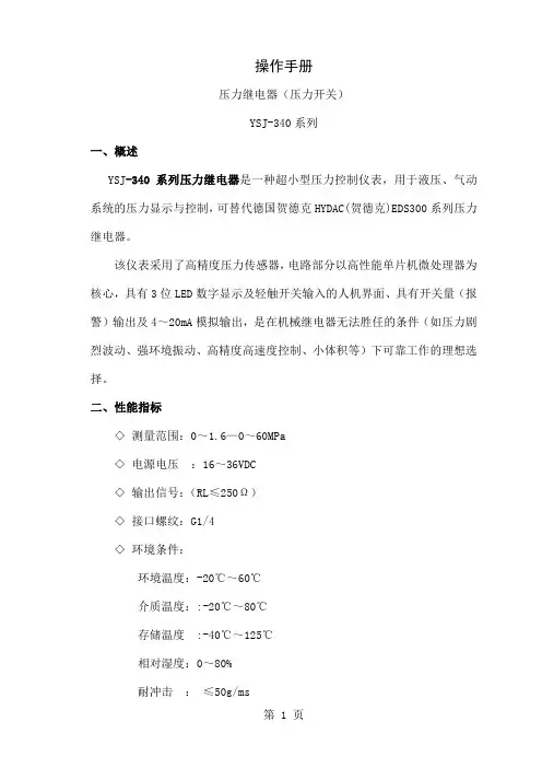
操作手册压力继电器(压力开关)YSJ-340系列一、概述YSJ-340系列压力继电器是一种超小型压力控制仪表,用于液压、气动系统的压力显示与控制,可替代德国贺德克HYDAC(贺德克)EDS300系列压力继电器。
该仪表采用了高精度压力传感器,电路部分以高性能单片机微处理器为核心,具有3位LED数字显示及轻触开关输入的人机界面、具有开关量(报警)输出及4~20mA模拟输出,是在机械继电器无法胜任的条件(如压力剧烈波动、强环境振动、高精度高速度控制、小体积等)下可靠工作的理想选择。
二、性能指标◇测量范围:0~1.6—0~60MPa◇电源电压:16~36VDC◇输出信号:(RL≤250Ω)◇接口螺纹:G1/4◇环境条件:环境温度:-20℃~60℃介质温度::-20℃~80℃存储温度:-40℃~125℃相对湿度:0~80%耐冲击:≤50g/ms耐振动:≤10g/(0~500HZ)◇输出信号精度:1.0◇过载压力:1.5%倍满量程压力◇最大功耗:≤3W触点容量:24VDC/1.2A(MAX)三、功能根据不同型号,装置可提供下列功能◇三位显示当前压力(正常工作)◇按压力、预设开关点输出开关量◇输出模拟量◇基本设定菜单◇提供四种不同输出模式:◇YSJ341带1路开关量输出(负载最大电流1.2A,无模拟量输出)◇YSJ342带2路开关量输出(负载最大电流1.2A,无模拟量输出)◇YSJ343带1路开关量输出(负载最大电流1.2A)和1路模拟量输出(4~20mA)◇YSJ344带2路开关量输出(负载最大电流1.2A)和1路模拟量输出(4~20mA)四、安装YSJ340可以通过压力管接头(DIN3852内螺纹G1/4),直接装在液压集成快上。
电气连接必须由国家认定合格的电工操作(参考中国电工国家标准规范)。
压力继电器的外壳必须同时良好的接地。
如安装在液压块里,块体通过液压系统接地时有保证的。
若用微型软管安装,客体必须单独接地。
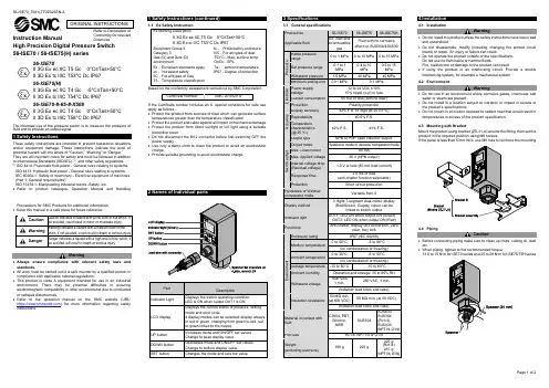
Instruction Manual56-ISE70 / 56-ISE75(H) series56-ISE70II 3G Ex ec IIC T5 Gc 0°C≤Ta≤+50°CII 3D Ex tc IIIC T53°C Dc IP6756-ISE75(H)II 3G Ex ec IIC T4 Gc -5°C≤Ta≤+50°C II 3D Ex tc IIIC T54°C Dc IP67 56-ISE70-#-65-#-X508II 3G Ex ec IIC T4 Gc 0°C≤Ta≤+50°C II 3D Ex tc IIIC T58°C Dc IP67The intended use of the pressure switch is to measure the pressure of fluid and to provide an output signal.These safety instructions are intended to prevent hazardous situations and/or equipment damage. These instructions indicate the level of potential hazard with the labels of “Caution,” “Warning” or “Danger.”They are all important notes for safety and must be followed in addition to International Standards (ISO/IEC) *1), and other safety regulations. *1)ISO 4414: Pneumatic fluid power - General rules relating to systems. ISO 4413: Hydraulic fluid power - General rules relating to systems.IEC 60204-1: Safety of machinery - Electrical equipment of machines. (Part 1: General requirements)ISO 10218-1: Manipulating industrial robots -Safety. etc.• Refer to product catalogue, Operation Manual and HandlingPrecautions for SMC Products for additional information. • Keep this manual in a safe place for future reference.CautionCaution indicates a hazard with a low level of risk which, ifnot avoided, could result in minor or moderate injury.WarningWarning indicates a hazard with a medium level of riskwhich, if not avoided, could result in death or serious injury.DangerDanger indicates a hazard with a high level of risk which, ifnot avoided, will result in death or serious injury.Warning• Always ensure compliance with relevant safety laws and standards.• All work must be carried out in a safe manner by a qualified person in compliance with applicable national regulations.• This product is class A equipment intended for use in an industrial environment. There may be potential difficulties in ensuring electromagnetic compatibility in other environments due to conducted or radiated disturbances.• Refer to the operation manual on the SMC website (URL: https:// ) for more information regarding safety instructions.1.1 Ex Safety Instruction Ex Marking DescriptionII 3G Ex ec IIC T5 Gc 0°C≤Ta≤+50°C II 3D Ex tc IIIC T53°C Dc IP67Equipment Group II Category 3Gas (G) and Dust (D) environmentEx - European standards apply ec - Increased safety IIC - For all types of GasT5 - Temperature classificationtc - Protected by enclosure IIIC - For all types of dust T53°C - Max. surface temp. Gc/Dc - EPLTa - ambient temperature IP67 - Degree of protectionBased on the conformity assessment carried out by SMC Corporation.Certificate Number:SMC 20.0029 XIf the Certificate number includes an X, special conditions for safe use apply as follows :-• Protect the product from sources of heat which can generate surface temperatures greater than the temperature classification.• Protect the product and cable against all impact or mechanical damage. • Protect the product from direct sunlight or UV light using a suitable protective cover.• Do not disconnect the M12 connector before first switching OFF the power supply.• Use only a damp cloth to clean the product to avoid an electrostatic charge.• Provide suitable grounding to avoid electrostatic charge.2 Names of Individual parts3 Specifications4 Installation4.1 InstallationWarning• Do not install the product unless the safety instructions have been read and understood.• Do not disassemble, modify (including changing the printed circuit board) or repair. An injury or failure can result.• Do not operate the product outside of the specifications. Do not use for flammable or harmful fluids.Fire, malfunction or damage to the product can result.• If using the product in an interlocking circuit: Provide a double interlocking system, for example a mechanical system. 4.2 EnvironmentWarning• Do not use in an environment where corrosive gases, chemicals, salt water or steam are present.• Do not install in a location subject to vibration or impact in excess of the product’s specifications.• Do not mount in a location exposed to radiant heat that would result in temperatures in excess of the product specification.4.3 Mounting with BracketMount the product using bracket (ZS-31-A) around the fitting, then set the product in the required position using M6 screws.If the panel is less than 5 mm thick, use M6 nuts to reinforce the mounting.4.4 PipingCaution• Before connecting piping make sure to clean up chips, cutting oil, dust etc.• When piping, tighten to the recommended torque:13.6 to 15 N•m for ISE70 series and 25 to 28 N•m for ISE75/75H series4.5 Wiring• Connections should be made with the power supply turned off.• Use a separate route for the product wiring and any power or high voltage wiring. Otherwise, malfunction may result due to noise.• If a commercially available switching power supply is used, be sure to ground the frame ground (FG) terminal. If the switching power supply is connected, switching noise will be superimposed and it will not be able to meet the product specifications. In that case, insert a noise filter such as a line noise filter/ferrite between the switching power supplies or change the switching power supply to the series power supply. • Connector mounting / removalAlign the cable connector key groove with the product connector key to insert and rotate the knurled part of the connector. M12 Connector Pin layout 56-ISE70/75(H)-##-43 No. Colour Function 1 Brown DC (+) 2 White OUT2 (PNP) 3 Blue DC (-) 4 Black OUT1 (NPN) 56-ISE70/75(H)-##-65 No. Colour Function 1 Brown DC (+) 2 White N.C. 3 Blue DC (-) 4 Black OUT1 (PNP) 56-ISE70/75(H)-##-27 / -67No. ColourFunction 1 Brown DC (+) 2 White OUT2 (NPN or PNP)3 BlueDC (-) 4 Black OUT1 (NPN or PNP)56-ISE70/75(H)-##-65-X508No. ColourFunction 1 Brown DC (+) 2 White OUT2 (4 to 20mA)3 BlueDC (-) 4 Black OUT1 (PNP)Power is supplied▼Measurement modeDetects pressure, displays values and performs switching. Other functions such as zero clear can also be set if necessary.▼ Initial settingSetting the output mode, LCD display colour, and response time.▼Pressure SettingInput of set value for pressure to perform switch output.▼Measurement mode5.1 Initial SettingPress and hold the SET button for 2 seconds or longer.The display shown right will appear to allow operating the initial setting mode.Finish initialization and return to measurement mode byno operation for 30 seconds or pressing the SET button for 2 seconds or longer.6 Pressure Setting• Pressure input mode for OUT1Press the SET button in measurement mode to display set values. [P_1] or [n_1] and the current set value will flash in turn. Press the SET button to display the next set value (Hysteresis: H_1). Press the UP or DOWN button to enter the value change mode.• When hysteresis mode is setIf the hysteresis mode is set, [H_1] and the set value of hysteresis will appear in turn after the setting for [P_1] or [n_1]. Press the SET button to return to normal measurement mode. Press the UP or DOWN button to enter the value change mode.If the hysteresis is set to 2 digits or less, the switch output may chatter if input pressure fluctuates near the set value.• When window comparator mode is setIf the Window comparator mode is set, [P_2] or [n_2] and the current set value will appear in turn after the setting for [P_1] or [n_1]. Press the SET button to display the next set value. (Hysteresis: H_1)Press the UP or DOWN button to enter the value change mode.Next, [H_1] and the set value of Hysteresis will appear in turn. Press the SET button to return to measurement mode. Press the UP or DOWN button to enter the value change mode.If the initialized value is normally open mode, [P_1] will appear, and [n_1] will appear if it is normally closed mode. The set pressure can be checked without holding or stopping switch output operation.7 Other Settings• Fine adjustment mode• Peak / Bottom value display • Key lock function • Zero Clear function .Refer to the operation manual on the SMC website (URL: https:// ) for further details of how to set these and other functions.8 Maintenance8.1 General MaintenanceCaution• Not following proper maintenance procedures could cause the product to malfunction and lead to equipment damage.• If handled improperly, compressed air can be dangerous.• Maintenance of pneumatic systems should be performed only by qualified personnel.• Before performing maintenance, turn off the power supply and be sure to cut off the supply pressure. Confirm that the air is released to atmosphere.• After installation and maintenance, apply operating pressure and power to the equipment and perform appropriate functional and leakage tests to make sure the equipment is installed correctly.• If any electrical connections are disturbed during maintenance, ensure they are reconnected correctly and safety checks are carried out as required to ensure continued compliance with applicable national regulations. How to reset the product after power cut or forcible de-energizing The setting of the product will be retained as it was before a power cut or de-energizing. The output condition is also basically recovered to that before a power cut or de-energizing, but may change depending on the operating environment.Therefore, check the safety of the whole installation before operating the product. If the installation is using accurate control, wait until the product has warmed up (approximately 20 to 30 minutes).9.1 Error Indication10 Limitations of Use10.1 Limited warranty and Disclaimer/Compliance Requirements Refer to Handling Precautions for SMC Products.11 Product DisposalThis product shall not be disposed of as municipal waste. Check your local regulations and guidelines to dispose of this product correctly, in order to reduce the impact on human health and the environment.12 ContactsRefer to or www.smc.eu for your local distributor / importer.URL : https:// (Global) https://www.smc.eu (Europe) SMC Corporation, Akihabara UDX15F, 4-14-1, Sotokanda, Chiyoda-ku, Tokyo 101 0021 Specifications are subject to change without prior notice from the manufacturer. © 2021-2022 SMC Corporation All Rights Reserved. Template DKP50047-F-085LError Error displayed Description Measures Overcurrent OUT1The load current applied to the switch output has exceeded 80 mA.Turn the power off and remove the cause of the over current. Then turn the power on. OvercurrentOUT2ResidualpressureerrorDuring zero clear operation, pressure over ±7%F.S. is applied. After 3 s, the mode will reset to the measurement mode. ±1 digit of the zeroclear range varies with individual product differences. Perform zero clear operation again after restoring the applied pressure to an atmospheric pressure condition.Pressure errorPressure has exceeded the upper limit of the set pressure range. Reset applied pressure to a levelwithin the set pressure range. Pressure has exceeded the lower limit of the set pressure range. SystemerrorDisplayed if an internal data error has occurred. Turn the power offand on again. If the failure cannot be solved, contact SMC. If the error cannot be reset after the above measures are taken, or errors other than the above are displayed, please contact SMC.。
智能压力开关使用说明一、概述CYDK102系列智能压力开关是集压力测量,显示,输出、控制于一体的智能数显压力测控产品。
该产品为全电子结构,前端采用带隔离膜充油压阻式压力传感器,输出信号由高精度,低温漂的放大器放大处理,送入高精度的A/D转换器,转换成微处理器可以处理的数字信号,经过运算处理的信号控制两路开关,对控制系统压力进行测控。
该智能数字压力开关使用灵活,操作简单,调试容易,安全可靠。
广泛应用于水电,自来水,石油,化工,机械,液压等行业,对流体介质的压力进行测量显示和控制二、特点◆4位数字显示当前压力值。
(正常应用)◆按压力预设开关点和延滞切换输出◆开关量可在零点到满度之间任意设定◆外壳设有节点动作发光二级管,便于观察◆按键调校及现场设置各种参数,操作方便.◆2路开关量输出,带载能力1.2A◆模拟量输出(4~20mA)(可选)三、技术参数四.安装4.1电气连接:1(红色)电源+2(黑色)电源-3(白):模拟输出4(兰色):开关1 5(绿色)开关24.2壳体结构:控制范围-0.1…0~0.01…100MPa 控制精度≤±0.5%FS稳定性≤±0.5% /年显示精度±0.1%FS显示方式4位0.36"数码管2个LED灯显示范围-1999~9999 电源范围24V±20% 电源影响≤±0.1%FS最大功耗< 3W 引线方式M12工业连接器输出模式两路开关量+一路模拟量负载容量<24V1.2A防护等级IP65 开关寿命>1000000次环境温度-25℃~70℃介质温度-25℃~85℃存储温度-25℃~85℃相对湿度0~80%五、设置功能总述5.1.面板及按键5.2输出功能:5.2.1开关量输出QYK102有两路开关量输出。
每路开关量输出可以设定1个压力开关点和一个开启延时值。
相应的输出会在开关点的吸合值到达时切换并在压力下降到低于释放值时回复。

■MODEL NUMBER DESIGNATIONP S 6 0 - 1 0 2 R - N M C NSeries name Signal / power cable pullout methodPressure portSwitch output interfaceRated pressure rangePressure reference102:−100 ~ 100 kPa 103:−100 ~ 1000 kPa302:−100 ~ 300 kPaR :Compound pressure (Negative pressure ~ Positive pressure)CN :Connector pulloutM :M5 female screwN :NPN open collector P :PNP open collectorPRESSURE SWITCHES WITH GAUGEPS60● Applicable for negative through positive pressure with 10 mm thick slim housing● Suitable for use in clean rooms with easy-to-use push keys ● Plug-in connector is provided for eas y ins tallation and maintenance● Space saving and mountable on DIN rails ● Data protection by panel lock system ● Low consumption by nondisplay mode■FEATURES■LIST OF MODEL NUMBERS※Verify the above model numbers when placing orders.PS60PRESSURE SWITCHES WITH GAUGE■STANDARD SPECIFICATIONS● Unless otherwise specified, the specs are defined at an ambient temperature of 25 ± 5 °C and excitation voltage of 24 V DC.PS60PRESSURE SWITCHES WITH GAUGE■CIRCUIT DIAGRAMSBB● NPN open collector● PNP open collector■SWITCH OUTPUT MODE■DISPLAY RANGENote 1. In the Separate Mode, setting 1 corresponds to SW1, andSetting 2 corresponds to SW2.Note 2. In the Window Comparator Mode, the minimum value forSW1 and SW2 corresponds to Setting 1 and the maximum value corresponds to Setting 2.※Atmospheric pressure● Display range can be selected as the table.Note) “–” on the table indicates that it is not selectable in relation to resolution and display lines.※ : In terms of setting display range, please verify the default mode.■ENVIRONMENTAL CHARACTERISTICS■OUTLINE DIMENTIONSUnless otherwise specified, tolerance : ± 0.5 (Unit: mm)PS60PRESSURE SWITCHES WITH GAUGE● Pressure port M type (NMCN, PMCN)■Accessories● DIN rail adapterDIN base : PBTSlide (DIN stopper) : POM。

P2系列双显数字压力开关使用说明书一、主要特点:1、开放式仪表参数设定2、采用防水结构,外形美观、安装方便;3、设定参数密码锁定,断电后永久保存。
4、同时显示动作点压力值(SV)与当前压力值(PV)二、技术参数·压力范围:0~0.5Kpa…50Mpa·控制精度:±1字·过载能力:1.5倍·动作时间:不超过1ms·使用环境:环境温度 0~50℃相对湿度≤85%RH避免强腐蚀气体·测量精度:0.5%FS ±1字·分 辨 率:1、0.1、0.01字·工作电压:DC24V·功 耗:≤5W·显示方式:-199~999测量值显示-199~999设定值显示·结 构:铝盒密封安装,防水·螺纹接口:M20 x 1.5·控制方式:两路开关量输出,可设置动作点、上/下限动作、回差/带差继电器控制模块(用户可选):0.3A at 220VAC;2A at 30VDC 三极管控制模块(用户可选):1.5A at 30VDC双向可控硅制模块(用户可选):5A at 250VAC·参数设定:面板轻触式按键数字设定,参数设定后永久保存。
参数设定值密码锁定 ·保护方式:继电器输出状态LED指示电源欠压自动复位工作异常自动复位(Watch Dog)三、操作方式1、正确的接线请参照仪表随机接线图(见附录)接妥输入、输出信号线及电源线,并请确认无误。
2、仪表的上电本仪表无电源开关,接入电源即进入工作状态。
四、控制参数设定 (一)、仪表面板项 目 功 能PV 显示测量值 显示实时测量值 显示AL1动作值与AL2动作值显 示 器 SV 显示动作点在参数设定状态下,显示参数符号或设定值按压然后抬起按下不放保持5秒 SET 参数设定键1) 在显示模拟量输出值时则进入一级参数设定,显示参数CLK 符号。
文件No.PS※※-OMU0008CN-D数字式压力开关ZSE20C(F)ISE20C(H)安全注意事项 2型式表示・型号体系 9产品各部分名称及功能 11用语说明 12安装·设置 16设置方法 16配管方法 19配线方法 21设定概要[测试模式] 24压力的设定 25 3步设定模式 26简单设定模式 28功能选择模式 30功能选择模式 30出厂时的设定 30 F0 单位切换功能 32 F1 OUT1的设定 33 F2 OUT2的设定 36 F3 数字滤波器的设定 38 F4 自动预设功能的设定 39 F5 FUNC端子的设定 41 F6 显示值微调的设定 43 F10 子画面的设定 44 F11 显示分辨率的设定 50 F80 省电模式的设定 51 F81 密码输入的设定 52 F82 线名输入的设定 54 F90 全功能的设定 55 F96 输入信号确认 57 F97 复制功能的选择 58 F98 输出确认 60 F99 恢复出厂设置 62其他设定 63维护 67忘记密码的场合 67故障一览表 68规格 77规格表 77外形尺寸图 79安全注意事项此处所示的注意事项是为了确保您能安全正确地使用本产品,预先防止对您和他人造成危害和伤害而制定的。
这些注意事项,按照危害和损伤的大小及紧急程度分为“注意”“警告”“危险”三个等级。
无论哪个等级都是与安全相关的重要内容,所以除了遵守国际标准(ISO/IEC)、日本工业标准(JIS)*1) 以及其他安全法规*2)外,这些内容也请务必遵守。
*1) ISO 4414: Pneumatic fluid power -- General rules relating to systemsISO 4413: Hydraulic fluid power -- General rules relating to systemsIEC 60204-1: Safety of machinery -- Electrical equipment of machines (Part 1: General requirements)ISO 10218: Manipulating industrial robots-SafetyJIS B 8370: 空气压系统通则JIS B 8361: 油压系统通则JIS B 9960-1: 机械类的安全性‐机械的电气装置(第1部: 一般要求事项)JIS B 8433: 产业用操作机器人-安全性等*2) 劳动安全卫生法 等安全注意事项本产品适用于下述“保证以及免责事项”、“适合用途的条件”。
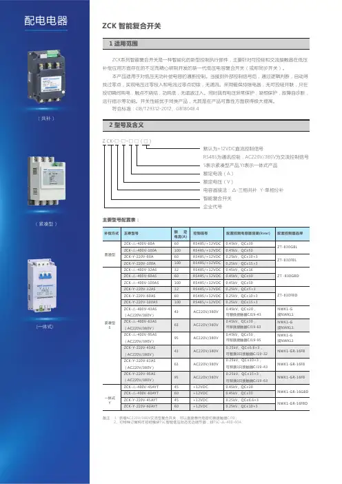
ZCK 智能复合开关Z CK系列智能复合开关是一种智能化的新型控制执行部件,主要针对可控硅和交流接触器在低压补偿应用方面存在的不足而精心研制开发的新一代低压电容复合开关(或称同步开关)。
本产品适用于对低压无功补偿电容的通断控制。
当接到外部控制信号后,通过逻辑判断,自动寻找过零点,实现电压过零投入和电流过零点切除,无涌流。
采用磁保持继电器,无可控硅并联,只在投切瞬间耗电,触点不烧结,功耗低,无谐波注入。
同时具有电压异常保护,缺相保护,故障自诊断,运行指示等功能。
开关性能优于同类产品,尤其是在产品可靠性方面获得极大提高。
符合标准:GB/T29312-2012、GB 18048.4Z C K -□-□-□□(□)默认为+12VDC直流控制信号RS485为通讯控制,AC220V/380V为交流控制信号S表示紧凑型产品, Y t表示一体式产品额定电流(A)额定电压(V)电容器接法:△-三相共补Y-单相分补智能复合开关企业代号主要型号配置表:备注: 1、新增AC220V/380V交流型复合开关,可以直接替代电容切换接触器CJ19;2、可特殊订做纯可控硅模块TSC智能低压动态无功调节器,如TSC--400-60A△电力电子及其它电器类正泰-智慧能源解决方案提供商 l 674 3.1 额定工作电压:共补380VAC±20%/分补220VAC±20%3.2 控制电容容量:三相≤50kvar,△型接法;单相≤15kvar,Y型接法3.3 额定电流:100A、60A、32A3.4 投入涌流倍数:≤3.0Ic3.5 功耗:<1.5W3.6 开关使用寿命:>20万次3.7 接触压降:≤100mV3.8 开关耐压:≥2500V3.9 动作响应时间:≤100mS3.10 每次接通与关断间隔:≥1S3.11 连续两次接通间隔时间:普通型≥120S,紧凑型≥0.5S,一体式≥5S4.1 过零投切:智能复合开关的基本工作原理是通过过零检测与逻辑判断,实现电压过零导通和电流过零切断。
![智能型数显压力开关使用说明书-A4[整理]](https://uimg.taocdn.com/431d7764f342336c1eb91a37f111f18583d00c1d.webp)
六、指示灯定义及工作状态说明电源指示灯接通电源后常亮上限指示灯进行上限设置过程时长亮,在运行状态中,当压力高于上限,上限指示灯长亮。
下限指示灯进行下限设置过程时长亮;在运行状态中,当压力低于下限,下限指示灯长亮。
单位指示灯默认单位为MPa,MPa、Kg/cm2、PSI可任意切换。
运行指示灯闪烁控制器处于运行状态中,继电器处于闭合状态。
常亮控制器处于运行状态中,继电器处于断开状态。
不亮控制器处于设置状态,继电器处于断开状态。
七、显示代码说明字符字符定义E--E 表示传感器损坏或电线连接不正确。
E--1 表示控制器在工作状态下,持续3分钟压力未变化,按任意键返回运行状态。
E--2 当前压力超过(上限+0.1MPa),按任意键返回运行状态。
C--L 表示正在清零操作。
E--H 超过压力控制器的最大量程。
8888数据设置存储成功标志。
八、注意事项1.收到产品后,请检查包装及外形是否完好,并核对型号和规格是否与您选购的产品相符。
2.按产品所提供的过程连接、电气连接和安装方式,将产品正确可靠安装并接线。
3.请勿带电安装!4.使用过程中请注意产品的技术规范和使用条件,如允许的介质温度、过载压力、供电电压等。
5.压力开关属于精密器件,用户在使用时请不要自行拆卸,更不能用硬物触碰膜片,以免造成产品的损坏。
6.在安装过程中,注意保护产品,不得强力安装或者拆卸,否则容易损坏产品,特别是安装螺纹。
7.安装时请用合适的扳手安装或拆卸,不得强行用手拧动壳体来拧紧或者拆卸,否则造成的损害不在保修的范围内。
8.安装后通电测试,出现非正常现象,除非具备产品调节设备和技能,否则请将产品联系我公司的售后技术人员。
智能型数显压力开关Intelligent digital pressure switch智能型数显压力开关是集压力的测量、显示、控制于一体的智能化控制仪表,具有操作简单、价格便宜、抗震动、控制精度高、使用寿命长等特点。
该压力开关具有延时控制功能、三种显示单位可以任意切换、误差一键清零等多种功能。
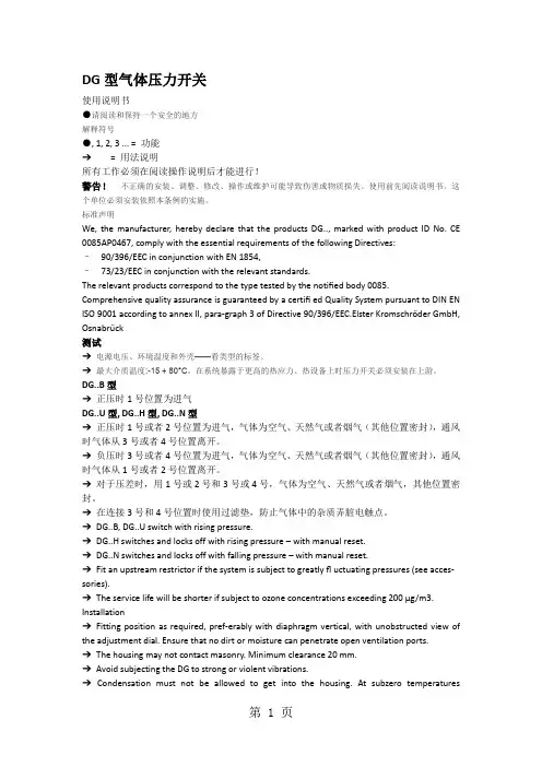
DG型气体压力开关使用说明书●请阅读和保持一个安全的地方解释符号●, 1, 2, 3 ... = 功能➔= 用法说明所有工作必须在阅读操作说明后才能进行!警告!不正确的安装、调整、修改、操作或维护可能导致伤害或物质损失。
使用前先阅读说明书。
这个单位必须安装依照本条例的实施。
标准声明We, the manufacturer, hereby declare that the products DG.., marked with product ID No. CE 0085AP0467, comply with the essential requirements of the following Directives:–90/396/EEC in conjunction with EN 1854,–73/23/EEC in conjunction with the relevant standards.The relevant products correspond to the type tested by the notified body 0085. Comprehensive quality assurance is guaranteed by a certifi ed Quality System pursuant to DIN EN ISO 9001 according to annex II, para-graph 3 of Directive 90/396/EEC.Elster Kromschröder GmbH, Osnabrück测试➔电源电压、环境温度和外壳——看类型的标签。
➔最大介质温度:-15 + 80°C。
在系统暴露于更高的热应力、热设备上时压力开关必须安装在上游。
DG..B型➔正压时1号位置为进气DG..U型, DG..H型, DG..N型➔正压时1号或者2号位置为进气,气体为空气、天然气或者烟气(其他位置密封),通风时气体从3号或者4号位置离开。
机械式压力开关型号:MD-S700量程:0-25Bar设定压力:10Bar产品材质:不锈钢量程:ZG1/4出厂日期:检验人员:在使用本压力开关之前必须详细阅读此压力开关的有关资料和操作说明。
该系列压力开关为机械式压力开关,当流体压力作用在感压力元器件,使之产生形变,将向上移动,通过栏杆弹簧等机械结构,最终启动最上端的微动开关,使电信号输出。
该系列压力开关内部采用全不锈钢感压膜片,它的特点是使用方便,工作稳定,机械寿命长。
用户可通过随产品的附件工具设置控制点,或者是出厂时要求我厂预设好压力控制点。
该系列产品应用广泛,特别适合自动化设备配套,矿山机械等应用机械的压力控制及保护。
一.产品参数产品量程0~0.2...1230Bar (根据客户选择不同,量程有差异)设定压力0~0.2...600Bar (根据产品的量程不同,设定范围有差异)测量介质水、油、气体等对不锈钢无腐蚀的流体电气触点镀银设定延时膜片式约为10% 活塞式约为15%最高行程90次/秒工作温度-20℃~80℃机械寿命106 次认证方式CE认证重量60g电气特性可变式开关逻辑:常开和常闭电源保护:根据DIN 40050标准电源连接:根据DIN 43650标准接线保护反极性和短路保护安装接口G1/4 G1/2 或用户定制材质不锈钢二.连线方法端子 定义最大载荷红色 报警公共端(COM 端) DC42V1A DC125V0.2AAC42V3A AC125V3A黑色 报警常开端(NO 端) 蓝色报警常闭端(NC 端)连线前必须确定使用电路中的电流电压是否超过压力开关的额定载荷! 连线时,必须切断电源以免造成人身伤害和产品的损坏!三.尺寸图及电气连接图*因防爆等级及客户要求不同,外形有差异。
四.注意事项1.不得施加超过产品额定承载的压力!2.不得通过超过产品额定承载的电流及电压!3.不得测量对不锈钢或铜有腐蚀的介质!4.不得带电连线或调节压力设定点!5.强烈的碰撞可能会影响设定值,甚至会损坏产品。
目录1 说明§1.1 重要说明§1.2 开关标识2 探测头安装§2.1 压力与真空探测头§2.2 差压探测头§2.3 温度探测头3 封装外壳的安装§3.1 “C”型外壳§3.2 “Z”型外壳§3.3 “V”型和“W”型外壳§3.4 “M”型外壳4 电气安装5 设定点调节6欧共体标准符合说明1 说明§1.1 重要说明* BETA压力开关属于精密仪器请正确放置或搬动。
BETA压力开关在达到设定点的(差压)压力或者温度时开关动作。
* 在按照说明书指示正确安装,该开关的设计与结构是完全免维护的。
切莫采用液态油或油脂润滑开关的任何部件。
* 除了更换外壳密封与安装支架外,不要移动或更换本开关的任何部件。
* 避免暴露在超高温、超低温、有侵蚀性环境中,-30~80℃为适宜温度。
* 调节螺丝有自锁性,所以在调节设定点后禁止封死调节螺丝。
* 安装前请详细检查铭牌上数据。
* 所有尺寸均以mm毫米标注。
* 如果您需要帮助请与供应商联系,开关只有在去污清洗后才能进行维护检修。
* 如果您需要额外的膜片O形圈和微动开关,请给出序列号向供应商购买。
* 开关的检修维护请由专业的仪表工程师实施。
除了更换膜片O形圈和微动开关以外,其它形式的检修维护有厂方执行。
* 非厂方检修维护的操作会影响产品本身的质量保证。
* 本章节的指导说明书的步骤也是安装步骤说明。
* 地基与工程环境的强烈振动可能会影响开关的正常功能。
§1.2 开关标识压力开关的铭牌上面标明了规格型号,4到7步可以确定该压力开关的设计组成,后缀的X+数字来表明特殊要求,该特殊要求可参照数据书。
外壳封装C1-P304L-S1N-B1-K1-Y-X2第一个字符即第一步标明了外壳封装形式:C、V、W、Z或M,参照图1-4和15。
探测头C1-P304L-S1N-B1-K1-Y-X2第一个和最后一个字符构成第二步标明了探测头规格及功能,参照图5-12和表1。