Chemical Bonding in Group III Nitrides
- 格式:pdf
- 大小:121.82 KB
- 文档页数:8

化工进展Chemical Industry and Engineering Progress2023 年第 42 卷第 12 期含氮有机液体储放氢催化体系研究进展李佳豪1,杨锦2,潘伦1,钟勇斌2,王志敏2,王锦生2,张香文1,邹吉军1(1 天津大学化工学院,绿色合成与转化教育部重点实验室,天津 300072;2 东方电气集团东方锅炉股份有限公司,四川 成都 610000)摘要:氢能源作为重要的二次能源,能量密度大、环境友好且用途广泛,是人类战略能源发展的重要方向。
然而,氢气储运仍面临较大的成本和安全难题,有机液体储氢化合物(LOHCs )储放氢技术以其储氢密度较高、储存条件温和、运输方便等优势成为氢气储运可供选择的技术之一。
相比稠环芳烃类化合物,含氮有机储氢化合物具有更温和的催化加氢和脱氢条件,可有效提高储放氢鲁棒性和反应能效。
基于此,本文系统综述了含氮有机储氢化合物加氢及脱氢反应研究进展,阐述了两类反应的路径和催化作用机制,从催化剂活性中心和载体、双金属协同效应、反应条件、催化剂稳定性等方面系统分析了加氢/脱氢催化剂,并详细总结了基于连串反应、反应网络等模型的反应动力学。
介绍了含氮有机储氢化合物储氢技术目前面临的挑战并提出未来的研究思路及展望。
但是该技术仍存在较多问题,应在有机储氢化合物配方体系、储放氢连续反应系统、催化剂设计与制备、催化剂构效关系、精准反应动力学和全面理化性质数据库等方面进行深入研究。
关键词:氢;含氮有机液体储氢化合物;反应机理;催化剂;反应动力学中图分类号:TK91 文献标志码:A 文章编号:1000-6613(2023)12-6325-20Research progress in catalytic system for hydrogen storage and releasefrom nitrogen-containing liquid organic carriersLI Jiahao 1,YANG Jin 2,PAN Lun 1,ZHONG Yongbin 2,WANG Zhimin 2,WANG Jinsheng 2,ZHANG Xiangwen 1,ZOU Jijun 1(1 Key Laboratory for Green Chemical Technology of the Ministry of Education, School of Chemical Engineering andTechnology, Tianjin University, Tianjin 300072, China; 2 DongFang Boiler Group Co., Ltd., Chengdu 610000, Sichuan, China)Abstract: As an important secondary energy, hydrogen is of high energy density, environmental friendliness and wide use, which is an important direction of human strategic energy development. However,hydrogen storage and transportation are still facing problems of high cost and safety. The hydrogen storage and release technology based on liquid organic hydrogen carriers (LOHCs) has become one of the available technologies with its advantages of relatively high hydrogen storage density, mild storage conditions and convenient transportation. Compared with polycyclic aromatic hydrocarbons, nitrogen-containing LOHCs is milder in catalytic hydrogenation and dehydrogenation, which can effectively improve the robustness of hydrogen storage and release and the reaction efficiency. Based on this, this paper systematically reviewed综述与专论DOI :10.16085/j.issn.1000-6613.2023-0089收稿日期:2023-01-19;修改稿日期:2023-04-11。

CERAMICSINTERNATIONALAvailable online at Ceramics International 40(2014)2047–2056Chemically modi fied boron nitride-epoxy terminated dimethylsiloxanecomposite for improving the thermal conductivityKiho Kim,Myeongjin Kim,Yongseon Hwang,Jooheon Kim nSchool of Chemical Engineering &Materials Science,Chung-Ang University,Seoul 156-756,KoreaReceived 30May 2013;received in revised form 22July 2013;accepted 24July 2013Available online 21August 2013AbstractThe thermal conductivities of composites with an epoxy-terminated dimethylsiloxane (ETDS)matrix and boron nitride (BN)powder fillers were investigated.Two surface curing agents,3-glycidoxypropyltrimethoxysilane (KBM-403)and 3-chloropropyltrimethoxysilane (KBM-703),were doped onto the surfaces of hydroxyl-functionalized boron nitride using a simple sol –gel process to act as fillers in the thermally conducting composites.These synthesized materials were embedded in epoxy resin via a solvent casting method.The surface modi fication had an appreciable effect on the thermal conductivity resulting in increased thermal conductivity up to 70wt%.The thermal conductivities of the composites containing 70wt%BN particles treated with the KBM-403and KBM-703curing agents were 4.11and 3.88W/mK,respectively,compared to 2.92W/mK for the composite without surface treatment.&2013Elsevier Ltd and Techna Group S.r.l.All rights reserved.Keywords:posites;C.Thermal conductivity;D.Nitrides;Surface treatment1.IntroductionDemands for the miniaturization and continuous perfor-mance improvements of electronic packages have led to the development of new microelectronic packaging techniques.The typical characteristics of future microelectronic packaging include high density,high frequency,and high speed [1–3].It is well known that the reliability of an electronic device is exponentially dependent on the operating temperature of the junction,whereby a small difference of the operation tempera-ture can result in a two-fold reduction of the lifespan of a device [4].Improvements of size and performance are likely to result in the generation of a greater amount of heat in a smaller volume of space.To ensure proper device operation,the unwanted heat must be removed as quickly and effectively as possible to maintain the operation temperature,suggesting that the packaging materials of the product needs to have good thermal conductivity [5,6].Epoxy resin has been widely applied in electronics,paints,electrical insulators,printed circuit boards,and packaging materials as a matrix [7,8].Unfortunately,epoxy used alone as an electronic packaging material cannot effectively dissipate the heat generated from high packing and power-density devices,given the relatively low thermal conductivity range of epoxy of 0.1–0.3W/mK.Several studies have been conducted to improve the thermal conductivity of epoxy.For example,polymers filled with thermally conductive fillers are emerging as a cost-effective means of coping with thermal management issues.Many researchers have investigated the thermal conductivity enhancement of composite materials including oxides (Al 2O 3,SiO 2,ZnO)[9–11],carbide (SiC)[12],and nitrides (AlN,BN,Si 3N 4)[13,14].The properties of these epoxy/inorganic filler composites depend on the nature of the inorganic filler including their chemical and physical composition,size,shape and dispersion in the epoxy matrix.Thermally conductive fillers,like those mentioned above,have attracted attention due to their high thermal and low electrical conductivities,while metallic particles have high thermal and electrical conductiv-ities.Among the fillers,boron nitride has been considered as/locate/ceramint0272-8842/$-see front matter &2013Elsevier Ltd and Techna Group S.r.l.All rights reserved./10.1016/j.ceramint.2013.07.117nCorresponding author.Tel.:þ8228205763.E-mail address:jooheonkim@cau.ac.kr (J.Kim).an attractive candidate due to its significantly high thermal conductivity($300W/mK),lack of toxicity,superior chemi-cal stability,electrical insulation properties,and relatively low cost.In order to obtain a higher thermal conductivity while maintaining the existing properties,filler loadings of60wt% or higher have traditionally been incorporated to form a heat conduction path in the matrix that is as continuous as possible. However,a highfiller content becomes rather inflexible with voids and cracks forming betweenfillers.Moreover,the BN/ epoxy slurry has a relatively low viscosity before drying, which facilitates the sedimentation of the BNfiller.As a result, BNfillers settle to the bottom of the compositefilm,the heat-conductive path is cut off,and the thermal conductivity decreases.In response to this issue,many studies have suggested fabrication of a surface-modified BN particle to preventfiller sedimentation[15,16].Recently,BN has been coated with a surface-curing agent to further enhance the thermal conductivity of polymer compo-sites,resulting in a reduction of sedimentation due to the lone-pair electron interaction of particle surfaces into the matrix.Gu et al.achieved a thermal conductivity of1.052W/mK using a hot disk instrument for epoxyfilled with silane-modified BN at a solid loading of60wt%[17].Yung et al.reported the effect of multi-modal particle size mixing on the formation of a thermally conductive network[18].Unfortunately,these previous experiments used nano-scale BN particles($1μm). Due to the small size of thefiller-containedfilm,heat passing through the boundary of the particles is more frequently the main cause of the phonon scattering.The diffuse boundary scattering due to the short wavelength in comparison to interface roughness of dominant phonon heat carriers not only reduces the phonon mean free path,but can also destroy the coherence of the phonons[19].Thermal resistance at particle junctions known as thermal boundary resistance or Kapitza resistance is one of the primary causes of heat transfer property reduction.In the presence of a heatflux across the boundary,this thermal resistance causes a temperature dis-continuity at the boundary.Due to the differences of the electronic and vibrational properties of various materials,an energy carrier will scatter when attempting to traverse the interface[20–22].It is known that hexagonal BN particles have a plate-like shape withflat surfaces corresponding to the basal planes of the hexagonal crystal structure.The basal plane of BN is molecularly smooth and has no surface functional groups available for chemical bonding or interactions.In contrast,the edge planes of the platelets have functional groups such as hydroxyl and amino groups.These functional groups allow the BNfiller to disperse in an organic solvent and chemically bond with other rge BN particles are significantly decreased in the edge plane areas,resulting in difficulty obtaining uniform dispersion and chemical bonding.To this end,Sato et al.employed0.7μm BN particles as a thermal conductivefiller on polyimide resin[23,24].For the effective use of micro-scale BN as afiller,another surface treatment is necessary to make the reaction site of the particle surface.In this study,a polymer matrix,dimethyl siloxane-basedepoxy,was employed to fabricate a thermally conductivecomposite and a12μm BN particle was adopted as acompositefiller to reduce phonon scattering and improve thethermal conductivity.To increase the affinity and dispersibilityof thefiller in the epoxy matrix,which is expected to provide agood thermal conductivity,two types of surface curing agentswere employed.The resulting surface curing agent-coated BNpossessed electrical insulating properties in addition toenhanced thermal conductivity due to reduced thermal resis-tance at the junction.The mechanical properties of thefabricated composites were measured and the data demon-strates that a small amount of surface curing agent enhancesthe thermal and mechanical properties.2.Experimental2.1.Synthesis of ETDSThe epoxy-terminated dimethysiloxane(ETDS)oligomerwas obtained from Shin-Etsu silicon(KF-105,equivalentweight(E.E.W)=490g/eq,density=0.99g/cm3).In ourprevious study,the weight ratio of the epoxy to the curingagent was determined to provide efficientflexibility of thematrix.In this study,the equivalent weight ratio of ETDS toDDM(4.4′-diamino diphenylmethane)was1:2.1.9g of DDMwas placed in a four-neck roundflask equipped with a refluxcondenser and was preheated to363K.9.5g of the ETDSresin was added and heated in an oil bath at363K for1hunder a N2atmosphere.The bubbles in the mixture wereremoved by placing the mixture in a vacuum oven for30minat room temperature.The mixture was then placed in an oilbath at323K for10min in a N2atmosphere.Thefinaldegassing was performed in a vacuum oven for1h at roomtemperature to remove air bubbles[25].2.2.Surface modification of BNThe detailed synthesis procedure is shown in Fig.1.First,micro-BN particles were suspended in a5M sodium hydro-xide solution at1101C for18h to attach more hydroxide ionsonto the surfaces.Because micro-BN particles have fewfunctional groups,surface treatment is necessary to facilitatechemical bonding with the surface curing agent.After basesolution dipping,the particles were rinsed with D.I.water and filtered several times to adjust the pH from basic to neutral. The micro-BN hydroxide particles were left in the furnace at801C for5h,cooled to room temperature,and then stored indesiccators.The BN particles were modified with two surface curingagents,KBM-403and KBM-703,obtained from Shin-EtsuSilicon by a sol-gel reaction.An appropriate amount of3-glycidoxypropyltrimethoxysilane(KBM-403;3–5%based onthe weight of the micro-BN particles)and3-chlorop-ropyltrimethoxysilane(KBM-703)were added to D.I.waterand stirred at501C for30min to achieve hydrolysis.Themicro-BN hydroxide particles were then dipped into theK.Kim et al./Ceramics International40(2014)2047–2056 2048resulting solution and stirred at 701C for 1h,followed by rinsing with D.I.water and filtering three times.The particles were then vacuum dried at 801C for 5h to remove the solvent.The amount of the coating solution necessary is preferably 0.05–10%by weight,based on the weight of the particles.When the amount of the coating solution is less than 0.05%by weight,there is a tendency for insuf ficient and non-uniform particle coating to occur.When the amount of the coating solution exceeds 10%by weight,the obtained particles may possess excessive thermal resistance,thereby causing a decrease of the thermal conductivity of the composite films [26].2.3.Preparation of the BN/epoxy compositesThe composites were prepared by solution blending and a casting method consisting of (a)adding surface curing agent-coated micro-BN to the ETDS epoxy resin (50,60,70wt%)for approximately 3h in N,N-dimethylformamide (DMF)until the synthesized materials were completely mixed,(b)fabricat-ing the composite films to a uniform thickness via a doctor blade on the Te flon mold,(c)pre-curing the films at 1501C for 3h until no air bubbles appeared on the surface followed by post-curing at 1801C for 5h,and (d)cooling to room temperature.2.4.CharacterizationFourier transform infrared (FT-IR;Parkin-Elmer Spectrum One)spectroscopy and X-ray photoelectron spectroscopy (XPS;VG-Microtech,ESCA2000)were employed to analyze the surface curing agent-coated BN.For FT-IR spectroscopy,the ATR mode was used to avoid the in fluences of moisture adsorbed on the potassium bromide (KBr)particles and the scans were performed using radiation in the frequency range of 400–4000cm À1.In the XPS analysis,a monochromatic Mg K αX-ray source was used at 1253.6eV and the Gaussian peak widths obtained by curve fitting were constant in each spectrum.Thermogravimetric analysis (TGA;TGA-2050,TAinstrument)of the samples was carried out to examine the thermal degradation of BN,BN-403,and BN-703.4mg of the samples were heated to 8001C at a heating rate of 101C/min under a nitrogen atmosphere.Field emission scanning electron microscopy (FE-SEM;Sigma,Carl Zeiss)was carried out to con firm the cross-sections of the component films before and after the silane treatment.The samples were sputtered with a thin layer of platinum to avoid the accumulation of charge before the FE-SEM observations.The thermal diffusivity (δ,mm 2s À1)at room temperature was measured on disk samples using a laser flash method (Netzsch Instruments Co.,Nano flash LFA 447System).The speci fic heat (C ,J g À1K À1)at room temperature was measured on disk samples via differential scanning calorimetry (DSC;Perkin-Elmer Co.,DSC-7System)and the bulk density (ρcomp ,g cm À3)of the specimens was measured using the water displacement method.The thermal conductivity (Ф,W mK À1)was calcu-lated using the following equation:Ф¼δC ρcompTo study the mechanical properties of the composite materials,mechanical analysis (DMA;Triton Instrument,Triton DMTA)was carried out.The storage modulus of the solid films was measured at a frequency of 1Hz.The temperature range was À180to 1801C with cooling and heating rates of 101C/min.3.Results and discussion3.1.Structure analysisThe chemical structures of the surface-modi fied BN were determined using Fourier transform infrared spectroscopy (FT-IR),thermogravimetric analysis (TGA),and X-ray photo-electron spectroscopy (XPS).Fig.2(a –c)shows the FT-IR spectra of pristine BN,BN-403,and BN-703,respectively.For pristine BN,the bands at 1400and 800cm À1indicate stretching vibration in the hexagonal BN.The absorption band of pristine BN at 2300–2380cm À1represents absorbed CO 2.Fig.1.Reaction scheme for the preparation of surface curing agent treated BN particle (BN-403,BN-703).K.Kim et al./Ceramics International 40(2014)2047–20562049Comparing the pristine BN and the surface curing agent-treated BN (BN-403and BN-703),the new band at 1100cm À1corresponds to stretching of the Si –O bonds,which existed in the pure surface curing agent.Detailed surface information of pristine BN,BN –OH,BN-403,and BN-703was collected by X-ray photoelectron spectroscopy (XPS)and the corresponding results are pre-sented in Fig.3.In the spectrum of pristine BN,there are only two elements of B and N.However,the O 1s signal emerges in the spectrum of BN –OH.This result implies that the hydroxyl groups were effectively introduced on the BN surfaces and edges via the sodium hydroxide treatment.These hydroxyl groups,acting as anchor sites,enabled attachment between the BN particles and surface curing agent.Moreover,the new peaks of C 1s and Si 2p can be assigned in the spectra of both BN-403and BN-703,indicating that both surface curing agents,403and 703,were successfully attached to the surface and edges of pristine BN particles.The detailed chemical bonding of fabricated,surface-treated BN particles was con firmed from the de-convoluted B 1s,Si 2p,and C 1s spectra,the results of which are shown in Fig.4.Fig.4(a and b)show the de-convoluted B 1s spectra of BN-403and BN-703,respectively.The B 1s spectra of both BN-403and BN-703showed a strong binding energy peak for the B –N bond and a weak binding energy peak for the B –OH bond at 190.4eV and 192eV,respectively [27,28].The B –OH peak resulted from the introduction of a hydroxyl group by the base treatment.In order to provide clearer evidence of chemical bonding between the BN particles and the silane curing agent,the Si 2p peak of these synthesized materials can be fitted by a curve with several component peaks.Fig.4(c and d)shows the de-convoluted Si 2p spectra of BN-403and BN-703,respectively.In the spectra of both BN-403and BN-703,the strong peak at the binding energy of 102.1eV represents the bond between silicon and oxygen originating from the BN particles (B –O –Si),indicating that the surface curing agent and BN particles are connected through the hydroxyl groups.The peak at 103.3eV is attributed to siloxane (Si –O –Si)resulting from the partial hydrolysis of the silane curing agent molecules during the silanization reaction.Moreover,the peak at 100.8eV is attributed to Si –C bonding in the silane curing agent molecules.These results are in agreement with the reaction mechanism of silane,including the hydrolysis of –OCH 3,condensation to oligomers,hydrogen bonds between oligomer and hydroxyl groups on the substrate,and the formation of the covalent linkage between silane and the substrate.The peak at 102.5eV is attributed to Si –OH bonding,indicating that some hydroxyl groups did not hydro-lyze and a small amount of hydroxyl group remained [29,30].This implies that the amount of hydroxyl groups on the BN surface was not suf ficient to make a uniform siloxane network and some hydroxyl groups in the surface curing agent were not hydrolyzed.This is due to the basal plane of the boron nitride particle surface having no functional groups.In addition,the silane coupling agent does not coat the surface uniformly such that the hydroxyl groups of the surface curing agent remained.The C 1s spectra of both BN-403and BN-703were de-convoluted to compare the structural differences of the two silane curing agents and the results are shown in Fig.4(e and f),respectively.In the spectra of both BN-403and BN-703,the strong peak at a binding energy of 284.7eV indicates the C –C bond and the weak peak at the binding energy of 283.44eV represents the C –Si bond,which exists in the surface curing agent structure.The primary difference between KBM-403and KBM-703is that KBM-403has ether and epoxide groups,whereas KBM-703has a chloride atom at the end of the carbon chain.In the C 1s spectrum of BN-403,C –O bonding is observed at a binding energy of 286.2eV,which originates from the ether and epoxide groups.However,in the case of BN-703,the peak at 285.9eV is attributed to C –Cl bonding,which can be explained by the existence of a chloride atom at the end of the carbon chain [31].Based on these results,it can be concluded that the silane treatment can effectively introduce the surface curing agent onto the surface ofBN.Fig.2.FT-IR spectra of (a)raw BN,(b)BN-403and (c)BN-703.Fig.3.X-ray photoelectron spectroscopy survey scans of (1)raw BN,(b)BN-OH,(c)BN-403,and (d)BN-703.K.Kim et al./Ceramics International 40(2014)2047–20562050Fig.4.XPS spectra of BN-403and BN-703.(a)XPS B 1s spectrum of BN-403:(b)XPS B 1s spectrum of BN-703:(c)XPS Si 2p spectrum of BN-403:(d)XPS Si 2p spectrum of BN-703;(e)XPS C 1s spectrum of BN-403:(f)XPS C 1s spectrum of BN-703.K.Kim et al./Ceramics International 40(2014)2047–20562051The compositions of the as-prepared BN,BN-403,and BN-703composites were further investigated via TGA (Fig.5).The experiments were performed up to 8001C in air at a heating rate of 101C min À1.Under these conditions,weight loss was not observed up to 8001C for pristine BN,whereas weight losses of about 4%and 3.6%were observed for BN-403and BN-703,respectively,due to thermal decomposition of the surface curing agents attached to the BN.The mass ratios of KBM-403/BN and KBM-703/BN for BN-403and BN-703were calculated to be 0.042/1and 0.037/1,respec-tively.Moreover,these ratios between BN and the surface curing agent are optimal to mix the surface curing agent-treated BN as a filler and the silane-based epoxy as a matrix [32].As reported by Itoh et al.,the surface curing agent is poorly dispersed in the particles when too little is added and the desired effect of improved crack formation resistance in the cured resin composition cannot be achieved [33].An excess of surface curing agent in the resin composition leads to a decreased thermal conductivity.This is because the redundant coupling agent causes phonon scattering and gives rise to a decreased thermal conductivity of the composites,resulting in low thermal conductivity materials.3.2.Thermal propertiesThe thermal conductivity of the composites is controlled by the intrinsic conductivities of the filler and matrix as well asthe shape,size,and loading level of the filler.Table 1shows the variations of the thermal conductivity of the BN/ETDS composites with nano-BN ($1μm),micro-BN (8μm,12μm),and a filler content ranging from 50to 70wt%.The thermal conductivity of pristine ETDS is approximately 0.2W/mK.It can be seen that as the weight fraction of these fillers increased,the thermal conductivity also increased consider-ably.With 12μm particles at loadings of 50wt%,60wt%,and 70wt%,the thermal conductivity increased by factors of 11.1,13.35,and 14.58,respectively,compared to the pure resin ($0.2W/mK).As shown for the three types of particles,the thermal conductivity is also a function of the particle size,where the results parallel the effect of the particle type.The highest thermal conductivity values were obtained from the 12μm particle-filled composites at all filler loading levels.This result can be explained by the thermal interface resistance caused by phonon boundary scattering.In theory,the scatter-ing of phonons in composite materials is primarily due to the existence of an interfacial thermal barrier from acoustic mismatch or damage of the surface layer between the filler and the rge particles tend to form fewer thermally resistant polymer-layer junctions than small particles at the same filler rge particles are therefore used as a thermal conducting filler because of their negligible phonon scattering effect and excellent thermal conductivity [34,35].In this paper,the use of a micro-filler to improve the thermal conductivity of composites was studied.The in fluence of the BN concentration and surface treatment on the thermal conductivity of BN/ETDS composites is presented in Fig.6.It can be seen that as the weight fraction of these synthesized materials increased,the calculated thermal conductivity of all of the investigated composites increased considerably.The use of surface curing agents clearly improved the thermal con-ductivities of the composites.At 12μm BN particle loadings of 50,60,and 70wt%,the thermal conductivities of the KBM-403-and KBM-703-treated BN/ETDS composites increased by factors of 1.17,1.23,and 1.41and 1.15,1.19,and 1.33compared to the untreated BN/ETDS composite,respectively.This effect could be explained by the enhanced dispersibility of particles in the composite caused by the surface curing agent.The two surface curing agents used contain an epoxide group and chloride functional groups that interact with the active groups of the epoxy matrix.Thus,the organic active groups or long molecular chains on the surface of the modi fied BN either react or entangle with the reactive groups of the epoxy matrix.The addition of surface curing agents totheFig.5.TGA thermograms of pristine BN,BN-403and BN-703.Table 1Thermal conductivity of various particle size and filler contents (W/mK).Size of BN particlesThermal conductivity at various filler concentration [W/mK]50wt%60wt%70wt%$1m m 1.49 1.67 2.158m m 2.16 2.35 2.7712m m2.322.732.92K.Kim et al./Ceramics International 40(2014)2047–20562052epoxy matrix therefore improves the interface bonding between the BN particles and matrix,leading to an enhanced thermal conductivity.In addition,this result could beexplained by the reduction of the phonon diffuse boundary scattering that constitutes a signi ficant part of the thermal resistance accompanying an imposed temperature gradient.The phonon scattering at interfaces,both for free surfaces and those bonded to other materials,observed for most real interfaces has yet to be quantitatively explained.The boundary resistance between two carefully bonded solids appears to be satisfactorily described by the acoustic impedance mismatch between the two media.The silane coupling agents acted as phonon transfer bridges between the polymer and the ceramic filler,which reduced the phonon boundary scattering and improved the thermal conductivity at low concentrations.As demonstrated in this study,the KBM-403treatment was more effective than KBM-703in enhancing the thermal conductivity.This can be explained by the ETDS/DDM polymerization mechanism.When the composite curing was performed at high temperature,epoxide groups in the ETDS react with DDM,and the ring opening and polymerization reactions proceed continuously.Similarly,epoxide groups in KBM-403react with DDM and are polymerized with ETDS.As a result,the boron nitride filler linked with the matrix through covalent bonding.However,KBM-703has a chloride group that instead forms non-covalent bonding,a dipole-dipole interaction,with the ETDS matrix.Therefore,KBM-403-Fig.6.Effect of surface treatment of BN particles on the thermal conductivity of BN/ETDS composites at various fillerconcentration.Fig.7.SEM cross section image of (a)–(b)BN/ETDS,(c)–(d)BN-403/ETDS and (e)–(f)BN-703/ETDS composites with 50wt%filler concentration.K.Kim et al./Ceramics International 40(2014)2047–20562053treated BN has a stronger interaction with the ETDS matrix along with good dispersibility and a higher thermal conduc-tivity than the KBM-703-treated BN composite.The differences in the cross-sectional images of each composite can be correlated to the existence of a silane coupling agent.Fig.7shows FE-SEM images of the cross-sections of50wt%BN/ETDS and two kinds of surface coupling agent-treated BN/ETDS compositefilms.As observed in Fig.7(a,c and e),all of the compositefilms appear to be homogeneously distributed.However,when the BN/epoxy compositefilm is observed at higher magnification (Fig.7(b)),it can be seen that the BNfiller settled to the bottom and a non-uniform distribution can be observed in the top of thefilm.This phenomenon is due to sedimentation of thefiller,which is an endemic problem of the casting method. BNfillers were well mixed for a sufficient time with the epoxy resin,maintaining goodfluidity at the high temperature,but sedimentation of thefiller progressed in the post curing step. On the other hand,the images in Fig.7(d and e)show a uniform cross-section of the silane coupling agent-treated BN, which was dispersed more uniformly and embedded in theepoxy,creating superior interface adhesion with the BN in the epoxy matrix.Uniform distribution of BN particles develops in the conduction carrier path.Moreover,BN has an idiopathic high surface energy,indicating that the phase interaction force between the epoxy and BN particles is very weak and suggesting that a low energy is needed to pull BN particles out from the matrix[36].The images in Fig.7(d and f)show an enhanced homogeneous distribution of BN particles throughout and a decrease of cracks and voids between the BN particles.This is further evidence that the surface curing agent enhanced the BN particle affinity with the matrix. Fig.7shows that the use of surface coupling agents effectively improves the homogeneous dispersion of BN particles in the epoxy,eliminates the agglomeration offiller, and decreases the void content and defects in the composites, resulting in an increased thermal conductivity.3.3.Mechanical propertiesThe mechanical properties of the composites with enhanced thermal conductivities were also measured by dynamic mechanical analysis(DMA).This was carried out to determine the improvement of the mechanical properties after the surface modification of the boron nitride particles in the polymer matrix.Since the operation temperature of the electronic package is generally about1501C,the stability of the composites was examined up to this temperature.The storage modulus of compositefilms with afiller content of70wt%is displayed in Fig.8as a function of temperature.As expected, the slopes of the curves tended to decrease near the glass temperature(T g).It can be clearly seen that the storage modulus of the composites increased withfiller surface modification,which is due to the mechanical reinforcement resulting from the strong interactions between BN and the ETDS matrix.As mentioned above,silane coupling agents improved the adhesive property between thefiller and matrix, as the stress is not well transferred when the same force is applied to the composite.The KBM-403in the composites prevented efficient treeing of the propagation of stress and,as a result,the storage modulus could be improved where the modulus of the KBM-403treated with the BN composite was higher than that of the KBM-703-treated BN composite. The tanδpeak position,which is a measure of the glass transition temperature(T g),shifted to higher temperatures with surface modification.The peak height was reduced when compared to that of the surface-untreated BN composite because the well dispersedfiller and sufficient incorporation of epoxy restricted the mobility of the epoxy chains,resulting in the higher mechanical properties observed for the surface-treated BN composites.4.ConclusionBN/epoxy compositefilms with different BN particle sizes and contents were successfully fabricated with a surface curing agent using a solvent casting method.The thermal conductiv-ities of polymer compositesfilled with various types of particles were evaluated and the thermal interface resistance theory was applied.Various particle tofiller ratios were tested and the12μmfiller demonstrated a higher performance,in the range of136–149%,than the nano-sizefiller($1μm). Furthermore,by applying micro-sized particles,the formation of conductive networks was maximized while minimizing the thermal interface resistance along the heatflow path.This thermal interface resistance is caused by phonon scattering in the interface of materials,which is the primary cause of decreased thermalconductivity.Fig.8.Storage modulus of ETDS and ETDS composites with70wt%filler concentration.K.Kim et al./Ceramics International40(2014)2047–2056 2054。

32聚芳硫醚砜树脂是一种含硫特种工程材料,是美国菲利普石油公司于1988年研发成功的一种热塑性无定型耐高温含硫树脂。
此树脂具有优异的耐高温、耐腐蚀、耐辐射、阻燃性能,并且有极好的尺寸稳定性、电性能等特点。
聚芳硫醚砜树脂就是将聚芳硫醚分子结构中的芳基换成二芳砜基,是有二芳砜基和硫醚键交错排列形成的高分子结构单元。
最简单的聚芳硫醚砜就是聚苯硫醚砜,聚苯硫醚砜树脂外观为疏松的粉末。
芳环、砜基、硫醚键的共同作用,使得高分子链间的相互作用增加,使其成为了一种玻璃化转变温度更高的非结晶性高分子材料。
此树脂具有密度小、强度高、抗冲击、抗挠曲性能优异、电绝缘性能优异等特点。
1 性能介绍聚芳硫醚砜树脂耐大多数酸、碱、盐卤代烃等有机溶剂,在二甲基乙酰胺、N-甲基吡咯烷酮、N-甲基甲酰胺、六甲基磷酰三胺等少数极性溶剂中溶解,其耐溶剂腐蚀性性能优于其他非晶性聚合物如聚砜、聚碳酸酯。
聚芳硫醚砜树脂,具有较高的玻璃化温度(Tg=215~226℃),热分解温度480℃,表现出较好的热稳定性。
其属于非结晶性含硫高分子材料,力学性能和加工性能较好,柔韧性相对于聚醚砜、聚砜稍差,耐腐蚀性远远优于聚砜、聚碳酸酯等。
其耐高温性能很好,在氮气氛中254℃可以使用十年以上,在空气氛中使用时,其表面会和空气发生热氧化交联,形成致密保护层,阻止内部的氧化降解,因此保持十年使用寿命的上限温度更高。
2 应用领域聚芳硫醚砜树脂在很多复合材料的加工与应用领域具有广泛的应用。
2.1 聚芳硫醚砜塑料合金聚芳硫醚砜树脂,属于非结晶性高聚物,相容性好,可以形成不同性能的含硫聚合物合金,通过调整不同的比例,可以满足不同应用领域对塑料合金不同的性能要求。
在聚芳硫醚砜中加入适量的聚芳硫醚树脂,可以降低聚芳硫醚砜的玻璃化转变温度, 聚芳硫醚在合金加工过程相当于内塑化剂,一方面提高了合金的加工性能,另一方面也提高了合金材料的抗冲击性能。
除聚芳硫醚外,聚芳硫醚砜还可以和聚酰胺、聚酯等形成塑料合金,制得具有适度阻燃、优良耐腐蚀性能、耐高温性能、和较好力学性能的合金材料。
中英合资扬子江乙酰化工有限公司招聘广告中英合资扬子江乙酰化工有限公司,简称“扬子乙酰”,成立于1995年12月22日,是由英国BP化工投资有限公司(BPCIL,51%)、中国石化集团四川维尼纶厂(SVW,44%)和重庆市能源投资集团公司(CEIG,5%)三方合资的大型天然气化工企业,是西南地区最大的合资企业之一。
扬子乙酰的经营范围为“购置并营运合营公司的醋酸装置、一氧化碳装置、醋酸酯装置及其他醋酸衍生物装置和场外设施,销售上述装置、设施生产的产品和副产品”。
目前拥有年产40万吨醋酸装置和10万吨醋酸乙酯/丁酯装置。
2008年1月18日,在北京人民大会堂,中英双方签署了四期项目即65万吨醋酸项目合作意向书,该项目正加速推进。
建成后,扬子乙酰将成为年产100万吨级的世界最大的醋酸生产商之一。
扬子乙酰积极吸纳、消化中外股东方的先进管理经验与技术,结合公司实际情况,制定了具有扬子乙酰特色的管理体系,强化了生产经营各个环节的管理,通过了ISO9001:2000质量管理体系认证、ISO14001:2004环境管理体系认证和OHSAS18001:1999职业健康安全管理体系认证,保证了生产过程的“健康、安全、环保”与产品的高品质。
现因公司经营发展和65万吨醋酸新项目建设需要,特招聘工艺人员、维修人员若干名。
招聘条件如下:一、工艺人员招聘条件1、30岁以下,高职及以上学历,化工工艺或化学工程专业;2、应届毕业生或一年以上相关工作经历;3、掌握化工原理、化工过程与设备、化工安全生产等基础知识;4、了解化工设备维护基本知识、化工自动控制及计算机基本知识;5、具备基本的化工安全环保知识;6、较强的学习能力;7、诚实守信,性格开朗,耐心尽责,踏实且能吃苦耐劳,能够在压力下工作;戒浮躁。
8、满足《国家公务员体检录用通用标准(试行)》要求,身体健康,精神正常;根据化工行业特点,要求色觉正常,听力正常;达到所在岗位可能接触职业危害因素的职业健康体检标准,无职业禁忌症。
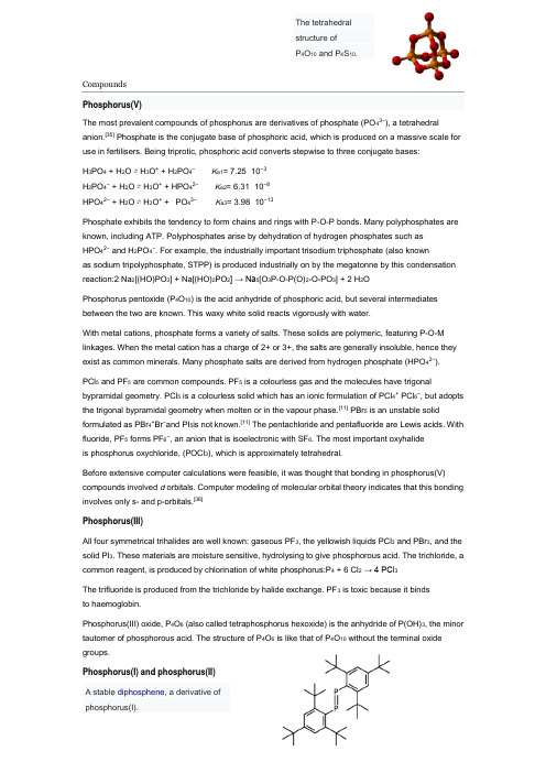
CompoundsPhosphorus(V)The most prevalent compounds of phosphorus are derivatives of phosphate (PO 43−), a tetrahedralanion.[35] Phosphate is the conjugate base of phosphoric acid, which is produced on a massive scale for use in fertilisers. Being triprotic, phosphoric acid converts stepwise to three conjugate bases:H 3PO 4 + H 2O ⇌ H 3O + + H 2PO 4− K a1= 7.25×10⁻³H 2PO 4− + H 2O ⇌ H 3O + + HPO 42− K a2= 6.31×10⁻⁸HPO 42− + H 2O ⇌ H 3O + + PO 43− K a3= 3.98×10⁻¹³Phosphate exhibits the tendency to form chains and rings with P-O-P bonds. Many polyphosphates are known, including ATP. Polyphosphates arise by dehydration of hydrogen phosphates such as HPO 42− and H 2PO 4−. For example, the industrially important trisodium triphosphate (also knownas sodium tripolyphosphate, STPP) is produced industrially on by the megatonne by this condensation reaction:2 Na 2[(HO)PO 3] + Na[(HO)2PO 2] → Na 5[O 3P-O-P(O)2-O-PO 3] + 2 H 2OPhosphorus pentoxide (P 4O 10) is the acid anhydride of phosphoric acid, but several intermediates between the two are known. This waxy white solid reacts vigorously with water.With metal cations, phosphate forms a variety of salts. These solids are polymeric, featuring P-O-M linkages. When the metal cation has a charge of 2+ or 3+, the salts are generally insoluble, hence they exist as common minerals. Many phosphate salts are derived from hydrogen phosphate (HPO 42−). PCl 5 and PF 5 are common compounds. PF 5 is a colourless gas and the molecules have trigonal bypramidal geometry. PCl 5 is a colourless solid which has an ionic formulation of PCl 4+ PCl 6−, but adopts the trigonal bypramidal geometry when molten or in the vapour phase.[11] PBr 5 is an unstable solid formulated as PBr 4+Br −and PI 5is not known.[11] The pentachloride and pentafluoride are Lewis acids. With fluoride, PF 5 forms PF 6−, an anion that is isoelectronic with SF 6. The most important oxyhalideis phosphorus oxychloride, (POCl 3), which is approximately tetrahedral.Before extensive computer calculations were feasible, it was thought that bonding in phosphorus(V)compounds involved d orbitals. Computer modeling of molecular orbital theory indicates that this bonding involves only s- and p-orbitals.[36]Phosphorus(III)All four symmetrical trihalides are well known: gaseous PF 3, the yellowish liquids PCl 3 and PBr 3, and the solid PI 3. These materials are moisture sensitive, hydrolysing to give phosphorous acid. The trichloride, a common reagent, is produced by chlorination of white phosphorus:P 4 + 6 Cl 2 → 4 PCl 3The trifluoride is produced from the trichloride by halide exchange. PF 3 is toxic because it binds to haemoglobin.Phosphorus(III) oxide, P 4O 6 (also called tetraphosphorus hexoxide) is the anhydride of P(OH)3, the minor tautomer of phosphorous acid. The structure of P 4O 6 is like that of P 4O 10 without the terminal oxide groups.Phosphorus(I) and phosphorus(II)The tetrahedralstructure ofP 4O 10 and P 4S 10.A stable diphosphene , a derivative ofphosphorus(I).These compounds generally feature P-P bonds.[11] Examples include catenated derivatives of phosphine and organophosphines. Compounds containing P=P double bonds have also been observed, although they are rare.Phosphides and phosphinesPhosphides arise by reaction of metals with red phosphorus. The alkali metals (group 1) and alkaline earth metals can form ionic compounds containing the phosphide ion, P3−. These compounds react with water to form phosphine. Other phosphides, for example Na3P7, are known for these reactive metals. With the transition metals as well as the monophosphides there are metal rich phosphides, which are generally hard refractory compounds with a metallic lustre, and phosphorus rich phosphides which are less stable and include semiconductors.[37] Schreibersite is a naturally occurring metal rich phosphide found in meteorites. The structures of the metal rich and phosphorus rich phosphides can be structurally complex.Phosphine (PH3) and its organic derivatives (PR3) are structural analogues with ammonia (NH3) but the bond angles at phosphorus are closer to 90° for phosphine and its organic derivatives. It is an ill-smelling, toxic compound. Phosphorus has an oxidation number of -3 in phosphine. Phosphine is produced by hydrolysis of calcium phosphide, Ca3P2. Unlike ammonia, phosphine is oxidised by air. Phosphine is also far less basic than ammonia. Other phophines are known which contain chains of up to nine phosphorus atoms and have the formula P n H n+2. The highly flammable gas diphosphine (P2H4) is an analogueof hydrazine.OxoacidsPhosphorous oxoacids are extensive, often commercially important, and sometimes structurally complicated. They all have acidic protons bound to oxygen atoms, some have nonacidic protons that are bonded directly to phosphorus and some contain phosphorus - phosphorus bonds.[11] Although many oxoacids of phosphorus are formed, only nine are important, and three of them, hypophosphorous acid, phosphorous acid, and phosphoric acid, are particularly important(See the table).NitridesThe PN molecule is considered unstable, but is a product of crystalline phosphorus nitride decomposition at 1100 K. Similarly, H2PN is considered unstable, and phosphorus nitride halogens like F2PN, Cl2PN, Br2PN, and I2PN oligomerise into cyclic Polyphosphazenes. For example, compounds of the formula (PNCl2)n exist mainly as rings such as the trimer hexachlorophosphazene. The phosphazenes arise by treatment of phosphorus pentachloride with ammonium chloride:PCl5 + NH4Cl → 1/n (NPCl2)n + 4 HCl When the chloride groups are replaced by alkoxide (RO−), a family of polymers is produced with potentially useful properties.[38]SulfidesPhosphorus forms a wide range of sulfides, where the phosphorus can be in P(V), P(III) or other oxidation states. The most famous is the three-fold symmetric P4S3 which is used in strike-anywhere matches. P4S10 and P4O10 have analogous structures.[39] Mixed oxyhalides and oxyhydrides of phosphorus(III) are almost unknown.Organophosphorus compoundsCompounds with P-C and P-O-C bonds are often classified as organophosphorus compounds. They are widely used commercially. The PCl3 serves as a source of P3+ in routes to organophosphorus(III) compounds. For example, it is the precursor to triphenylphosphine:PCl3 + 6 Na + 3 C6H5Cl → P(C6H5)3 + 6 NaClTreatment of phosphorus trihalides with alcohols and phenols gives phosphites, e.g. triphenylphosphite: PCl3 + 3 C6H5OH → P(OC6H5)3 + 3 HClSimilar reactions occur for phosphorus oxychloride, affording triphenylphosphate:OPCl3 + 3 C6H5OH → OP(OC6H5)3 + 3 HCl24 27 28 29 30 31 32CompoundsFluorine has a rich chemistry, encompassing organic and inorganic domains. It combines with metals, nonmetals, metalloids, and most noble gases,and usually assumes an oxidation state of −1.[note10] Fluorine's high electron affinity results in a preference for ionic bonding; when it forms covalent bonds, these are polar, and almost always single.MetalsHydrogenHydrogen and fluorine combine to yield hydrogen fluoride, in which discrete molecules form clusters by hydrogen bonding, resembling water more than hydrogen chloride.[123][124][125] It boils at a much higher temperature than heavier hydrogen halides and unlike them is fully miscible with water.Hydrogen fluoride readily hydrates on contact with water to form aqueous hydrogen fluoride, also known as hydrofluoric acid. Unlike the other hydrohalic acids, which are strong, hydrofluoric acid is a weak acid at low concentrations.However, it can attack glass, something the other acids cannot do.Other reactive nonmetalsBoron trifluoride is planar and possesses an incomplete octet. It functions as a Lewis acid and combineswith Lewis bases like ammonia to form adducts.[132] Carbon tetrafluoride is tetrahedral and inert; itsgroup analogues, silicon and germanium tetrafluoride, are also tetrahedral[133] but behave as Lewis acids. The pnictogens form trifluorides that increase in reactivity and basicity with higher molecular weight, although nitrogen trifluoride resists hydrolysis and is not basic.[136] The pentafluorides of phosphorus, arsenic, and antimony are more reactive than their respective trifluorides, with antimony pentafluoride the strongest neutral Lewis acid known.Chalcogens have diverse fluorides: unstable difluorides have been reported for oxygen (the only known compound with oxygen in an oxidation state of +2), sulfur, and selenium; tetrafluorides and hexafluorides exist for sulfur, selenium, and tellurium. The latter are stabilized by more fluorine atoms and lighter central atoms, so sulfur hexafluoride is especially inert.Chlorine, bromine, and iodine can each form mono-, tri-, and pentafluorides, but only iodine heptafluoride has been characterized amongpossible interhalogen heptafluorides.Many of them are powerful sources of fluorine atoms, and industrial applications using chlorine trifluoride require precautions similar to those using fluorine.Noble gasesThese xenon tetrafluoride crystals were photographed in 1962. The compound's synthesis, as with xenon hexafluoroplatinate, surprised many chemists.Noble gases, having complete electron shells, defied reaction with other elements until 1962 when Neil Bartlett reported synthesis of xenon hexafluoroplatinate;xenon difluoride, tetrafluoride, hexafluoride, and multiple oxyfluorides have been isolated since then. Among other noble gases, krypton formsa difluoride, and radon and fluorine generate a solid suspected to be radon difluoride. Binary fluorides of lighter noble gases are exceptionally unstable: argon and hydrogen fluoride combine under extreme conditions to give argon fluorohydride. Helium and neon have no long-lived fluorides,] and no neon fluoride has ever been observed;helium fluorohydride has been detected for milliseconds at high pressures and low temperatures.Organic compoundsImmiscible layers of colored water (top) and much denser perfluoroheptane (bottom) in a beaker; a goldfish and crab cannot penetrate the boundary; quarters rest at the bottom.Chemical structure of Nafion, a fluoropolymer used in fuel cells and many other applicationsThe carbon–fluorine bond is organic chemistry's strongest, and gives stability to organofluorines. It is almost non-existent in nature, but is used in artificial compounds. Research in this area is usually driven bycommercial applications;the compounds involved are diverse and reflect the complexity inherent in organic chemistry.Discrete moleculesThe substitution of hydrogen atoms in an alkane by progressively more fluorine atoms gradually altersseveral properties: melting and boiling points are lowered, density increases, solubility in hydrocarbonsdecreases and overall stability increases. Perfluorocarbons,[note 16] in which all hydrogen atoms are substituted, are insoluble in most organic solvents, reacting at ambient conditions only with sodium in liquid ammonia.The term perfluorinated compound is used for what would otherwise be a perfluorocarbon if not for the presence of a functional group,[157][note 17] often a carboxylic acid. These compounds share many properties with perfluorocarbons such as stability and hydrophobicity,[159] while the functional group augments their reactivity, enabling them to adhere to surfaces or act as surfactants;[160] Fluorosurfactants, in particular, can lower the surface tension of water more than their hydrocarbon-based analogues. Fluorotelomers, which have some unfluorinated carbon atoms near the functional group, are also regarded as perfluorinated.[159]PolymersPolymers exhibit the same stability increases afforded by fluorine substitution (for hydrogen) in discrete molecules; their melting points generally increase too. Polytetrafluoroethylene (PTFE), the simplestfluoropolymer and perfluoro analogue of polyethylene with structural unit –CF2–, demonstrates this change as expected, but its very high melting point makes it difficult to mold;Various PTFE derivatives are less temperature-tolerant but easier to mold: fluorinated ethylene propylene replaces some fluorine atoms with trifluoromethyl groups, perfluoroalkoxy alkanes do the samewith trifluoromethoxy groups,[162] and Nafion contains perfluoroether side chains capped with sulfonicacid groups. Other fluoropolymers retain some hydrogen atoms; polyvinylidene fluoride has half the fluorine atoms of PTFE and polyvinyl fluoride has a quarter, but both behave much like perfluorinated polymers.1。
MXene:A New Family of Promising Hydrogen Storage Medium Qianku Hu,*,†,‡Dandan Sun,†Qinghua Wu,†Haiyan Wang,†Libo Wang,†Baozhong Liu,†Aiguo Zhou,*,†and Julong He§†School of Material Science and Engineering,Henan Polytechnic University,454000Jiaozuo,P.R.China‡Department of Geosciences,Stony Brook University,11794Stony Brook,New York,United States§State Key Laboratory of Metastable Materials Science and Technology,Yanshan University,066004Qinhuangdao,P.R.China *Web-Enhanced Feature*Supporting Informationthe hydrogen molecules(3.4wt%hydrogen storage capacity)reversibly under ambient conditions.Meanwhile,the hydrogenC)were also evaluated,and the results were similar to those ofmembers was expected to be a good candidate for reversibleNowadays hydrogen storage and transport remain a great challenge for its vehicle applications.1,2Storing hydrogen in solid materials is more practical,safe,and economic than that in gaseous or liquid phases.1−4According to the interaction nature between hydrogen and host materials,solid-state storage materials can be classified into two categories:chemisorption of dissociated hydrogen atoms and physisorption of intact hydrogen molecules.Either approach has its own disadvantages. For chemisorption,strong bonding(40−80kJ/mol)5,6between hydrogen atoms and host materials(mainly metal hydrides or complex chemical hydrides)makes it difficult to release hydrogen at moderate temperatures.For physisorption,an ideal sorbent material should possess two fundamental properties:high specific surface area and suitable binding energy(20−30kJ/mol,corresponding to∼0.2−0.3eV)5,7with hydrogen molecules.The sorption-based storage materials studied now mainly comprise carbon-base materials8−12 (including nanotubes,fullerenes,graphene,and nanoporous carbon),metal−organic frameworks(MOFs),13,14and covalent organic frameworks(COFs).15Almost all these materials meet thefirst requirement.For example,both sides of graphene can be utilized to store hydrogen,10,11and the highest Brunauer−Emmett−Teller surface area of MOF tested to date reach about 7000m2/g.16However,the weak binding strength of hydrogen (4−10kJ/mol,physisorption mostly by van der Waals forces)5 is the largest obstacle for the practical application of these materials.17At present these sorption-based hydrogen storage materials can only operate around liquid nitrogen temperature. Metal decorations were employed to increase the bindingenergy of hydrogen on sorption-based materials.A great deal oftheoretical calculation has been conducted to investigate the effects of metal decorations(including alkali,alkaline earth,and transition metals).18−28The transition metal results are more exciting.Via Kubas-type interaction,29the binding energies of hydrogen with the transition metals lies between strong chemisorption and weak physisorption and comes into a desirable range.However,because of their large cohesive energies,transition-metal adatoms have a tendency of aggregating into clusters,20which would significantly reduce the hydrogen storage capacity.30Some calculations show that boron-doping or vacancy defects on carbon adsorbents may prevent the clustering behavior of metal adatoms.27,31,32 However,it is very difficult to fabricate such metal-well-dispersed carbon adsorbents with boron-doping or vacancy defects.Despite these problems,the Kubas-type hydrogen storage mode is still a promising direction.A material,with lightweight,high specific surface area,no metal-clustering behavior and exhibiting Kubas interactions to store hydrogen,is very hopeful to meet the gravimetric storage capacity targetReceived:September25,2013Revised:November20,2013Published:November21,2013(5.5wt %by 2015)33set by the U.S.DOE.However,the discovery and synthesis of such material is of great challenge.Recently,a new family of graphene-like 2D materials,named as MXene,was prepared by exfoliating the counterpart MAX phases in hydro fluoric acid.34,35MAX phases are a large family (>60members)of layered ternary transition-metal carbides or nitrides with a chemical formula M n +1AX n (n =1,2,or 3),where M is a transition metal,A is an A-group element (mostly IIIA or IVA group),and X is C and/or N.36,37To date,the as-synthesized MXene phases include Ti 2C,Ti 3C 2,Ta 4C 3,(Ti 0.5Nb 0.5)2C,(V 0.5Cr 0.5)3C 2,and Ti 3CN.34,35For a new material,it is very important scienti fically and technically to explore its basic properties and potential applications.Good electrical conductivities of bare MXenes were predicted theoretically and can be tuned by termination/functionalization with di fferent groups.34,35,38−40The electrochemical intercala-tion behaviors of Li ions in MXene structures were also investigated experimentally and theoretically,which prove MXene phases are very promising as anode materials of Li-ion battery.41−44In this paper,we investigated the possibility of employing MXene phases as hydrogen storage media by first-principles calculations.We chose Ti 2C as a representative of MXenes on the basis of the following reasons:(i)Titanium is a commonly used decoration element and has been proved to be e ffective for hydrogen storage in carbon-based materials.(ii)The 2D Ti 2C phase has already been synthesized (though with fluorine (F)and/or hydroxyl (OH)termination).35(iii)Except for Sc 2C,Ti 2C possesses the highest surface area per weight among all possible MXene phases,and thus it is expected to have high gravimetric hydrogen storage capacities.Figure 1gives the crystal structures of bulk Ti 2AlC and 2D Ti 2C.In the layeredTi 2AlC structure,Ti −Al bond is relatively weaker than Ti −C bond.Consequently,the layers of Al atoms can be selectively etched by hydro fluoric acid,which results in the formation of the 2D Ti 2C sheets.35The 2D Ti 2C structure is composed of sharing-edge Ti 6C octahedrons,in which,C atoms occupy the octahedral interstitial sites between near-close-packed Ti atoms.One Ti 2C sheet can be simply considered as one graphene sheet coated with a Ti atoms sheet on each side.These Ti atoms indeed are constituent elements of Ti 2C,and thus the problem of aggregation of Ti atoms can be avoided.With the cleavage of Ti −Al bond,all Ti atoms of Ti 2C lie in an unsaturated coordination state,which is an indispensable condition for metal atoms to exhibit the Kubas interactions.5,45On the basis of aforementioned reasons,we think 2D Ti 2C (even most MXene phases)is very likely to be a reversible and high-gravimetric-capacity hydrogen storage material operated under ambient conditions.The purpose of the calculations in this paper is to con firm this speculation.■THEORETICAL METHODS Our first-principles total energy pseudopotential calculationswere performed using the density functional theory (DFT)asimplemented in CASTEP code.46The exchange and correlation energy is described by the local density approximation (LDA)functional.Vanderbilt ultrasoft pseudopotentials were em-ployed within a plane wave basis set with the cuto ffenergy of 480eV.The numerical integration of the Brillouin zone was performed using 6×6×2(unit cell)and 2×2×1(supercell)Monkhorst −Pack (MP)k -point sampling.Both structural parameters and atomic positions with no constraints were fully relaxed using the BFGS minimization method until the convergence tolerance (energy <5.0×10⁻⁶eV,force <0.01eV/Å,stress <0.02GPa and displacement <5.0×10⁻⁴Å)was reached.The binding energy (E b )of H 2with the Ti2C host material was calculated according to the followingequation:=+−+E E nE E n()/n b host H host H 22where E host is the total energy of the host structure (bare Ti 2Cstructure or already adsorbed with some H 2or H),E H 2is thetotal energy of an free H 2,E host+n H 2is the total energy of thehost structure adsorbed with new hydrogen molecules,and n is the number of new adsorbed hydrogen molecules.The binding energy of H atom to the surface of Ti 2C was also calculated like this.■RESULTS AND DISCUSSIONTi 2C Model.The 2D Ti 2C structure was constructed by removing the Al element from the parent Ti 2AlC structure.Thereafter,a vacuum space with a thickness of 20Åwas inserted between the neighboring slabs to avoid arti ficial interactions between them.The optimized lattice constant a for the Ti 2C model is 3.002Å,which is in good agreement with the other result of 3.007Å.38A Ti 2C 3×3periodic supercell (containing nine carbon and eighteen titanium atoms,shown in Figure 2a)was used as thehost material.To investigate the hydrogen adsorption,it is important to first find the favorable adsorption sites.On Ti2C surfaces,there exist three types of high-symmetry sites:top site over a Ti atom at the top surface;hollow_1site above the center of three Ti atoms at the top surface,under which there exists one Ti atom at the bottom surface;and hollow_2site above the center of three Ti atoms at the top surface,under which there exists one C atom at the bottom surface.Hydrogen at Ti2C 3×3Supercell.We first studied theadsorption of a single hydrogen molecule on the Ti 2C 3×3supercell.A H 2molecule was put parallel or perpendicularlyabove the three adsorption sites respectively,and thus six models were constructed,which are shown in Figure 2a.After geometry optimization,the H 2initially locating parallel above the three sites and perpendicularly above the hollow_2site is thermally unstable and dissociates into two H atoms.Nearly all dissociated H atoms occupy the hollow_1site.The calculations (Supporting Information)for one hydrogen atom locating above the top,hollow_1and hollow_2sites,respectively,show that the hollow_1site is the most stable one.Thus it canbeFigure 1.(a)Crystal structure of bulk Ti 2AlC.The black solid line labels out the unit cell.(b)Side views and (c)top views of 2D Ti 2C structure.Two Ti 2C octahedrons were labeled out by green color.understood that the dissociated H atoms prefer to occupy the hollow_1site.We turn our eyes onto the stable A and B adsorption sites in Figure 2a where the H 2molecules are still intact and perpendicular to the surface.However,if initially the H 2molecule is put not perpendicular to the A or B sites but is tilted by an angle (>10°),the H 2molecules also dissociate just like the case of parallel to the surface.Therefore,on the basis of the above calculated results,we can presume that the first batch of H 2molecules arriving onto the clean surface of 2D Ti 2C on the hydrogenation process dissociate into H atoms and then the dissociated H atoms occupy the hollow_1site.A model,labeled as Ti 2C(3×3)_18H shown in Figure 2b,was constructed to represent this situation.In this model,the H atoms are adsorbed on the hollow_1sites on both sides of 2D Ti 2C.The calculated binding energy is 5.027eV per H atom with an H −Ti distance of 1.977Å.The large binding energy means the interaction of dissociated hydrogen atoms with the Ti 2C surface is of strong chemisorption.Hydrogen at Ti 2C(3×3)_18H Model.Next,we studied the adsorption of H 2molecules on the Ti 2C(3×3)_18H structure.Similarly,six models were constructed with one H 2molecule parallel or perpendicularly above the top,hollow_1and hollow_2sites,respectively,as shown in Figure 3.After geometry optimization,the H 2molecule parallel above the hollow_2site (labeled as F)relaxes to parallel above the top site (labeled as D).The H 2molecules for the other five con figurations (A,B,C,D,and E;see labels in Figure 3)still keep the initial sites and orientation.For the A,B,C,and E con figurations,the calculated binding energies are in the range 30−70meV,and the H −H bond length increases slightly by 0.01−0.04Åfrom the value 0.769Åof an isolated H 2.The weak binding energy and the nearly unchanged H −H bond length illuminate the H 2are physisorbed on the A,B,C,and E sites.An interesting and exciting result is about the con figuration that the H 2is adsorbed parallel on the top site (D in Figure 3).For this con figuration,the binding energy is calculated to be 0.237eV,which falls into the desired range 0.2−0.3eV.From the binding energy and elongated H −H bond length,we speculated this interaction nature should be of Kubas type,which would be con firmed later by the results of density of states (DOS).At room temperatures,the hydrogen molecules by physisorption are very little.Therefore,we can presume that under ambient conditions the second batch of H 2molecules arriving on the surface of 2D Ti 2C are adsorbed only parallel on the top site.A model,labeled as Ti 2C(3×3)_18H_18H 2,was constructed as shown in Figure 4a to represent this situation.Inthis model,onto every top site on both sides was laid one H2molecule whose axis is parallel to the surface.The initial orientation of the axes of all the H 2molecules was set to be the same.After optimization,one-third of the H 2molecules rotated 60°clockwise around the c axis,one-third of the H 2molecules rotated 60°counterclockwise around the c axis,and the remaining one-third kept in the original orientation.Theoptimized structure of Ti 2C(3×3)_18H_18H 2is shown inFigure 4b.The optimized structure is more symmetrical thanthe initial structure.The average binding energy for the H2molecules by Kubas-type interaction is 0.272eV per H 2with an H −H bond length of 0.823Å.Hydrogen at Ti 2C(3×3)_18H_18H 2Model.Now weconsider the hydrogen adsorption by physical forces at liquidnitrogen temperatures.At low temperatures,the hydrogen molecules by Kubas-type interaction and the hydrogen atoms by chemisorption are bound tightly to the Ti 2C surfaces.Therefore,the Ti 2C(3×3)_18H_18H 2model was used as the host material to investigate the physical adsorption of hydrogen molecules.For this model,H 2molecules have occupied the top sites.Only the hollow_1and hollow_2sites could be usedtoFigure 2.(a)Adsorption of a single hydrogen molecule at di fferent sites of Ti 2C 3×3supercell.The blue arrows indicate the moving direction ofthe dissociated H atoms.The black solid line labels out the 3×3supercell.(b)Ti 2C(3×3)_18Hmodel.Figure 3.Adsorption of a single hydrogen molecule at di fferent sites of Ti 2C(3×3)_18H model.The calculated binding energies for H 2atdifferent sites were given.The blue arrow indicates the movingdirection of the unstable H 2molecule.The black solid line labels outthe3×3supercell.The legend of di fferent atoms is the same to that in Figure 2adsorb H 2molecules.Four con figurations,as shown in Figure 5,were constructed in which one H 2molecule is put parallel or perpendicularly above the hollow_1and hollow_2sites respectively.All four adsorption sites are found to be stable.The weak binding energies for the four sites mean the nature of physical interaction.For the hollow_1or hollow_2site,thebinding energies of the parallel and the perpendicularcon figurations are very close.Thus,at liquid nitrogentemperatures,both the parallel and the perpendicularcon figurations are possible.Whereas the perpendicularcon figuration has a little higher binding energy than thecorresponding parallel con figuration,the two perpendicularcon figurations were chosen to represent the physisorption ofH 2molecules above the hollow_1and hollow_2sitesrespectively.A model was constructed to represent this situation,in whichevery hollow_1or hollow_2site on both sides of Ti2C(3×3)_18H_18H 2is occupiedby one H 2molecule with its axisperpendicular to the site.After optimization,the H2moleculesabovethe hollow_1site are stable.However,the H 2moleculesabove the hollow_2site depart from the surfaces along the c -axis direction.These should arise from the short distance and the resulting repulsion between the H 2molecules above thehollow_1site and the neighboring hollow_2site.A Ti2C(3×3)_18H_36H2model with theH 2molecules only occupying thehollow_1site of Ti 2C(3×3)_18H_18H 2was constructed.Partsa andb of Figure 6give the top and side views of thismodel.Figure 4.(a)Initial structure of Ti 2C(3×3)_18H_18H 2model.(b)Optimized structure of Ti 2C(3×3)_18H_18H 2model.The black solid line labels out the 3×3supercell.The legend of di fferent atoms is the same to that in Figure2.Figure 5.Adsorption of a single hydrogen molecule at di fferent sites of Ti 2C(3×3)_18H_18H 2model.The calculated binding energies for H 2at di fferent sites were given.The black solid line labels out the 3×3supercell.Figure 6.(a)Top views and (b)side views of the Ti 2C(3×3)_18H_36H 2model that possesses the maximum hydrogen storage capacity.The black solid line labels out the 3×3supercell.The average binding energy is calculated to be 0.109eV per H 2for these 18hydrogen molecules above the hollow_1site.Maximum Hydrogen Storage Capacity.Now all thepossible sites on the Ti 2C surface have been considered to bind hydrogen.In the Ti 2C(3×3)_18H_36H 2structure,one adsorption site only binds one H 2molecule.We attempted to attach more H 2molecules to di fferent adsorption sites.But unfortunately it failed.The new added H 2molecule directly flies away or pushes the neighboring H 2molecule o ffand then occupies its position.Therefore,the Ti 2C(3×3)_18H_36H 2model possesses the maximum hydrogen storage capacity.In this supercell model,18H atoms (1.7wt %)are bound by strong chemical forces,36H atoms (3.4wt %)are bound in molecule form by weak physical forces,and the remaining 36H atoms (3.4wt %)are bound in molecule form by Kubas-type interaction.Under ambient conditions,desorption of chem-isorbed hydrogen cannot take place,and physisorbed hydro-gens are not easy to bind.Only the hydrogen bound by Kubas-type interaction could be adsorbed and released reversibly under ambient conditions.The reversible capacity of 3.4wt %is still considerable and signi ficant for practical applications.Density of States and Mulliken Populations.The Kubas-type interaction between H 2and transition metals has the following features:19,22,45,47(i)Adsorbed H 2molecules keep intact and the bond length is elongated approximately 10%from the bond length 0.75Åof a free H 2molecule.(ii)The binding energy is between the physisorption and the chemisorption and usually lies in the range 0.2−0.8eV.(iii)The bond axis of the adsorbed H 2molecule is not perpendicular to the transition metal.In this paper,the hydrogen molecules adsorbed upon the top sites possess all these features.Hence,we conclude that the binding nature of these hydrogen molecules with Ti 2C should be of the Kubas-type interaction.This Kubas-type interaction is associated with the electron donation of H 2σorbitals into the empty d orbitals of a transition metal,and simultaneously the electron back-donation from the filled metal d orbitals into the H 2σ*antibonding orbitals.23,45Thus the Kubas-type interaction involves the orbital hybridization between the transition metal d orbitals and the H 2σorbitals (including bonding and antibonding).Figure 7gives the partial density of states (PDOS)for the s orbitals of one H 2molecule above the top site and the 3d orbitals of the underlying Ti atom in the model of Ti 2C(3×3)_18H_36H 2.It can be seen that the Ti 3d orbitals are hybridized with the H 2σorbitals in the range −10to −6eV.And the peaks from −2to 0eV correspond to the hybridization of the Ti 3d with the H 2σ*orbitals.These hybridizations are very similar to the results obtained by otherresearches for the adsorption of H 2on Ti atom.19,47The approximately 10%elongation of H −H bond length arises from the decrease of bonding-orbital electrons and theincrease of antibonding-orbital electrons.If excessive electronsare donated from Ti 3d orbitals to H2σ*antibonding orbitals,the H 2molecule will be unstable and then dissociate.It is the reason that in this study the first H 2arriving at Ti atomdissociates into H atoms.This phenomenon is also observed in other literatures.19,20,48,49The Mulliken charge population calculations show every dissociated H atom gains 0.33e totally from the three nearest Ti atoms.This means that every Ti atom donates 0.33e totally to the three nearest H atoms.Meanwhile,due to the smaller electronegativity of Ti than C,every Ti atom donates about 0.35e to the three nearest C atoms.Thus when the second H 2arrives,the Ti atom has no enough charges to destabilize the dihydrogen state.As a result,the second arriving H 2does not dissociate and locates above the top site in a molecular form.And even,no more charges in the Ti atom can be transferred to bind extra H 2molecules.It is the reason thatone Ti atom can bind 4−6H2molecules in other literatures,19,22,47,48but one Ti atom in the 2D Ti 2C can onlybind one H 2molecule by Kubas-type interaction.Ab Initio Molecular Dynamic Simulations.From thebinding energies results,we speculated that the hydrogen molecules bound by Kubas-type interaction could adsorb and desorb reversibly under ambient conditions.To verify this and ascertain the exact desorption temperature,desorption behaviors of hydrogen on Ti 2C were investigated by ab initio molecular dynamic (MD)simulations using the Nosealgorithm.The simulation temperature was set to be 300and400K.The total simulation time was set to be 1.5ps with a time step of 1.0fs.Figure 8gives the snapshots of the Ti 2C(3×3)_18H_36H 2model after 1.5ps molecular dynamic simulations at 300and 400K.(Movies 1,2,3,and 4in mpg format for top and side views of desorption processes of hydrogen are available as Web Enhanced Objects.)At both 300and 400K,all the H 2molecules by chemisorption still stay at the initial sites and all the H 2molecules by physisorption depart from the surfaces.These phenomena can be easily understood from the binding energy results.For the eighteen H 2molecules by Kubas-type interaction,the results at 300K are di fferent with those at 400K.At 400K,nearly half of the H 2molecules by Kubas-type interaction depart from the surface.It should be reminded that the simulation system does not reach the balancebecause the 1.5ps simulation time is not long enough (however,already quite costly in computation time).Thus the temperature 400K provides enough energy for the release of the H 2molecules bound by the Kubas-type interaction.At 300K,only three H 2molecules fly away.And an important phenomenon was observed on the simulation process of 300K.When a released H 2molecule flies over the region of a vacanttop site,the vacant top site can catch and adsorb this H 2molecule again.Thus at 300K mostly the top sites should be saturated with H 2molecules.From the above discussions,the adsorption and desorption of hydrogen by Kubas-typeinteraction can be accomplished in the narrow temperature range 300−400K.Therefore,the MD results give clear evidence that 2D Ti2C is a reversible hydrogen storage material under ambientconditions.Figure 7.Partial density of states (PDOS)for thes orbitalsof one H 2molecule above the top site and the 3d orbitals of the underlying Ti atom in Ti 2C(3×3)_18H_36H 2model.The black dash line represents the Fermi level.Perspectives of MXene Phases as Hydrogen Storage Materials.An important experimental result should be noted that because MXene phases were made in aqueous hydro fluoric acid,the as-fabricated 2D Ti 2C are chemically terminated with fluorine (F)and/or hydroxyl (OH)groups.34,35The binding interactions are so strong.Thus,although e ffort has been made,42bare MXene phases with no surface termination have not been prepared.From our point of view,two routes are possible to obtain bare MXene structures:(i)removing the F and OH groups from the synthesized MXenes by chemical or physical methods;(ii)finding a new way to exfoliate parent MAX phases.This is a big challenge and task for materials scientists and chemists.When the writing of this paper came to a close,we realized that the F-or OH-terminated MXene phases may be also a good hydrogen storage material due to the electrostatic interactions between the F (or OH)anions and the adsorbed H 2.The corresponding calculations are now in progress.When the A elements are removed from the corresponding MAX family,which includes more than 60members,theoretically there exist more than 20MXene phases.These MXene phases have structures and compositions similar to Ti 2C and thus are also expected to be good hydrogen storage materials.To test it,the hydrogen storage properties of 2D Sc 2C and V 2C were calculated in a simple way.We replaced Ti atoms in Ti 2C(3×3)_18H,Ti 2C(3×3)_18H_18H 2,and Ti 2C-(3×3)_18H _36H 2models by Sc and V atoms,respectively.The optimized geometry structures (Supporting Information)for hydrogen adsorbed on Sc 2C and V 2C surfaces are similar to those on the Ti 2C surface.The hydrogens are also bound by three modes:physisorption,chemisorption,or Kubas-type interaction.The binding energies for the H 2on Sc 2C and V 2C by Kubas-type interaction were calculated to be 0.164and 0.242eV per H 2respectively,which are also suitable.Therefore,the studies in this paper opened the door of a house that contains a series of reversible and high-gravimetric-capacity hydrogen storage materials operated under ambient conditions.And the hydrogen adsorption and desorption behaviors could be adjusted by using di fferent MXene phases as hydrogen storage materials.■CONCLUSIONSIn summary,using first-principles total energy pseudopotential calculations,we systematically investigated the possibility of 2D Ti 2C structure (a representative MXene)as hydrogen storage materials.The calculations show that hydrogen can be adsorbed on di fferent sites on both sides of Ti 2C layered structure.Considering all adsorbed hydrogen molecules and atoms,the maximum hydrogen storage capacity was calculated to be 8.6wt %,which meets the gravimetric storage capacity target (5.5wt %by 2015)set by the U.S.DOE.These hydrogen are bound by three modes:chemisorption of the H atom (1.7wt %),physisorption of the H 2molecule (3.4wt %),and Kubas-type binding of the H 2molecule (3.4wt %)with calculated binding energies of 5.027,0.109,and 0.272eV,respectively.The binding energy of 0.272eV for the H 2molecule by Kubas-type interaction just falls into the desired range for a reversible hydrogen storage material under ambient conditions.Ab-initioMD simulations con firmed that the hydrogen molecules bound by Kubas-type interaction can be adsorbed and released reversibly in the temperature range 300−400K.The di fferent binding energy values for the three modes imply that 2D Ti 2C can store hydrogenat low,room,and high temperatures.The hydrogen storage properties of Sc 2C and V 2C MXene phases were also evaluated in a simple way.The results are similar to that for Ti 2C and are also fascinating.Therefore,MXene phases including more than 20members should be a new family of hydrogen storage materials.Experiments areexpected to con firm the results of this work.And furtherexperimental and computational investigations should be conducted on other MXene phases.Discovery of MXene phases with better hydrogen storage performances is anticipated in the near future.■ASSOCIATED CONTENT *Supporting Information Adsorption geometries and total energies and structural parameters of all the optimized con figurations involved in this paper.This material is available free of charge via the Internet at .*Web-Enhanced Features Four animations in mpg format are available in the HTML version of the paper.■AUTHOR INFORMATION Corresponding Authors*Q.Hu:e-mail,hqk@.*A.Zhou:e-mail,zhouag@.NotesThe authors declare no competing financial interest.■ACKNOWLEDGMENTS This work was supported by National Natural Science Foundation of China (Grant Nos.51202058,50802024,Figure 8.Top and side snapshots of Ti 2C(3×3)_18H_36H2modelafter 1.5ps moleculardynamic simulations at 300and400K.Severalhydrogen molecules departing too far from the surfaces were not given.The legend of di fferent atoms is the same to that in Figure 2.。
1 Introduction教学目的: List six different property classifications of materials that determine their applicability. Cite the four components that are involved in the design, production and utilization of materials, and briefly describe the interrelationship between these components.教学重点: The four components that are involved in the design, production and utilization of materials教学难点: The discipline of materials science involves investigating the relationships that exist between the structure and properties of materials.教学方法:Multimedia学时分配1.1Historical Perspective10 min1.2Materials science and engineering 25 min1.3Why Study Materials Science and Engineering 10 min1.4Classification of Materials 35 min1.5 Modern Material‟s Needs 10 min教学过程及主要内容:1. Historical PerspectiveWebster编者“New International Dictionary(1971年)”中关于材料(Materials)的定义为:材料是指用来制造某些有形物体(如:机械、工具、建材、织物等的整体或部分)的基本物质(如金属、木料、塑料、纤维等)迈尔《新百科全书》中材料的含义:材料是从原材料中取得的,为生产半成品、工件、部件和成品的初始物料,如金属、石块、木料、皮革、塑料、纸、天然纤维和化学纤维等等。
3,3'-二甲基-4,4-二氨基二环己基甲烷固化工艺一、基本信息CAS:6864-37-5中文名称:3,3'-二甲基-4,4-二氨基二环己基甲烷英文名称:Dimethyldicyane常用名:3,3’-二乙基-4,4’-二氨基二环己基甲烷英文别名:3,3’-Dimethyl-4,4’-diaminodicyclohexylmethane分子式:C15H30N2分子量:238.41二、物理化学性质[ 密度 ]:0.9±0.1 g/cm³[ 沸点 ]:289.6±8.0 ℃ at 760 mmHg[ 熔点 ]:-7℃[ 分子式 ]:C15H30N₂[ 分子量 ]:238.412[ 闪点 ]:152.3±17.9 ℃[ 精确质量 ]:238.240906[ PSA ]:52.04000[ LogP ]:3.47[ 外观性状 ]:无色至黄色液体[ 蒸汽压 ]:0.0±0.6 mmHg at 25℃[ 折射率 ]:1.482[ 计算化学 ]:1.疏水参数计算参考值(XlogP):2.82.氢键供体数量:23.氢键受体数量:24.可旋转化学键数量:25.互变异构体数量:无6.拓扑分子极性表面积527.重原子数量:178.表面电荷:09.复杂度:21710.同位素原子数量:011.确定原子立构中心数量:012.不确定原子立构中心数量:613.确定化学键立构中心数量:014.不确定化学键立构中心数量:015.共价键单元数量:1三、MSDS模块1. 化学品1.1 产品标识符产品名称 : 4,4′-亚甲基双(2-甲基环己胺),异构体混合物1.2 鉴别的其他方法无数据资料1.3 有关的确定了的物质或混合物的用途和建议不适合的用途仅用于研发。
不作为药品、家庭或其它用途。
模块2. 危险性概述2.1 GHS-分类急性毒性, 经口 (类别 4)急性毒性, 吸入 (类别 3)急性毒性, 经皮 (类别 3)皮肤腐蚀 (类别 1A)严重眼睛损伤 (类别 1)急性水生毒性 (类别 2)慢性水生毒性 (类别 2)2.2 GHS 标记要素,包括预防性的陈述象形图警示词危险危险申明H302吞咽有害。
工 程 塑 料 应 用ENGINEERING PLASTICS APPLICATION第49卷,第6期2021年6月V ol.49,No.6Jun. 2021153doi:10.3969/j.issn.1001-3539.2021.06.027羧基丁腈橡胶改性环氧树脂制备及性能臧家庆1,李海柱1,仪海霞1,徐勤福1,邓桃益1,冯永强1,谢庆祥2(1.济南北方泰和新材料有限公司,济南 250033; 2.中国兵器工业集团第五三研究所,济南 250031)摘要:用羧基液体丁腈橡胶(CTBN)对环氧树脂(EP)进行改性,先生成EP /CTBN 预聚物,再以651聚酰胺树脂及一定量的聚醚胺作为内增韧型固化剂固化成型。
采用红外光谱对预聚物进行结构表征,测试了不同CTBN 含量改性EP 固化后的冲击强度、拉伸剪切强度、玻璃化转变温度、外观、断裂形貌。
结果表明,EP 中的环氧基与CTBN 中的羧基发生反应,CTBN 接枝到EP 上。
随着CTBN 含量增加,改性EP 的冲击强度和拉伸剪切强度都有明显提高,断裂形貌呈现出韧性断裂特征,增韧效果显著。
当CTBN 质量分数为15%时,拉伸剪切强度最大,比未改性时提高了34.6%。
当CTBN 质量分数为25%时,增韧EP 的同时耐热性并没有降低。
关键词:羧基液体丁腈橡胶;环氧树脂;预聚物;增韧改性中图分类号:TQ32 文献标识码:A 文章编号:1001-3539(2021)06-0153-04Preparation and Properties of CTBN Modified Epoxy ResinZang Jiaqing 1, Li Haizhu 1, Yi Haixia 1, Xu Qinfu 1, Deng Taoyi 1, Feng Yongqiang 1, Xie Qingxiang 2(1. Jinan North Taihe New Material Co., Ltd., Jinan 250033,China ; 2. Institute 53, China North Industries Group , Jinan 250031,China)Abstract :Liquid carboxyl terminated butadiene nitrile rubber (CTBN) was used to modify epoxy resin (EP). CTBN /EP prepolymer was prepared and then cured with 651 polyamide resin and a certain amount of polyether amine as internal toughening curing agent. The structure of the prepolymer was characterized by infrared spectroscopy. The impact strength ,tensile shear strength ,glass transition temperature and appearance fracture morphology of the cured EP modified with different content of CTBN were tested. The results show that the epoxy group in EP reacts with the carboxyl group in CTBN ,and CTBN is grafted onto EP. With the increase of CTBN content ,the impact strength and tensile shear strength of the modified EP are significantly improved ,and the fracture morphology shows the characteristics of ductile fracture ,and the toughening effect is significant. When CTBN mass fraction is 15%, the tensile shear strength reaches the maximum ,which is 34.6% higher than that of unmodified CTBN. When the mass fraction is 25%,the toughening of EP does not decrease the heat resistance.Keywords :liquid carboxyl terminated butadiene nitrile rubber ;epoxy resin ;prepolymer ;toughening modification环氧树脂(EP)作为一类重要的热固性树脂,具有固化方便、力学性能高、固化收缩率小、粘接性能优异、力学性能及电性能优异、加工成型简便、成本低廉、化学稳定性能好等优点,所以在电子电器、汽车、机械、航天航空等领域得到广泛的应用。
Chemical Bonding in Group III NitridesAurora Costales,†,‡Miguel A.Blanco,*,†AÄngel Martı´n Penda´s,†Anil K.Kandalam,§and Ravindra Pandey§Contribution from the Departamento de Quı´mica Fı´sica y Analı´tica,Facultad de Quı´mica, Uni V ersidad de O V iedo,33006-O V iedo,Spain,and Department of Physics,Michigan Technological Uni V ersity,Houghton,Michigan49931Received October24,2001Abstract:We analyze in this article the evolution of the chemical bonding in group III nitrides(MN,M)Al, Ga,In),from the N-N bond dominated small clusters to the M-N bond dominated crystals,with the aim of explaining how the strong multiple bond of N2is destabilized with the increase in coordination.The picture that emerges is that of a partially ionic bond in the solid state,which is also present in all the clusters.The covalent N-N bond,however,shows a gradual decrease of its strength due to the charge transfer from the metal atoms.Overall,Al clusters are more ionic than Ga and In clusters,and thus the N-N bond is weakest in them.The nitrogen atom charge is seen to be proportional to the metal coordination, being thus a bond-related property,and dependent on the M-N distance.This explains the behavior observed in previous investigations,and can be used as a guide in predicting the structures and defects on semiconductor quantum dot or thin film devices of these compounds.1.IntroductionGroup III(Al,Ga,and In)nitrides are gathering much attention from both the theoretical and experimental fields.The main reason behind this is their growing importance in the preparation of electronic devices.1Thus,the structural and electronic properties of the pure crystals of these compounds have been widely studied(see ref2and references therein). However,it is thin films,and not bulk crystals,that are used in electronic devices,and in these arrangements there is substantial disorder,with low coordination structures due to unsaturated bonds on the surface.To better understand these type of structures,finite clusters may be of help.3In contrast to the wealth of results for the solid-state nitrides, studies on group III nitride clusters are scarce.4-8Our group has conducted a series of DFT structural studies on these clusters,9-12including some preliminary bonding results.10The picture emerging from these studies is clearly dominated by the existence of strong N-N bonds of multiple character,in the form of either N2units or N3azide-like units.This is very different from the bonding in the solid state,with4-fold coordinated metals and nitrogens,and no N-N or metal-metal bonds.In the case of the clusters,Al-N bonded structures start to dominate at the trimer size,with a2-fold coordination on both types of atoms.In the case of Ga and In nitride,however, preliminary results for(MN)n clusters with n)4,5,and612 indicate that N atoms without N-N bonding require at least three of the weaker Ga-N or In-N bonds.This requires a corresponding concentration of N atoms(either as N2or as N3 units)in another part of the cluster when we consider stoichio-metric clusters,suggesting that N segregation may occur during quantum dot or thin film deposition processes.In this article,our aim is to explain how(or whether)the N-N bond weakens upon increasing the coordination of metals around the nitrogen.To accomplish this,we will study different series of clusters and compare them with the crystalline form to seek the emergence of bulklike bonding properties as the metal-nitrogen coordination increases.Particularly,we will address the bonding in three different ways:first,we will look at the bonding in terms of bond lengths and geometries;then, we will try to extract some bonding information from the relative energetic stabilities,that is,the binding;finally,we will use the Atoms in Molecules(AIM)theory to obtain atomic charges*Corresponding author.E-mail:mblanco@.Temporary ad-dress:Department of Physics,Michigan Technological University.Hough-ton,MI49931.‡Temporary address:Department of Physics,Michigan Technological University,Houghton,Michigan49931.†Universidad de Oviedo.§Michigan Technological University.(1)Nakamura,S.In Proceedings of International Symposium on Blue Laserand Light Emitting Diodes;Yoshikawa,A.,Kishino,K.,Kobayashi,M., Yasuda,T.,Eds.;Chiba University Press:Chiba,1996;p119.(2)Serrano,J.;Rubio,A.;Herna´ndez,E.;Mun˜oz,A.;Mu´jica,A.Phys.Re V.B2000,62,16612-23.(3)Belyanin,A.F.;Bouilov,L.L.;Zhirnov,V.V.;Kamenev,A.I.;Kovalskij,K.A.;Spitsyn,B.V.Diam.Relat.Mater.1999,8,369.(4)Langhoff,S.R.;Bauschlicher,C.W.,Jr.;Pettersson,L.G.M.J.Chem.Phys.1988,89,7354.(5)Nayak,S.K.;Khanna,S.N.;Jena,P.Phys.Re V.B1998,57,3787.(6)BelBruno,J.J.Chem.Phys.Lett.1999,313,795.(7)Timoshkin,A.Y.;Bettinger,H.F.;Schaefer,H.F.J.Am.Chem.Soc1997,119,5668.(8)Andrews,L.;Zhou,M.;Chertihin,G.V.;Bare,W.D.;Hannachi,Y.J.Phys.Chem.A2000,104,1656.(9)Kandalam,A.;Pandey,R.;Blanco,M.A.;Costales,A.;Recio,J.M.;Newsam,J.M.J.Phys.Chem.B2000,104,4361.(10)Costales,A.;Kandalam,A.K.;Martı´n Penda´s,A.;Blanco,M.A.;Recio,J.M.;Pandey,R.J.Phys.Chem.B2000,104,4368.(11)Kandalam,A.K.;Blanco,M.A.;Pandey,R.J.Phys.Chem.B2001,105,6080-4.(12)Kandalam,A.K.;Blanco,M.A.;Pandey,R.J.Phys.Chem.B2002.Published on Web03/22/200241169J.AM.CHEM.SOC.2002,124,4116-412310.1021/ja017380o CCC:$22.00©2002American Chemical Societyand bonding properties from the quantum mechanical calcula-tions,by analyzing the topology of the electron density.putational DetailsThis article contains results from three types of systems,each one treated in a different but comparable way.First,in group III nitride clusters,the main subject of this report,we have used a procedure similar to the one outlined in ref10,and we have also included results already presented in refs9and10(MN,M2N2,and M2N2-2clusters) to aid in determining the trends.Second,we have done calculations on N2and the N2H2and N2H4hydrides,to serve as a pattern of well-behaved triple,double,and single N-N covalent bonds.And third, we have also studied the crystals of the group III nitrides,as the infinite-limit of the cluster-growing process.We will describe each of these types of calculations in turn.For the nitride clusters,the procedure begins with a DMol13 optimization of the desired structure.This is a Density Functional Theory(DFT)computational scheme,in which double- numerical basis sets supplemented with polarization functions(DNP basis set)are used in a Linear Combination of Atomic Orbitals-Self-Consistent Field (LCAO-SCF)Kohn-Sham calculation.We have employed the Gen-eralized Gradient Approximation(GGA)functionals of Becke14and of Perdew and Wang15to describe the exchange and correlation effects, respectively(BPW91).Numerical details of the SCF and symmetry-constrained optimization have been given elsewhere.9To obtain analytical densities to perform Atoms in Molecules(AIM) calculations,16we have performed single-point DFT-BPW91calcula-tions using6-31G*basis sets within the Gaussian9817program(see ref10for a justification of the equivalence of the DMol and Gaussian basis sets).To make the comparison with the hydrides and crystals consistent,we have taken the Gaussian single-point and atomic energiesto compute binding energies.As the final step in cluster calculations, we have used the AIMPAC9518package to integrate AIM properties using the PROMEGA algorithm.In the second type of systems,N2and N2H m hydrides,we have optimized the geometries directly with Gaussian,obtaining the bond properties with AIMPAC95.The structures used were the planar C2h structure for N2H2and the trans,also C2h,structure for N2H4.Both of them are the most stable structures at the level of theory employed, BPW91/6-31G*.Although the experimental structure of the three group III nitrides considered is the hexagonal B4structure,we have used the cubic B3 structure(F4h3m,with atoms in Wyckoff positions4a and4c),which is attainable as a metastable phase by epitaxial deposition.The B3 structure is more symmetric,with a single kind of M-N bonds,being thus better suited as a crystalline reference example.Both structures consist of vertex-sharing NM4tetrahedra,with different interplanar packings which affect only the third-nearest and further neighbor distances when comparing the ideal B4structure,bearing the same relationship as the hcp and fcc structures in elemental solids.In the case of the MN B4phases,the tetrahedra are almost regular,with nearest-neighbor distances of1.86/1.90(AlN),1.94/1.946(GaN),and 2.13/2.16Å(InN).19We have selected a B3configuration equivalent to the experimental one by putting the volume per formula unit of the B3phase equal to that of the B4,which gives nearest-neighbor distances of1.888,1.944,and2.154Åfor Al,Ga,and In nitrides in the B3 phase,very close to the average B4distance.We have performed CRYSTAL9520BPW91LCAO calculations for the three crystals at this experimental-like configuration,using the same basis set as in the molecular calculations to facilitate the comparison.21III.ResultsIn this section,we will present the results of our calculations in three series of clusters,each one designed to test how the N-N bond behaves when its coordination increases in a different way.The first series,M m N2-2series(m)2,4,6), adds terminal metal atoms to N2,increasing the coordination while maintaining a N-N bond.Since the solid-state environ-ment is tetrahedral,we have devised two further series of clusters:the edge-sharing tetrahedra M m N2series(m)2,4, 6),with two bridge atoms,and the face-sharing tetrahedra M m N2 series(m)3,5),with three bridge atoms.Vertex-sharing tetrahedra configurations,although the most similar to the solid state,were ignored due to the extremely low symmetries they lead to.The structures used for these clusters are shown in Figure1.Despite the fact that the clusters are arranged in three series, we will present the results in a property-wise manner,leaving the discussion of the general trends in each series to the conclusions section.In the next subsections,we will first assess geometrical properties,followed by the study of the relative stabilities,then we will present the atomic charges,and we will conclude with the AIM bond properties.A.Geometry.Table1presents the nearest-neighbor distances and binding energies per atom for all the clusters studied here.(13)Dmol user guide,version2.3.6.Molecular Simulations,Inc.,1995.(14)Becke,A.D.Phys.Re V.A1988,38,3098.(15)Perdew,J.P.;Wang,Y.Phys.Re V.B1992,45,13244.(16)Bader,R.F.W.Atoms in Molecules;Oxford University Press:Oxford,1990.(17)Gaussian98;Gaussian,Inc.:Pittsburgh,PA,1998.(18)Keith,T.A.;Laidig,K.E.;Krug,P.;Cheeseman,J.R.;Bone,R.G.A.;Biegler-Ko¨nig,F.W.;Duke,J.A.;Tang,T.;Bader,R.F.W.The aimpac95 programs,1995.(19)Wyckoff,R.W.G.Crystal Structures;Interscience Publishers Inc.:NewYork,1960;Vol.II.(20)Saunders,V.R.;Dovesi,R.;Roetti,C.;Causa`,M.;Harrison,N.M.;Orlando,R.;Zicovich-Wilson,C.M.;Torino,Crystal95user’s manual, 1995.(21)The most diffuse exponents were reoptimized to avoid linear dependence,as is usual with CRYSTAL95calculations.Figure1.Schematic representation of the structures of M m N2(M)Al, Ga,In)rge black circles represent metal atoms,small open circles are N atoms.Thick bonds come up from the plane,thick dashed bonds go below the plane.Thin dotted lines represent bonds that are present only for some compounds(see Subsection3.4).Chemical Bonding in Group III Nitrides A R T I C L E SJ.AM.CHEM.SOC.9VOL.124,NO.15,20024117We will start focusing on the d h(homonuclear N-N)distances, which will be compared with the corresponding distances for N2and N2H m hydrides included in Table2.Looking at these distances,they can clearly be classified into different categories. First of all,N2gets a category by itself,with the shortest N-N distance of all.Then,M2N2-2,N2H2,and M2N2,with distances in the range1.2-1.3Å.M6N2-2have an intermediate distance, 1.30-1.35Å.M3N2,N2H4,and M4N2-2share the range1.45-1.55Å,with the exception of Al3N2,which has a longer distance of1.86Å.All of the M4N2,M5N2,and M6N2display much larger distances(>2.3Å).These categories can then be naı¨vely labeled as having triple, double,single,and no N-N bonding,with the M6N2-2having a very special place.However,it should not be implied that these clusters conform to the s and p covalent bonding scheme of,i.e.,organic compounds or the N2H m hydrides used here as a pattern.To begin with,no Lewis configuration of shared electron pairs can be found to justify single bonds in M3N2, nor double bonds in M2N2,and M6N2-2nitrogens will have a quite strange pairing scheme.To understand the bonding on these clusters,we cannot interpret M-N bonds as electron-pair covalent bonds,as we shall see later.N-N bonds can neverthe-less be attributed an essentially covalent nature,owing to their nonmetal homonuclear character,whenever they exist.As to the existence of these bonds in edge-and face-sharing clusters, we will delay the discussion to Subsection III.D.Before comparing the M-N distances of the different clusters studied,we should present the two end-limits of M-N bonding. On one hand,as presented in refs9and10,MN diatomic molecules have distances of1.82,2.06,and2.28Åfor M) Al,Ga,and In,respectively,with AIM charges of0.9e for Al and around0.5for Ga and In,resulting in a partially ionic bonding.On the other extreme,the MN B3experimental-like (see Section II)crystals show a tetrahedral environment for both M and N.The geometric,energetic,and bonding properties of these crystals are presented in Table3.As can be seen,the AIM charges are larger,giving rise to a more ionic bonding,whereas the distances are smaller than those in the diatomics except for AlN.This can be understood comparing the atomic radius in the bond direction(rN and rM in Table3,d N and d-d N in Table3of ref10):both the N and the M radii decrease in forming the GaN and InN solids,whereas the Al radius remains constant and the N radius increases in forming the AlN solid. This may be due to the high negative charge of the N atom in the solid,tending to increase its radius.To discuss the M-N distances in Table1,it is best to sort them into two categories:terminal M-N bonds,listed in column d t,and d2for the second M6N2-2distance,and bridge M-N bonds,listed in column d b and the remaining entries of column d2.Let us start with terminal M-N bonds.These bond lengths cluster around the MN B3solid and diatomic distances, with Al m N n distances being the shortest,followed by Ga m N n, and with In m N n having the longest terminal M-N bonds.The only exceptions to this ordering are Ga5N2,with a somewhat shorter Ga-N bond than the other compounds,and the second kind of Al-N distances in Al6N2-2,much larger than the other. M5N2terminal bonds are in fact among the shortest for each metallic element,together with the M4N2,while both M6N2-2 M-N bonds are the longest.However,whereas both types of M-N bonds have almost the same length in Ga6N2-2and In6N2-2,they are very different in Al6N2-2.The unexpected behavior of M6N2-2clusters,with N-N distances between those of M2N2-2and M4N2-2clusters and longer M-N distances,deserves some further attention.As previously stated,N atoms usually form only three covalent bonds,except when they act as a Lewis base and share its remaining lone electron pair.This is not the case for these clusters,since the N atoms carry a significant negative charge as we shall see in the next subsection.In addition,the N-N bond has a distance shorter than those corresponding to single bonds,indicating a considerable double bond character.Par-ticularly for Ga6N2-2and In6N2-2,these clusters can beTable1.Interatomic Distances(Å)of the Various Nitride Clusters under Study acluster d h d t d b d2E bindAl2N2-2 1.226 1.921-2.885 Al4N2-2 1.571 1.871-2.853 Al6N2-2 1.299 1.875 2.364-2.361 Al2N2 1.296 2.100-3.083 Al4N2 2.764 1.865 1.872-3.222 Al6N2 2.989 1.914 2.173-2.852 Al3N2 1.859 1.894 2.022-2.842 Al5N2 2.550 1.867 1.904 2.118-3.011 Ga2N2-2 1.212 2.027-2.840 Ga4N2-2 1.509 1.963-2.786 Ga6N2-2 1.341 2.039 2.041-2.635 Ga2N2 1.274 2.201-2.989 Ga4N2 2.828 1.935 1.931-2.952 Ga6N2 3.194 1.957 2.292-2.803 Ga3N2 1.448 2.273 2.162-2.634 Ga5N2 2.342 1.884 2.122 2.122-2.821 In2N2-2 1.197 2.286-2.628 In4N2-2 1.438 2.165-2.214 In6N2-2 1.347 2.295 2.308-2.070 In2N2 1.253 2.436-2.750 In4N2 3.101 2.134 2.144-2.300 In6N2 3.188 2.166 2.413-2.253 In3N2 1.412 2.476 2.374-2.296 In5N2 2.475 2.117 2.356 2.356-2.260a Symbols are defined in Figure1:d h is the homonuclear nitrogen-nitrogen distance,d t corresponds to terminal M-N bonds,db to bridge M-N bonds,and d2(when present)to the second kind of terminal or bridge M-N bonds.The last column gives the binding energy per atom(in eV).Table2.Evolution of the N-N Bond in the Hydride Series a molecule d h E bind/N F h∇F hN2 1.116-5.0190.644-2.076N2H2 1.257-3.2880.461-1.056N2H4 1.503-3.1590.263-0.386a Homonuclear N-N distance(d h,inÅ),binding energy per atom(E bind/ N,in EV),and electron density(F h,in electrons/Bohr3)and its Laplacian (∇F h,in electrons/Bohr5)at the homonuclear bond point.Table3.B3Phase Crystal Properties acrystal AlN GaN InNa 4.360 4.489 4.974d 1.888 1.944 2.154E bind/N-5.559-3.155-3.762Q N-2.387-1.615-1.492f N0.7880.5710.478F0.0750.1020.084∇2F0.4580.3820.303r N 1.114 1.027 1.060r M0.7740.916 1.094a Lattice parameter(a),nearest-neighbor distance(d),and nitrogen radius along the bond direction(r N)inÅ,nitrogen atomic charge(Q N)in electrons, and bond point electronic density(F)and Laplacian(∇2F)in atomic units.E Bind/N is the binding energy per atom(in eV).f N is the volume fraction occupied by the N atom.A R T I C L E S Costales et al. 4118J.AM.CHEM.SOC.9VOL.124,NO.15,2002considered as a N 2molecule accepting charge transfers from a set of metal atoms,and thus increasing its N -N distance,but forming very weak bonds with them,explaining the longer M -N distances.In fact,the Ga and In atoms show an almost regular octahedral structure,with the N 2molecule inside (see Figure 2).The distances between metal atoms are,however,too large to be considered as bonded: 3.15-3.39and 3.61-3.80Åfor the Ga and In clusters,respectively,whereas the distances for the M 2cluster/M metallic solid are 2.80/2.44and 3.17/3.25Åfor M )Ga and In,respectively.Thus,the metal atoms can be regarded as having a nondirectional bond with N 2,and packing around it in the least interaction geometry,an octahedron.In the case of Al 6N 2-2,however,the N 2molecule is too large to fit inside an octahedron of noninteracting Al,and thus the preferred structure (see Figure 2)resembles that of a Al 2N 2-2cluster,almost linear and with similar distances,with two long-distance M -N bonds on each N atom that leave an almost equilateral (the unique angle is 61.3°)Al triangle at each end of the molecule.The Al 6geometry is that of an octahedron enlarged along one of its S 3axes,with the nitrogen molecule oriented along one of the former C 4axes and further displacing both triangles.The existence of a linear Al -N -N -Al unit indicates that this is not just a steric effect,but that also electronic structure preferences play some role here.With respect to the bridge M -N bond distances,the main trend is again to sort themselves by the metallic atom involved,with the Al -N distances being generally smaller than those of Ga -N,and these in turn smaller than those of In -N.However,there are several exceptions to this trend,the most important being that of the M 4N 2clusters,with a much shorter bridge bond length than all other metallic bridge atoms,on the order of magnitude of terminal bonds.All the other bridge distances tend to be larger than terminal distances,and they have a much wider range of values.Thus,although bridge atoms should be the metallic atoms closer to the solid-state behavior,the tendency to form N -N bonds puts a lot of stress into these bonds.The N -M -N bond angles are around 30°for M 2N 2and M 3N 2(except Al 3N 2,around 55°),corresponding to a short N -N distance.They are around 65°for M 5N 2(again except Al 5N 2,around 84°),corresponding to long-range N -N bonding.Finally,the angles are close to 90°for M 6N 2(<90°)and M 4N 2(>90°),making an almost perfect square.It should be kept in mind that,were the environment around the N atoms a perfect tetrahedron,the M -N -M angle would be around 70°for edge-sharing and around 39°for face-sharing tetrahedra.The actual values are either much smaller or much larger than these,except for Ga 3N 2and In 3N 2,indicating a clear departure from the tetrahedral environment in all but these two compounds.In fact,even in these two compounds the similarity is fortuitous,since there is a quite clear covalent N -N bond,as we shall show in Subsection III.D.B.Stability.The last column of Table 1contains the binding energy (E bind )per atom of all M m N n clusters.The binding energy,being defined as the total energy of the cluster minus that of the separate atoms,is obviously larger for clusters of bigger sizes.To ease the comparison of the relative stabilities of the differently sized clusters,the binding energy per atom is commonly used.However,this magnitude cannot be used in thermodynamic relations,and should not be considered as an indication of bond strength but of overall stability.As was expected,the largest E bind per atom values correspond to the N 2molecule,N 2H m hydrides (see Table 2),and the B3MN crystals (see Table 3).In the first two cases,the stability is probably coming from the strong covalent bonding,whereas the B3crystals,with a bonding quite similar to that of the M m N n clusters,as we shall see,has nevertheless all tetrahedral valences of N and M atoms saturated,bringing a tighter binding for each.It is important to remember that the diatomic MN molecules (with binding energies per atom of -1.307,-1.196,and -1.001eV for M )Al,Ga,and In)are by far the clusters with lower overall stability,corresponding to minimal coordination.Among the clusters,Al ones are usually more stable,followed by Ga and then In.Al 6N 2-2has an exceptionally low binding energy,and Ga 6N 2-2and In 6N 2-2are also among the less stable clusters,indicating the very weak overall bonding of the six metal atoms to the inner N 2molecule.An interesting concept arises if we focus on the number of bonds in each structure.If,instead of dividing E bind by the number of atoms in the cluster,we calculate the binding energy per bond,counting as such those in the conventional skeleton of the molecule depicted in Figure 1,we will get a better measure of the average strength of the bonds of each cluster.This completely changes the picture.There is still an overall ordering Al/Ga/In,and N 2and N 2H 2,with strong covalent bonds,are the ones with a larger stabilization per bond.However,the B3phase crystals,with four bonds per unit formula,show in fact the weaker bonds in GaN and InN,and only an intermediate strength bond in AlN.This may be explained as a consequence of the larger ionic character of the crystals when compared with the clusters,with the Al -N bond being stronger because of the larger charge transfer (see the next subsection):the Coulomb binding energy is proportional to the square of the ionic charge,and inversely proportional to the nearest-neighbor distance.A clearer order is also established among the clusters:M 2N 2-2and M 4N 2-2,in this order,are the clusters with larger binding energies per bond,corresponding to short N -N distances accompanied by short M -N distances.Then come the M 6N 2-2clusters,with short N -N bonds and intermediate M -N ones,except for Al 6N 2-2,which has a very long M -N distance and a lower binding energy per bond.M 4N 2and M 6N 2come next,with short M -N distances and no N -N interaction.Finally,M 2N 2,MN,M 5N 2,and M 3N 2show the lowest binding energies per bond of the M m N n clusters.M 2N 2clusters have a very strong and short N -N bond,but also four very long,weak M -N bonds,which lower the average binding energy.MN diatomics still show a weak bond when compared with the previous clusters,to which no clear explanation has been found.Finally,M 5N 2and M 3N 2show very strained N -N and M -N interactions due to their crowded coordinations,showing also quite long M -Nbonds.Figure 2.Optimized geometry of Al 6N 2-2and Ga 6N 2-2.Chemical Bonding in Group III Nitrides A R T I C L E SJ.AM.CHEM.SOC.9VOL.124,NO.15,20024119C.Atomic Charges and Ionicity.For the discussion of ionicity we have selected AIM atomic charges.Other schemes (e.g.,Mulliken)produce different values for the charge,although the trends,our main focus in this paper,are very similar. Moreover,Mulliken charges are very sensitive to the details of the calculation,whereas AIM charges,derived from the electronic density,are molecular-orbital independent and con-sistent across series of compounds.The AIM charges for all the clusters studied are gathered in Table4.As a reference, charges for the B3crystal atoms are also included in Table3, and the atomic charges computed for the MN diatomic molecules in ref10were0.919,0.542,and0.528for the Al, Ga,and In atoms,respectively.Looking at the charges of the N atoms in the diatomics,clusters,and solid,it is easy to conclude that they depend mainly on the coordination number. Roughly speaking,the more M atoms surrounding a N atom, the more charge that is transferred to it,in an amount that seems to be very similar for each new M atom in the N coordination sphere.Thus,M6N2clusters show the highest N charges for M )Al,Ga,and In,with values almost equal to those of the B3 phase,as the tetrahedral coordination of N would suggest.These charges are very high,indicating a very ionic bonding,especially in the case of AlN and Al6N2.After these,the N atoms in M5N2 follow,having a similar charge to the3-fold coordinated M4N2, probably because of the strain in the face-sharing environment. This also lowers the charge of the M3N2clusters,with a3-fold coordination but a face-sharing environment.M2N2and M2N2-2 have the smallest charges,in agreement with their M atoms loosely bound to a tightly bonded N2unit.The charge transfer also grows with coordination in the M m N2-2series,but the increase is very small in going from the strong M-N bonds of the m)4case to the weak M-N and strong N-N bond of m )6.It should be noticed that,although the N-N bond counts toward the coordination number value,it does not involve any charge transfer(both nitrogens are equivalent by symmetry),and so the M4N2-2N charge is in agreement with a coordination number of2,despite the3-fold coordination of the N atom. With respect to the charge on the metallic atoms,a clear distinction should be made between terminal and bridge atoms. In the first case,with coordination1,the charge transfers are moderate compared to both B3and MN diatomics,specially in the case of Al.Again,charge transfers are larger for Al than for Ga and In,but the difference is not so high as in the limiting cases of diatomics and crystals.M5N2terminal atoms have the largest charges for a given M atom,and there is a trend to decrease with the M-N distance in Ga and In,which has several exceptions in the case of Al.Overall,the charges on the terminal atoms of M6N2-2and M2N2-2are the lowest,due to the small charge acceptance of their strongly bonded N2units. Focusing now in the charges of bridging metal atoms,we again see a clear separation of the charge transfers by which Al atoms get larger charges than Ga and In,in this order.Within a series of clusters sharing a common metal atom,charges are fairly constant(0.79to0.94in Al,0.50to0.58in Ga,and0.47 to0.54in In compounds).The main exceptions are M4N2 clusters,and the highly distorted third bridge atom of Al5N2 and Al3N2,which have much larger charges and also a correspondingly lower distance.The charge transfers in these clusters show a very polar type of bonding,with an important ionic component.Overall,it seems that each M-N bond has a charge transfer that depends mainly on the metal atom involved(around0.8electrons in Al,and around0.5electrons for Ga and In,as the diatomic molecules seem to suggest),but which is also modulated by distances, being larger for the lower distance bonds.Given the usual rigidity of both bond distances and angles in covalent tetra-hedrally bonded compounds(with angles of109.5°),our attribution of a low covalent character to the M-N bond is also supported by the bond angles about the N atoms:75°for Al6N2-2and around150°for M4N2-2in terminal bonds,around 90°for edge-sharing bridging in M4N2and M6N2and also in face-sharing bridging in M5N2,whereas it is split between100°and125°in the two different angles of M3N2compounds.M2N2 M-N-M angles are=150°.The only clusters having a seemingly tetrahedral coordination for N are Ga6N2-2and In6N2-2,with angles ranging from108°and112°,but as we have seen previously this fact is to be attributed to the almost octahedral arrangement of the M atoms weakly bonded to a strong and small N2unit.Also,the wide range of distances for each type of bond is additonal evidence against covalent bonding.An interesting fact arises when comparing the bond charge transfers:the bridging atoms in M4N2show a charge almost double that of the terminal atoms,supporting the idea of fixed charge transfers per bond,but this does not happen in M6N2, M5N2,and M3N2.This seems to be related to a saturation of charge in the N atoms:the bridge atoms in M6N2cannot donate more charge to the N atoms,because Q N has already reached the value of the bond-saturated B3structure.Furthermore,this maximum acceptable charge depends on the nature of the M atom,and is thus linked to the electronegativity difference.This saturation effect also appears in the M5N2clusters.The M3N2 case is more complicated,since all bridging atoms get a charge larger than the average terminal atom,but not as large as inTable4.AIM Atomic Charges(in electrons)acluster Q N Q Mt Q MbQ M2Al2N2-2-0.6440.641Al4N2-2-1.5610.782Al6N2-2-1.7460.5470.602Al2N2-0.7940.794Al4N2-2.2200.787 1.434Al6N2-2.3890.7960.800Al3N2-1.583 1.2850.940Al5N2-2.3480.821 1.3170.869Ga2N2-2-0.4560.457Ga4N2-2-1.0680.536Ga6N2-2-1.1540.3370.409Ga2N2-0.5260.526Ga4N2-1.4710.5770.895Ga6N2-1.6120.5360.541Ga3N2-0.8370.5890.541Ga5N2-1.4460.6920.5080.502In2N2-2-0.3760.378In4N2-2-0.9390.470In6N2-2-0.9720.3130.332In2N2-0.4760.477In4N2-1.3740.5450.830In6N2-1.5120.5160.485In3N2-0.7720.5460.499In5N2-1.3430.6150.4720.495a The symbols t,b,and2stand for metal atoms which connect to Nthrough the corresponding bond(see Figure1and Table1).A R T I C L E S Costales et al. 4120J.AM.CHEM.SOC.9VOL.124,NO.15,2002。