Simulation of a Solar Thermal Central Receiver Power Plant Hubertus Tummescheit, GMD FIRST
- 格式:pdf
- 大小:75.59 KB
- 文档页数:6

Vol. 39, No. 2航 天 器 环 境 工 程第 39 卷第 2 期140SPACECRAFT ENVIRONMENT ENGINEERING2022 年 4 月 E-mail: ***************Tel: (010)68116407, 68116408, 68116544基于太阳模拟器的网状天线热变形仿真与试验研究陈 旭,杨晓宁,王 晶*,秦家勇,毕研强,蒋山平(北京卫星环境工程研究所,北京 100094)摘要:准确预示天线在轨温度并分析天线热稳定性的影响因素是改善天线性能的重要方面。
文章通过构建网状天线热分析和热变形有限元模型,仿真得到碳纤维主反射面、支撑肋组件等结构在两种工况太阳侧照下的温度场以及热变形场;在真空低温环境下,利用太阳模拟器对网状天线进行热真空原位环境热变形摄影测量试验。
对比表明,仿真模型计算结果与试验测量结果符合性较好。
鉴于模拟外热流的准直性对试验结果的影响较大,在热仿真时需要针对入射热流的准直性对热模型进行辐射误差补偿。
关键词:网状天线;太阳模拟器;入射热流;热变形;仿真分析;试验研究中图分类号:V416.5; P232文献标志码:A文章编号:1673-1379(2022)02-0140-08 DOI: 10.12126/see.2022.02.004Simulation of thermal deformation of mesh antenna andexperimental research based on solar simulatorCHEN Xu, YANG Xiaoning, WANG Jing*, QIN Jiayong, Bi Yanqiang, JIANG Shanping(Beijing Institute of Spacecraft Environment Engineering, Beijing 100094, China) Abstract: For improving the antenna’s performance, it is essential to accurately predict the antenna’s on-orbit temperature and analyze the factors affecting the antenna’s thermal stability. A finite element model is established for simulating the temperature field and the thermal deformation of a mesh antenna. With this model, the temperature field and the thermal deformation on the carbon fiber main reflecting surface, the support rib assembly and other mechanisms are determined under the conditions of the side solar incidence with two levels of irradiance. And in the vacuum and in the low temperature environment, the solar simulator is used to test the thermal deformation of the mesh antenna. It is found that the calculated results based on the simulation model are in good agreement with the experimental measurement results. Because the collimation of the heat flow has a significant influence on the experimental results, the radiation error compensation should be made in the thermal simulation according to the collimation of the incident heat flow.Keywords: mesh antenna; solar simulator; incident heat flow; thermal deformation; simulation analysis; experimental research收稿日期:2021-11-05;修回日期:2022-03-21基金项目:民用航天“十三五”技术预先研究项目(编号:D020204);中国航天科技集团有限公司自主研发项目引用格式:陈旭, 杨晓宁, 王晶, 等. 基于太阳模拟器的网状天线热变形仿真与试验研究[J]. 航天器环境工程, 2022, 39(2): 140-147CHEN X, YANG X N, WANG J, et al. Simulation of thermal deformation of mesh antenna and experimental research based on solar simulator[J]. Spacecraft Environment Engineering, 2022, 39(2): 140-1470 引言近年来,地面通信、深空探测及天文科学研究等对高精度星载天线的需求日益增加,对天线各项性能指标的要求也不断提高。
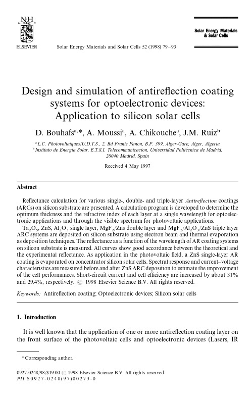
Solar Energy Materials and Solar Cells 52(1998)79—93Design and simulation of antireflection coatingsystems for optoelectronic devices:Application to silicon solar cellsD.Bouhafs *,A.Moussi ,A.Chikouche ,J.M.RuizL.C.Photo v oltaiques /U.D.T.S.,2,Bd Frantz Fanon,B.P.399,Alger-Gare,Alger,Algeria Instituto de Energia Solar,E.T.S.I.Telecommunicacion,Uni v ersidad Polite &cnica de Madrid,28040Madrid,SpainReceived 4May 1997AbstractReflectance calculation for various single-,double-and triple-layer Antireflection coatings (ARCs)on silicon substrate are presented.A calculation program is developed to determine the optimum thickness and the refractive index of each layer at a single wavelength for optoelec-tronic applications and through the visible spectrum for photovoltaic applications.Ta O ,ZnS,Al O single layer,MgF /Zns double layer and MgF /Al O/ZnS triple layer ARC systems are deposited on silicon substrate using electron beam and thermal evaporation as deposition techniques.The reflectance as a function of the wavelength of AR coating systems on silicon substrate is measured.All curves show good accordance between the theoretical and the experimental reflectance.As application in the photovoltaic field,a ZnS single-layer AR coating is evaporated on concentrator silicon solar cells.Spectral response and current —voltage characteristics are measured before and after ZnS ARC deposition to estimate the improvement of the cell performances.Short-circuit current and cell efficiency are increased by about 31%and 29.4%,respectively. 1998Elsevier Science B.V.All rights reserved.Keywords:Antireflection coating;Optoelectronic devices;Silicon solar cells1.IntroductionIt is well known that the application of one or more antireflection coating layer on the front surface of the photovoltaic cells and optoelectronic devices (Lasers,IR*Corresponding author.diodes,etc)reduces the amounted reflection of the incident light,which improves the device performance[1—5].Kern and Tracy[6]have observed an increase of observed an increase of about44%of the cell efficiency after spraying TiO single-layer ARC.Green et al.[7]have used MgF /ZnS two-layers on silicon cells with19.1%efficiency.The use,for silicon solar cells,of more than two layers ARCs in practice is limited.The theory of antireflection coating is examined by many authors[8—11]for determining the optimum thickness and materials to be used as ARCs on polished or textured silicon.The matrix method[11]is usually employed for calculation of reflection coefficient.In this paper,we present the result of calculations obtained by our computer programme of one-,two-and three-layer ARCs on silicon substrate.Theoretical results are shown in Section1The process of the cell fabrication is presented in Section2.In Section3we give the experimental measurements of optical and electrical characterisation and discussion about these results.2.TheoryDirect matrix method is used to evaluate the reflection coefficient of a multilayer system on silicon substrate.The system of N layers,Fig.1,is characterised by the equivalent matrix M ,which relates the amplitudes of electromagneticfield compo-nents at the(N th)interface with the incident electromagneticfield components. The equivalent matrix of N layers interlocked between two semi-infinite mediums is given in Ref.[12]M "H ,( cos H(i/n H)sin Hi n H sin H cos H (1)where i "!1,n H is the refractive index of j th layer, H is the phase thickness of j th layer, H"2 / n H d H,n H"n H cos H for parallel polarisation,n H"n H/cos H for 80 D.Bouhafs et al./Solar Energy Materials and Solar Cells52(1998)79—93Fig.1.A multilayer stack scheme of N layers on a semi-infinite substrate n .perpendicular polarisation and His the incident angle in the layer j .It is calculatedfrom the Snell’s law:n H \sin H \ "n H sinHMany different types of optoelectronic devices such as LASER and IR photo-diodesneed a very low reflectance at a defined wavelength ( )[13].The antireflection coating system (one layer or more)for each application are calculated for a minimum reflectance R ( ).Analytical or contour methods are generally used to determine the optimum parameters (n ,d )of the optical films.For photovoltaic cells it is important to have a minimum reflection over all the visible spectrum (300—1100nm).The cell performance is influenced by other para-meters such as the photon flux F ( )and the cell internal quantum efficiency Q G( )[1,8].Since the reflection coefficient needs to be minimised where F ( )and Q G( )havetheir maximum values,the weighted reflectance R Uis calculated from Ref.[8]:R 5" H H F ( )Q ( )R ( )dH H F ( )Q( )d.(2)Silicon substrate is considered absorptive and the dispersion law is taken intoaccount using data from Refs.[14,15].Materials used as ARCs are assumed to be transparent.Values of F ( )and Q( )used in the programme are extracted from[16,17]corresponding to the AM 1.5solar spectrum.Various methods have been used for the design of a multilayer optical thin film system [18—20].In this case,the contour method [17,22]is used for determining the optimal parameters.The refractive index n and thickness d are determined with the minimal weighted reflectance R .2.1.Single-layer ARC2.1.1.Single wa v elengthIn some applications (Laser,photodiodes etc.)zero reflectance is needed at a single wavelength or throughout a narrow spectrum band.For determining the optimum thickness and refractive index with a minimum reflectance,the following equations are deduced from Eq.(1):n "(n n !(n k )/(n !n )) ,(3)d "( /2 )arctg ([n (n !n )/(n k)],(4)where n is the refractive index of the incident medium,nthe refractive index of thesubstrate and kthe extinction coefficient of the substrate.For each wavelength wehave to calculate n and d which give R ( )"0from Eqs.(3)and (4),respectively.Fig.2shows the curves of the optimum values of n and d .D.Bouhafs et al./Solar Energy Materials and Solar Cells 52(1998)79—9381Fig.2.Optimum values of (n ,d )pairs vs.wavelength for a single antireflection coating on silicon.Each pair (n ,d )gives zero reflection at a definedwavelength.Fig.3.Reflectance spectra vs.wavelength for some optimised single-layer antireflection coating on silicon.Fig.3illustrates the reflectance spectra of three optimised single-layer ARC systems on silicon substrate.For a lower value of n ,a higher corresponding value of d is obtained (Eqs.(3)and (4))and we show that the minimum reflectance is shifted to the long-wavelength spectral region (Fig.3).82 D.Bouhafs et al./Solar Energy Materials and Solar Cells 52(1998)79—93Fig.4.Contours of weighted reflectance for a single-layer AR coating on silicon as a function of thickness and refractive index.2.1.2.UV-visible spectrumWeighted reflectance are calculated from Eq.(2)for determining the optimum values of n and d with Rminimum.Results are illustrated in Fig.4.The lowest valueR—6.2%is obtained with n "1.96,d "86nm.This value n "1.96can correspond to the TiO Vdeposited by spray [6]or to CeO by vacuum evaporation [2].Taking intoaccount experimental data [1,2,6]of materials used usually as AR coatings we have calculated some single-layer ARCs for silicon solar cells.From Table 1we show that the minimum of Ris higher than the optimised value due to fluctuation of therefractive index.2.2.Two-layer ARCs2.2.1.Single wa v elengthThe Schustter diagram [21]for silicon substrate is established to choose the optimum index of the inner and outer layers.A diagram in which n,the refractiveindex of the inner layer is plotted against n,the refractive index of the outer layer.Itillustrates the conditions which give a zero reflection:AB /CD '0whereA "n !n ,B "n n!n n ,C "n n!n ,D "n !n n ,For more details,Ref.[21]gives explicitly the different steps of calculations.D.Bouhafs et al./Solar Energy Materials and Solar Cells 52(1998)79—938384 D.Bouhafs et al./Solar Energy Materials and Solar Cells52(1998)79—93Table1Optimised single-layer AR coating on polished silicon substrateMaterial TiO (Spray)Ta O ZnS SiO Refractive index(n) 2.0 2.1 2.3 1.46 Thickness d(nm)82.080.068110 Weighted reflectance R %8.9910.711.77The design with low-high index on silicon substrate in which the outer layer has the low refractive index and the inner layer has high refractive index is used.This choice is based on the spectral stability of the coating and for low reflectance.Stability means that the low-reflectance spectrum changes very slightly with thickness and refractive index variations.Generally,the experimental conditions affect the thickness and refractive index values of the deposited layer and,consequently,the desired low reflectance value.Calculations show that the L—H design gives more advantage than the H—L design to keep the low reflectance value with the variations of n and d of each layer in the ARC system during deposition.The most stable coatings are those which have an inner layer whose refractive index is close to that of the substrate and the outer layer whose refractive index is close to that of the incident medium[23]. Fig.5shows the contours of equal reflectance R( )plotted against the thickness of both layers at "600nm.The minimum reflectance obtained is1;10\ (%)with d "55.5nm and d "53.2nm.The corresponding reflectance spectra of the opti-mised AR coating system are shown in Fig.6.One minimum appears at "600nm. Such AR coating systems are used in photodiodes(LASER)and other optoelectronicdevices which need a minimum reflectance spectra of the optimised AR coating system are shown in Fig.6.One minimum appears at "600nm.Such AR coating systems are used in photodiodes(LASER)and other optoelectronic devices which need a minimum reflectance at a single wavelength.2.2.2.UV-visible spectrumFor photovoltaic applications the reflectance is minimised through the visible spectrum.Fig.7shows the R contours in which appear the low value R "2.39%obtained with n "1.4,n "2.5,d "11.5nm,d "65nm.Table2illustrates the results of the calculated ARC systems with several existing materials such as MgF ,SiO ,Ta O and ZnS.The refractive index values n "1.4,n "2.5correspond to MgF and TiO deposited by evaporation techniques,respectively.We show(Table2)that a lower fluctuation in n causes a variation in the weighted reflectance coefficient R .This variation aided the optimum choice of the technological parameters of the technique to reduce thefluctuation commonly appearing during the deposition.Fig.5.Contours of weighted reflectance of SiO /TiO ARCs plotted against d1 -and d2 -at "600nm.Fig.6.Reflectance spectra vs.wavelength for SiO /TiO two-layer ARCs on silicon substrate. R ( )"1;10\ (%)at "600nm.2.3.Three-layer ARCsThe design of three-layer ARCs on silicon is optimised using Eq.(2)when the optimum refractive index of each layer in the stack is calculated by[5]:n "n .n "n .n ,D.Bouhafs et al./Solar Energy Materials and Solar Cells52(1998)79—9385Fig.7.Contours of weighted reflectance for two-layer ARCs on silicon as a function of the inner and the outer layer thickness (d ,d ).Table 2Optimum parameters of some two-layer AR coatings design on polished silicon substrate System (L,H)n n d (nm)d (nm)R (%)(1.41,2.24) 1.41 2.24112.069.0 2.65(1.5,2.0) 1.50 2.00072.560.0 6.23(1.5,2.1) 1.50 2.10071.561.0 6.25(1.5,2.5) 1.50 2.50098.061.5 2.98(1.4,2.0) 1.40 2.0093.570.0 5.32(1.4,2.1) 1.40 2.10078.568.5 4.77(1.4,2.5)1.402.5111.565.02.39where nis the refractive index of the medium layer.The refractive index decreasesfrom the high value (n )to the low value (n "1)in the order:n (n (n(n (n.Table 3shows the optimum values.We note that it is not possible to deposit materials with a refractive index n "2.78which does not absorb an appreciable86 D.Bouhafs et al./Solar Energy Materials and Solar Cells 52(1998)79—93Table3Optimum parameters of three-layer AR coatings design on polished silicon substrateAR coating design Layer parameters Outer layer Medium layer Inner layer Optimum calculateddesignRefractive index 1.40 1.97 2.78Thickness d(nm)1045551Weighted reflectance R (%) 1.4Calculated design withpractical materialsRefractive index 1.38 1.63 2.3Thickness d(nm)823354Weighted reflectance R (%)2.4Fig.8.n>pp>silicon solar cell structure with antireflection coating.amount of the incident light[2].Using materials deposited by vacuum evaporation such as ZnS(n"2.3—2.4),Al 0 (n"1.63)and MgF (n"1.38),three-layer ARC systems on silicon are calculated.Table3shows that R "2.4%is higher than the minimal value R "1.4%obtained with the optimum system.3.Experimental proceduren>pp>silicon solar cells are fabricated using a4—5 cm boron-doped single-crystal silicon wafers.Emitter region n>are realised by diffusing phosphorous atoms from a POCl liquid source.p>region(BSF)are formed by evaporating a thin layer of aluminium on the rear surface.Drive-in of P and Al atoms was carried in a quartz tube furnace simultaneously at850°C.Ti/Pd/Ag grid metallisation are evaporated on the front surface.The cell rear contact is realised by deposition of a thin layer of Al/Ag, Fig.8.Before AR coating,deposition cell performances are characterised at standard conditions(AM1.5,25°C).One-,two-and three-layer ARCs are deposited on silicon substrates in a stainless steel bell jar from a thermal tungsten crucible fro ZnS and by an electron gun for MgF ,Ta O ,Al O using a cleaned C and Mo crucibles.Pressure reached in deposit chamber is10\ —10\ torr.The deposition rate and the thickness of thefilms are controlled in situ by a quartz crystal monitor through an SCT200processor from SYCON Instruments.D.Bouhafs et al./Solar Energy Materials and Solar Cells52(1998)79—9387Fig.9.Measured and calculated reflectance of Ta OARC on silicon.Reflectance spectra was measured in the range 400—1100nm by a Spectro320Instrument Systems GmbH spectrophotometer.Current —voltage characteristic (I—»)and spectral response are measured for a sili-con solar cell with ZnS ARC to estimate the improvement in the cell’s performance after ARC deposition.Electrical characterisation are done at the ISPRA Laboratory,(Varese,Italy).4.Experimental results and discussionOptical measurements of the reflectance spectra of Ta OARC layer deposited onsilicon are shown in Fig.9.A minimum value of reflectance R ( )"0.1%is obtained at 650nm.Good agreement is observed between the experimental and calculated reflectance spectra.The refractive index and thickness used in the calculations are 2.1and 80nm,respectively.The difference observed in the short-and the long-wavelength regions is due to the dispersion of the Ta Orefractive index.The reflectance spectra of the ZnS ARC evaporated on silicon are shown in Fig.10.Good accordance is seen between the experimental and the calculated R ( )curve throughout the visible spectrum.We note that the ZnS layer is more transparent in the short wavelength region ( )500nm)than the Ta Olayer (Fig.9).I—»charac-teristic and spectral response of the cells indicate a good transparency of the ZnS layer in the short wavelength region.The absorption of the Ta Ois attributed to thepresence of excess free oxygen atoms in the deposited film,due probably to the dissociation of the Ta Omolecules during electron beam evaporation.Fig.11shows reflectance curve of MgF/ZnS two-layer ARC on which appear twominima:the first R "9.1%at 500nm,the second R"0.58%at 1000nm.The88 D.Bouhafs et al./Solar Energy Materials and Solar Cells 52(1998)79—93Fig.10.Measured and calculated spectral reflectance of ZnS ARC on silicon.Fig.11.Experimental and calculated reflectance vs.wavelength of MgF /ZnS two-layer ARC on silicon.Fig.12.Measured and calculated spectral reflectance of MgF /Al O /ZnS triple-layer ARCs on silicon.reflectance R( )is lower than3%in the range720nm) )1100nm which maxi-mises the absorption of the incident photons and increases the photo-generated current.On the basis of theoretical calculations[1,24],the reflectance value in the short wavelength region is affected by the outer layer(MgF )thickness for which the deposited thickness is estimated to be lower than the needed value(optimum). Fig.12shows the experimental reflectance of the MgF /Al O /ZnS three-layers on silicon.Two minima appear;R "5.8%at "500nm,R "0.88%at "1000nm.Through the range800—1100nm the reflectance is lower than3%.The curve R( )(Fig.12)is characterised by a broader low reflectance.Good accordance is observed between the calculated and the experimental curves.The difference in the short wavelength region is probably due to the dispersion of the refractive index in the wavelength region.Fig.13gives the current—voltage characteristics.It show the improvement of the short-circuit current and efficiency after ZnS and Ta O AR coating deposition.The I—»charactristic with a ZnS AR coating is better than that with Ta O ARC.Table4 shows the cell’s performance before and after ZnS AR coating.The short-circuit current and the cell efficiency show an increase of about31%and29.4%respectively. The open-circuit voltage» and thefill factor FF are not influenced by the ARC deposition;the slight variation observed could be attributed to the circuit measure-ment error.Fig.13.Silicon solar cell I—»characteristics before and after ZnS(d"52nm)and Ta O (80nm) single-layer antireflection coating.Table4Cell’s performace before and after ZnS coatingJ (mA/cm )FF(%)» (mV) %No AR coating28.30.79607.013.6 With ZnS AR coating37.10.767608.317.6We give Fig.14the spectral response Sr( )of the cell before and after a ZnS ARC deposition.The Sr( )is increased uniformly throughout the spectrum range.The curve shows a maximum in the long-wavelength region due to the back-surfacefieldeffect which reduces the recombination at the back side,therefore,decrease of theFig.14.Spectral response of silicon solar cell.(1)without AR coating;(2)with a ZnS single-layer AR coating(d"52nm).diode leakage current[25]and increase of the collection efficiency of the minority carries generated by the NIR photons.5.ConclusionsA theoretical study of the antireflection coatings on silicon solar cells is made.A model programme is developed for the best design of antireflection coating for an arbitrary substrate n and incident angle of light.Polished and textured silicon surfaces are taken into account.Our developed simulator can be used also for the optimisation of AR coating for optoelectronic devices to improve the power output parameters.One-,two-and three-layer ARCs on silicon are calculated at normal incidence.The optimum refractive index and thickness are determined.Ta O ,ZnS single-layer, MgF /ZnS two-layer and MgF /Al O /ZnS three-layer antireflection coatings are deposited by thermal and electron beam evaporation on silicon.Reflectance spectra of deposited ARC layers on silicon are measured.The theoret-ical and experimental R( )curves present a good accordance.Current—voltage charac-teristic and spectral response for a silicon solar cell with a ZnS ARC show an amelioration after antireflection deposition.Fill factor and open-circuit voltage areweakly influenced by the antireflection coating deposition.AcknowledgementsThis work was supported by the Unite de De vellopement de la Technologie du Silicium/Ministe re de l’Enseignement Superieur et de la Recherche Scientifique,Alger, and in part realised in the Instituto de Energia Solar,Madrid.References[1]G.E.Jellison Jr.,R.F.Wood,Solar Cells18(1986)93.[2]J.Zhao,M.A.Green,IEEE Trans.on Electronic Dev.38(8),1991.[3]P.A.Iles,J.Vac.Sci.Technol.14(1977)1100.[4]P.A.Young,W.G.Thege,J.Phys.D:Appl.Phys.4(1971)64.[5]J.Thomas Cox,Georg Hass,Antireflection coatings for optical and infrared optical materials,in:Physics of Thin Films Collec.,vol.2,Academic Press,New York,1964.[6]W.Kern,E.Tracy,RCA Review41(1980)133.[7]M.A.Green et al.,Appl.Phys.Lett.44(1984)1163.[8]D.Redfield,Solar Cells3(1981)27.[9]B.L.Sopori,R.A.Pryor,Solar Cells8(1983)249.[10]B.Gandham,et al.,Solar Cells1(1979/1980)3.[11]P.H.Berning,Theory and calculation of optical thinfilms,in:Physics of Thin Films Collec.,vol.1,Academic Press,New York,1963,p.69.[12]J.Mouchart,Appl.Optics16(9)(1977).[13]K.Rabinovitch,A.Pagis,Appl.Optics14(5)(1975).[14]G.E.Jellison,F.A.Modine,J.Appl.Phys.53(1982)3745.[15]Ed.Palik,Handbook of optical constants of solids,Academic Press,New York,1985.[16]R.H.Bube,Fundamental of solar cells,Academic Press,New York,1983.[17]R.B.Pettit,C.J.Brinker,C.S.Ashley,Solar Cells15(1985)267.[18]G.Castagno,F.Demichelis,E.Minetti-Mezzeti,Appl.Optics19(3)(1980).[19]L.Bloom,Appl.Optics20(1)(1981).[20]J.A.Dobrowolski,S.H.C.Piotrowski,Appl.Optics21(8)(1982).[21]B.A.Moys,Thin Solid Films21(1974)145.[22]M.E.Nell et al.,10th European Photovoltaic Solar Energy Conf.,8—12April,Lisbon,1991.[23]J.C.Monga,Some concepts for the design of grazing incidence antireflection coating,Science Report,Bhabha Atomic Research Center,Bombay,India,1992.[24]D.Bouhafs,These de magister,L.C.P./U.D.T.S.Alger,1993.[25]K.L.Jiao,W.A.Anderson,Solar Cells22(1987)229.。

江苏省太阳能资源评估曾燕;王珂清;谢志清;苗茜【摘要】采用1:25万DEM数据和常规气象站观测资料,实现了江苏省100mX100m分辨率太阳总辐射量分布式模拟,并分析了江苏省太阳总辐射量的时空分布规律。
结果表明:江苏省气候平均太阳总辐射量为4749MJ/m2,呈现由西南向东北递增的特点,连云港市最高(5063MJ/m2),无锡市最低(4514MJ/m2)。
太阳总辐射量在年内变化特点为,5月最高,12月最低。
结合常规气象站日照时数观测资料,从年日照时数、年日照时数i〉6h的天数以及日照时数〉16h的最多天数月份与最少天数月份的天数的比值分析了江苏省太阳能资源的稳定度特征,其总体规律依然是西南至东北走向,即江苏省东北部地区太阳能资源开发利用优势最高。
%Using the data of DEM with scale of 1 : 250 000 and routine meteorological observations, this paper achieves the distributed simulation of global solar radiation (GSR) of Jiangsu Province. Spatial distribution maps of normals of monthly and annual GSR with the resolution of 100 m x 100 m of Jiangsu Province are generated and their spatioemporal distribution characteristics are analyzed. The results are as follows: 1 )The normals of annual GSR in Jiangsu Province is 4 749MJ/m2 ;2)The annual GSR has a progressive increasing trend from southwest to northeast, i. e. Lianyungang has the highest value of 5 063 MJ/m2 and Wuxi the lowest value of 4 514 MJ/m2 ;3 ) GSR in Jiangsu Province reaches the highest in May and the lowest in December. The statistics of sunshine hours observations, i. e. annual sunshine hours, annual days with daily sunshine hours I〉6 h and the ratio of the maximumto the minimum of monthly days with daily sunshine hours I〉6 h, are used to analyze the stability of solar radiation resource in Jiangsu. Its pattern also has a southwest to northeast change trend, which is to say that the northeast region of Jiangsu has the highest predominance in solar energy utilizing.【期刊名称】《大气科学学报》【年(卷),期】2012(035)006【总页数】6页(P658-663)【关键词】江苏省;太阳总辐射;太阳能;资源评估【作者】曾燕;王珂清;谢志清;苗茜【作者单位】江苏省气候中心,江苏南京210008;江苏省气候中心,江苏南京210008;江苏省气候中心,江苏南京210008;江苏省气候中心,江苏南京210008【正文语种】中文【中图分类】P422.1太阳能资源是一种取之不尽、用之不竭的绿色能源。

基于RT-LAB的光伏发电系统实时仿真郑鹤玲;葛宝明;毕大强【摘要】本文利用光伏模拟器代替传统的光伏电池,建立单级式光伏发电系统,在RT-LAB仿真平台中搭建了实时仿真模型,对系统进行了仿真研究.该实验平台克服了实物系统受光照与温度现实条件的限制, 同时可以兼顾硬件环境对实验的影响 ,弥补了全数字仿真的不足,为实验室内进行大功率的光伏系统实验提供了一个良好的平台.【期刊名称】《电工电能新技术》【年(卷),期】2010(029)004【总页数】5页(P62-66)【关键词】光伏模拟器;单级式光伏并网系统;RT-LAB;实时仿真【作者】郑鹤玲;葛宝明;毕大强【作者单位】北京交通大学电气工程学院,北京,100044;北京交通大学电气工程学院,北京,100044;电力系统国家重点实验室,清华大学电机系,北京,100084【正文语种】中文【中图分类】TM615引言随着传统能源的日益枯竭,太阳能已经成为一种十分重要的新能源,而当前开发利用太阳能的主要方式是光伏发电[1],相关研究日益深入[2,3]。
对于光伏发电系统而言,其中最主要的问题是如何提高系统的发电效率以及整个系统的工作稳定性[4],目前我国的光伏发电水平相对于发达国家尚有一定差距,仍需要投入大量的研究。
在进行真实系统的实验时,不仅成本高,而且受制于日射强度、环境温度等自然条件的限制,大多数情况下难以如愿达到预期的试验与测量效果。
如采用全数字仿真平台进行研究时,则完全脱离了对硬件的依赖,严重脱离现实,过于理想。
如果在实验室内利用先进的实时仿真软件,结合硬件在回路技术,搭建半实物仿真平台,则可以很好地解决这个矛盾。
目前,建立仿真测试平台的工具主要有 ADS-Ⅱ、EuroSim、dSPACE、RT-LAB 等。
ADS-Ⅱ为分布式实时系统,必须在仿真前准备大量数据文件,不支持仿真过程的在线参数修改;EuroSim运行于Unix、Linux或者Windows NT操作系统下,难于开发专用板卡驱动程序;dSPACE可应用于从系统建模、分析、离线仿真到实时仿真的全过程,不足之处在于扩充仿真系统必须选择其公司配套出品的处理器板卡,灵活性差;RT-LAB支持多种工业标准,可与MATLAB/Simulink、MATRIXx/Systembuild 无缝连接,可结合具体硬件对控制器进行优化,使用灵活,并具有在仿真过程中可在线调参,便于逆向测试等优点。

论文收录检索证明报告华北电力大学图书馆论文作者: Xu Chao论文发表年限: 2006--检索数据库: SCI-Expanded检索结果:经检索,该作者被SCI-Expanded数据库收录篇论文(附后)。
在篇收录文献中,其中篇文献被“Web of Science 数据库”引用,总被引次数(Time cited)为次;被“Web of Science 核心合集”引用次。
其中他引次。
(篇引用文献题录附后)。
特此证明!(盖章)检索报告人:年月日附件: SCI-Expanded收录及引用情况第1 条,共6 条标题: Numerical simulation on the thermal performance of a solar molten salt cavity receiver作者: Chang, ZS (Chang, Zheshao); Li, X (Li, Xin); Xu, C (Xu, Chao); Chang, C (Chang, Chun); Wang, ZF (Wang, Zhifeng)来源出版物: RENEWABLE ENERGY 卷: 69 页: 324-335 DOI:10.1016/j.renene.2014.03.044 出版年: SEP 2014Web of Science 核心合集中的"被引频次": 1被引频次合计: 1引用的参考文献数: 29摘要: The receiver thermal performance directly affects the efficiency, reliability and safety of the entire solar tower power system. A model combining radiation, convection and conduction heat transfer modes was developed to model a 1 MW molten salt cavity receiver with determined basic design parameters. The coupled heat transfer model was used to predict the receiver's steady-state efficiency, temperature distribution and heat losses for various flow layouts and receiver aperture lip sizes.The results show that the fraction of reflective loss (18.78%) is the largest in all heat losses, followed by radiative and convective heat losses, with conduction heat losses as the smallest part which is usually negligible. The heat loss distribution is closely related to the external tube temperature field in the cavity receiver and the specific structure of the receiver. 10 cm lips on both the top and bottom of the receiver aperture reduced the reflective heat loss by 1%. The results for different flow layouts show that center-side flow layout has the best temperature homogeneity, with less possibility of overheating in the central area. This, however, comes at the expense of increased irreversibilities and decreased efficiency. The sides-center flow layout has the worst temperature homogeneity, but the receiver efficiency is 2.06% higher. These results provide a useful reference for designing and optimizing cavity receivers. (C) 2014 Elsevier Ltd. All rights reserved.入藏号: WOS:000338802400036语种: English文献类型: Article作者关键词: Solar cavity receiver; Simulation; Thermal performance; Flow layout KeyWords Plus: CONVECTION HEAT-LOSS; NATURAL-CONVECTION; RADIATION; CONCENTRATOR; LOSSES; PLANT; MODEL地址: [Chang, Zheshao; Li, Xin; Chang, Chun; Wang, Zhifeng] Chinese Acad Sci, Inst Elect Engn, Key Lab Solar Thermal Energy & Photovolta Syst, Beijing 100190, Peoples R China. [Chang, Zheshao] Univ Chinese Acad Sci, Beijing 100049, Peoples R China.[Xu, Chao] North China Elect Power Univ, Beijing 100190, Peoples R China.通讯作者地址: Li, X (通讯作者),Chinese Acad Sci, Inst Elect Engn, Key Lab Solar Thermal Energy & Photovolta Syst, Beijing 100190, Peoples R China.电子邮件地址: drlixin@作者识别号:作者ResearcherID 号ORCID 号Li, XinA-2059-20130000-0002-0640-6939Xu, ChaoC-6470-2008出版商: PERGAMON-ELSEVIER SCIENCE LTD出版商地址: THE BOULEVARD, LANGFORD LANE, KIDLINGTON, OXFORD OX5 1GB, ENGLANDWeb of Science 类别: Energy & Fuels研究方向: Energy & FuelsIDS 号: AL0FIISSN: 0960-148129 字符的来源出版物名称缩写: RENEW ENERGISO 来源出版物缩写: Renew. Energy来源出版物页码计数: 12施引文献:第1 条,共1 条标题: Experimental investigation on heat loss of semi-spherical cavity receiver作者: Tan, YT (Tan, Yuting); Zhao, L (Zhao, Li); Bao, JJ (Bao, Junjiang); Liu, Q (Liu, Qing) 来源出版物: ENERGY CONVERSION AND MANAGEMENT 卷: 87 页: 576-583 DOI: 10.1016/j.enconman.2014.06.080 出版年: NOV 2014入藏号: WOS:000343337200059ISSN: 0196-8904eISSN: 1879-2227第2 条,共6 条标题: Dynamic thermal performance analysis of a molten-salt packed-bed thermal energy storage system using PCM capsules作者: Wu, M (Wu, Ming); Xu, C (Xu, Chao); He, YL (He, Ya-Ling)来源出版物: APPLIED ENERGY 卷: 121 页: 184-195 DOI:10.1016/j.apenergy.2014.01.085 出版年: MAY 15 2014Web of Science 核心合集中的"被引频次": 2被引频次合计: 2引用的参考文献数: 27摘要: We investigate the dynamic thermal performance of a molten-salt packed-bed thermal energy storage (TES) system using capsules filled with high-temperature phase change material (PCM), which is identified as a promising low-cost TES system for concentrating solar power (CSP) plants. A transient two-dimensional dispersion-concentric (D-C) model is modified to account for the phase change process within capsules so as to determine the temperature distribution and phase change front within each capsule. Usingthe model, detailed characteristics of heat transfer between molten salt and the packed PCM capsules are investigated, and a parametric sensitivity analysis is provided. During the discharging process, different variation trends are found for the capsule temperature due to the existence of the isothermal solidification process. As a result, generally there exists a quasi-isothermal region and two thermocline regions for the molten-salt temperature along the tank height, and the molten-salt temperature at the outlet also shows a quasi-isothermal period, during which the molten-salt outlet temperature is very close to the phase change temperature (PCT) of PCM. It is also found that the effective discharging efficiency of the system can be increased by increasing the PCT, decreasing the molten-salt inlet velocity or decreasing the capsule diameter. These results provide suggestions to optimize the design and operational parameters for the system within practical constrains. (C) 2014 Elsevier Ltd. All rights reserved.入藏号: WOS:000335429500018语种: English文献类型: Article作者关键词: PCM capsules; Thermal energy storage; Thermocline; Packed-bed; Molten saltKeyWords Plus: LATENT-HEAT STORAGE; PHASE-CHANGE MATERIALS; THERMOCLINES; SIMULATIONS地址: [Wu, Ming; He, Ya-Ling] Xi An Jiao Tong Univ, Key Lab Thermofluid Sci & Engn MOE, Sch Energy & Power Engn, Xian 710049, Shaanxi, Peoples R China.[Xu, Chao] North China Elect Power Univ, Key Lab Condit Monitoring & Control Power Plant E, Sch Energy Power & Mech Engn, Beijing 102206, Peoples R China.通讯作者地址: He, YL (通讯作者),Xi An Jiao Tong Univ, Key Lab Thermofluid Sci & Engn MOE, Sch Energy & Power Engn, Xian 710049, Shaanxi, Peoples R China.电子邮件地址: yalinghe@作者识别号:作者ResearcherID 号ORCID 号Xu, ChaoC-6470-2008出版商: ELSEVIER SCI LTD出版商地址: THE BOULEVARD, LANGFORD LANE, KIDLINGTON, OXFORD OX5 1GB, OXON, ENGLANDWeb of Science 类别: Energy & Fuels; Engineering, Chemical研究方向: Energy & Fuels; EngineeringIDS 号: AG4ZSISSN: 0306-2619eISSN: 1872-911829 字符的来源出版物名称缩写: APPL ENERGISO 来源出版物缩写: Appl. Energy来源出版物页码计数: 12施引文献:第1 条,共2 条标题: An effectiveness-NTU model of a packed bed PCM thermal storage system作者: Amin, NAM (Amin, N. A. M.); Belusko, M (Belusko, M.); Bruno, F (Bruno, F.)来源出版物: APPLIED ENERGY 卷: 134 页: 356-362 DOI:10.1016/j.apenergy.2014.08.020 出版年: DEC 1 2014入藏号: WOS:000343336600034作者识别号:作者ResearcherID 号ORCID 号Bruno, FrankA-4840-20100000-0002-1805-0036ISSN: 0306-2619eISSN: 1872-9118第2 条,共2 条标题: An entransy dissipation-based optimization principle for solar power tower plants作者: Zheng, ZJ (Zheng ZhangJing); He, YL (He YaLing); Li, YS (Li YinShi)来源出版物: SCIENCE CHINA-TECHNOLOGICAL SCIENCES 卷: 57 期: 4 页:773-783 DOI: 10.1007/s11431-014-5491-7 出版年: APR 2014入藏号: WOS:000334400500017作者识别号:作者ResearcherID 号ORCID 号Li, Y.S.O-6839-2014ISSN: 1674-7321eISSN: 1869-1900第3 条,共6 条标题: Phase change of molten salt during the cold filling of a receiver tube作者: Liao, ZR (Liao, Zhirong); Li, X (Li, Xin); Wang, ZF (Wang, Zhifeng); Chang, C (Chang, Chun); Xu, C (Xu, Chao)来源出版物: SOLAR ENERGY 卷: 101 页: 254-264 DOI:10.1016/j.solener.2014.01.002 出版年: MAR 2014Web of Science 核心合集中的"被引频次": 0被引频次合计: 0引用的参考文献数: 27摘要: The most critical problems for the molten salt solar power plant are protecting against freezing and preheating of the flow pipes and equipments. A candidate way to solve these problems is cold filling. In this study, the dynamic process of molten salt cold filling into areceiver tube was simulated by combining the volume of fluid method and the enthalpy method. The detailed mechanism of meltingsolidification and the evolution of the pressure drop along the tube were demonstrated. The influence of cold filling on the temperature across the tube wall was analysed as well. The results indicate that a lower pressure drop can be obtained by increasing the salt temperature and the initial tube temperature, and that an optimal velocity is required to get minimum pressure drop. The temperature difference between the external and internal surfaces of the tube wall increases with the filling velocity and the filling temperature whereas decreases with the initial tube temperature and the heat flux on the external surface. A large filling velocity and a high filling temperature that results in large temperature difference across the wall of the tube should be avoided. This study gives practical reference to the application of cold filling in molten salt receiver. (C) 2014 Elsevier Ltd. All rights reserved.入藏号: WOS:000331921800026语种: English文献类型: Article作者关键词: Molten salt; Cold filling; Numerical simulation; Solar power tower plant KeyWords Plus: PIPE; SOLIDIFICATION地址: [Liao, Zhirong; Li, Xin; Wang, Zhifeng; Chang, Chun] Chinese Acad Sci, Inst Elect Engn, Key Lab Solar Thermal Energy & Photovolta Syst, Beijing 100190, Peoples R China. [Liao, Zhirong] Univ Chinese Acad Sci, Beijing 100049, Peoples R China.[Xu, Chao] North China Elect Power Univ, Beijing 102206, Peoples R China.通讯作者地址: Li, X (通讯作者),Chinese Acad Sci, Inst Elect Engn, Key Lab Solar Thermal Energy & Photovolta Syst, Beijing 100190, Peoples R China.电子邮件地址: drlixin@作者识别号:作者ResearcherID 号ORCID 号Li, XinA-2059-20130000-0002-0640-6939Xu, ChaoC-6470-2008出版商: PERGAMON-ELSEVIER SCIENCE LTD出版商地址: THE BOULEVARD, LANGFORD LANE, KIDLINGTON, OXFORD OX5 1GB, ENGLANDWeb of Science 类别: Energy & Fuels研究方向: Energy & FuelsIDS 号: AB6TGISSN: 0038-092X29 字符的来源出版物名称缩写: SOL ENERGYISO 来源出版物缩写: Sol. Energy来源出版物页码计数: 11第4 条,共6 条标题: Allowable flux density on a solar central receiver作者: Liao, ZR (Liao, Zhirong); Li, X (Li, Xin); Xu, C (Xu, Chao); Chang, C (Chang, Chun); Wang, ZF (Wang, Zhifeng)来源出版物: RENEWABLE ENERGY 卷: 62 页: 747-753 DOI:10.1016/j.renene.2013.08.044 出版年: FEB 2014Web of Science 核心合集中的"被引频次": 1被引频次合计: 1引用的参考文献数: 27摘要: The allowable flux density on a solar central receiver is a significant receiver parameter and is related to the receiver life span and economics. The allowable flux density has gradually increased as receiver technologies have developed and is related to various factors, such as the material characteristics, tube sizes, and internal tube flow conditions. A mathematical model was developed to calculate the allowable flux density for the Solar Two receiver which agrees well with published data. The model was then used to show that a higher allowable flux density can be obtained by increasing the allowable strain of the tube material and the fluid velocity and decreasing the tube thermal resistance, the convective thermal resistance, and the tube diameter and wall thickness. A sensitive analysis shows that the most important influence is the wall thickness, followed by the tube diameter and fluid velocity. Finally, a molten salt receiver gives a much higher allowable flux density than water/steam receivers and is even better than a supercritical steam receiver. (C) 2013 Elsevier Ltd. All rights reserved.入藏号: WOS:000328095000081语种: English文献类型: Article作者关键词: Allowable flux density; Central receiver; Molten salt; Solar power KeyWords Plus: THERMAL POWER TOWER; SIMULATION; PLANT地址: [Liao, Zhirong; Li, Xin; Chang, Chun; Wang, Zhifeng] Chinese Acad Sci, Inst Elect Engn, Key Lab Solar Thermal Energy & Photovolta Syst, Beijing 100190, Peoples R China. [Liao, Zhirong] Univ Chinese Acad Sci, Beijing 100049, Peoples R China.[Xu, Chao] North China Elect Power Univ, Beijing 102206, Peoples R China.通讯作者地址: Li, X (通讯作者),Chinese Acad Sci, Inst Elect Engn, Key Lab Solar Thermal Energy & Photovolta Syst, Beijing 100190, Peoples R China.电子邮件地址: drlixin@作者识别号:作者ResearcherID 号ORCID 号Li, XinA-2059-20130000-0002-0640-6939Xu, ChaoC-6470-2008出版商: PERGAMON-ELSEVIER SCIENCE LTD出版商地址: THE BOULEVARD, LANGFORD LANE, KIDLINGTON, OXFORD OX5 1GB, ENGLANDWeb of Science 类别: Energy & Fuels研究方向: Energy & FuelsIDS 号: 267JXISSN: 0960-148129 字符的来源出版物名称缩写: RENEW ENERGISO 来源出版物缩写: Renew. Energy来源出版物页码计数: 7施引文献:第1 条,共1 条标题: Thermal design guidelines of solar power towers作者: Rodriguez-Sanchez, MR (Rodriguez-Sanchez, M. R.); Soria-Verdugo, A(Soria-Verdugo, Antonio); Almendros-Ibanez, JA (Antonio Almendros-Ibanez, Jose); Acosta-Iborra, A (Acosta-Iborra, Antonio); Santana, D (Santana, Domingo)来源出版物: APPLIED THERMAL ENGINEERING 卷: 63 期: 1 页: 428-438 DOI:10.1016/j.applthermaleng.2013.11.014 出版年: FEB 5 2014入藏号: WOS:000331021600044作者识别号:作者ResearcherID 号ORCID 号Almendros-Ibanez, JoseB-6187-20090000-0001-5991-9028ISSN: 1359-4311第5 条,共6 条标题: The impact of concrete structure on the thermal performance of the dual-media thermocline thermal storage tank using concrete as the solid medium作者: Wu, M (Wu, Ming); Li, MJ (Li, Mingjia); Xu, C (Xu, Chao); He, YL (He, Yaling); Tao, WQ (Tao, Wenquan)来源出版物: APPLIED ENERGY 卷: 113 特刊: SI 页: 1363-1371 DOI:10.1016/j.apenergy.2013.08.044 出版年: JAN 2014Web of Science 核心合集中的"被引频次": 3被引频次合计: 3引用的参考文献数: 24摘要: The impact of concrete structure on the thermal performance of the dual-media thermocline thermal energy storage (TES) tank which is very promising to be applied in concentrating solar power (CSP) systems is investigated. The lumped capacitance method is used since the introduction of corrected heat transfer coefficients between solid and fluid extends the validity of this method to large Biot numbers. The discharging performance of four typical concrete structures including the channel-embedded structure, theparallel-plate structure, the rod-buddle structure and the packed-bed structure is studied. The thermocline behaviors during the discharging process for the four structures with the influences of feature size and fluid inlet velocity are analyzed, and the corresponding effective discharging efficiency and discharging time are reported. The results show that the concrete TES tanks with four different structures show different thermocline behaviors during the discharging process. The packed-bed structure gives the best discharging performance, followed by the rod-bundle structure, the parallel-plate structure and the channel-embedded structure sequentially. The discharging performance is also found to be influenced to some extent by the feature size and the fluid inlet velocity for all four different structures. (C) 2013 Elsevier Ltd. All rights reserved.入藏号: WOS:000329952500131语种: English文献类型: Article作者关键词: Concrete; Thermal energy storage; Thermocline; Concrete structures; Concentrating solar powerKeyWords Plus: MOLTEN-SALT THERMOCLINE; ENERGY STORAGE; SYSTEM地址: [Wu, Ming; Li, Mingjia; He, Yaling; Tao, Wenquan] Xi An Jiao Tong Univ, Key Lab Thermofluid Sci & Engn MOE, Sch Energy & Power Engn, Xian 710049, Shaanxi, Peoples R China.[Xu, Chao] North China Elect Power Univ, Key Lab Condit Monitoring & Control Power Plant E, Beijing 102206, Peoples R China.通讯作者地址: He, YL (通讯作者),Xi An Jiao Tong Univ, Key Lab Thermofluid Sci & Engn MOE, Sch Energy & Power Engn, Xian 710049, Shaanxi, Peoples R China.电子邮件地址: yalinghe@作者识别号:作者ResearcherID 号ORCID 号Xu, ChaoC-6470-2008出版商: ELSEVIER SCI LTD出版商地址: THE BOULEVARD, LANGFORD LANE, KIDLINGTON, OXFORD OX5 1GB, OXON, ENGLANDWeb of Science 类别: Energy & Fuels; Engineering, Chemical研究方向: Energy & Fuels; EngineeringIDS 号: 293DVISSN: 0306-2619eISSN: 1872-911829 字符的来源出版物名称缩写: APPL ENERGISO 来源出版物缩写: Appl. Energy来源出版物页码计数: 9施引文献:第1 条,共3 条标题: Dynamic thermal performance analysis of a molten-salt packed-bed thermal energy storage system using PCM capsules作者: Wu, M (Wu, Ming); Xu, C (Xu, Chao); He, YL (He, Ya-Ling)来源出版物: APPLIED ENERGY 卷: 121 页: 184-195 DOI:10.1016/j.apenergy.2014.01.085 出版年: MAY 15 2014入藏号: WOS:000335429500018作者识别号:作者ResearcherID 号ORCID 号Xu, ChaoC-6470-2008ISSN: 0306-2619eISSN: 1872-9118第2 条,共3 条标题: Experimental results and modeling of energy storage and recovery in a packed bed of alumina particles作者: Anderson, R (Anderson, Ryan); Shiri, S (Shiri, Samira); Bindra, H (Bindra, Hitesh); Morris, JF (Morris, Jeffrey F.)来源出版物: APPLIED ENERGY 卷: 119 页: 521-529 DOI:10.1016/j.apenergy.2014.01.030 出版年: APR 15 2014入藏号: WOS:000333506900048ISSN: 0306-2619eISSN: 1872-9118第3 条,共3 条标题: An entransy dissipation-based optimization principle for solar power tower plants作者: Zheng, ZJ (Zheng ZhangJing); He, YL (He YaLing); Li, YS (Li YinShi)来源出版物: SCIENCE CHINA-TECHNOLOGICAL SCIENCES 卷: 57 期: 4 页:773-783 DOI: 10.1007/s11431-014-5491-7 出版年: APR 2014入藏号: WOS:000334400500017作者识别号:作者ResearcherID 号ORCID 号Li, Y.S.O-6839-2014ISSN: 1674-7321eISSN: 1869-1900第6 条,共6 条标题: EXPERIMENTAL AND NUMERICAL STUDY OF HEAT TRANSFER OVER A FINNED ELLIPTICAL FLAT TUBE FITTED WITH LONGITUDINAL VORTEX GENERATORS ON THE RECTANGULAR FIN SURFACE作者: Li, L (Li, Li); Du, XZ (Du, Xiaoze); Zhang, YW (Zhang, Yuwen); Xu, C (Xu, Chao); Yang, LJ (Yang, Lijun); Yang, YP (Yang, Yongping)来源出版物: JOURNAL OF ENHANCED HEAT TRANSFER 卷: 20 期: 5 页: 427-441 出版年: 2013Web of Science 核心合集中的"被引频次": 0被引频次合计: 0引用的参考文献数: 34摘要: An experimental study of heat transfer over a finned elliptical flat tube fitted with and without longitudinal vortex generators (LVGs) mounted on the rectangular fins was carried out in a wind channel. Numerical simulation was performed to compare the experimental results and to verify the turbulence model. The test models were magnified four times greater than the original react model and correspondingly simplified according to the principle of similitude. Several fins were designed to construct the periodic boundary condition. Thermo couples were used to measure the temperatures on the fins and tube of the flow and surfaces. The experimental results showed that in the low Reynolds number regime, the heat transfer decreased continually from the entrance along the stream wise direction. However, in the high Reynolds number regime, the heat transfer had a maximum value in the middle points of the fins along the stream wise direction. It was demonstrated through the numerical simulation and experimental results that the configuration of the fin and tube with the LVGs on the fins could attain enhanced heat transfer without too much pressure drop.入藏号: WOS:000345612600005语种: English文献类型: Article作者关键词: extended surface; displaced enhancement device; compound enhancement; single-phase flow; vortex generatorsKeyWords Plus: TRANSFER ENHANCEMENT; DELTA-WINGLET; TURBULENT FLOWS; PRESSURE-DROP; OVAL TUBE; EXCHANGERS; VORTICES; CHANNEL; LAMINAR; PERFORMANCE地址: [Li, Li; Du, Xiaoze; Xu, Chao; Yang, Lijun; Yang, Yongping] North China Elect Power Univ, MOE Key Lab Condit Monitoring & Control Power Pla, Beijing 102206, Peoples R China.[Zhang, Yuwen] Univ Missouri, Dept Mech & Aerosp Engn, Columbia, MO 65211 USA.通讯作者地址: Li, L (通讯作者),North China Elect Power Univ, MOE Key Lab Condit Monitoring & Control Power Pla, Beijing 102206, Peoples R China.电子邮件地址: doubleli@作者识别号:作者ResearcherID 号ORCID 号Zhang, YuwenC-6474-20080000-0001-8915-1769出版商: BEGELL HOUSE INC出版商地址: 50 CROSS HIGHWAY, REDDING, CT 06896 USA Web of Science 类别: Thermodynamics; Engineering, Mechanical 研究方向: Thermodynamics; EngineeringIDS 号: AU4XUISSN: 1065-5131eISSN: 1563-507429 字符的来源出版物名称缩写: J ENHANC HEAT TRANSFISO 来源出版物缩写: J. Enhanc. Heat Transf.来源出版物页码计数: 15。

大气辐射校正模型简介1、acorn模型它是一种基于图像自身的大气校正软件,可以实现图像辐射值到表观地表反射率的转换,其工作的波长范围是350-2500nm。
在目前的大气校正程序一般都把地表假定为水平朗伯体,这主要是因为我们一般很难获取地表的充足信息以完成地形校正,因此大气校正的结果称为拉伸的地表反射率,又称表观反射率,在地形信息已知的情况下,可以将表观反射率转为地表反射率。
Acorn所提供的最高级的大气校正形式是基于辐射传输理论的,大气校正的方法是基于chandrasekhar(1960,dover)公式,描述了太阳辐射源、大气、和地表对辐射的贡献关系。
Caorn提供了一系列大气校正策略,包括经验法和基于辐射传输理论的方法,既可以对高光谱数据进行大气校正,也可以对多光谱图像数据进行大气校正,校正模式如下:1)模式1:对定标后的高光谱数据进行辐射传输大气校正,输出项为地表表观反射率。
2)模式1.5:对定标后的高光谱数据利用水气和液体水光谱你和技术进行辐射传输大气校正。
3)模式2:对高光谱大气校正结果进行独立的光谱增强。
4)模式3:利用经验线性法对高光谱数据进行大气校正5)模式4:对高光谱数据进行卷积处理得到多光谱数据6)模式5:对定标的多光谱数据进行辐射传输大气校正7)模式6:对多光谱的大气校正结果进行独立的光谱增强2、lowtran模型LOWTRAN是一种低分辨率(分辨率≥20cm-1)大气辐射传输模式。
它提供了6种参考大气模式的温度、气压、密度的垂直廓线,水汽、臭氧、甲烷、一氧化碳、一氧化二氮的混合比垂直廓线,其他13种微量气体的垂直廓线,城乡大气气溶胶、雾、沙尘、火山喷发物、云、雨的廓线,辐射参量(如消光系数、吸收系数、非对称因子的光谱分布),以及地外太阳光谱。
lowtran7可以根据用户的需要,设置水平、倾斜、及垂直路径,地对空、空对地等各种探测几何形式,适用对象广泛。
lowtran7的基本算法包括透过率计算方法,多次散射处理和几何路径计算。
Assignment for solar thermal conversion (No.1)This problem involves calculations on four surface: (1) vertical west-facing; (2) vertical north-facing; (3) vertical south –facing; and (4) horizontal. The results you will generate are common intermediate calculations in energy-conscious building design. (A vertical east-facing surface is omitted due to symmetry with the corresponding west-facing wall.) All calculations are to be performed for two dates:(1)21 December; (2) 21 June;and for two times of day:(a) 10:00; and (b) 13:00 local clock time (not solar time and you need to convert from local clock time to solar time).The location is Kunming of China, latitude=25.01oN, longitude=102.7oE(A)Calculate the cosine of the incidence angle for each of the four surfaces, at two different times of day, for each of the two dates (altogether 16 calculations)(B)Calculate the sunrise/sunset hour (in solar time) on each of the four surfaces for each of the two dates.(C)Calculate the daily total extraterrestrial radiation (in MJ/m 2) for each of the four surfaces,for each of two dates. (Be careful, in your calculations, to use the sunrise/sunset hour on the surfaces themselves, and be careful to use the correct unit of time and hour angle).Assignment for Solar Thermal Conversion (No.2)1. The knowledge of the tilt and azimuth for a tracking solar collector is often essential in system design. For example, programming the microprocessor that controls the tracking requires an algorithm for the rate at which the collector must move for each minute of the day and each day of the year. Another example is tracking flat-plate photovoltaic systems. The collector tilt angle depends on time of day and day of year. This is important in the calculation of collectible energy since the collectible diffuse and ground-reflected radiation both depend on collector tilt angle.For the following tracking modes, derive expressions for both the collector tilt and the collector azimuth as function of: hour angle , s olar declination angle , and latitude .(a)horizontal east-west axis tracking;(b)horizontal north-south axis tracking;(c)polar axis tracking; and(d)two-axis tracking.[Hint: In some instances, a little bit of thinking about the physical picture can save hours of messy algebra]2. Buildings are not always oriented towards due south or north, and in such case, it is necessary to do exchange of coordinate systems for designing the overhang of a south-facing window. Here is a practical design: a building is located in Kunming with the south wall oriented towards 30 west from south. Please(a)derive the expression of projected angle of solar rays on the plane perpendicular to horizontal and the south wall as a function of hour angle , sola r declination angle , latitude and azimuth angle of the south wall through coordinates exchange.(b)Supposing the height of the window is h, how to design the overhang that makes the window completely shaded at 13:30 PM (solar time) from 21 May to 21 July of the year, and makes the window completely exposed to the sun from 21 Oct. to 21 Feb.Assignment for Solar Energy Thermal Conversion (No.:3)Solar gain through windows is essential to predict thermal performance of a building, and this exercise is concerned with the calculation of solar heat gain through a single or double glazed window. Assuming the window glass is 3 mm in thickness and its extinctioncoefficient k=40 m -1, refractive index n=1.5.(1)Derive expressions of solar transmittance through a single-glass and a double-glasses window; Plot curves of solar transmittance through both single-glass and double-glasses windows vs. the incidence angle.(2)Calculate the equivalent transmittance for diffuse radiation through both windows.(3)If the windows are installed at south wall of a building located at Kunming (01.25 ). Themonthly hemispheric radiation on January in Kunming is Hh =396 MJ/m2. Please plot (a):solar radiation falling on windows vs. time of the day (representative day); (b): solar radiation through a single-glass window; (c) solar radiation through a double-glasses window.(4)Calculate the daily collectible solar radiation on windows and the daily solar heat gain of the buildings with a single-glass and a double-glasses windowAssignment for Solar Thermal Conversion (No:4)Design an ideal CPC (2D) with a half acceptance angle a and a two -sided vertical flat plate absorber (assuming the height of the absorber is a)1: please plot the full CPC by the use of string method and describe the procedure of drawing such a CPC.2: present the equations of reflectors3: if the CPC is truncated with extreme accepted angle t , derive the expressions of C t , H tand accepted energy fraction of incident energy F().Assignment of Solar thermal conversion (No.5)1.Design an ideal two-dimension CPC. The concentrator is west-east aligned with the tilt angle of the aperture being site latitude. For such device, the projection angle of sunlight on the plane perpendicular to the concentrator axis is a crucial parameter determining whether the direct sunlight is accepted.(a)derive the mathematical express of the projection angle of sunlight on the plane perpendicular to the concentrator axis.(b)if the CPC is required to collect direct sunlight for at least 6 h/day in all days of a year, how much the acceptance half-angle of the concentrator should be set?2. Design an ideal west-east aligned CPC (2 D) with a horizontal flat one-sided absorber and two asymmetric reflectors. This concentrator is designed to operate in Kunming and required to collect direct sunlight for at least 6 h/day in all days of a year.Designing concentrators with gaps: Homework of Solar thermalConversion No.:7Design a 2D (trough) edge-ray concentrator for a tubular absorber the radius of which is 35mm. The acceptance half-angle a is to be 35o. The design must incorporate a gap of 15mm between the cylindrical absorber and the closest point of approach of your reflector. (a): Design a collector for maximum concentration, that is, with the virtual (“Ice-cream-cone-shape) absorber approach developed by Winston and discussed in thelecture. Explicitly write down all reflector equations you employ and how you arrived at them. Present a complete drawing of your collector, at any scale you find convenient (but with 1:1 aspect ratio of the x and y axes). What is the geometric concentration ratio? What are the gap losses (averaged over the acceptance angle)?Using radiative exchange factors or any method you find convenient, show how you derive the analytic formula for the gap losses in this design, as a function of the ratio of gap size to tube radius g/r. Explain each step in your derivation.(b): Now design a collector for maximum collection efficiency, that is, with the “loss-less gap” design developed by Winston and discussed in the lecture. Explicitly write down all reflector equations you employ and how you arrived at them. Present a complete drawing of your collector, at any scale you find convenient (but with 1:1 aspect ratio of the x and y axes). What is the geometric concentration ratio?Assignment 83.下图为某企业生产的AlN-Al选择性涂层的反射光普曲线,根据你的经验判断这些膜层的质量(国标规定:太阳吸收比大于0.86,发射比小于0.08)如何?请你根自己所学知识指出生产工艺可能存在的问题(据厂家说他们共镀了9层)。
Designation:E927–91(Reapproved1997)Standard Specification forSolar Simulation for Terrestrial Photovoltaic Testing1This standard is issued under thefixed designation E927;the number immediately following the designation indicates the year of original adoption or,in the case of revision,the year of last revision.A number in parentheses indicates the year of last reapproval.A superscript epsilon(e)indicates an editorial change since the last revision or reapproval.1.Scope1.1This specification describes solar simulation to be used for indoor testing of terrestrialflat plate(nonconcentrating) photovoltaic devices in conjunction with a spectrally matched reference cell.Solar simulators are used to supply irradiance to photovoltaic devices during a controlled indoor test.The output of a solar cell is a strong function of the wavelength of incident irradiance.Hence,the measured efficiency of a cell can vary as the spectral content of the incident irradiance changes.To reduce such measurement errors,the light source for the solar simulator is limited to those which offer an acceptable match to the solar spectrum,as defined in this specification.Specifications for simulators matched to either a direct spectrum(as defined in Standard E891)or a global spectrum(as defined in Standard E892)are included in this specification.This specification covers both pulsed and steady-state simulators.1.2The following precautionary caveat pertains only to the hazards portion,Section6,of this specification.This standard does not purport to address all of the safety problems,if any, associated with its use.It is the responsibility of the user of this standard to establish appropriate safety and health practices and determine the applicability of regulatory limitations prior to use.2.Referenced Documents2.1ASTM Standards:E491Practice for Solar Simulation for Thermal Balance Testing of Spacecraft2E772Terminology Relating to Solar Energy Conversion3 E891Tables for Terrestrial Direct Normal Solar Spectral Irradiance for Air Mass1.53E892Tables for Terrestrial Solar Spectral Irradiance at Air Mass1.5for a37°Tilted Surface3E1328Terminology Relating to Photovoltaic Solar Energy Conversion33.Terminology3.1Definitions—Definitions of terms used in this specifi-cation may be found in Terminology E772and Terminology E1328.3.2Definitions of Terms Specific to This Standard:3.2.1field of view—the maximum angle between any two incident irradiance rays from the simulator at an arbitrary point in the test plane.3.2.2measurement period—the period of time required to take all the data using simulated sunlight for a particular test.3.2.3nonuniformity of total irradiance(in percent):6100S Maximum Irradiance2Minimum IrradianceMaximum Irradiance1Minimum Irradiance D where the maximum and minimum irradiances are in the test plane area.3.2.4pulsed simulator—simulator whose irradiance output at the test plane area is in a single short duration pulse of100 ms or less.3.2.5solar spectrum—the spectral distribution of typical terrestrial sunlight at air mass1.5as defined in Standards E891 and E892(see Fig.1).3.2.6steady-state simulator—simulator whose irradiance output at the test plane area is continuous for periods of a second or greater.3.2.7temporal instability of irradiance(in percent):6100S Maximum Irradiance2Minimum IrradianceMaximum Irradiance1Minimum Irradiance D where the maximum and minimum irradiances are measured at one location in the test plane with the spread generated by the irradiance varying with time over a period equal to the measurement period.3.2.8test plane area,A—the area of the plane intended to contain the device under test and the irradiance monitor.ponents4.1A solar simulator usually consists of three major com-ponents:(1)a light source and an associated power supply;(2) any optics andfilters required to modify the output beam to1This specification is under the jurisdiction of ASTM Committee E-44on Solar,Geothermal,and Other Alternative Energy Sources and is the direct responsibility ofSubcommittee E44.09on Photovoltaic Electric Power Systems.Current edition approved Feb.22,1991.Published April1991.Originallypublished as E927–st previous edition E927–85.2Annual Book of ASTM Standards,V ol15.03.3Annual Book of ASTM Standards,V ol12.02.1Copyright©ASTM International,100Barr Harbor Drive,PO Box C700,West Conshohocken,PA19428-2959,United States.meet the performance requirements listed in Section 5;and (3)the necessary controls to operate the simulator,adjust irradi-ance levels,etc.5.Performance Requirements5.1A solar simulator may be one of two types:(1)steady state or (2)pulsed,and its performance may be one of three classes (A,B,or C).A simulator must meet all the require-ments of a particular class to be of that class.Table 1gives performance requirements for nonuniformity and instability of total irradiance,and field of view.Table 2gives the require-ments for spectral distribution of irradiance for either direct or global match.The simulator irradiance is broken down into the same wavelength intervals and compared with the AM 1.5performances.All six intervals must agree within the ratios in Table 1to obtain the respective classes.5.2In any photovoltaic measurement,the choice of simula-tor class should be based on the needs of that particular measurement.For example,the spectral distribution require-ments need not be stringent if identical cells off an assembly line are measured for the purpose of sorting according to voltage.5.3A given simulator may meet different performance classes depending on the particular test conditions.For ex-ample,the uniformity of irradiance may be very good for individual cell testing,but quite poor for modules.5.4Practice E 491gives a good general description of methods for measuring simulator performance.For photovol-taic usage,there is a restriction as to the size of the detector used in irradiance measurements.The area of the detector must be less than one quarter of the test cell area if practical,or for the case of high-aspect ratio rectangular cells,the largestdimension of the detector must be less than one half of the smallest dimensions of the cell being measured.5.5Pulsed Simulators —Pulsed simulators have a very short time period during which the cell,module,or array is irradiated and measured.Typically,total times of 2or 3ms are available from start of light flash through the steady portion of the flash to completion of data taking and flash decay.The I-V data points typically are taken in about 1.5ms at about 20-µs intervals.The user of a pulsed simulator must verify that the test article has reached final electrical output levels when data taking is begun and that the test article has a fast enough response to follow the data acquisition system.6.Hazards6.1The use of a solar simulator involves several safety hazards.A complete safety standard is included in Practice E 491,however,the following is a description of potential hazards:6.1.1Electrical hazards due to the high voltage associated with starting,flashing or operating xenon arc lamps.6.1.2Ultraviolet radiation from xenon arc lamps that can be very harmful to bare skin and especially to eyes.6.1.3The very high temperature (500°C)of the bulb of a tungsten filament,quartz halogen bulb.6.1.4The short arc xenon lamp is a high-pressure arc.Even at nonoperating conditions,the bulb is pressurized to several atmospheres.6.1.5The buildup of ozone due to the ultraviolet content of the simulator.7.Keywords7.1photovoltaic;simulation;solar;testingASTM International takes no position respecting the validity of any patent rights asserted in connection with any item mentioned in this ers of this standard are expressly advised that determination of the validity of any such patent rights,and the risk of infringement of such rights,are entirely their own responsibility.This standard is subject to revision at any time by the responsible technical committee and must be reviewed every five years and if not revised,either reapproved or withdrawn.Your comments are invited either for revision of this standard or for additional standards and should be addressed to ASTM International Headquarters.Your comments will receive careful consideration at a meeting of the responsible technical committee,which you may attend.If you feel that your comments have not received a fair hearing you should make your views known to the ASTM Committee on Standards,at the address shown below.This standard is copyrighted by ASTM International,100Barr Harbor Drive,PO Box C700,West Conshohocken,PA 19428-2959,United States.Individual reprints (single or multiple copies)of this standard may be obtained by contacting ASTM at the above address or at 610-832-9585(phone),610-832-9555(fax),or service@ (e-mail);or through the ASTM website ().TABLE 1Classification of Simulator PerformanceCharacteristicSimulator ClassA B C Nonuniformity of total irradiance#62%#65%#610%Temporal instability of irradiance#62%#65%#610%Total irradiance within 30°field of view$95%$85%$70%Spectral match to Table 2,all intervals0.75to 1.250.6to 1.40.4to 2.0TABLE 2Spectral Distribution of Irradiance PerformanceRequirementsPercent of Total Irradiance Between 0.4and 1.1µm of AM1.5Curve Within Various Wavelength IntervalsWavelength Interval,µmPercent of AM 1.5Curve (normal-ized for 0.4to 1.1µm interval)Direct Global 0.4to 0.515.618.50.5to 0.619.920.10.6to 0.717.418.30.7to 0.815.914.80.8to 0.913.312.20.9to 1.117.916.1。
Simulation of a Solar Thermal Central Receiver Power PlantHubertus Tummescheit,GMD FIRST and DLRemail:Hubertus.Tummescheit@gmd.deRobert Pitz-Paal,DLRLinder H¨o he,D-51140K¨o lnAbstractAs the successor of the SOLGAS Project(see[10]in[6]and[3]),which investigated the technical and economical viability of the combination of a solar thermal Central Receiverwith a conventional fuel operated power plant,the Col´o n Solar project is dealing with theactual engineering phase of such a plant.The goal of the study is twofold:First,to investigate control strategies that can handle thesteep power gradients caused by cloud shadows on the heliostatfield.Second,to estimatethe annual thermal gain from the heliostatfield to the main power cycle as accurately aspossible.Object-oriented modeling techniques are used in order to achieve maximumflexibilitywhen simulating different plant designs and maximum benefit from code reuse.The samecode for the plant structure can be used for underlying physical models in different degreesof detail.The very fast insolation transients during cloud traversal require special numerical treat-ment.A novel approach of integrating the calculation of steam properties into dynamicsimulation has been implemented successfully.1IntroductionSolar thermal energy plants have been investigated since about20years in three different vari-ants:parabolic trough power plants,solar dishes and central receiver power plants.Until today only the trough variant has been built and operated in commercial scale and under commercial con-ditions.Within the framework of the Col´o n Solar project of the EC thefirst commercially operated central receiver solar power plant is going to be in-tegrated into an existing conventional power plant near the city of Huelva in the south of Spain.The“Hauptabteilung Energietechnik”of the DLR in K¨o ln is involved in the development of the control system of the integration of the solar generated steam into the main steam cycle and in the estimation of the total annual so-lar gain from the central receiver sub-system.The dynamic simulation en-vironment and object-oriented model-ing language Smile([7]and[1]),devel-Figure1:Integration of Solar Receiver into Conventional Power Plantoped jointly by GMD FIRST and the Technical University of Berlin,have been chosen to perform these tasks.The study has not beenfinished but the intermediate results show the advantages of object-oriented techniques for assembling reusable,multi-purpose models of complex energy sys-tems.In contrast to earlier projects using high temperature solar thermal collectors,where the focus was to maximize exergy gain from the solar radiation,the emphasis of the Col´o n Solar project is to obtain a reliable and economic design that integrates solar thermal heat into a conventional power plant cycle. 2Basic Physical ModelThe elementary fundamentals offluidflow simulation are the conservation of mass,energy and mo-mentum.For most purposes the momentum balance can be assumed to be stationary.The mass and energy balances are expressed with pressure and enthalpy as the state variables,which is the most common choice when a system with manageable stiffness is needed.Models are based on either dis-tributed or lumped models of control volumes,a model unit of afluid for which the balance equations are expressed.The mass balance is rewritten with the help of the Maxwell relations.(1) The mass balance can be expressed as:(2)The term is0for most models and can thus be dropped.Note that the partial derivatives and are discontinuous at the border of the two phase region(see4).The enthalpy balance for a control volume can be written as:(3)In the case of constant volume and taking into account the orders of magnitude in a typical steam boiler,where is4-5orders of magnitude smaller than the other terms,the discretised form of the equations2and3simplifies to:(4)(5) Massflows and velocities are calculated on the boundaries of the control volumes,for details of the numerical method of the“staggered”grid see e.g.[13]The relations for pressure and enthalpy are either discretised in space or used as lumped parameters according to the needed accuracy of the model.In the case of lumped parameters the equations can be rewritten to:(6)(7)All other needed medium properties(,,and)are calculated through a call to an external water properties function.The object-oriented structuring capabilities of the Smile language make it easy to use either lumped or distributed parameters for a simulation without changing the code for the plant structure or the control system.3Hierarchical Model StructureIf object-oriented modeling is to exploited to the full extent,more care has to be devoted to an ap-plication independent,hierarchical model structure of the domain of the system under consideration. Building blocks of the proper scope and interfaces have to be defined.In the case of physical systems modeling the modeler has to take care as well of numerical considerations:the assembled system has to form a well-posed simulation problem.When the modeler wants to use models with different detail in the same simulation,he has to take care that combinations of models with different detail still form numerically sound problems.These considerations lead to different results in the simplifi-cation of models compared to procedural modeling languages and they offers much moreflexibility.A similar modeling approach,but exclusively for lumped parameter models,has been used by Eborn and Nilsson in[12]based on principles developed by Nilsson in[11]with the OMOLA language. Probably the most important principle for reusable models is the separation of medium dependent model parts from the machine or process dependent part.It might be argued that most power plants can be simulated with only water andflue gas as media,but especially solar thermal plants have also used salt,thermal oil or even sodium.3.1Interface DesignThe concept of information hiding has improved the maintainability of software,promoted clearer design of interfaces and is a distinctive feature of object-oriented general purpose programming lan-Figure2:Inheritance and part-of Relation in Model Library of Heat exchangers guages like Objective C or Java.Smile features two different kinds of visibil-ity of variables:@export and@protected.Export variables can be connected to variables of the same type from other models to build up the topology of the modeled system.Un-fortunately the syntax nec-essary to export the inter-face variables from classes that are used within other classes is a bit cumbersome1.In Smile it is therefore the preferred way to declare all interfaces in parent classes and extend them to full models in descendents2.However,aggregation3usually offers a lot moreflexibility in com-bining model features,but comes at the extra cost of writing more connect statements.In thermal engineering almost all equipment consists of control volumesfilled with gaseous or liquid fluid.The base class for all control volumes implements the interfaces for mass and energy transport, following above model that are massflow,enthalpy and pressure.As theflow resistance equation needs the density(and density can be used instead of pressure as state variable for compressible flow),density is added to the minimum set.1This is only a problem as long as Smile does not offer a graphical topology editor.2Inheritance or“is-a”relation3The use of classes within other classes,often called“part-of”relation.The base classes of compound models only define a skeleton for the submodels actually used in the complete model by defining the superclasses of the submodels.Classes that can not be instan-tiated4are called abstract classes. Descendents of the base class add interfaces e.g.for heat exchange, if needed.They can be extended in child classes in two ways:by adding classes that implement the model behaviour in equations or by adding equations to the child class.More complex systems are then assembled from these build-ing blocks.Heat exchangers e.g. are aggregate classes consisting of two control volume classes and the heat storing wall.An example for theflexibility of this design is the model of a HRSG in the two variants of lumped and distributed parameter versions.In order to be able to arbitrar-ily mix the different submodels in a compound model,a few rulesFigure3:Use of Overwriting in a Multi-purpose Steam Boilerhave to be obeyed to,concerning the variables that are boundary conditions and those that are calcu-lated at the border of the“building blocks”.partment models that calculate mass and energy balances are alternated withflow resistoror models that calculate a massflow from a pressure difference.2.all compound building blocks on the plant level consist of a compartment model downstreamand aflow resistor model upstream.3.special compartment models set the pressurefix points of the plant(condenser,deaereator). Following these rules,every model combination assembled from these building blocks forms a well posed simulation problem.When only a part of the plant is simulated,pressure has to be given as downstream boundary condition,massflow as upstream boundary condition.Currently the Smile development team extends the system to encompass the Modelica language in the Smile/M environment[4].Modelica is an ongoing international effort to develop a uniform mod-eling language that serves as an exchange format between different simulation systems.The Model-ica language integrates concepts from many different simulation languages5,and will provide more advanced genericity features than Smile offers currently.Multi-faceted modeling as in the above ex-ample will be simplified,e.g.the example presented here for the steam boiler can be realized with a simpler class structure.4Steam Properties for Dynamic SimulationThe properties function of water exhibits a behaviour that is unfavorable for the solution of the DAE system resulting from the dynamic model.At the edge of the two-phase region,the main properties have discontinuousfirst derivatives.Two of these derivatives,and are directly used 4In this case this is equivalent to being complete for the use in a simulation experiment5among others ASCEND,Dymola,gPROMS,NMF,OMOLA,ObjectMath,SIDOPS+,Smile and ULMas variables in the model.In[5]and also in[2]a method is proposed how these discontinuities can be located most efficiently with the help of switching or crossing functions.Crossing functions exhibit a sign change at the location of the discontinuity.The problem can in general be formulated as follows:(8) In the case of the steam properties the two functions are the Helmholtz function,which serves as the base for calculating all other properties,and the planar equation of the two-phase region which are separated by the dew-and boiling point function.A precondition for this method is the existence of the two functions on both sides of the discontinuity.This is important because it is necessary to evaluate each integration step only with function values of either or.Switching functions based on the above considerations have been implemented in a library of C routines based on the calculation of the properties of water and steam asfirst published by[8].A more detailed description of the han-dling of the switching event in Smile can be found in[9].The steep gradients in the insolation of the receiver panels cause rapid changes in the steam quality and thus the proper-ties functions crosses the boundaries be-tween one-and two-phase regions often and rapidly.With the integration of the switching functions into the water prop-erties the detailed simulation of fast tran-sients has been sped up by a factor of three.The numerical error was more than one order of magnitude smaller than with-Figure4:Temperature of receiver tubes during cloud disappearanceout the switching functions.Figure4shows the temperature along the receiver height after a cloud disappearance in three seconds, corresponding to a change of the incident solar radiation of.Due to manufacturing errors in the mirror surfaces the power distribution on the receiver surface approximately follows a bivariate Gaussian distribution which leads to a similar temperature distribution in the receiver tubes.5ConclusionThe object-oriented modeling language and simulation system Smile has been used to construct a multi-faceted model of a solar thermal central receiver power plant.Hierarchical submodel decom-position using object-oriented techniques simplifies the task of designing truly modular component models that are interchangeable in various levels of the compound model.Simulation studies in nu-merous levels of detail of the same plant are possible while utilizing the same code for the plant structure description.The implementation of crossing functions into the property calculation of water and steam resulted in faster and more accurate simulations of models with fast and frequent phase change calculations. Smile has demonstrated its capabilities in handling complex modeling tasks with elegant solutions. The predominant disadvantage of the Smile system in its current state is the lack of a graphical topology editor for the connection of submodels from libraries like inflow sheeting packages.6Nomenclatureparameter explanation index explanationpressure at constant pressureenthalpy at constant enthalpymassflow control volumedensity of control volumevolume into control volumeenergy leaving control volumearea cross sectionalmassReferences[1]Maya Biersack.Entwurf und Implementierung einer Simulationssprache f¨u r dynamische Sys-teme.Master’s thesis,Institut f¨u r Angewandte Informatik(Softwaretechnik),TU Berlin,1994.[2]F.E.Cellier.Continuous System Modeling.Springer Verlag,Berlin Heidelberg New York,1991.[3]Sevillana de Electricidad.Solar receiver basic design.Technical report,Sevillana de Electrici-dad,December1995.[4]Thilo Ernst,Matthias Klose,and Stefan J¨a hnichen.The architecture of the Smile/M simulationenvironment.In this V olume.[5]E.Hairer,S.P.Nørsett,and G.Wanner.Solving Ordinary Differential Equations I,volume8ofSpringer Series in Computational Mathematics.Springer-Verlag,Berlin Heidelberg New-York,2.revised edition,1993.[6]Institute of High Temperatures of the Russian Academy of Sciences.7th International Syposiumon Solar Thermal Concentrating Technologies,volume2,Moscow,1994.IVTAN.[7]P.Jochum and M.Kloas.The dynamic simulation environment Smile.In G.Tsatsaronis,ed-itor,Second Biennial European Conference on System Design&Analysis,pages53–56.The American Society of Mechanical Engineers,1994.[8]J.H.Keenan,F.G.Keyes,P.G.Hill,and J.G.More.Steam Tables—Thermodynamic Propertiesof Water Including Vapor,Liquid and Solid Phases.Wiley Interscience,New York,Chichester, Brisbane,Toronto,1980.[9]Clemens Klein-Robbenhaar.Numerical methods for dynamic simulation of thermal energysystems.In this V olume.[10]Manuel J.Blanco Muriel,Valeriano Ruiz Hernand´e z,and Jos´e G.Martin.The solgas gogen-eration project:a paradim shift in the solar thermal industry.In7th International Syposium on Solar Thermal Concentrating Technologies[6].[11]Bernt Nilsson.Object-Oriented Modeling of Chemical Processes.PhD thesis,Department ofAutomatic Control,Lund Institute of Technology,Lund,Sweden,1993.[12]Bernt Nilsson and Jonas Eborn.An object-oriented model database for thermal power plants.InEuropean Simulation Conference,Sept1995.[13]Suhas V.Patankar.Numerical Heat Transfer and Fluid Flow.Hemisphere Publishing Corpora-tion,1980.。