XL6006E1技术资料
- 格式:pdf
- 大小:2.29 MB
- 文档页数:11
xl6009e1的设计要求
1、XL6009E1应用简要说明
XL6009E1是一个400KHz的固定频率PWM降压DC-DC转换器,4A开关电流能力,该电路应用简单,外部元器件比较少。
鉴于LED领域的系统需求,内部除了常规的输出短路保护,过流保护,过温度保护外,整个系统效率相当高。
CC是通过电阻RCS测量LED电流并实现电流模式控制,在正常工作情况,LED电流由VFB=1.25V的PWM控制器内部参考电压经过一个358运放13.2倍,VFB=VCS*(1+R6/R5),选择R6,R5适当的值,使得VCS=0.095V。
即I=0.095V/RCS,则RCS两端的电压降在正常工作条件下将一直保持在0.095V。
OVP是通过D2稳压二极管和R2,R5,R6测量输出电压并实现电压模式控制,一般OVP设置为比正常输出电压高20%。
在芯片正常工作的时候,CC起作用;当CC这一路出现问题,OVP钳位输出电压,使LED不会承受较大功率而烧毁。
PWM调光这一块也可以调节5脚FB 来实现,FB基准为1.25V,一旦这一点电位高于1.25V,关闭输出;低于1.25V芯片工作。
由于芯片本身的频率只有300K,所以在一定占空比的条件下,PWM调光的速率不应该太快,建议在100Hz-500Hz。
使能端EN脚控制芯片输出,EN脚电位为高电平(1.4V以上)或者悬空的时候,芯片有输出;EN脚电位为低电平(0.8V以下),芯片关断输出。
其他几款同类型芯片如下:XL6010,XL6011。
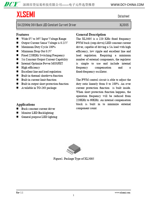
5A 220KHz 36V Buck LED Constant Current Driver XL3005FeaturesWide 8V to 36V Input Voltage Range Output Current Sense Voltage is 0.21V Maximum Duty Cycle 100% Minimum Drop Out 0.3VFixed 220KHz Switching Frequency 5A Constant Output Current Capability Internal Optimize Power MOSFET High efficiencyExcellent line and load regulation Built in thermal shutdown function Built in current limit functionBuilt in output short protection function Available in TO-263 packageApplicationsBuck constant current driver Monitor LED Backlighting General purpose LED lightingGeneral DescriptionThe XL3005 is a 220 KHz fixed frequency PWM buck (step-down) LED constant current driver, capable of driving a 5A load with high efficiency, low ripple and excellent line and load regulation. Requiring a minimum number of external components, the regulator is simple to use and include internal frequency compensation and a fixed-frequency oscillator.The PWM control circuit is able to adjust the duty ratio linearly from 0 to 100%. An over current protection function is built inside. When short protection function happens, the operation frequency will be reduced from 220KHz to 60KHz. An internal compensation block is built in to minimize external component count.Figure1. Package Type of XL30055A 220KHz 36V Buck LED Constant Current Driver XL30055A 220KHz 36V Buck LED Constant Current Driver XL3005Figure4. XL3005 Typical Application Circuit5A 220KHz 36V Buck LED Constant Current Driver XL30055A 220KHz 36V Buck LED Constant Current Driver XL30055A 220KHz 36V Buck LED Constant Current Driver XL30055A 220KHz 36V Buck LED Constant Current Driver XL30055A 220KHz 36V Buck LED Constant Current Driver XL3005 Figure13. XL3005 System Parameters Test Circuit (VIN=8V~36V, IOUT=308mA)5A 220KHz 36V Buck LED Constant Current Driver XL3005 Figure15. XL3005 System Parameters Test Circuit (VIN=8V~36V, IOUT=615mA)5A 220KHz 36V Buck LED Constant Current Driver XL3005 Figure17. XL3005 System Parameters Test Circuit (VIN=8V~36V, IOUT=925mA)5A 220KHz 36V Buck LED Constant Current Driver XL3005 Figure19. XL3005 System Parameters Test Circuit (VIN=8V~36V, IOUT=1540mA)5A 220KHz 36V Buck LED Constant Current Driver XL3005 Figure21. XL3005 System Parameters Test Circuit (VIN=8V~36V, IOUT=2140mA)5A 220KHz 36V Buck LED Constant Current Driver XL3005Figure23. XL3005 System Parameters Test Circuit (PWM DIMMING)Typical System Application (LED OVP)be limited in a suitable value by choose different zener diode when the output LED open. the zener diode Figure24. XL3005 System Parameters Test Circuit (LED OVP)5A 220KHz 36V Buck LED Constant Current Driver XL30055A 220KHz 36V Buck LED Constant Current Driver XL3005 Important NoticeXLSEMI reserve the right to make modifications, enhancements, improvements, corrections or other changes without notice at any time. XLSEMI does not assume any liability arising out of the application or use of any product described herein; neither does it convey any license under its patent rights, nor the rights of others. XLSEMI assumes no liability for applications assistance or the design of Buyers’ products. Buyers are responsible for their products and applications using XLSEMI components. To minimize the risks associated with Buyers’ products and applications, Buyers should provide adequate design and operating safeguards. XLSEMI warrants performance of its products to the specifications applicable at the time of sale, in accordance with the warranty in XLSEMI’s terms and conditions of sale of semiconductor products. Testing and other quality control techniques are used to the extent XLSEMI deems necessary to support this warranty. Except where mandated by applicable law, testing of all parameters of each component is not necessarily performed.For the latest product information, go to .。

Installation•Direct mounting(1)When joining six or more units, fix the middle part of the complete EX600 unit with anintermediate reinforcing brace (EX600-ZMB1)before mounting using 2-M4x5 screws.Tightening torque: 0.7 to 0.8 Nm.(2)Fix and tighten the end plates at one end of the unit. (M4)Tightening torque: 0.7 to 0.8 Nm.to the operation manual of the corresponding valve manifold.Fieldbus systemOperation ManualEX600-LAB1/EX600-LBB1Thank you for purchasing an SMC EX600 Series Fieldbus system.Please read this manual carefully before operating the product and make sure you understand its capabilities and limitations.Please keep this manual handy for future reference.Safety InstructionsAssemblyComposing the unit as a manifold (1)Connect the unit to the end plate.The Digital unit, Analog unit can be connected in any order.Tighten the bracket of the joint using tightening torque 1.5 to 1.6 Nm.(2)Add more units.Up to 10 units (including the SI unit) can be connected to one manifold.(3)Connecting the SI unit.After connecting the necessary units, connect the SI unit.Connecting method is the same as above (1), (2).(4)Mounting the valve plate.Apply 0.6 to 0.7 Nm tightening torque to the screws.Insert the valve plate to the valve plate set groove on the side of SI unit.Then, tighten it with the valve plate set screws (M4x6) to fix the plate.Tightening torque for set screws0.7 to 0.8 Nm.(EX600-ZMV )•DIN rail mounting(Available for series other than SY series.Refer to the catalog for SY series.)part of the complete EX600 unit with anbefore mounting, using 2-M4x6 screws.Tightening torque: 0.7 to 0.8 Nm.screws.Tightening torque: 0.7 to 0.8 Nm.(5)Fix the manifold by tightening the DIN rail fixing screws of the EX600-ZMA2. (M4x20)Tightening torque: 0.7 to 0.8 Nm.The tightening torque at the valve side depends on the valve type.valve manifold.Wiring•Connect the M12 or M8 connector cable. M12 connector is applicable for SPEEDCON connector.SPEEDCON connector wiring method is explained below.(1)Align the mark B on the metal bracket of the cable side connector (plug/socket) with the mark A.(2)Align the mark C on the unit and insert the connector into the unit vertically.If they are not aligned, the connector cannot be joined properly.(3)When the mark B of the connector has been turned 180 degrees (1/2 turn), wiring is completed. Confirm that the connection is not loose. If turned too far, it will become •Mounting the markerSignal name of the input or output devices and unit address can be written to the marker, and it can be installed to each unit.Mount the marker (EX600-ZT1) into the marker groove as required.OperatorNOTEThe direct current power supply to combine should be UL1310 Class 2 power supply when conformity to UL is necessary.Safety InstructionsMaintenance•Maintenance should be performed according to the Safety Instructions.•Perform regular maintenance and inspections.There is a risk of unexpected malfunction.•Do not use solvents such as benzene, thinner etc. to clean each unit.They could damage the surface of the body and erase the markings on the body.Use a soft cloth to remove stains.For heavy stains, use a cloth soaked with diluted neutral detergent and fully squeezed, then wipe up the stains again with a dry cloth.Refer to the SMC website (URL https://) to obtain more detailed information about maintenance.The status display LED displays the power supply and communication status.TroubleshootingRefer to the LED Display. Refer to the SMC website (URL https:// )to obtain more detailed information about troubleshooting.SpecificationRefer to the product catalog or SMC website (URL https:// ) to obtain more detailed information about product specifications.Outline with DimensionsRefer to the product catalog or SMC website (URL https://) to obtain more detailed information about outline dimensions.Note: Specifications are subject to change without prior notice and any obligation on the part of the manufacturer.© 2019 SMC Corporation All Rights Reserved Akihabara UDX 15F, 4-14-1, Sotokanda, Chiyoda-ku, Tokyo 101-0021, JAPAN Phone: +81 3-5207-8249 Fax: +81 3-5298-5362URL https://Refer to the SMC website (URL https://) to obtain more detailed information about LED display.(3)Hook the DIN rail mounting groove to the DIN rail.(4)Press the manifold using its side hooked to the DIN rail as a fulcrum until the manifold is locked.These safety instructions are intended to prevent hazardous situations and/or equipment damage.These instructions indicate the level of potential hazard with the labels of"Caution", "Warning" or "Danger". They are all important notes for safety and must be followed in addition to International standards (ISO/IEC) and other safety regulations.•Connector pin assignment EX ※※-OMX0005EX600-LAB1 (Class A)EX600-LBB1 (Class B)。

说明除列明随产品配置的配件外,本手册包含的内容并不代表本公司的承诺,本公司保留对此手册更改的权利,且不另行通知。
对于任何因安装、使用不当而导致的直接、间接、有意或无意的损坏及隐患概不负责。
订购产品前,请向经销商详细了解产品性能是否符合您的需求。
本手册所涉及到的其他商标,其所有权为相应的产品厂家所拥有。
本手册内容受版权保护,版权所有。
未经许可,不得以机械的、电子的或其它任何方式进行复制。
温馨提示1、产品使用前,务必请仔细阅读产品说明书。
2、对未准备安装的主板,应将其保存在防静电保护袋中。
3、在从包装袋中拿主板前,应将手先置于接地金属物体上一会儿,以释放身体及手中的静电4、在使用前,宜将主板置于稳固的平面上。
5、请保持主板的干燥,散热片的开口缝槽是用于通风,避免机箱内的部件过热。
请勿将此类开口掩盖或堵塞。
6、在将主板与电源连接前,请确认电源电压值。
7、请将电源线置于不会被践踏的地方,且不要在电源线上堆置任何物件。
8、当您需连接或拔除任何设备前,须确定所有的电源线事先已被拔掉。
9、为避免人体被电击或产品被损坏,在每次对整机、板卡进行拔插或重新配置时,须先关闭交流电源或将交流电源线从电源插座中拔掉。
10、请留意手册上提到的所有注意和警告事项。
11、为避免频繁开关机对产品造成不必要的损伤,关机后,应至少等待30秒后再开机。
12、设备在使用过程中出现异常情况,请找专业人员处理。
13、请不要将本设备置于或保存在环境温度高于70℃上,否则会对设备造成伤害。
目录1.产品简介 (1)1.1概述 (1)1.2产品特点 (2)1.3产品优势 (2)1.4技术指标 (3)2.细参数说明 (4)2.1产品图片 (4)2.2 测试套板接口图片 (5)2.3 COMe外形尺寸 (6)2.4 COMe连接器接口定义 (7)1.产品简介1.1概述随着具备高性能计算能力的智能装备在诸如:工业、农业、能源、国防、医疗、交通、民生等多个领域的推广和应用,越来越多的企业将大量资源,投入到高性能计算能力的智能装备的研发和生产中。

180KHz 60V 5A Switching Current Boost LED Constant Current Driver XL6006Rev 1.3Featuresn Wide 5V to 32V Input Voltage Range n Maximum Boost Output Up to 60V n 0.22V FB adjustable LED drive current n Directly drive 16 Series 1W/3W LED at VIN=24Vn Fixed 180KHz Switching Frequency n Max. 5A Switching Current Capability n Up to 94% efficiencyn Excellent line and load regulation n EN PIN TTL shutdown capability n Internal Optimize Power MOSFET n Built in Soft-Start Functionn Built in Frequency Compensation n Built in Thermal Shutdown Function nBuilt in Current Limit FunctionnAvailable in TO263-5L & TO220-5L packageApplicationsn LED Lightingn Boost constant current driver n TFT LED BacklightingGeneral DescriptionThe XL6006 regulator is fixed frequency PWM Boost (step-up) LED constant current driver, capable of driving Series 1W/3W/5W LED units with excellent line and load regulation. The regulator is simple to use because it includes internal frequency compensation and a fixed-frequency oscillator so that it requires a minimum number of external components to work.The XL6006 could directly drive 16 Series 1W/3W LED units at VIN=24V .The PWM control circuit is able to adjust the duty ratio linearly from 0 to 90%. An enablefunction, an over current protection function is built inside. An internal compensation block is built in to minimize external component count.Figure1. Package Type of XL6006180KHz 60V 5A Switching Current Boost LED Constant Current Driver XL6006 Pin ConfigurationsFigure2. Pin Configuration of XL6006 (Top View)Table 1 Pin DescriptionPin Number Pin Name Description1 GND Ground Pin.2 EN Enable Pin. Drive EN pin low to turn off the device, drive it high to turn it on. Floating is default high.3 SW Power Switch Output Pin (SW).4 VIN Supply V oltage Input Pin. XL6006 operates from a 5V to 32V DC voltage. Bypass Vin to GND with a suitably large capacitor to eliminate noise on the input.5 FB Feedback Pin (FB). The feedback threshold voltage is 0.22V. Rev 1.3180KHz 60V 5A Switching Current Boost LED Constant Current DriverXL6006Function BlockFigure3. Function Block Diagram of XL6006Typical Application CircuitFigure4. XL6006 Typical Application CircuitRev 1.3180KHz 60V 5A Switching Current Boost LED Constant Current Driver XL6006Ordering InformationPart Number Marking ID Lead Free Lead Free Packing Type XL6006TE1 XL6006TE1 Tube PackageTemperature RangeXL6006SE1XL6006SE1Tape & ReelXLSEMI Pb-free products, as designated with “E1” suffix in the par number, are RoHS compliant.Absolute Maximum Ratings (Note1)ParameterSymbol Value Unit Input VoltageVin -0.3 to 36 V Feedback Pin Voltage V FB -0.3 to Vin V EN Pin VoltageV EN -0.3 to Vin V Output Switch Pin Voltage V Output -0.3 to 60 V Power DissipationP D Internally limitedmW Thermal Resistance (TO220-5L/TO263-5L) (Junction to Ambient, No Heatsink, Free Air) R JA 30 ºC/W Operating Junction Temperature T J -40 to 125 ºC Storage TemperatureT STG -65 to 150 ºC Lead Temperature (Soldering, 10 sec) T LEAD 260 ºC ESD (HBM)2000VNote1: Stresses greater than those listed under Maximum Ratings may cause permanent damage to the device. This is a stress rating only and functional operation of the device at these or any other conditions above those indicated in the operation is not implied. Exposure to absolute maximum rating conditions for extended periods may affect reliability.Rev 1.3180KHz 60V 5A Switching Current Boost LED Constant Current Driver XL6006 XL6006 Electrical CharacteristicsT a = 25℃;unless otherwise specified.Symbol Parameter Test Condition Min. Typ. Max. Unit System parameters test circuit figure4VFB FeedbackV oltageVin = 5V to 12V, V out=24VIload=100mA209 220 231 mVEfficiency ŋVin=12V ,V out=51.2VIout=350mA- 92 - %Electrical Characteristics (DC Parameters)Vin = 12V, GND=0V, Vin & GND parallel connect a 100uf/50V capacitor; Iout=100mA, T a = 25℃; the others floating unless otherwise specified.Parameters Symbol Test Condition Min. Typ. Max. Unit Input operation voltage Vin 5 32 V Shutdown Supply Current I STBY V EN=0V 70 100 uAQuiescent Supply Current I q V EN =2V,V FB =Vin2.5 5 mAOscillator Frequency Fosc 144 180 216 KHz Switch Current Limit I L V FB =0 5 AOutput Power NMOS Rdson Vin=12V,I SW=5A35 40 mohmEN Pin Threshold V EN High (Regulator ON)Low (Regulator OFF)1.40.8VI H V EN =2V (ON) 3 10 uA EN Pin Input LeakageCurrent ILV EN =0V (OFF) 3 10 uA Max. Duty Cycle D MAX V FB=0V 90 %Rev 1.3180KHz 60V 5A Switching Current Boost LED Constant Current Driver XL6006Schottky Diode Selection TableCurrent SurfaceMountThrough Hole VR (The same as system maximum input voltage)20V 30V 40V 50V 60V1A √1N5817 1N5818 1N5819√ 1N5820 1N5821 1N5822√ MBR320 MBR330 MBR340 MBR350 MBR360 √ SK32 SK33 SK34SK35SK36 √ 30WQ03 30WQ04 30WQ05 √ 31DQ03 31DQ04 31DQ05 3A√SR302SR303SR304SR305SR306√ 1N5823 1N5824 1N5825 √ SR502 SR503 SR504 SR505 SR506 √ SB520 SB530 SB540SB550SB560 5A√50WQ0350WQ04 50WQ05Typical System Application for VIN=12V to driver 16 x 1W series LED unitsFigure5. XL6006 System Parameters Test Circuit (12V ~16 x 1W LED)Rev 1.3180KHz 60V 5A Switching Current Boost LED Constant Current Driver XL6006 Typical System Application for VIN=12V to driver 8 x 3W series LED unitsFigure6. XL6006 System Parameters Test Circuit (12V ~ 8 x 3W LED) Typical System Application for VIN=24V to driver 16 x 3W series LED unitsFigure7. XL6006 System Parameters Test Circuit (24V ~ 16 x 3W LED)Rev 1.3180KHz 60V 5A Switching Current Boost LED Constant Current Driver XL6006Typical System Application for VIN=12V to driver 16 series x 40 parallelWhite LED ArrayFigure8. XL6006 System Parameters Test Circuit (12V ~ 16 x 40 White LED) Typical System Application for SEPIC Buck-Boost LED DriverOutput Drive series 8 1W/3W LEDFigure9. XL6006 System Parameters Test Circuit (Buck-Boost LED Driver) Rev 1.3180KHz 60V 5A Switching Current Boost LED Constant Current Driver XL6006Typical System Application for VIN=12V to driver 16 x 1W series LED units With Dimming FunctionFigure10. XL6006 System Test Circuit (12V ~16 x 1W LED with Dimming Function)Rev 1.3180KHz 60V 5A Switching Current Boost LED Constant Current Driver XL6006Package InformationTO220-5LRev 1.3Datasheet 180KHz 60V 5A Switching Current Boost LED Constant Current DriverXL6006Package InformationTO263-5LRev 1.3深圳市流明圳市流明芯半导体芯半导体芯半导体照明科照明科照明科技有限公技有限公技有限公司司 深圳市民深圳市民治街道梅治街道梅治街道梅龙路彩悦龙路彩悦龙路彩悦大厦大厦406B(深圳深圳北站旁北站旁) 电话电话::************* 61348285 61348286 61348236 61348302 传真传真::************* E-mail:******************** 11。

EPM6-1V1 Watt isolated DC-DC converterProduct features• 1 Watt isolated DC-DC converter • Input voltage: 5 Vdc, 12 Vdc, and 24 Vdc • Efficiency up to 84%• Isolation voltage: 1 kVdc and 2 kVdc • SIP4 package•Operating ambient temperature from -40 °C to +90 °C• No minimum load required •IEC62368-1/ EN55032&35 certifiedEPM 6 05 1V 3R3 303 S HEaton converter Package type/size code Ordering part numberOutput current (maximum, in mA)Version codeOutput voltage (maximum, R=decimal point)Applications• Computing/telecom• Distributed power architectures • Servers and workstations • LAN / WAN applications • Data processing applications • Industrial IoT equipment, sensors • Power supply, battery backup• Wireless TX/RX modules • Renewable energy productsEnvironmental complianceS = single output, D = dual output R= Standard isolation voltage, H= High isolation voltageMaximum rated input voltage2Technical Data ELX1162Effective March 2022EPM6-1V 1 Watt isolated DC-DC converter/electronicsSpecificationsParameterConditionsMinimumTypicalMaximumUnitInputInput filter Internal capacitors1. The ripple & noise are measured with 0.1 μF capacitor at 20 MHz BW.2. All specifications valid at nominal input, full load and +25 ˚C after warm-up time unless otherwise stated.3. The product information and specifications are subject to change without prior notice.3Technical Data ELX1162Effective March 2022EPM6-1V1 Watt isolated DC-DC converter /electronics Derating curvePart numberInput voltage (Vdc)Output voltage (Vdc)Output current @ full load (mA)Efficiency 1 minimum Efficiency 1 typicalCapacitive load 2maximum (μF)EPM6051V-3R3-303S*5 3.330371%74%1500EPM6051V-05R-200S*5520075%78%1500EPM6051V-12R-084S*5128475%78%470EPM6051V-15R-067S*5156780%83%220EPM6121V-3R3-303S*12 3.330376%79%1500EPM6121V-05R-200S*12520079%82%1500EPM6121V-12R-084S*12128477%80%470EPM6121V-15R-067S*12156778%81%220EPM6241V-3R3-303S*24 3.330375%78%1500EPM6241V-05R-200S*24520076%79%1500EPM6241V-12R-084S*24128477%80%470EPM6241V-15R-067S*24156781%84%2201. Efficiency is nominal input voltage and full load @ +25 °C.2. Capacitive load is tested at minimum input voltage and a constant resistive load.3. All specifications valid at nominal input voltage, full load and +25 °C after warm-up time unless otherwise stated.4. *= Isolation option, R is for standard isolation voltage, H is for higher isolation voltage.Selection guideMeasure method4Technical Data ELX1162Effective March 2022EPM6-1V 1 Watt isolated DC-DC converter/electronicsDimensions - inches Projection: Third angle projection Unit: inchPIN tolerance: ± 0.004Tolerance: X.XX ± 0.02 X.XXX ± 0.01MarkingEMC filtering circuitClass 5 Vin 12 Vin 24 VinClass A 47 µH/ 2.2 µF 22 µH/ 2.2 µF 22 µH/ 2.2 µF Class B47 µH/ 10 µF22 µH/ 4.7 µF47 µH/ 4.7 µFPin Single1-Vin 2+Vin 3-Vout 4+VoutRecommended PCB layoutWL Y = lot code5Technical Data ELX1162Effective March 2022EPM6-1V1 Watt isolated DC-DC converter /electronicsPackaging- InchesUnit: inch1 tube = 41 pieces Length: 20.47 ± 0.08Carton = 21.46*5.71*3.94 inch41 (pieces/tube)*12(tube/bundle)*3(bundle) = 1476 piecesEatonElectronics Division 1000 Eaton Boulevard Cleveland, OH 44122United States/electronics© 2022 EatonAll Rights Reserved Printed in USAPublication No. ELX1162 BU-ELX22021March 2022EPM6-1V 1 Watt isolated DC-DC converterTechnical Data ELX1162Effective March 2022Life Support Policy: Eaton does not authorize the use of any of its products for use in life support devices or systems without the express writtenapproval of an officer of the Company. Life support systems are devices which support or sustain life, and whose failure to perform, when properly used in accordance with instructions for use provided in the labeling, can be reasonably expected to result in significant injury to the user.Eaton reserves the right, without notice, to change design or construction of any products and to discontinue or limit distribution of any products. Eaton also reserves the right to change or update, without notice, any technical information contained in this bulletin.Eaton is a registered trademark.All other trademarks are property of their respective owners.Follow us on social media to get thelatest product and support information.General informationStorage and handlingThe shelf life will be a minimum of 36 months, when stored at the following conditions: < +40 °C, < 90% RH.Wave solder profileThe wave solder profile is measured based on lead temperature. The recommended PCB pre-heat temperature is +80 °C to +100 °C, and the preheat rate of 1.5 to 2.5 °C/sec. The underside PCB temperature at the last pre-heat zone should be approximately +150 °C. The internal temperature of the solder parts should not exceed +210 °C. The duration of solder dwell time should be between 3 to 5 seconds, and not to exceed 10 seconds at a temperture of +260 °C maximum.。
180KHz 60V 5A Switching Current Boost LED Constant Current Driver XL6006FeaturesWide 5V to 32V Input Voltage Range Maximum Boost Output Up to 60V 0.22V FB adjustable LED drive current Directly drive 16 Series 1W/3W LED at VIN=24VFixed 180KHz Switching Frequency Max. 5A Switching Current Capability Up to 94% efficiencyExcellent line and load regulation EN PIN TTL shutdown capability Internal Optimize Power MOSFET Built in Soft-Start FunctionBuilt in Frequency Compensation Built in Thermal Shutdown FunctionBuilt in Current Limit FunctionAvailable in TO263-5L packageApplicationsLED LightingBoost constant current driver TFT LED BacklightingGeneral DescriptionThe XL6006 regulator is fixed frequency PWM Boost (step-up) LED constant current driver, capable of driving Series 1W/3W/5W LED units with excellent line and load regulation. The regulator is simple to use because it includes internal frequency compensation and a fixed-frequency oscillator so that it requires a minimum number of external components to work.The XL6006 could directly drive 16 Series 1W/3W LED units at VIN=24V .The PWM control circuit is able to adjust the duty ratio linearly from 0 to 90%. An enable function, an over current protection function is built inside. An internal compensation block is built in to minimize external component count.Figure1. Package Type of XL6006180KHz 60V 5A Switching Current Boost LED Constant Current Driver XL6006180KHz 60V 5A Switching Current Boost LED Constant Current Driver XL6006180KHz 60V 5A Switching Current Boost LED Constant Current Driver XL6006180KHz 60V 5A Switching Current Boost LED Constant Current Driver XL6006180KHz 60V 5A Switching Current Boost LED Constant Current Driver XL6006Figure5. XL6006 System Parameters Test Circuit (12V ~16 x 1W LED) Typical System Application for VIN=12V to driver 8 x 3W series LED unitsFigure6. XL6006 System Parameters Test Circuit (12V ~ 8 x 3W LED)180KHz 60V 5A Switching Current Boost LED Constant Current Driver XL6006Figure7. XL6006 System Parameters Test Circuit (24V ~ 16 x 3W LED) Typical System Application for VIN>=12V to driver 16 series x 40 parallelFigure8. XL6006 System Parameters Test Circuit (VIN>=12V ~ 16 x 40 White LED)180KHz 60V 5A Switching Current Boost LED Constant Current Driver XL6006180KHz 60V 5A Switching Current Boost LED Constant Current Driver XL6006 Figure11. XL6006 System Test Circuit (LED OVP)180KHz 60V 5A Switching Current Boost LED Constant Current Driver XL6006Datasheet180KHz 60V 5A Switching Current Boost LED Constant Current Driver XL6006Rev 1.6 11 Important NoticeXLSEMI reserve the right to make modifications, enhancements, improvements, corrections or other changes without notice at any time. XLSEMI does not assume any liability arising out of the application or use of any product described herein; neither does it convey any license under its patent rights, nor the rights of others. XLSEMI assumes no liability for applications assistance or the design of Buyers’ products. Buyers are responsible for their products and applications using XLSEMI components. To minimize the risks associated with Buyers’ products and applications, Buyers should provide adequate design and operating safeguards. XLSEMI warrants performance of its products to the specifications applicable at the time of sale, in accordance with the warranty in XLSEMI’s terms and conditions of sale of semiconductor products. Testing and other quality control techniques are used to the extent XLSEMI deems necessary to support this warranty. Except where mandated by applicable law, testing of all parameters of each component is not necessarily performed.For the latest product information, go to .。
青岛伊莱克斯投币洗衣机-技术参数♦技术要求型号:XQB58-161额定洗涤、脱水容量:5.8kg额定电源:220V〜50HZ额定输入功率:330W进水水压:0.03MPa〜0.6MPa外形尺寸:570×570×950(mm)♦执彳亍标准:GB/T4288-2003、GB4706.1-1998GB4706.24-2000、GB4706.26-2000GB4343.1-2003>GB17625.1-2003GB19606-2004♦颜色:◊外形颜色:瓷白◊门盖颜色:蓝色透明。
♦主要功能◊不锈钢内桶;◊静音设计;◊故障自诊断;◊运动浸泡;◊防鼠设计;◊自动断电;◊增强全塑箱体;◊超宽瀑布;◊适用毛毯、床单的强水流;◊适用轻柔衣物的弱水流;◊空气阻尼减振系统;◊数码显示。
♦产品认证C认证证书编号:3085注:以上参数若有不同以实物为准。
智能洗衣,感受科技魅力善解人意,生活变得如此简单1.双向手搓:筒与双向旋转,真正的手搓不流,深层洗涤,洗衣更干净。
2,健康杀菌:杀菌率达到99%,给家人以最好的关爱,健康杀菌,我的放心选择。
3,零水压启动:即便是超低水压的状态下,洗衣机也能正常使用。
4,智能烘干:即便阴雨天气,也没衣服晾不干的烦恼,烘干衣物,轻松制定。
5,喷淋雾态洗:洗涤水穿透衣物,洁净更节能,护衣更省心衣物更洁净,焕然衣新。
6,加热暖水洗:暖水立体护洗,洗衣加倍省心,同时确保均衡洗涤,洁净更全面O加热暖水洗真正人性科技、暖水立体护洗,26・40度黄金水温,洗净效果提升50%细致烘干,呵护恰到好处,再也不用怕阴雨天气智能烘干一体化即使阴雨天气,也没衣服晾不干的烦恼独有的热烘干技术,空气被加热,形成强劲的热气流,高温气流穿透衣物分解气味粒子并杀灭深藏于衣物的有害生物,同时使衣物内隐藏的水分蒸发成水蒸汽,以达到烘干衣物的效果。
最新推出独家钛镜面板设计时尚潮流我也赶上了豪华钛镜让生活更炫彩整体印花钢化玻璃面板设计,大圆弧造型浑然一体,引领洗衣机产品发展潮流。
MFE600系列智能电磁流量计概述MFE600系列智能电磁流量计是我公司采用国内外最先进的技术研制、开发的全智能型流量计,具有测量精度高、可靠性高、稳定性好、使用寿命长等特点。
在设计产品结构、选材、制造工艺、生产装配和出厂测试等过程中,注重每一个环节。
我们拥有高达35m的水塔作为流量实流标定的稳压装置,以及专业的电磁流量计生产设备线,设计和开发了电磁流量计专用的规模化生产软件和硬件,切实保证产品长期的高质量,高品质。
产品设计了背光宽温的中英文液晶显示屏、功能齐全实用,显示直观、操作使用方便,可以减少现场安装使用维护的麻烦。
广泛的应用于石油、化工、冶金、给排水、钢铁、煤炭、造纸、食品、轻纺、环保等工业部门及市政管理,水利建设等领域。
工作原理电磁流量计传感器根据法拉第电磁感应原理工作,在测量管轴线和磁场磁力线相互垂直的管壁上安装一对检测电极,当导电液体沿测量管轴线运动时,导电液体作切割磁力线运动产生感应电势,此感应电势由测量管上两个检测电极检出,数值大小如下式所示:E=K×B×V×D式中:E:感应电势K:仪表常数B:磁感应强度V:测量管截面内的平均流速D:测量管的内直径由电磁流量计工作原理可知,为了获得较高的测量精度,必须满足以下条件:1、被测液体必须有导电性;2、液体必须充满管道;3、液体成分必须均匀;4、如果液体导磁,流量计磁场将改变,必须对流量计进行修正。
测量流量时,流体流过垂直于流动方向的磁场,导电液体的流动感应出一个与平均流速成正比的电势,因此要求被测的流动液体高于最低限度的电导率。
其感应电压信号通过两个电极检出。
并通过电缆传送至转换器,经过信号处理及相关运算后,将累积流量和瞬时流量显示在转换器的显示屏上。
仪表特点1、电磁流量计是一种测量体积流量的仪表,流量的测量不受流体的密度、粘度、温度、压力和电导率变化的影响传感器感应电压信号与平均流速呈线性关系,测量精度高。