Aeroelastic instability of long-span suspended bridges:a multi-mode approach
- 格式:pdf
- 大小:203.37 KB
- 文档页数:9
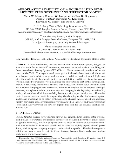
AEROELASTIC STABILITY OF A FOUR-BLADED SEMI-ARTICULATED SOFT-INPLANE TILTROTOR MODEL Mark W.Nixon1,Chester ngston2,Je rey D.Singleton3,David J.Piatak4,Raymond G.Kvaternik5,Lawrence M.Corso6,and Ross K.Brown71,2,3U.S.Army Vehicle Technology Directorate,ARLMS340,NASA Langley Research Center,Hampton,VA23681USA mark.w.nixon@,ngston@,je rey.d.singleton@4,5Aeroelasticity Branch,NASA LangleyMS340,NASA Langley Research Center,Hampton,V A23681,USAdavid.j.piatak@,raymond.g.kvaternik@6,7Bell Helicopter Textron,Inc.PO Box482,Fort Worth,TX76101,USAlcorso@,rbrown2@Key words:Tiltrotor,Soft-Inplane,Aeroelasticity,Structural Dynamics,IF ASD2003. Abstract.A new four-bladed,semi-articulated,soft-inplane rotor system,designed as a candidate for future heavy-lift rotorcraft,was tested at model scale on the Wing and Rotor Aeroelastic Testing System(WRATS),a1/5-size aeroelastic wind-tunnel model based on the V-22.The experimental investigation included a hover test with the model in helicopter mode subject to ground resonance conditions,and a forwardflight test with the model in airplane mode subject to whirl-flutter conditions.An active control system designed to augment system damping was also tested as part of this investigation. Results of this study indicate that the new four-bladed,soft-inplane rotor system in hover has adequate damping characteristics and is stable throughout its rotor-speed envelope. However,in airplane mode it produces very low damping in the key wing beam-bending mode,and has a low whirl-flutter stability boundary with respect to airspeed.The active control system was successful in augmenting the damping of the fundamental system modes,and was found to be robust with respect to changes in rotor speed and airspeed. Finally,conversion-mode dynamic loads were measured on the rotor and these were found to be significantly lower for the new soft-inplane hub than for the previous baseline sti -inplane hub.4INTRODUCTIONCurrent tiltrotor designs for production aircraft use gimballed sti -inplane rotor systems. Sti -inplane rotor systems are desirable for tiltrotors because in hover there is no concern for ground resonance,and in high-speed airplane mode the stability boundaries associ-ated with whirl-flutter have been established at velocities slightly beyond aircraft power limits,with adequate damping margins at subcritical airspeeds.The disadvantage of a sti -inplane rotor system is that significant inplane dynamic blade loads may develop, particularly during maneuvers.Presented at the2003International Forum on Aeroelasticity and Structural Dynamics,June4-6, 2003,Amsterdam,The Netherlands.This paper is declared a work of the ernment and is not subject to copyright protection in the United States.Soft-inplane rotor systems can greatly reduce the inplane blade loads in tiltrotor aircraft, thereby reducing strength requirements for the hub,leading to reduced structural weight and improved aircraft agility.It is for similar reasons that conventional helicopters with three or more blades have soft-inplane rotor systems.However,soft-inplane rotor systems generally have reduced damping margins and lower stability boundaries than sti -inplane rotor systems.Therefore,before soft-inplane rotor systems can be applied to tiltrotor aircraft,design concepts must be developed which can ensure adequate stability characteristics in both hover and forwardflight.One of thefirst soft-inplane tiltrotor designs to be proposed was the Boeing Model222. Aeromechanical behavior of this soft-inplane hingeless rotor system was addressed in sev-eral experimental and analytical studies using di erent size rotor test apparatus,beginning with a1/10-scale wind-tunnel model described in Ref.1,and ending with a full-scale26-ft.diameter semispan model tested in the NASA Ames40-x80-ft.tunnel described in Refs.2and3.The Boeing soft-inplane design had a relatively high inplane natural fre-quency(about0.9/rev at low airspeeds),such that the design rotor speed in hover mode did not create a ground resonance condition.The only experimental results associated with an instability of this configuration were obtained with the system in airplane mode subject to air resonance conditions.In general,this configuration(in airplane mode) exhibited unacceptably low damping in the wing beam mode at all airspeeds.In2001, a gimballed-hub,soft-inplane rotor system was tested on the WRATS model in hover as described in Ref.4.This rotor system had a fundamental lag frequency of0.5/rev,and hover testing showed that aeromechanical instabilities could occur at rotor speeds well be-low the design rotor speed.As this system exhibited inadequate stability characteristics in hover,it was not tested in airplane mode.More recently,a new full-scale,semi-articulated,soft-inplane rotor was designed by Bell Helicopter as part of the Army Variable Geometry Advanced Rotor Technology(VGART) program.The goals of the Bell VGART study were to satisfy Army Technical E ort Objectives for reduced weight,increased maneuverability,and reduced vibratory loads; and as part of the design to satisfy scalability issues and include growth potential to allow for more than three blades.The new soft-inplane rotor does not have a gimbal, but instead uses a standardflaphinge for the blades.It also adds a highly-damp ed elastomeric-bearing in the blade lag direction(the term semi-articulated is used because the lag mechanism with elastomeric-bearing has both hinge andflexural qualities).The inplane(lag)frequency of the rotor was designed to be in a range of0.55/rev to0.75/rev to maximize the dynamic loads reduction capabilities of the soft-inplane system while retaining feasibility for full-scale application.The new soft-inplane rotor also has four blades,rather than three as used on the previous sti -inplane ing the results from this VGART study,a new1/5-size,four-bladed,soft-inplane hub was designed and fabricated for the WRATS tiltrotor model.The new four-bladed,semi-articulated,soft-inplane rotor system was tested on the Wing and Rotor Aeroelastic Testing System(WRATS),a1/5-size aeroelastic tiltrotor wind-tunnel model based on the V-22.The experimental investigation included a hover test with the model in helicopter mode subject to ground resonance conditions,and a forward flight test with the model in airplane mode subject to whirl-flutter conditions.The ob-jectives of the investigation were to determine the damping margins,stability boundaries, and load reduction factors associated with the new soft-inplane rotor as compared to the current baseline sti -inplane rotor system.Also included as part of this investiga-tion was testing of an active control system designed to augment system damping.Thethree-bladed sti -inplane rotor system(used in several past investigations documented inRefs.5-8)was examined under the same conditions as the four-bladed soft-inplane hub toprovide a baseline for comparison.2APPARATUSThe WRATS1/5-size semi-span tiltrotor model was used as the test-bed for these exper-iments,and the important characteristics of this wind-tunnel model have been describedin several previous reports such as Ref.9,Ref.10,and most recently Ref.5.The wind-tunnel test was performed at the Langley Transonic Dynamics Tunnel(TDT),and thehover test was performed in a30x30-ft.hover cell located in an adjacent high-bay build-ing.While the TDT can use R-134a refrigerant as a test medium,the current experimentwas conducted using air at atmospheric pressures.The key geometric features of the new soft-inplane hub and the baseline sti -inplane hubare illustrated in Fig.1,and several important attributes of these rotor systems are listedin Table1.Some significant features of the soft-inplane hub are a0.5inch pre-lead usedto reduce the steady lag response associated with blade drag,aflap hinge o set of1.76inches(e q=0.039),and a lag pivot point of5.76inches(e l=0.126).The outer pitch bearing is coincident with the lag pivot.As shown,the pitch links have been movedfrom a trailing-blade position on the three-bladed sti -inplane hub to a leading-bladeposition on the four-bladed soft-inplane hub.Both hubs have a nominal geometric B3(pitch-flap skew angle)of about15 ,but for the soft-inplane systemflap-up movementproduces pitch-down rotation while for the sti -inplane hubflap-up movement producespitch-up rotation.The pitch-flap and pitch-lag couplings for the soft-inplane hub weremeasured as a function of blade collective pitch position(collective measured at the75%span station),and are plotted as the e ective geometric B3and B4angles,respectively,inFig.2.The pitch-flap coupling is shown to change rapidly at low collectives where it hasa higher than nominal value,but in the normal collective range associated with airplanemode(20 to50 )the pitch-flap coupling remains in a±1 band about the nominal15value.The pitch-lag coupling is shown to be about9 over the20 to50 collectiverange with about the same deviation band of±1 ,and lag(aft)movement produces apitch-down rotation.The four-bladed,soft-inplane rotor system had two sets of elastomeric dampers thatwere used in the tests so that the e ects of lag mode frequency placement could beexamined(the dampers provide both damping and sti ness to the lag hinge).The softerset of dampers produced a nominal lag mode frequency of0.57/rev while the sti er set ofdampers produced a nominal lag mode of0.63/rev(based on an888RPM design rotorspeed in hover).Only the soft damper set was used in the hover test,while both setswere used in the wind-tunnel test.3HOVER TESTINGThe four-bladed,soft-inplane rotor system was tested in both isolated-rotor and coupled-system configurations.For the isolated-rotor case the pylon was clamped to the rotortest stand such that thefixed-system frequencies were well above the rotor frequenciesof interest,and for coupled-system testing the wing was cantilevered to the test standwith fundamental elastic wing bending modes free to interact with the rotor system.Frequencies of the three key coupled-system modes are plotted as a function of rotorspeed in Fig.3.The three modes are the rotor lag mode(with the0.57/rev damper set installed),the wing beam mode,and the wing torsion/chord(WTC)mode.Coupling between the rotor lag and WTC modes increases as the lag mode frequency(nonrotating frame)approaches the WTC frequency at the upper rotor speed range(lag perturbation stick-stirs produce significant WTC response).Without su!cient damping,this condition will generally result in a ground resonance type instability.The coupled-system damping associated with these three modes is shown in Figs.4,5,and6,where it is seen that there is no instability associated with any of the modes over the rotor speed range tested.A likely reason for these results is the high value of lag mode damping provided by the elastomeric damper as indicated in Fig.4.For the isolated rotor the nominal value for damping is about12%with little variation over rotor speed,while the coupled system the damping is generally higher and varies from12%to18%over the rotor speed range shown.The measured frequency of the rotor lag mode was approximately the same for the isolated and coupled configurations.An important result from the hover testing was that both the measured frequency and measured damping of the rotor lag mode are in close proximity to those expected for full-scale applications of soft-inplane tiltrotor systems.It should be noted when viewingfigures that most plots presented in this paper show error bars.This indicates that a minimum of5data points are available for the indicated condition,with the data point representing the average of the available records and the error bar indicating the standard deviation from the average.In some cases there were less data acquired,and for these cases the individual data records are shown(Figs.5and 6for example).On most plots,faired lines(either linear or cubic spline)are used to help indicate the data trends.The frequency of the WTC mode,which is the key wing mode associated with inplane hub motion and ground resonance behavior in hover,is about5.6Hz and remains steady with respect to rotor speed as shown in Fig.3.Damping of this crucial mode is shown in Fig.5for two collective pitch settings,0 and10 as measured at the75%radial station. As shown,the damping begins at about2%critical in the lower rotor speed range,then falls to a minimum of about1%at800RPM.The soft-inplane system did not encounter an instability under normal operating conditions.In previous studies with a soft-inplane gimballed rotor system(Ref.4)the WTC mode was found to become unstable.Thus,it appears that the new semi-articulated hub design,with use of highly-damped elastomeric materials,provides adequate damping to avoid aeromechanical instability over the design rotor speed range.The wing beam mode in hover is not highly coupled with the rotor lag mode(lag pertur-bation stick-stirs produce little wing beam response),and previous studies indicate that this mode is not likely to become unstable.However,as this is the lowestfixed-system mode(5.4Hz natural frequency)it was monitored carefully throughout the hover test. Fig.6shows the damping associated with the wing beam mode as a function of rotor speed,and indeed this mode is more highly damped than the WTC mode(for l>300 RPM).The damping does,however,decrease with rotor speed from about5%critical at the peak to about2%critical at the upper end of the rotor speed spectrum.Figs.5and6also show that,for the semi-articulated,soft-inplane rotor,the collective pitch setting has little e ect on the WTC and wing beam mode dampings.This is contrary to the behavior observed for the gimballed,soft-inplane rotor system investigated in Ref.4 where the blade pitch setting was found to have a significant impact on damping.Theexact cause of the damping change with collective that was observed in Ref.4has yet to be determined,but may be associated with the particular design and not a general characteristic of gimballed soft-inplane rotor systems.4WIND-TUNNEL TESTINGThe new four-bladed,soft-inplane rotor system,oriented in airplane mode for high-speed wind-tunnel testing,is shown in Fig.7mounted on the WRATS testbed in the NASA Langley Transonic Dynamics Tunnel(TDT).The basic dynamics of the wing/pylon/rotor system shifts substantially with conversion to airplane mode,as the mass o set of the py-lon/rotor moves from above to forward of the elastic axis,and thus creates a significant coupling between the wing beam and torsion modes and the rotor lag mode.The wing chord mode becomes predominantly isolated from these modes in the airplane configura-tion.For airplane-mode aeroelastic stability testing,the rotor system is normally operated windmilling(unpowered and disconnected from the drive system),with the collective blade pitch used to adjust the rotor speed,and a near-zero torque at the rotor shaft.This represents the most conservative manner to test the stability of the system(no damping from the drive system).Under windmilling operation,damping of the key mode associated with system stability(the wing beam mode)was determined to be significantly less for the new four-bladed soft-inplane hub than for the three-bladed sti -inplane(baseline)system, as shown in Fig.8.Damping of the wing beam mode was generally less than1.0%in windmillingflight for all the soft-inplane configurations considered(on-downstop(D/S), o -D/S;0.57/rev dampers,0.63/rev dampers;550,742,and888RPM rotor speeds). Unfortunately,these damping characteristics are inadequate for full-scale operation.In powered-mode(200in-lb torque maintained)the system damping and the stability boundary both increased significantly as illustrated in Fig.9(note on-D/S configuration shown rather than o -D/S as used in Fig.8because of low damping associated with the o -D/S case).Although not a solution for the low-damping behavior associated with the windmilling condition,these results represent a substantial deviation from previous results associated with the baseline system,wherein the e ect of power is not significant with respect to the stability boundary.Fig.10shows that while the subcritical damping values increase significantly with power for the sti -inplane rotor system,the instability condition is about the same.5STABILITY AUGMENTATION TESTINGThe active control system examined in this study incorporates wing-root bending mea-surements(strain gages)for feedback and applies control signals to three independent swashplate hydraulic actuators.The active control algorithm was developed cooper-atively between Bell and NASA Langley,and is based on the Generalized Predictive Control(GPC)theory presented in Refs.11and12.Past studies that have successfully demonstrated the stability augmentation capability of the GPC theory for tiltrotors are documented in Refs.13and14.The GPC active stability augmentation system was highly successful in application to both the new soft-inplane and the baseline sti -inplane rotor systems in high-speedflight. Fig.11shows very significant increases in damping associated with closed-loop control of the baseline system that are extended well beyond the open-loop stability boundary.For the open-loop system the instability occurs at a velocity of about105kts.Closed-looptesting proceeded to a velocity of150kts.before testing was terminated,which is45 kts.beyond the open-loop stability boundary(100kts beyond for full-scale).In fact,the damping of the wing beam mode is shown to be increasing as a function of the airspeed, rather than decreasing,as is the custom for the open-loop system.Similar results were also obtained for the new soft-inplane rotor system as shown in Fig.12,although the system was not tested as far beyond the stability boundary as the baseline system. While not shown on a plot,damping of the wing chord and torsion modes also increased substantially under GPC,otherwise the system would eventually become unstable in these modes.Data were also acquired within the same run at several rotor speeds between550 and888RPM,and the GPC control system was not adversely a ected by these changes in rotor speed.Data from this test show that it is possible to attain the damping levels required for acceptable operation of a soft-inplane rotor system using GPC,and the control system shows robustness with respect to both rotor speed and airspeed deviations.6CONVERSION LOAD MEASUREMENTSThe last objective of this test was to demonstrate the reduction in hub and blade dy-namic loads,which is the key benefit of using soft-inplane rotor systems.Blade and hub loads were measured for a defined set of pylon conversion angles(0,15,30,45,60, 75,and90degrees)and cyclic pitch settings(flapping up to3degrees)in combination, which are designed to simulate tiltrotor free-flight maneuvers.The dynamic loads at each instrumented blade station were measured for each of variousflight conditions,and the maximum sustained dynamic loads(half-peak-to-peak of all conditions considered to-gether)are plotted in Fig.13as a function of span.As expected,the soft-inplane rotor system produces significantly lower dynamic loads.A reduction of approximately50%in the highest(midspan)loads is indicated on the plot.7CONCLUSIONSAn experimental study of a new four-bladed,semi-articulated,soft-inplane hub designed for the WRATS tiltrotor testbed was conducted in hover and forwardflight.Based on results of the tests,the following conclusions are indicated:1.The lag-mode frequency and damping of the new soft-inplane rotor system were measured and found to be representative what can be obtained at full-scale.2.In hover,the new soft-inplane rotor system produced adequate levels of damping throughout the rotor speed spectrum.Ground resonance does not appear be a problem for the current soft-inplane design.3.In windmilling airplane mode,damping levels for the new soft-inplane rotor system were extremely low and insu!cient for full-scale application.4.For the soft-inplane rotor,there is a large increase in system damping associated with moving from the windmilling to the powered-mode operating condition.For the baseline sti -inplane design,subcritical damping increases,but there is not a significant change in the stability boundary.5.The GPC-based active stability augmentation system was very e ective at increas-ing damping in all the fundamental wing modes simultaneously,for both the soft-inplane and sti -inplane rotor systems.6.The GPC controller was very robust with respect to rotor speed and airspeed, with the system damping for the sti -inplane rotor still increasing at45knots beyond the corresponding open-loop instability condition.7.A substantial reduction of blade and hub dynamic loads was obtained for the new soft-inplane design as compared to the baseline sti -inplane design during conversion mode operations.8REFERENCES1.Alexander,H.R.,Hengen,L.H.,and Weiberg,J.A.:“Aeroelastic-Stability Char-acteristics of a V/STOL Tilt-Rotor Aircraft with Hingeless Blades:Correlation of Analysis and Test.”American Helicopter Society30th Annual National Forum, Washington D.C.,May,1974.2.Magee,J.P.,Alexander,H.R.,Gillmore,K.B.,Richardson,D.A.,and Peck,W.B.:“Wind Tunnel Tests of a Full Scale Hingeless Prop/Rotor Design for the Boeing Model222Tiltrotor Aircraft.”Report No.D222-10059-1,Contract NAS2-6505, April,1973.3.Johnson,W.:“Dynamics of Tilting Proprotor Aircraft in Cruise Flight.”NASATN D-7677,May,1974.4.Nixon,M.W.,Langston,C.W.,Singleton,J.D.,Piatak,D.J.,Kvaternik,R.G.,Corso,L.M.,and Brown,R.K.:“Hover Test of a Soft-Inplane Gimballed Tiltro-tor Model.”Journal of the American Helicopter Society,Vol.48,No.1,January, 2003.5.Piatak,D.J.,Kvaternik,R.G.,Nixon,M.W.,Langston,C.W.,Singleton,J.D.,Ben-nett,R.L.,and Brown,R.K.:“A Parametric Investigation of Whirl-Flutter Stability on the WRATS Tiltrotor Model.”Journal of the American Helicopter Society, Vol.47,No.3,July,2002.6.Nixon,M.W.,Piatak,D.J.,Corso,L.M.,and Popelka,D.A.:“Aeroelastic Tailoringfor Stability Augmentation and Performance Enhancements of Tiltrotor Aircraft.”Journal of the American Helicopter Society,Vol.45,No.4,October,2000.7.Corso,L.M.,Popelka,D.A.,and Nixon,M.W.:“Design,Analysis,and Test of aComposite Tailored Tiltrotor Wing.”Journal of the American Helicopter Society, Vol.45,No.3,July,2000.8.Nixon,M.W.,Kvaternik,R.G.,and Settle,T.B.:“Tiltrotor Vibration ReductionThrough Higher Harmonic Control.”Journal of the American Helicopter Society, Vol.43,No.3,July,1998.9.Settle,T.B.,and Kidd,D.L.:“Evolution and Test History of the V-220.2ScaleAeroelastic Model.”Journal of the American Helicopter Society,Vol.37,No.1, January,1992.10.Settle,T.B.and Nixon,M.W.:“MA VSS Control of an Active Flaperon for TiltrotorVibration Reduction.”American Helicopter Society53rd Annual Forum Proceed-ings,pp.1177—1193,Virginia Beach,Virginia,April29-May1,1997.11.Clarke,D.W.,Mohtadi,C.,and Tu s,P.S.:“Generalized Predictive Control—Parts I and II.”Automatica,Vol.23,No.2,1987,pp.137-160.12.Juang,J.-N.and Phan,M.Q.:Identification and Control of Mechanical Systems.Cambridge Univ.Press,New York,NY,2001.13.Kvaternik,R.G.,Juang,J.,and Bennett,R.L.:“Exploratory Studies in Gen-eralized Predictive Control for Active Aeroelastic Control of Tiltrotor Aircraft.”Presented at the American Helicopter Society Northeast Region Specialists’Meet-ing on Active Controls Technology,Bridgeport,CT,October4-5,2000(Paper is also available as NASA/TM-2000-210552).14.Kvaternik,R.G.,Piatak,D.J.,Nixon,M.W.,Langston,C.W.,Singleton,J.D.,Ben-nett,R.L.,and Brown,R.K.:“An Experimental Evaluation of Generalized Predic-tive Control for Tiltrotor Aeroelastic Stability Augmentation in Airplane Mode of Flight.”Journal of the American Helicopter Society,Vol.47,No.3,July,2002.Table1:Key rotor system properties.Twist147.5 47.5Rotor Weight214.59lb16.94lbHub Weight37.189lb9.703lbBlade Weight4 2.167lb 1.770lbBlade FlapInertia0.2330slug-ft20.1265slug-ft2Hover RPM888888Cruise RPM742742Airfoil start8.0in7.5inLift curve slope(nom.) 5.9/rad 5.9/radTipchord 4.470in 3.250inRoot chord 6.510in 4.190in0.75R chord 5.069in 3.757inSolidity,j50.1060.105Precone 2.50 2.75 6Geometric B3-15.0 +15.0Geometric B4—+9.012Includes all blades,hub,pitch links,and hub attachment to mast hardware.3Includes hub,nose cone,pitch links,bearings,and blade cu s.4Per blade,from hub attachment point outboard,includes ballast weight inserts.5Based on chord at75%radius.6This number has little meaning for the current study because there was noflaphinge spring.Fig. 1. Schematics of the two hub types tested.05101520KinematicCoupling,deg.Rotor Lag Damping (Rotating System),% Crit.Rotor Speed, RPM Rotor Speed, RPM Fig. 4. Rotor lag mode damping as a function of rotorspeed (0.57/rev damper set).Fig. 5. Wing torsion/chord mode (WTC) dampingas a function of rotor speed (0.57/rev damper set).(a) The 4-bladed semi-articulated soft-inplane hub. (b) The 3-bladed gimballed stiff-inplane hub.Wing BeamDamping,% Crit.Rotor Speed, RPM7654321Fig. 6. Wing beam mode damping as a function of rotor speed (0.57/rev damper set).Fig. 7. The four-bladed soft-inplane rotor mountedon the WRATS testbed for airplane mode testingin the TDT.-0.50.51.01.52.02.5Velocity, kts.Wing Beam Damping,% crit.-101234Velocity, ktsWing BeamDamping, % crit.Fig. 8. Comparison of wing beam mode dampingbetween the soft-inplane (0.63/rev damper set) andthe stiff-inplane rotor system (742 RPM, off-D/S,windmilling).Fig. 9. Comparison of wing beam mode damping between the windmilling and powered conditions for the soft-inplane rotor system (0.63/rev damper set, 742 RPM, on-D/S).Blade Station, in.HPTPBending Moment, in-lb.02001601208040on wing beam mode damping for the soft-inplane rotor system (742 RPM, on-D/S, wind-milling,0.63/rev damper set)Fig. 13. Effect of hub type on blade dynamic loads (half-peak).1234567Wing Beam Damping,% crit.Velocity, kts1020Velocity, kts.Wing Beam Damping,% crit.Fig. 10. Comparison of wing beam mode damping between the windmilling and powered conditions for the stiff-inplane rotor system (742RPM, off-D/S).Fig. 11. Effect of GPC active stability augmentation on wing beam mode damping for the stiff-inplane rotor system (742 RPM, off-D/S).11。
Journal of Wind Engineeringand Industrial Aerodynamics90(2002)2023–2032Full aeroelastic model test of a super long-span bridge with slotted box girder Hiroshi Sato a,*,Nobuyuki Hirahara a,Koichiro Fumoto a,Shigeru Hirano b,Shigeki Kusuhara ba Structures Research Group,Independent Administrative Institution Public Works Research Institute,1-6Minamihara,Tsukuba-shi,Ibaraki-ken305-8516,Japanb Engineering Management Division,Long-span Bridge Engineering Center,Honshu-Shikoku Bridge Authority,Urban Ace Sannomiya Bldg.4-1-22Onoe-dori,Chuo-ku,Kobe-shi,Hyogo-ken651-0088,JapanAbstractAerodynamic stability is one of the most important themes in the design of super long-span bridges.In order to improve aerodynamic stability,various researches were conducted and it was confirmed that slotted box girder with some devices shows good aerodynamic stability(J. Wind Eng.Ind.Aerodyn.88(2000)297).In this paper,the results of full aeroelastic model test andflutter analysis(two-and three-dimensional)for a generic super long-span bridge,whose main span is2.8km,are described.It was confirmed that slotted box girder was applicable for the super long-span bridge for the reason that it is excellent in economical efficiency and aerodynamic stability.r2002Elsevier Science Ltd.All rights reserved.Keywords:Aerodynamic stability;Super long-span bridge;Flutter analysis;Full aeroelastic model; Slotted box girder1.IntroductionThere are several plans or ideas of strait crossing road projects in Japan(Fig.1).In these projects,super long-span bridges longer than the Akashi Kaikyo Bridge may be included.In the design of such super long-span bridges,aerodynamic stability is one of the most important themes.Furthermore,reduction of construction cost is also required.Therefore,Independent Administrative Institution Public Works Research Institute(IAIPWRI)and Honshu-Shikoku Bridge Authority(HSBA)have *Corresponding author.0167-6105/02/$-see front matter r2002Elsevier Science Ltd.All rights reserved.PII:S0167-6105(02)00318-5been conducting a cooperative study on the super structure of super long-span bridges that have good aerodynamic stability and economical efficiency.In previous studies [1]by the authors,it was found that a slotted box girder with some devices has good aerodynamic characteristics.Therefore,the slotted box girder was applied to a generic super long-span bridge,and full aeroelastic model test was conducted.The result was compared with three-dimensional flutter analysis.2.Basic flutter characteristics of slotted box girderWe proposed a stiffening girder whose cross section is shown in Fig.2.This box girder has 4lanes,where 2lanes are on the grating installed on the slot in consideration of economical efficiency.We measured 3-component forces and unsteady aerodynamic forces using the section model of this box girder whose scale was 185:Coefficients of 3-compornent forces are shown in Fig.3.In super long-span bridges,torsional rigidity may decrease and torsional deformation may become large.Therefore,unsteady aerodynamic forces were measured for angles of attack from 01to À121.The defined coordinate system is shown in Fig.4.Coefficients of the unsteady aerodynamic forces were defined as follows:L ¼pr f B 2½L zR o 2z þL zI o z 0 þB 3½L y R o 2yþL y I oy 0 þB 2½L yR o 2y þL yI o y 0 g ;ð1ÞFig.1.Strait crossing road projects in Japan.H.Sato et al./J.Wind Eng.Ind.Aerodyn.90(2002)2023–20322024M ¼pr f B 3½M zR o 2z þM zI o z 0 þB 4½M y R o 2y þM y I oy 0þB 3½M yR o 2y þM yI o y 0 g ;ð2ÞD ¼Àpr d f B ½D zR o 2z þD zI o z 0 þB 2½D y R o 2y þD y I oy 0þB ½D yR o 2y þD yI o y 0 g ;ð3ÞFig.2.Cross section of slotted boxgirder.Fig.3.Coefficients of 3-component forces.H.Sato et al./J.Wind Eng.Ind.Aerodyn.90(2002)2023–20322025where,L is the lift,M the aerodynamic moment,D the drag,z the vertical displacement,y the torsional displacement,y the horizontal displacement,B the girder width,d the girder depth,o the circular frequency,()0:d()/d t ;L xx ;M xx or D xx the coefficients of unsteady aerodynamic forces (Subscript z means coefficient caused by vertical vibration;y caused by torsional vibration;y caused by horizontal vibration;R in phase with displacement;I the in phase withvelocity).Fig.4.Definition of forces anddisplacement.Fig.5.Measured coefficients of unsteady aerodynamic forces.H.Sato et al./J.Wind Eng.Ind.Aerodyn.90(2002)2023–20322026The measured coefficients are shown in Fig.5.These figures show that unsteady aerodynamic forces are influenced by angle of attack.Especially,M y I ;which influences flutter characteristic greatly,became positive when the angle of attack was À71to À91.Then,two-dimensional flutter analysis was performed with a measured coefficient of unsteady aerodynamic forces.Analysis conditions are shown in Table 1.The result of analysis is shown in Fig.6.This figure shows that the flutter characteristic was getting worse when the angle of attack was about À71where M y I became positive.The triangle mark of Fig.6is a result of a spring-supported test.Analytical values agreed fairly well with the experimental value.Therefore,it was decided that the measured coefficient was applicable for flutter analysis.3.Wind tunnel study with a full aeroelastic model3.1.Full aeroelastic modelA suspension bridge,whose main span length is 2800m and total length is 5000m (Fig.7),was assumed as a prototype bridge of this study.Table 1Analysis conditionMass of dead loadm 0.215kg/m Polar moment of inertiaI P0.00246kg m 2/m Girder size Width B0.276m Depth D0.032m FrequencyVertical f Z0.674Hz Torsional f y1.312Hz Ratio f y =f Z1.96Fig.6.Effect of attack angles on flutter speed of section model.H.Sato et al./J.Wind Eng.Ind.Aerodyn.90(2002)2023–20322027HSBA has a large boundary wind tunnel facility in Tsukuba.It was built in 1991as one of the cooperative efforts between PWRI and HSBA in order to verify the aerodynamic stability of a super long-span bridge such as the Akashi Kaikyo Bridge,and to establish the wind resistant design method for super long-span bridges considering three-dimensional effects of structure and flow.The test section of this wind tunnel is 41m wide,4m high and 30m long,and maximum wind speed is 12m/s.It is one of the largest boundary layer wind tunnels in the world.Therefore,the scale ratio of a full aeroelastic model of an assumed super long-spanbridge was 1:Structural dimensions of the bridge and the model are shown in Table 2.3.2.Wind tunnel test results for the full aeroelastic modelStatic deformation by wind load is shown in Fig.8and Photo rge horizontal deformation (leeward side)and large torsional deformation (head down)were measured at the center of mainspan.Fig.7.Assumed super long-span bridge.Table 2Structure dimensions of super long-span bridgeAssumed bridge Model value(b)/(a)Required (a)Measured (b)Scale—1/1251/125—MassM 28.41t/m 1.818kg/m 2.100kg/m 1.156Polar moment of inertiaI P 388t m 2/m 0.00159kg m 2/m 0.00246kg m 2/m 1.547Girder size WidthB 34.5m 0.276m 0.276m 1.000DepthD 4.0m 0.032m 0.032m 1.000Stiffness Vertical EI V1.707kNm 2/box 9.384Nm 2/box 12.277Nm 2/box 1.308Horizontal EI H3.107kNm 2/box 48.828Nm 2/box 12.277Nm 2/box 0.251Torsional GJ1.090kNm 2/box 6.906Nm 2/box 6.853Nm 2/box 0.992Natural frequencyVertical 1st0.0621Hz 0.693Hz 0.674Hz 0.9732nd0.0990Hz 1.111Hz 1.106Hz 0.995[1st]0.0610Hz 0.683Hz 0.703Hz 1.029[2nd]0.0831Hz 1.499Hz 1.494Hz 0.997Torsional 1st0.1256Hz 1.369Hz 1.321Hz 0.965[1st]0.1466Hz 1.600Hz 1.597Hz 0.998Horizontal 1st0.0316Hz 0.352Hz 0.352Hz 1.000[1st]0.0550Hz 0.502Hz 0.491Hz 0.978[]means asymmetrical mode.H.Sato et al./J.Wind Eng.Ind.Aerodyn.90(2002)2023–20322028Logarithmic decrement at each wind speed is shown in Fig.9.It increased gradually with wind speed,and then began decreasing at a wind speed of about 6m/s.After that,logarithmic decrement decreased,changed to negative value at 8.8m/s,and flutter started.According to the similarity law of Froude’s number,flutter speed for the assumed bridge would be about 100m/s ðD 8:8m =s Âffiffiffiffiffiffiffiffi125p Þ:Fig.8.Deformation ofgirder.Photo 1.Static deformation of super long-span bridge (wind speed=8m/s).H.Sato et al./J.Wind Eng.Ind.Aerodyn.90(2002)2023–203220294.Flutter analysis for the full aeroelastic modelThree-dimensional flutter analysis for the full aeroelastic model was conducted by using the measured unsteady aerodynamic forces.The analytical method was the same as the one used for the Akashi Kaikyo Bridge [2].The conditions of three-dimensional flutter analysis are shown in Table 3.In the analysis,static deformation was calculated first,then unsteady aerodynamic forces corresponding toattackFig.9.Apparent damping—wind velocity.Table 3The conditions of flutter analysisItemAnalysis condition Analytical methodMode combination ing lower 50modes.Air density0.12kg/m 3Structural dampingAll modes:d ¼0:02Coefficients of aerodynamic forces Main girderForceVertical Torsional Horizontal LiftJ J *MomentJ J *Drag J J *J ;Unsteady aerodynamic forces*;Quasi-steady aerodynamic forcesCable:Quasi-steady drag and lift force (C D ¼0:7)Tower:Not consideredH.Sato et al./J.Wind Eng.Ind.Aerodyn.90(2002)2023–20322030angle of the girder were introduced.After that,eigenvalues were calculated using 50vibrational modes in still air.Modified torsional stiffness was used for the calculation so that torsional natural frequency might become equal to the measured value.The analytical results of static deformation are shown in Fig.10.As for horizontal displacement and vertical displacement,the analytical values agreed well with experimental values.However,the analytical value for the torsional deformation was slightly smaller than the experimental value.Therefore,the flutter analysis was carried out using the measured torsional deformation.The change of apparent damping of the 1st torsional symmetrical mode (mode 19)is shown in Fig.11by the triangle mark.The flutter speed from the three-dimensional flutter analysis was 7.9m/s.It agreed fairly well with theexperiment.Fig.10.Results of static deformation.H.Sato et al./J.Wind Eng.Ind.Aerodyn.90(2002)2023–20322031Since the mass and polar moment of inertia of the model were larger than the values required from the similarity laws,flutter analysis was conducted for the required values of the model.The flutter speed was 7.6m/s.Therefore,flutter speed for the assumed bridge would be estimated about 85m/s,which confirmed its aeroelastic stability.5.ConclusionsFull aeroelastic model test and three-dimensional flutter analysis was conducted for a generic super long-span bridge.The results and conclusions obtained are summarized as follows:(1)The slotted box girder was applied to a generic super long-span bridge,whosemain span length was assumed to be 2.8km.Wind tunnel study was conductedwith a 1125full aeroelastic model in smooth flow.It was confirmed that its flutterspeed was high enough.(2)Three-dimensional flutter analysis was conducted for the full aeroelastic model.In the analysis,unsteady aerodynamic forces corresponding to attack angles of the girder deformed by steady wind forces were introduced.The calculated flutter speed agreed fairly well with the experiment.References[1]H.Sato,S.Kusuhara,et al.,Aerodynamic characteristics of super long-span bridges with slotted boxgirder,J.Wind Eng.Ind.Aerodyn.88(2–3)(2000)297–306.[2]T.Miyata,H.Sato,et al.,Full model wind tunnel study on the Akashi Kaikyo Bridge,Proceedings ofthe Ninth International Conference on Wind Engineering,1995,pp.793–798.Fig.11.Apparent damping—wind velocity (1st torsion symmetrical mode).H.Sato et al./J.Wind Eng.Ind.Aerodyn.90(2002)2023–20322032。

中石油托福考试听力partB真题中石油托福考试听力题型均为传统老托福样式,听力前20道题目均为短对话形式。
第二部分是15道短对话,男女3句对话方式。
第三部分是3长对话和1篇lecture,也是15道。
下面就是我给大家带来的托福考试听力真题,希望能关怀到大家!听力part B原题31.(A) There aren’t enough cabinets.(B) There is too much noise.(C) Office supplies are taking up space.(D) Some teaching assistants don’t have desks.32.(A) To chat with Jack socially.(B) To get help in the course.(C) To hand in their assignments.(D) To practice giving interviews.33.(A) Give Jack a different office.(B) Complain to the department head.(C) Move the supplies to the storage room.(D) Try to get a room to use for meetings. 34.(A) They’d have to get permission.(B) Jack wouldn’t like it.(C) She thinks it might work.(D) The other assistants should be consulted.35.(A) Mating habits of squid and octopus.(B) The evolution of certain forms of sea life.(C) The study of marine shells.(D) Survival skills of sea creatures.36.(A) He didn’t understand the lecture.(B) He wants to borrow her notes next week.(C) He needs help with a makeup exam.(D) He was sick and unable to attend.37.(A) Some sea creatures developed vertebrae.(B) The first giant squid was captured.(C) Some sea creatures shed their shells.(D) Sea life become more intelligent.38.(A) She has always believed they exist.(B) She heard about them in New Zealand.(C) Stories about them may be based on giant squid.(D) The instructor mentioned them in the lecture.参考答案:B B DC BD C C听力原文:Questions 31-34A: Stan, do you have a minute?B: Oh, hi, Cathy, sure. What’s up?A: Well, I’ve been meaning to talk to you about the situation in the office.B: I’m not in there very often. It’s so noisy that I can’t work.A: That’s exactly what I’m getting at. We’re supposed to be able to do our preparationand marking in that office. But have you notice? Jack constantly has students comingin to get help with his course. A lot of people are going in and out.B: Has anybody spoken to him about it?A: No, not yet. But someone’s going to have to.B: We can’t really ask him to stop having students come in for help, can we?A: No, of course not. But I’m not able to do my work and neither are you. I imagine it’s the same for the others in the office.B: Hum… could we ask for a kind of meeting room? When TAs have to talk with thestudents, they could go to the meeting room and not use the office. You know, there’s a room down the hall, a rather small room that we could ask to use. It’s only for storing supplies.A: You mean that little storage room? Oh, that would be too small.B: Are you sure? With the cabinets taken out, it might be bigger than it looks.A: Come to think of it, you maybe on to something. I’d like to have a look at that room.B: Can we go there now?A: Sure, let’s go.31. What problem at the office are Cathy and Stan discussing?32. Why do Jack’s students come to see him?33. What does Stan suggest they do?34. What does Cathy say about Stan’s suggestion?Questions 35-38A: I really appreciate you’re filling me in on yesterday’s lecture.B: No problem. I thought you might want to go over it together. And anyway, it helpsme review. Hope you’re feeling better now.A: I am, thanks. So you said she talked about squid? Sounds a little strange.B: Well, actually, it was about the evolution of sea life, a continuation from last week.A: The octopus and the squid descended from earlier creatures with shells. They survivedby shattering(打碎)their shells, somewhere between 200 and 500 million years ago.B: That’s a pretty long span of time.A: I know. That’s what she said though. To be precise, exactly when theyemerged isuncertain and why is still unexplained.中石油托福考试听力partB真题B: Some squid are really huge. Can you imagine something that big if it still hadashell?A: Actually, it’s because they lost their shells that they could evolve to a biggersize.B: Make sense. But some are really huge. I’ve read about fishermen that caughtsquid that weight over a ton. Did she talk about how that happens?A: Not really, but she did mention some unusual cases. In 1933 in New Zealand,theycaught a squid… let’s see here… it was 22 yards long. Its eyes were 18 inchesacross.B: Can you imagine?A: Reminds me about all those stories of sea monsters.B: Doctor Simpson thinks there are probably even larger ones that haven’t beenfound,because squid are intelligent and fast—so they can easily get away fromhumans.A: Maybe some of those monster stories are true.35. What topic are the man and woman discussing?36. Why does the man need to talk to the woman about the class?37. According to the woman, what happened 200 to 500 million years ago?38. What does the woman imply about sea monsters?。

摘要多丽丝·莱辛(1919-)被认为是当代英国最重要的作家之一,也被誉为是继伍尔夫(Woolf)之后,英国最伟大地女性作家之一。
她不仅长寿,而且创作生命也很旺盛。
她一生不断地转变写作类型,但始终没变的是那一代人对于社会持之以恒的关注。
英国文学传统,特别是19世纪现实主义传统及创作手法,是她一生的创作基调。
《野草在歌唱》就是她早期创作的一部反映现实主义题材的小说。
《野草在歌唱》讲述的是女主人公玛丽在西方殖民主义与男权中心的双重枷锁下,找不到自己合适的位置。
家庭里受丈夫主宰,社会中受白人排挤,因而内心世界逐渐失衡直至精神错乱的悲剧故事。
小说还描写了黑人摩西对自我身份的追寻,虽然最后以失败告终,但其表现出来的颠覆潜能,预言了殖民统治的瓦解。
另外,小说对白人社团内部殖民者对穷苦白人的剥削和压迫的刻画,也反映了殖民统治行将末日的先兆。
整部小说传达了作者对殖民统治下白人女性生存困境的深切关注,对受压迫的非洲人民的同情和对殖民统治的强烈谴责。
本论文认为,《野草在歌唱》中所有的人物都是悲剧性人物。
为了更准确深入地揭示人物的命运和产生的社会根源,论文针对小说中的三种人物类型—女性,黑人和殖民者—分别采取了女性主义批评,后殖民主义批评和新历史主义等文学批评方法。
经过论证,论文发现以下结果:一、以玛丽为代表的女性,在男权统治的社会里,无法按自己的意愿选择自己的生活,婚前不能选择独身,婚后又失去了工作的权利,只能从属于丈夫或男性。
玛丽最后被摩西杀死的悲剧是整个社会对女性摧残的结果,而不仅仅是摩西的过错;二、以摩西为代表的黑人,在白人殖民的土地上,他们失去了主人的地位,只能为白人充当廉价的劳动力,受尽他们的剥削和歧视。
摩西身上寄托了作者莱辛对黑人的期许,他身上有普通黑人身上没有的善良、温情、教养和尊严。
用《摩西十诫》中的“摩西”作为小说中黑人代表的名字,传达了莱辛对黑人种族的同情,也肯定了黑人对白人殖民反抗力量的正义性;三、同样身为白人,莱辛对白人殖民者作了无情的揭示和鞭挞。

飞行器稳定性与操纵性(英)_西北工业大学中国大学mooc课后章节答案期末考试题库2023年1.是飞机横向静稳定性的最大来源。
答案:机翼2.短周期自然频率主要取决于以下哪个参数?答案:3.对于无上反的后掠机翼来说,侧滑角会改变哪些参数?答案:弦向速度_局部动压_展向速度4.为降低操纵力,调整片应与操纵面同向偏转。
答案:错误5.右侧扰流板打开时,飞机会向右滚。
答案:正确6.升力系数越高,后掠角对横向静稳定性的贡献越小。
答案:7.同样的飞机,重心适当后移可使飞机的配平性能提高。
答案:8.对于后掠机翼,左侧滑情况下,右侧机翼动压大于左侧机翼动压。
答案:9.侧洗会垂尾前缘处的侧滑角。
Sidewash will the sideslip angle of the verticaltail leading edge.答案:增大increase10.按照本课程的符号定义习惯(国际坐标系),绕x轴向右滚转为,绕z轴向左偏航为。
According to the sign convention in this course (international coordinate system), roll to the right about the x-axis is , and yaw to the left about the z-axis is .答案:正,负positive, negative11.惯性轴系与地轴系之间相差了一个。
The difference between the Inertialsystem and Earth-fixed system is .答案:地球自转earth rotation12.方向舵偏为正,会产生偏航力矩 Rudder deflect to the is positive, and ayawing moment will be generated.答案:左,左left, left13.以下哪些角度是基础体轴系与风轴系间的夹角?Which of the followingangles are the angles between the basic body Axes System and the Wind Axes System?答案:迎角Angle of attack_侧滑角Sideslip angle14.舰载机在起飞离舰瞬间,升力会突然增加。
Editorial/AnnouncementCompetent 足以胜任的;有能力的;称职的;合格的Rotary 旋转的;绕轴转动的bio-inspired design 仿生设计aeroelasticity 空气弹性变性acoustics 声学;(房间、戏院的)传声效果expertise 专长;专门知识;专门技能fidelity 忠诚忠实尽责保真度multidisciplinary (涉及)多门学科的maneuverability n.可操作性;驾驶性能optimization 最佳的最优的最优化aeroelastic空气弹性变型的configurations 配置;结构;外形;布置demanding 要求高的;需要高技能(或耐性等)的;费力的;要求极严的constant 连续发生的;不断的;重复的;不变的Administrator (公司、机构的)管理人员In addition I want to express special thanks to the editors-in-chief of all other AIAA technical journals for constant communication and frequent help and advice.Thorough adj.彻底的;完全的;深入的;细致的thoroughness n.透彻完全Prompt 准时的及时的迅速的提示Reviews 评论;回顾;审查;检查Manuscripts 抄本原稿Potential 潜在的可能的Innovation 创新;改革;(新事物、思想或方法的)创造;新思想Evaluation 评价Dedicated 专注的;专用的Gratitude 感激之情;感谢Aeronautics 航空(学)的Astronautics 宇航The American Institute of Aeronautics and Astronautics (AIAA)Editor-in-Chief 主编总编辑Submit 提交呈送使服从使顺从derive from 起源于来自scope (题目、组织、活动等的)范围;能力perception 感知;知觉;看法;洞察力conviction 说服定罪确信信念observance 遵守(法律,规则,传统等);(宗教的,正式的)仪式observed 观察;注意;看到;说vital 必不可少的;对…极重要的;生命的;维持生命所必需的violations 侵犯;违背;妨害;【体】违例Obligations义务;责任;债务;负担Authority 权威;权力;当局;授权Delegate n.代表;会议代表v.授(权);把(工作、权力等)委托(给下级);选派(某人做某事)Confer 协商;商讨;交换意见;授予(奖项、学位、荣誉或权利)Unbiased 公正的;不偏不倚的;无偏见的Impartial 公正的;不偏不倚的;中立的Merits n.优点价值功过功绩v.值得。
类型长/m宽/m高/m 混凝土强度等级钢绞线规格屋面板墙板23.49/23.92/26.4913.95/18.302.982.981.00.7C45C45Øs 15.2×7Øs 15.2×70前言随着国家和地方政府大力推广预制装配式建筑的政策落实,越来越多建筑工程项目采用预制装配式结构,但目前来看,混凝土预制结构在住宅项目中应用较为广泛,从设计到生产和施工管理均有较成熟的经验,而在商业办公及公共建筑项目中,因跨度较大,且建筑形态多样,在应用上有一定的难度,尤其在中心城区的商办项目,采用预制混凝土结构的项目较少[1-2]。
大跨度预应力混凝土双T 板(以下简称双T 板)是商业、办公等公共建筑中常用的预制混凝土结构构件,具有跨度大、结构性能好、整体性好、成本低等特点[3]。
本文基于工程实际,介绍先张法生产大跨度双T 板的生产工艺,主要包括生产过程中钢绞线张拉与放张、混凝土浇筑、构件养护等关键操作要点,并对预应力控制、预拱度控制、裂纹控制提出了针对性方法,以期为大跨度双T 板的批量生产和推广应用提供参考。
1工程概况某工业厂房长189.6m ,宽124.3m ,采用单层排架结构,结构高度17.05m ,占地面积23500m 2。
厂房屋面及围护墙均采用大跨度双T 板,屋面板及墙板用双T 板规格见表1。
双T 板为梁板结合的构件,其屋面板所受荷载主要包括恒载(结构自重、防水材料自重、预埋件自重)+活载(积灰)。
在结构设计时,纵肋下部配置预应力筋。
通过施加预应力的方式抵抗使用阶段产生的拉力。
同时,偏心预压力产生预拱度。
屋面板及墙板配筋见图1。
经有限元分析可知,屋面板在正常使用阶段,由钢绞线承受绝大部分拉力。
2大跨度双T 板生产工艺大跨度双T 板构件采用先张法生产工艺,其主要生产流程见图2。
2.1清理模具首先,对双T 板模具的板面、纵肋和横肋进行清扫,以清理底面和侧面混凝土碎渣和积水。
大跨度桥梁静风失稳分析摘要大跨度桥梁具有轻柔、纤细的特点,其静风稳定性问题突出。
本文利用风荷载增量与两重迭代相结合的方法, 运用有限元分析论对空气静力行为和失稳过程进行分析,探讨大跨度桥梁静风失稳临界状态判据以及失稳形态。
关键词:大跨度桥梁;静风失稳;非线性;临界状态The analysis of long-span bridges’ calm wind instability YANG HU Southwest Jiaotong University 611756 Abstract:Large-span bridges have the characteristics of soft and thin, which calm wind stability problem is prominent.In this paper, using the method of combining wind load increment and twofold iterative analyzed aerostatic behavior and the process of instability with the help of the theory of finite element analysis. Besides, we discussed long-spanb ridges’ critical state criterion of wind instability and forms of instability. Key words:large span bridges; calm wind instability; nonlinear; critical state0.前言随着桥梁跨度的不断增大,桥梁结构在风荷载作用下的静力风稳定性问题日益突出。
根据试验发现,大跨度桥梁发生静风失稳的临界风速可能低于动力失稳的临界风速。
非线性能量阱在大跨度桥梁涡致振动控制中的应用作者:***来源:《西部交通科技》2023年第11期摘要:文章对非线性能量阱在大跨度桥梁涡致振动控制中的应用进行研究,将桥梁涡振激励等效为简谐荷载,建立涡激力下桥梁结构-NES动力学模型,基于数值搜索方法,给出NES 参数设置及优化策略,并以国内某大跨度钢箱梁悬索桥为例,对NES的涡振控制性能进行数值模拟分析。
结果表明,NES能有效抑制桥梁结构涡振响应幅值,其较无控制时降低了约84%。
研究结果可为相关工程建设提供一定的理论和实践指导,对于解决桥梁涡致振动问题具有重要意义。
关键词:非线性能量阱;大跨度桥梁;涡激共振;结构振动控制;非线性振动0引言近年来,随着现代交通事业的飞速发展,特大型桥梁建设的规模和数量也在不断扩大。
大跨度的桥梁在为人们出行带来了更多便利的同时,也使桥梁结构在风荷载作用下所产生的动力响应越发明显,涡激振动便是大跨度桥梁常遇见的问题之一。
桥梁涡振是一种限幅振动,尽管其很少造成桥梁结构性破坏,但会影响行车体验感、舒适性,易诱发交通安全事故。
因此,如何采取有效的措施减缓或消除桥梁涡致振动现象日益成为研究者们关注的焦点[1]。
调谐质量阻尼器(Tuned Mass Damper,TMD)是一种被动控制技术,因其具备安全可靠、经济实用、易于施工等特点,在桥梁工程风振控制中得到广泛应用。
例如,日本东京湾航道桥、中国崇启长江公路大桥和西堠门大桥等都使用了TMD技术对桥梁涡振进行控制,工程实践结果表明其能有效地降低桥梁结构的风振响应,提高桥梁的安全性能[2-3]。
然而TMD 技术也存在许多问题,如对主体结构动力特性变化敏感、作用频段单一等,这极大地阻碍了TMD的发展。
近年来,随着非线性动力学理论的不断丰富与发展,具有非线性特性的质量阻尼器——非线性能量阱(Nonlinear Energy Sink,NES)已成为一种新型的振动控制手段,其相较于传统TMD装置,具有更宽的减振频带及更强的鲁棒性,在许多领域得到了广泛研究[4-6]。
Journal of Wind Engineeringand Industrial Aerodynamics74—76(1998)849—857Aeroelastic instability of long-span suspended bridges:a multi-mode approachPiero D’Asdia ,Vincenzo Sepe *Dipartimento di Ingegneria Ci v ile,Uni v ersita%di Trieste,P.le Europa,1-34127Trieste,ItalyDipartimento di Ingegneria Strutturale e Geotecnica,Uni v ersita%di Roma**La Sapienza++,Via Eudossiana,18-00184Rome,ItalyAbstractFor long-span suspended bridges,the aeroelastic stability analysis performed by means of a rigid section model can be sometimes inadequate,while a multi-mode approach gives better results with only a slightly larger computational burden.In this paper the current design of the proposed bridge on the Messina Strait(main span3300m)has been examined taking into account vertical,lateral and torsional modes,both around the dead loads equilibrium config-uration and around the average configuration in windflow.The investigation shows an excellent aeroelastic behaviour of such bridge,confirming the design results. 1998Elsevier Science Ltd.All rights reserved.Keywords:Suspended bridge;Aeroelastic stability;Flutter;Messina Bridge1.IntroductionAeroelastic instability of long-span bridges is usually tackled by means of(i)wind tunnel tests on rigid section or full bridge aeroelastic models;(ii)non-linear analyses in the time domain with appropriate wind time histories;(iii)stability analysis of a2d.o.f.rigid section model through linearized equations of motion.In the latter case, the frequencies usually corresponds to thefirst vertical and torsional natural modes. When the stiffness of the superstructure is mainly due to the cables(veryflexible decks)it can be shown[1]that some pairs of vertical and torsional natural modes (and not just thefirst one)are similar in shape to each other and exhibit similar ratios between the two frequencies.When the stability analysis is performed assuming rigid*Corresponding author.E-mail:sepe@scilla.ing.uniroma1.it.Structural Consultant for the design of the Bridge on the Messina Strait.0167-6105/98/$19.00 1998Elsevier Science Ltd.All rights reserved.PII:S0167-6105(98)00077-4section model,all these pairs of modes nearly give the same values of the critical reduced frequency and of the ratios between the critical angular frequency and the natural ones(although,different critical velocity).Also,this type of analysis cannot take into account the components of displacement along wind,nor the possibility of a synchronisation to the same frequency of more than two modes(in or out of phase). Retaining the concept of wind-induced oscillations near an equilibrium configura-tion through linearized equations,a multi-mode approach can often improve the analysis with only a slightly larger computational burden.This approach is quite usual in aeronautical engineering,and its application to civil engineering has already been suggested for long-span bridges[2,3].In the approach described here the natural modes are obtained by a FEM analysis taking into account geometrical non-lineari-ties and stiffness,and the critical wind speed is found by means of an eigen-value—eigenvector procedure implemented ad hoc,that also gives the shape of the critical oscillating configuration(flutter mode shape).As an example,the multi-mode approach has been applied to the proposed Messina bridge.2.Multimode approachThe simplest and well-known way to tackle with the aeroelastic stability of a bridge is to consider a rigid section model,taking into account only displacements due to the first vertical and torsional modes(2d.o.f)or also to thefirst along-wind mode(3d.o.f). However,the contribution of an increasing number of natural modes is likely to become more and more important with an increasing length,and also transversal displacements are expected to play a significant role.Nevertheless,a multi-mode approach to the aeroelastic instability,described since70’s[2],has only recently been applied from a technical point of view[3—5].It consists in describing self-excited oscillations around a significant equilibrium configuration through linearized equa-tions,taking into account an adequate number of natural modes.Denoted by x the coordinate along the axis,by non-dimensional h(x,t)and p(x,t)the ratios between vertical or transversal(along-wind)displacements and the width B of the deck and by (x,t)the torsional rotation,by h H(x,t),p H(x,t), H(x,t)the corresponding displacement components of j th natural mode and by H the j th modal coordinate,it resultsh(x,t)"H H(t)h H(x),p(x,t)"HH(t)p H(x), (x,t)"HH(t) H(x).(1)Denoting also by I H, H,and H the j th mode inertia,damping and angular frequency, and taking into account thefirst N modes,the dynamics is described by the equationsI H[ $H#2 H H H# H H]"Q H) ,j"1,2N.(2) In Eq.(2)Q H are generalized aerodynamic forcing terms that—differently from structural forces on the left side—depend in general from the contributions of the whole set of natural modes;namely,the lift and drag forces and the aeroelastic moment per unit length¸ ,D ,M (Fig.1)can be expressed in the classical Scanlan 850P.D+Asdia,V.Sepe/J.Wind Eng.Ind.Aerodyn.74–76(1998)849–857Fig.1.Coordinates and aeroelastic actions on the deck.formulation [6,7]as a function of coordinates h ,p and and corresponding velocities h ,p and ,through coefficients H *H ,P *H and A *H known as flutter derivatives .H *H ,P *H and A *H can be obtained by experiments in wind tunnels and expressed as a function of the reduced frequency K "B /º,where in turn and ºdenote the angular frequency of the imposed motion and the mean wind velocity (orthogonal to the bridge axis),respectively.Denoted also by the air density and by ())the derivative with respect to the time t ,it resultsQ H ) "[¸ h H (x )B #D p H (x )B #M H(x )]d x (3)and then,once expressed ¸ ,D ,M as a function of flutter derivatives according to Ref.[7]Q H ) "12 º B P KH * (K )B ºh H h P P #KH * (K )B ºh H P P#K H * (K )h H P P d x # PKP * (K )B ºp H p P P #KP * (K )B ºp H P P #K P * (K )p H P P d x # P KA * (K )B º H h P P#KA * (K )B º H P P #K A * (K ) H P P d x .(4)Defining as critical the wind velocity corresponding to self-sustained (harmonic)oscillations,the equations governing the motion can be expressed in the frequency domain (instead of the mixed time-frequency domain of Eq.(4)),once defined"[ ,2, ,]2" e S R " e )Q , 3",, 3",, 31,s "ºt B ;(5)P.D +Asdia,V.Sepe /J.Wind Eng.Ind.Aerodyn.74–76(1998)849–857851the amplitude G is a complex number taking into account the possibility of differences of phase between the motion components.Introducing also the notation K H"B H/º, the j th equation becomes[!K #2i H K H K#K H] H"12I HB K P[i H* (K)G(h P,h H)#i H* (K)G( P,h H)#H* (K)G( P,h H)] P#P[i P* (K)G(p P,p H)#i P* (K)G( P,p H)#P* (K)G( P,p H)] P#P[i A* (K)G(h P, H)#i A* (K)G( P, H)#A* (K)G( P, H)] P .(6)In Eq.(6),G(s K,q L)denotes the scalar product between the s and q components of the m th and n th natural modes,that isG(s K,q L)" s K q L d x,s,q"h,p, ,m,n"1,2,2,N.(7)The cross products G(s K,q L)with m O n correspond to the contribution given by displacements and velocities in the n th mode to the m th generalised force,and so they take into account the modal coupling due to aerodynamic forces.A unimodal approach has sometimes been proposed[8],which neglects such coupling (G(s K,q L)K$L"0).The unimodal approach turns out to be safe for bluff-body bridge decks,because the energy transferred from thefluid comes into a single mode instead of being spread into more than one,and so the evaluated critical wind velocity is lower.However,whenever the bridge deck has been properly designed from an aerodynamic point of view so that a1d.o.f instability can be excluded,as usually done for modern bridges,such approach become unsafe,while of course the possibility remains offlutter,with2d.o.f or more.In matricial form,Eq.(6)become[C(K, )#i D(K, )] "0.(8) The existence of steady-state oscillations with amplitude is only possible if both the real and imaginary parts Re and Im of the determinant det(C#i D)vanish,that leads to equations in K and ,whose solution(if it exists)can be obtained numer-ically.Finally,the critical(orflutter)speedºA"B /K comes out.Then, denotes the angular frequency of the critical oscillating configuration(flutter mode),to which several natural modes contribute,possibly out of phase but synchronised to each other due to aerodynamic forces;the critical shape correspond to the eigenvector of the problem[C(K , )#i D(K , )] "0.(9) 852P.D+Asdia,V.Sepe/J.Wind Eng.Ind.Aerodyn.74–76(1998)849–8573.Example:the proposed bridge on the Messina StraitThe multi-mode approach described in the previous section has been applied to the current design of the proposed bridge on the Messina Strait,with main span of 3300m (Fig.2).The first 20natural modes around the dead loads equilibrium configuration or around the average configuration in wind flow have been evaluated through a FEM model (5000d.o.f.)and a computer code able to take into account geometrical non-linearities and stiffness (relevant modes in Fig.3).When appropriate,average values of mass M per unit length and torsional mass moment of inertia I per unit length have been evaluated taking into account both main cables and deck;namely,M "5.5;10 kg/m,I "2.8;10 kg m /m.Depending on the modes considered,a structural damping H varying from 0.6%to 0.9%has been assumed.From Fig.3it is observed that several pairs of vertical and torsional modes have wave lengths of many hundreds or even over one thousand meters and nearly identical mode shapes.For such pairs,the ratio between the frequencies of a torsional mode and the corresponding vertical mode is close to the ratio between the deck half-width and the polar inertia radius,indicating [1,9]that the deck stiffness is negligible compared to the cable stiffness.For all these pairs,therefore,the stability analysis performed through the rigid section model gives almost the same critical values of the reduced frequency K and of the ratio X " / between the critical frequency and the frequency of the vertical (or torsional)mode,and therefore critical wind velocities proportional to such natural frequencies [1].Using the aeroelastic derivatives in Fig.4,obtained through the experimental investigation performed during the design studies,the multi-mode approach is able to provide within the same analysis more solutions (Fig.5),according to the number of modes taken into account.The critical wind speed,corresponding to the lowest value (94m/s),is in quite a goodagreement Fig.2.Current design of the proposed bridge on the Messina Strait (measures expressed in meters).P.D +Asdia,V.Sepe /J.Wind Eng.Ind.Aerodyn.74–76(1998)849–857853Fig.3.Natural modes around the dead loads equilibriumconfiguration.Fig.4.Flutter derivatives.Data from design reports and Ref.[10](f " /2).Fig.5.Results of multi-mode analysis.Curves Re( ),I m( )for K "0.276(solution 1Nº).854P.D +Asdia,V.Sepe /J.Wind Eng.Ind.Aerodyn.74–76(1998)849–857P.D+Asdia,V.Sepe/J.Wind Eng.Ind.Aerodyn.74–76(1998)849–857855 with the analytical and experimental results obtained during design studies.The values H*G,A*H introduced in Eq.(4)and shown in Fig.4are defined according to Scanlan[7];they are related to analogous h*G,a*H,used in the representation conven-tion proposed in Ref.[10],as follows:H* "!h* /K,H* "h* /K,H* "!h* /K ,A* "a* /K,A* "!a* /K,A* "a* /K .Critical values of reduced frequency K(Fig.5)are very small and so it has been sometimes necessary to extrapolate aeroelastic derivatives in Fig.4 (K "0.2760º/(fB)"22.7).In the example shown,solutions obtained through the multi-mode approach are very close to the ones given by the rigid section model when the subsequent pairs of vertical and torsional modes are considered.However,it cannot be excluded that situations differing in the bridge geometry and/or characterised by non-uniform mean wind distributions,could amplify such differences,or even show phenomena not forecast by the rigid section model.For the current example,differences of some2m/s in the critical wind speed have also been observed when natural modes around the dead loads equilibrium configura-tion have been substituted by modes around the deformed configuration in windflow (see table in Fig.5).In any case the multi-mode approach should not be a priori excluded whenever aerodynamic coupling between modes is expected to arise due to closeness of natural frequencies,as it is likely to occur for so deformable systems;e.g.,angular frequencies of the ten modes b—m in Fig.3are within the range0.35—0.80rad/s,and in such a range several axial modes are also included.In particular,it can be observed that the second vertical mode f has nearly the same frequency of thefirst torsional one d:this introduced difficulties in their numerical evaluation but,above all,it indicates that no one of this mode can be excited independently from the other one,as confirmed by wind tunnel experiments performed on a1:250model during the design studies;in fact,such experiments showed that—both in still air or in a windflow—measured transfer functions of vertical or torsional displacements due to vertical or torsional harmonic excitation cannot be correctly identified if compared to analytical ones corresponding to a two-mode model;instead,a more satisfactory agreement is found when analytical transfer functions are obtained taking into account at least three natural modes(first vertical,first torsional,second vertical)[11,12].It is also important to evaluate the role of horizontal displacements along-wind (lateral modes),whose contribution can be stabilising or not depending on the deck geometry and on the mode shapes;here,for example,the mode b along-wind has exactly the same shape(see Fig.3)of thefirst vertical one c and also a very close frequency(and so it is expected to give aerodynamic coupling);the mode h,whose frequency is close to that of the third vertical mode i,is instead orthogonal to it.The role of lateral modes is underlined in a recently published paper[13],where it is shown that for the Akashi—Kaikyo Bridge a multi-mode analysis performed neglect-ing the drag components offlutter derivatives associated with heaving and pitching motion gives an unacceptable overestimation of theflutter wind speed(more than856P.D+Asdia,V.Sepe/J.Wind Eng.Ind.Aerodyn.74–76(1998)849–857135m/s instead of75m/s).This seems not to be the case of the proposed design of the Messina Bridge,that is characterised by a very streamlined deck and has therefore an excellent aerodynamic behaviour.In fact,a preliminary investigation[14]performed including also thefirst two lateral modes and aerodynamic coupling with torsional ones,turns outflutter wind speed close to the values in Fig.5.In such investigation, the aeroelastic derivatives P*G corresponding to along-wind modes were evaluated from the static drag coefficient C",available from wind tunnel tests,according to the pseudo-steady formulation(P* "!2C"/K,P* "(d C"/d )/K,P* "(d C"/d )/K ,see Ref.[7]).4.Further applicationsThe possibility to evaluate the sensitivity of these structures to quasi-deterministic components[15]of the wind turbulence(namely,random in time and deterministic in space)is also interesting in this approach,and it is related to the following consider-ations:(i)the wind turbulence components that are significant for ordinary structures usually fall in the high frequency range(sub-inertial and inertial range)and are described as a stochastic process in time and space domain.This is not the case of turbulence components with frequencies below0.10—0.15Hz that—for design purpose of large structures with low natural frequencies—can be satisfactory described in terms of main vortices,whose spatial distribution can approximately be modelled as quasi-deterministic;(ii)a design turbulence can therefore be defined, that is not aimed to reproduce real wind histories,but that can be used to evaluate the sensitivity of the structure to appropriate components of wind velocityfluctu-ations in significant directions only.To this end,wind histories can be generated through weighted amplitude wave superposition(WAWS)techniques adopting just the significant part of the turbulence spectrum,giving random phase distributions in a chosen point of the bridge axis,and relating the phase distributions along the span through deterministic relations,depending on the frequencies and distances.Aeroelas-tic forces so obtained can easily be taken into account in the described multi-mode approach.5.Concluding remarksThe paper describes the use of a multi-mode approach in the aeroelastic stability analysis of the proposed bridge on the Messina Strait;vertical,lateral and torsional modes are taken into account,both around the dead loads equilibrium configuration and around the average configuration in windflow.The numerical investigation, based onflutter derivatives obtained in wind tunnel tests during the design studies, confirm the excellent aeroelastic behaviour of the bridge,whose design was carefully assessed through experimental and numerical analysis on rigid section models in several scales,non-linear analyses in the time domain with appropriate wind time histories and wind tunnel tests on a1:250full-bridge aeroelastic model.P.D+Asdia,V.Sepe/J.Wind Eng.Ind.Aerodyn.74–76(1998)849–857857 AcknowledgementsThis research has been made possible by the grant MURST40%1994—1996“Vento,strutture e ambiente:progettazione,controllo e normativa”of the Italian Ministry of University and Research.Both reviewers are gratefully acknowledged for their comments and criticism,that allowed to improve readability of the paper.Mr. Luca Caracoglia is also acknowledged for his collaboration to the computer codes implementation and for some numerical results,obtained during the preparation of his Degree Thesis in Civil Engineering,University of Trieste.References[1]V.Sepe,E.Ciappi,P.D’Asdia,Instabilita aeroelastica multimodale di ponti sospesi,Proc.4th ItalianNational Conf.on Wind Engineering IN-VENTO-96,Trieste,Italy,September1996,pp.293—308(in Italian).[2]R.H.Scanlan,The action offlexible bridges under wind,I:Flutter theory,J.Sound Vibr.60(2)(1978)187—199.[3]A.Jain,N.P.Jones,R.H.Scanlan,Coupled aeroelastic and aerodynamic response analysis oflong-span bridges,J.Wind Eng.Ind.Aerodyn.60(1996)69—80.[4]A.Namini,P.Albrecht,H.Bosch,Finite element-basedflutter analysis of cable-suspended bridges,ASCE J.Struct.Mech.118(6)(1992)1509—1526.[5]H.Tanaka,N.Yamamura,M.Tatsumi,Coupled modeflutter analysis usingflutter derivatives,J.Wind Eng.Ind.Aerodyn.41/44(1992)1279—1290.[6]R.H.Scanlan,J.J.Tomko,Airfoil and bridge deckflutter derivatives,ASCE J.Eng.Mech.97(EM6)(1971)1717—1737.[7]E.Simiu,R.H.Scanlan,Wind Effects on Structures,3rd Edn.,Wiley,New York,1996.[8]R.H.Scanlan,Interpreting aeroelastic models of cable-stayed bridges,ASCE J.Eng.Mech.113(4)(1987)555—575.[9]F.C.Smith,G.S.Vincent,Aerodynamic stability of suspension bridges with special reference to theTacoma Narrows bridge,a Report of an investigation,University of Washington Engineering Experiment Station,Bulletin No.116,1950,Part II—Mathematical analyses.[10]A.Zasso,Flutter derivatives:advantages of a new representation convention,J.Wind Eng.Ind.Aerodyn.60(1996)35—47.[11]A.Zasso,S.Cigada,S.Negri,Flutter derivatives identification through full bridge aeroelastic modeltransfer function analysis,J.Wind Eng.Ind.Aerodyn.60(1996)17—33.[12]G.Diana,M.Falco,S.Bruni,A.Cigada,rose,A.Damsgaard,A.Collina,Comparisonsbetween wind tunnel tests on a full aeroelastic model of the proposed bridge over Stretto di Messina and numerical results,J.Wind Eng.Ind.Aerodyn.54/55(1995)101—113.[13]H.Katsuchi,N.P.Jones,R.H.Scanlan,H.Akiyama,Multi-modeflutter and buffeting analysis of theAkashi—Kaikyo bridge,8th U.S.Nat.Conf.on Wind Engineering,The Johns Hopkins University, Baltimore,MD,5—7June1997.[14]G.Augusti,V.Sepe,P.D’Asdia,L.Caracoglia,Wind-induced oscillations of long-span suspensionbridges,CEAS International Forum on Aeroelasticity and Structural Dynamics,Roma,17—20June 1997,AIAA-AIDAA,Vol.II,pp.183—190.[15]P.D’Asdia,A.Viskovic,Un modello di vento nel dominio del tempo,Proc.4th Italian Nat.Conf.onWind Engineering IN-VENTO-96,Trieste,Italy,September1996,pp.155—166(in Italian).。