Cisco2950交换机安装配置
- 格式:doc
- 大小:181.00 KB
- 文档页数:22

2950交换机简明配置维护手册目录第1章说明 (3)第2章产品特性 (3)第3章配置端口 (3)3.1配置一组端口 (3)3.2配置二层端口 (5)3.2.1配置端口速率及双工模式 (6)3.2.2端口描述 (7)3.3监控及维护端口 (8)3.3.1监控端口和控制器的状态 (8)3.3.2刷新、重置端口及计数器 (10)3.3.3关闭和打开端口 (10)第4章配置VLAN (11)4.1理解VLAN (11)4.2可支持的VLAN (12)4.3配置正常范围的VLAN (12)4.3.1生成、修改以太网VLAN (13)4.3.2删除VLAN (15)4.3.3将端口分配给一个VLAN (15)4.4配置VLAN Trunks (16)4.4.2使用STP实现负载均衡 (19)第5章配置Cluster (23)第1章说明本手册只包括日常使用的有关命令及特性,其它未涉及的命令及特性请参考英文的详细配置手册。
第2章产品特性2950是只支持二层的交换机支持VLAN•到250 个VLAN•支持VLAN ID从1到4094(IEEE 802.1Q 标准)•支持ISL及IEEE 802.1Q封装安全•支持IOS标准的密码保护•支持标准及扩展的访问列表来定义安全策略•支持基于VLAN的访问列表监视•交换机LED指示端口状态•SPAN及远端SPAN (RSPAN) 可以监视任何端口或VLAN的流量•内置支持四组的RMON监控功能(历史、统计、告警及事件)第3章配置端口3.1 配置一组端口当使用interface range命令时有如下的规则:•有效的组范围:o vlan从1 到4094o fastethernet槽位/{first port} - {last port}, 槽位为0o gigabitethernet槽位/{first port} - {last port},槽位为0o port-channel port-channel-number - port-channel-number, port-channel号从1到64•端口号之间需要加入空格,如:interface range fastethernet 0/1 –5是有效的,而interface range fastethernet 0/1-5是无效的.•interface range命令只能配置已经存在的interface vlan•所有在同一组的端口必须是相同类别的。

VLAN的划分与互通实验准备工作:按照下图所示,连接实验环境。
如果没有设备,可下载Boson NetSim局域网交换与路由模拟器。
拓扑图:配置过程:说明:本实验完全在Boson Netsim模拟器上完成,下面红色下划线文字均为配置过程输入的命令。
一、交换机2950B配置1、配置交换机主机名、管理ip、默认网关Switch>enSwitch#config tSwitch(config)#hostname 2950B2950B(config)#int vlan 12950B(config-if)#ip address 172.16.10.3 255.255.255.0 //设置管理IP地址2950B(config-if)#no shut2950B(config-if)#exit2950B(config)#ip default-gateway 172.16.10.1 //设置默认网关IP地址2、配置中继口(即trunk口)2950B(config)#int f0/12950B(config-if)#switchport mode trunk2950B(config-if)#exit2950B(config)#int f0/42950B(config-if)#switchport mode trunk2950B(config-if)#exit2950B(config)#int f0/52950B(config-if)#switchport mode trunk2950B(config-if)#exit2950B(config)#3、配置vtp,把2950B交换机设置成客户机模式,2950B从2950C接收vlan信息2950B#vlan database2950B(vlan)#vtp client2950B(vlan)#vtp domain cisco4、创建Vlan2950B(vlan)#vlan 2 name sales // 将vlan 2设置名称为sales2950B(vlan)#vlan 3 name marketing // 将vlan 2设置名称为marketing 2950B(vlan)#apply2950B(vlan)#exit5、将交换机端口分配到vlan中2950B#config t2950B(config)#int f0/22950B(conf-if)#switchport mode access // 设置二层交换端口2950B(config-if)#switchport access vlan 22950B(config-if)#exit2950B(config)#int f0/32950B(conf-if)#switchport mode access // 设置二层交换端口2950B(config-if)#switchport access vlan 32950B(config-if)#exit2950B(config)#exit2950B#6、保存配置2950B#copy run start二、交换机2950C配置1、配置交换机主机名、管理ip、默认网关Switch>enSwitch#config tSwitch(config)#hostname 2950C2950C(config)#int vlan 12950C(config-if)#ip address 172.16.10.2 255.255.255.02950C(config-if)#no shut2950C(config-if)#exit2950B(config)#ip default-gateway 172.16.10.12、配置中继口(即trunk口)2950C(config)#int f0/42950C(config-if)#switchport mode trunk2950C(config-if)#exit2950C(config)#int f0/52950C(config-if)#switchport mode trunk2950C(config-if)#exit2950C(config)#3、配置vtp,把2950C交换机设置成服务器模式,2950B从2950C接收vlan信息2950C#vlan database2950C(vlan)#vtp server2950C(vlan)#vtp domain cisco4、创建Vlan2950C(vlan)#vlan 2 name sales2950C(vlan)#vlan 3 name marketing2950C(vlan)#apply2950C(vlan)#exit5、将交换机端口分配到vlan中2950C#config t2950C(config)#int f0/22950C(conf-if)#switchport mode access // 设置二层交换端口2950C(config-if)#switchport access vlan 22950C(config-if)#exit2950C(config)#int f0/32950C(conf-if)#switchport mode access // 设置二层交换端口2950C(config-if)#switchport access vlan 32950C(config-if)#exit2950C(config)#exit2950C#6、保存配置2950C#copy run start三、vlan间路由器2600配置过程1、配置路由器主机名、清除f0/0端口ip地址、启动f0/0端口Router>enRouter#config tRouter(config)#hostname trunkrouterTrunkrouter(config)#int f0/0Trunkrouter(config-if)#no ip addressTrunkrouter(config-if)#no shut2、将路由器的快速以太网端口fa0/0划分为三个子接口fa0/0.1、fa0/0.2和fa0/0.3,对每个子接口配置,并采用802.1q的数据封装。

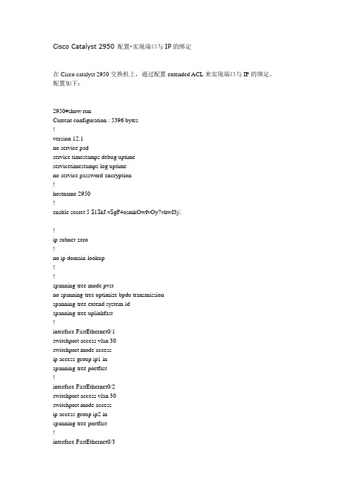
Cisco Catalyst 2950 配置-实现端口与IP的绑定在Cisco catalyst 2950交换机上,通过配置extended ACL来实现端口与IP的绑定。
配置如下:2950#show runCurrent configuration : 5396 bytes!version 12.1no service padservice timestamps debug uptimeservicetimestamps log uptimeno service password-encryption!hostname 2950!enable secret 5 $1$kJ.v$gF4osmkOwfvOy7vkwI3j/.!ip subnet-zero!no ip domain-lookup!!spanning-tree mode pvstno spanning-tree optimize bpdu transmissionspanning-tree extend system-idspanning-tree uplinkfast!interface FastEthernet0/1switchport access vlan 30switchport mode accessip access-group ip1 inspanning-tree portfast!interface FastEthernet0/2switchport access vlan 30switchport mode accessip access-group ip2 inspanning-tree portfast!interface FastEthernet0/3switchport access vlan 30 switchport mode accessip access-group ip3 in spanning-tree portfast!interface FastEthernet0/4 switchport access vlan 30 switchport mode accessip access-group ip4 in spanning-tree portfast!interface FastEthernet0/5 switchport access vlan 30 switchport mode accessip access-group ip5 in spanning-tree portfast!interface FastEthernet0/6 switchport access vlan 30 switchport mode accessip access-group ip6 in spanning-tree portfast!interface FastEthernet0/7 switchport access vlan 30 switchport mode accessip access-group ip7 in spanning-tree portfast interface FastEthernet0/8 switchport access vlan 30 switchport mode accessip access-group ip8 in spanning-tree portfast!interface FastEthernet0/9 switchport access vlan 30 switchport mode accessip access-group ip9 in spanning-tree portfast!interface FastEthernet0/10 switchport access vlan 30 switchport mode accessip access-group ip10 inspanning-tree portfast!interface FastEthernet0/11 switchport access vlan 30 switchport mode accessip access-group ip11 in spanning-tree portfast!interface FastEthernet0/12 switchport access vlan 30 switchport mode accessip access-group ip12 in spanning-tree portfast!interface FastEthernet0/13 switchport access vlan 30 switchport mode accessip access-group ip13 in spanning-tree portfast!interface FastEthernet0/14 switchport access vlan 30 switchport mode accessip access-group ip14 in spanning-tree portfast!interface FastEthernet0/15 switchport access vlan 30 switchport mode accessip access-group ip15 in spanning-tree portfast!interface FastEthernet0/16 switchport access vlan 30 switchport mode accessip access-group ip16 in spanning-tree portfast!interface FastEthernet0/17 switchport access vlan 30 switchport mode accessip access-group ip17 in spanning-tree portfast!interface FastEthernet0/18 switchport access vlan 30 switchport mode accessip access-group ip18 in spanning-tree portfast!interface FastEthernet0/19 switchport access vlan 30 switchport mode accessip access-group ip19 in spanning-tree portfast!interface FastEthernet0/20 switchport access vlan 30 switchport mode accessip access-group ip20 in spanning-tree portfast!interface FastEthernet0/21 switchport access vlan 30 switchport mode accessip access-group ip21 in spanning-tree portfast!interface FastEthernet0/22 switchport access vlan 30 switchport mode access[Page] ip access-group ip22 in spanning-tree portfast!interface FastEthernet0/23 switchport access vlan 30 switchport mode accessip access-group ip23 in spanning-tree portfast!interface FastEthernet0/24 switchport access vlan 30 switchport mode accessip access-group ip24 in spanning-tree portfast!interface GigabitEthernet0/1 switchport mode trunk!interface GigabitEthernet0/2spanning-tree stack-port!interface Vlan1no ip addressno ip route-cacheshutdown!interface Vlan100ip address 192.168.100.22 255.255.255.0 no ip route-cache!ip default-gateway 192.168.100.254ip http server!ip access-list extended ip1permit ip host 192.168.30.1 anyip access-list extended ip10permit ip host 192.168.30.10 anyip access-list extended ip11permit ip host 192.168.30.11 anyip access-list extended ip12permit ip host 192.168.30.12 anyip access-list extended ip13permit ip host 192.168.30.13 anyip access-list extended ip14permit ip host 192.168.30.14 anyip access-list extended ip15permit ip host 192.168.30.15 anyip access-list extended ip16permit ip host 192.168.30.16 anyip access-list extended ip17permit ip host 192.168.30.17 anyip access-list extended ip18permit ip host 192.168.30.18 anyip access-list extended ip19permit ip host 192.168.30.19 anyip access-list extended ip2permit ip host 192.168.30.2 anyip access-list extended ip20permit ip host 192.168.30.20 anyip access-list extended ip21permit ip host 192.168.30.21 anyip access-list extended ip22 permit ip host 192.168.30.22 anyip access-list extended ip23 permit ip host 192.168.30.23 anyip access-list extended ip24 permit ip host 192.168.30.24 anyip access-list extended ip3permit ip host 192.168.30.3 anyip access-list extended ip4permit ip host 192.168.30.4 anyip access-list extended ip5permit ip host 192.168.30.5 anyip access-list extended ip6ip access-list extended ip5permit ip host 192.168.30.5 anyip access-list extended ip6permit ip host 192.168.30.6 anyip access-list extended ip7permit ip host 192.168.30.7 anyip access-list extended ip8permit ip host 192.168.30.8 anyip access-list extended ip9permit ip host 192.168.30.9 any snmp-server community private RO !line con 0line vty 0 4password !@#$%loginline vty 5 15password !@#$%login!!end2950#。

Cisco 2950交换机简要使用说明目录1 概述 (3)2 配置端口 (3)2.1 配置一个端口 (3)2.2 配置一组端口 (4)2.3 配置二层端口 (5)2.3.1 配置端口速率及双工模式 (5)2.4 监控及维护端口 (6)2.4.1 监控端口和控制器的状态 (6)2.4.2 刷新、重置端口及计数器 (6)2.4.3 关闭和打开端口 (7)3 配置VLAN (8)3.1 理解VLAN (8)3.2 可支持的VLAN (8)3.3 配置正常范围的VLAN (9)3.3.1 生成、修改以太网VLAN (9)3.3.2 删除VLAN (10)3.3.3 将端口分配给一个VLAN (11)3.4 配置VLAN Trunks (12)3.4.1 定义trunk允许的VLAN (13)3.4.2 配置Native VLAN(802.1q) (14)3.5 使用VTP (14)3.5.1 VTP管理域设置 (14)3.5.2 VTP中继设置 (15)3.5.3 创建VLAN和分配端口到VLAN (15)4 访问控制(ACL) (15)4.1 以数值命名的ACL (16)4.1.1 创建标准IP ACL (17)4.1.2 创建扩展IP ACL (17)4.2 以字符命名的ACL (18)4.2.1 创建标准IP ACL (19)4.2.2 创建扩展IP ACL (19)4.3 在接口上应用IP ACL (20)5 网络风暴控制 (20)5.1 网络风暴控制设置原则 (20)5.2 设置网络风暴控制参数 (21)5.3 取消网络风暴控制 (21)6 使用STP实现负载均衡 (21)6.1 使用STP端口权值的负载均衡 (22)6.2 配置STP路径值的负载均衡 (24)1 概述本使用说明只包括日常使用的有关命令及特性,其它未涉及的命令及特性请参考英文的详细配置手册。
cisco 2950是只支持二层特性的交换机。

2950交换机的详细配置switch> 用户模式1:进入特权模式 enableswitch> enableswitch#2:进入全局配置模式 configure terminalswitch> enableswitch#configure terminalswitch(conf)#3:交换机命名 hostname aptech2950 以aptech2950为例switch> enableswitch#configure terminalswitch(conf)#hostname aptch-2950aptech2950(conf)#4:配置使能口令 enable password cisco 以cisco为例switch> enableswitch#configure terminalswitch(conf)#hostname aptch2950aptech2950(conf)# enable password cisco5:配置使能密码 enable secret ciscolab 以cicsolab为例switch> enableswitch#configure terminalswitch(conf)#hostname aptch2950aptech2950(conf)# enable secret ciscolab6:设置虚拟局域网vlan 1 inte***ce vlan 1switch> enableswitch#configure terminalswitch(conf)#hostname aptch2950aptech2950(conf)# inte***ce vlan 1aptech2950(conf-if)#ip address 192.168.1.1 255.255.255.0 配置交换机端口ip和子网掩码aptech2950(conf-if)#no shut 使配置处于运行中aptech2950(conf-if)#exitaptech2950(conf)#ip default-gateway 192.168.254 设置网关地址7:进入交换机某一端口 inte***ce fastehernet 0/17 以17端口为例switch> enableswitch#configure terminalswitch(conf)#hostname aptch2950aptech2950(conf)# inte***ce fastehernet 0/17aptech2950(conf-if)#8:查看命令 showswitch> enableswitch# show version 察看系统中的所有版本信息show inte***ce vlan 1 查看交换机有关ip 协议的配置信息show running-configure 查看交换机当前起作用的配置信息show inte***ce fastethernet 0/1 察看交换机1接口具体配置和统计信息show mac-address-table 查看mac地址表show mac-address-table aging-time 查看mac地址表自动老化时间9:交换机恢复出厂默认恢复命令switch> enableswitch# erase startup-configureswitch# reload10:双工模式设置switch> enableswitch#configure terminalswitch2950(conf)#hostname aptch-2950aptech2950(conf)# inte***ce fastehernet 0/17 以17端口为例aptech2950(conf-if)#duplex full/half/auto 有full , half, auto 三个可选项11:cdp相关命令switch> enableswitch# show cdp 查看设备的cdp全局配置信息show cdp inte***ce fastethernet 0/17 查看17端口的cdp配置信息show cdp traffic 查看有关cdp包的统计信息show cdp nerghbors 列出与设备相连的cisco设备12:csico2950的密码恢复拔下交换机电源线。
2950交换机简明配置维护手册目录说明 (3)产品特性 (3)配置端口 (4)配置一组端口 (4)配置二层端口 (6)配置端口速率及双工模式 (6)端口描述 (7)监控及维护端口 (8)监控端口和控制器的状态 (8)刷新、重置端口及计数器 (10)关闭和打开端口 (10)配置VLAN (11)理解VLAN (11)可支持的VLAN (12)配置正常范围的VLAN (12)生成、修改以太网VLAN (13)删除VLAN (14)将端口分配给一个VLAN (15)配置VLAN Trunks (16)使用STP实现负载均衡 (19)配置Cluster (23)说明本手册只包括日常使用的有关命令及特性,其它未涉及的命令及特性请参考英文的详细配置手册。
产品特性2950是只支持二层的交换机支持VLAN•到250 个VLAN•支持VLAN ID从1到4094(IEEE 802.1Q 标准)•支持ISL及IEEE 802.1Q封装安全•支持IOS标准的密码保护•支持标准及扩展的访问列表来定义安全策略•支持基于VLAN的访问列表监视•交换机LED指示端口状态•SPAN及远端SPAN (RSPAN) 可以监视任何端口或VLAN的流量•内置支持四组的RMON监控功能(历史、统计、告警及事件)配置端口配置一组端口当使用interface range命令时有如下的规则:•有效的组范围:o vlan从1 到4094o fastethernet槽位/{first port} - {last port}, 槽位为0o gigabitethernet槽位/{first port} - {last port},槽位为0o port-channel port-channel-number - port-channel-number, port-channel号从1到64•端口号之间需要加入空格,如:interface range fastethernet 0/1 – 5是有效的,而interface range fastethernet 0/1-5是无效的.•interface range命令只能配置已经存在的interface vlan•所有在同一组的端口必须是相同类别的。
一、Cisco 2950交换机基本配置switch>switch>enableswitch#switch#vlan database(进入vlan维护模式)switch(vlan)#vlan 2 name vlan2(给vlan 2命名为vlan2)switch(vlan)#vlan 4 name vlan4(给vlan 4命名为vlan4)switch(vlan)#exit(这里要注意一下,要打入exit退出才有效,不能用ctrl+z或end直接退出,因为这么不能使配置生效!)switch#show vlan(查看vlan的配置,默认有vlan1)switch#configure terminal(进入全局配置模式)switch(config)#interface f0/1(进入fastethernet0/1接口配置模式)switch(config-if)#switchport mode access(这步可以省略)switch(config-if)#switchport access vlan 2(把该接口划分到vlan2,记得vlan2之间有空格)switch(config-if)#no shutdown(激活端口)switch(config-if)#exitswitch(config)#interface f0/2switch(config-if)#switchport mode accessswitch(config-if)#switchport access vlan 4switch(config-if)#no shutdownswitch(config-if)#exitswitch(config)#interface f0/3switch(config-if)#switchport mode trunk(设置此口为中继模式)switch(config-if)#no shutdownwitch(config-if)#exit(这里可以直接用ctrl+z或end直接退出到特权模式)原文出自【比特网】,转载请保留原文链接:/61/12139561.shtml三.给PC1,PC2设置好IP地址,然后用ping命名令测试!1、配置IP地址交换机要能够被网管,必须给它标识一个管理IP地址,默认情况下CISCO交换机的VLAN 1为管理VLAN,为该VLAN配上IP 地址,交换机就可以被网管了。
Using Express Setup on a Catalyst 2950 Series Switch for Initial InstallationDocument ID: 45383ContentsIntroductionPrerequisitesRequirementsComponents UsedConventionsStarting Express SetupEntering the Express Setup Configuration ParametersRequired ParametersOptional ParametersSaving the New ConfigurationReset the PC's IP Address using DHCPVerifying the Switch's IP AddressTroubleshootingFaulty CableIP Addressing MisconfigurationSwitch is not Cabled to the Correct SegmentPC was not Restored to its Original IP AddressThe Switch's Configuration File was not SavedClearing the Switch IP Address and ConfigurationAppendix A: Setting up the IP Address on your PC to use Express SetupChanging your PC to use DHCPChanging the Static IP Address to 10.0.0.2 ManuallyChanging the Static IP Address to the Original ValuesAppendix B: Where To Go NextRelated InformationIntroductionThis document explains how to use the new Express Setup feature on the Catalyst 2950 series switches to configure a new switch or a switch that has had its configuration file erased.Express Setup is available in Cisco IOS® Software Releases 12.1(14)EA1 and later. This feature allows you to set basic configuration parameters such as IP address, default gateway, host name, and the system, enable mode (configuration), and Telnet passwords.If you are already know how to configure your Catalyst 2950 series switch with the basic configuration parameters described above using the Command Line Interface (CLI) over a console (terminal) session on your PC, you do not need to read this document unless you would prefer to use Express Setup to configure these parameters.Note: This document applies to all of the Catalyst 2950 series switches except the Catalyst 2950 Long Reach Ethernet (LRE) and the Catalyst 2955.PrerequisitesIf you do not want manage the switch with TCP/IP based applications such as Cisco Cluster Management Suite (CMS) or Telnet, you do not need to configure any settings on it. The default configuration in the switch has all ports enabled with auto sensing for the speed and duplex settings. The ports are all in VLAN 1. This allows devices connected to any of the ports to communicate with each other.You can manage the switch using a console connection from the serial port on a PC. The correct serial cable is supplied with the switch.Please note that Cisco recommends using TCP/IP to manage your switch. This document explains how to configure your switch using Express Setup to be managed via TCP/IP.Before using Express Setup to configure a switch, refer to the Catalyst 2950 Desktop Switch Hardware Installation Guide, May 2003, which discusses some of the following topics.•Removing the switch and AC power cord from the shipping container•Getting an Ethernet (Category 5) straight−through cable to connect the switch to your PC orworkstation•Powering on the switchRequirementsThis procedure requires that your PC has an IP address of 10.0.0.2 with a mask of 255.255.255.0 in order to configure the switch. If your PC does not use Dynamic Host Configuration Protocol (DHCP), you have the option of manually configuring this address or temporarily changing your PC to use DHCP so that it can receive the 10.0.0.2 address from the temporary DHCP server that runs on the switch during Express Setup. Refer to Appendix A: Setting up the IP Address on your PC to use Express Setup for more information.Your Catalyst 2950 switch must be running Cisco IOS® Software Release 12.1(14)EA1 or later to use Express Setup.Your switch must not have a configuration file. If you want to use Express Setup to reconfigure a switch that was previously deployed and already has a configuration in its file system see the Clearing the Switch IP Address and Configuration section of this document for instructions on deleting the existing configuration. Cisco IOS software for the Catalyst 2950 can be downloaded from the Cisco Catalyst 2950 Software Center ( registered customers only) .If you need help upgrading your switch, refer to the following documentation.•Upgrading Software Images on Catalyst 2950 and 2955 Series Switches Using the Command LineInterface•Working with the Cisco IOS File System, Configuration Files, and Software Images Working with the Flash File SystemIf you have a problem upgrading your switch, refer to Recovering Catalyst 2950, 2955, and 3550 Series Switches from a Corrupted or Missing Image.Components UsedThe information in this document is based on the Catalyst 2950 Switch running Cisco IOS Software Release 12.1(14)EA1.The information presented in this document was created from devices in a specific lab environment. All of the devices used in this document started with a cleared (default) configuration. If you are working in a live network, ensure that you understand the potential impact of any command before using it.ConventionsFor more information on document conventions, see the Cisco Technical Tips Conventions.Starting Express SetupThis task explains how to use the browser based Express Setup utility introduced in Cisco IOS Software Release 12.1(14)EA1 to set up and configure the switch. You assign the IP information (IP address, subnet mask, and default gateway) for the Management VLAN (VLAN 1 by default) so that the switch can be managed by a PC using TCP/IP.Caution: Do not start Express Setup when there are any devices connected to the switch or connect a switch that is already in Express Setup mode to any device other than the PC or workstation that is being used to configure it. The switch acts as a DHCP server during the Express Setup procedure, and only the PC or workstation connected to the switch after Express Startup is started should receive a DHCP address from the switch.Note: The illustrations in this section show the Catalyst 2940 switch but the Mode button, LEDs, and switch ports are similar on the non−LRE Catalyst 2950 switch.Before starting Express Setup, verify that the switch has passed the power−on self−test (POST). The SYST and STAT LEDs should be on and green if the switch has successfully passed POST. For information about troubleshooting a POST failure, refer to the Catalyst 2950 Desktop Switch Hardware Installation Guide, May 2003. You cannot start Express Setup until POST has completed.Follow these steps to start the Express Setup program.1.Verify that no devices are connected to the switch.Press and hold the Mode button, as shown in Figure 1, until the four LEDs next to the Mode button2.turn green.This takes approximately 2 seconds.Note: This only works on switches that do not have a configuration file in their file system.Figure 11 − Mode ButtonWhen the four LEDs turn green, release the Mode button.3.Note: If all of the Mode LEDs begin to blink after you have held the Mode button for 2 seconds or you cannot get the four LEDs to remain lit, a configuration already exists on the switch. In this case the switch cannot enter Express Setup mode. See the section of this document Clearing the Switch IP Address and Configuration for the instructions on deleting a configuration file from a switch.Connect the Ethernet cable (not included) to a 10/100 Ethernet port on the front panel of the switch,as shown in Figure 2.Caution: Do not connect the switch to any device other than the PC being used to configure it.Figure 21 − Switch♦ 2 − Ethernet cable♦ 3 − PC or workstation♦ 4. Connect the other end of the cable to the Ethernet port on the PC and verify that the port status LEDs on both connected Ethernet ports are green.5. Wait approximately 30 seconds after the port LEDs turn green, and launch a web browser on your PC.6. If you are using DHCP on your PC, you need to obtain the 10.0.0.2 IP address from the switch now.Do one of the two following options depending on the operating system on your PC.If you have manually configured your PC to use 10.0.0.2, skip this step and proceed to step 8.Windows 95/98/ME:Select Start > Run and enter winipcfg .The WINIPCFG application opens as shown in Figure 3.Note: You must select the NIC that you have connected to the switch in the WINIPCFGwindow before continuing this task.Figure 3a. 7.If the IP address is already 10.0.0.2, proceed to step 8.Click Release All .b. Click Renew All .When the IP address has changed to 10.0.0.2, proceed to step 8.c. Windows 2000/XPSelect Start > Run and enter CMD to open a command prompt window.a. Enter the command ipconfig /release at the prompt.b. Enter the command ipconfig /renew at the prompt.c. Enter the command ipconfig /all at the prompt to display the current settings.When the IP address has changed to 10.0.0.2, proceed to step 8.d. Enter the IP address 10.0.0.1, as shown in Figure 4 in the browser, and press Enter .Figure 4If the Express Setup home page appears, as shown in Figure 5, proceed to the next task Entering the Express Setup Configuration Parameters.Figure 58.Consider the following issues if the Express Setup home page does not appear in your browser.•Are you running Cisco IOS Software Release 12.1(14)EA1 or later on the switch?If not, upgrade it now.•Did you release and renew the IP address on your PC using DHCP or manually configure its address to 10.0.02?If not do so now. See Appendix A: Setting up the IP address on your PC to use Express Setup forhelp.•Did you wait 30 seconds after connecting the switch and PC or workstation before entering the IPaddress in your browser?If not, wait 30 seconds and re−enter 10.0.0.1 in the browser, and press Enter.•Did you enter the wrong address in your web browser, or is there an error message displayed in thebrowser window?Re−enter 10.0.0.1 in the browser, and press Enter.•Did you connect a crossover instead of a straight−through Ethernet cable between an Ethernet port of the switch and the Ethernet port of the PC, as shown Figure 3?If not, reconnect the cable to the Ethernet port on the switch and PC. Wait 30 seconds before entering10.0.0.1 in the browser.Did you verify that POST successfully ran before starting Express Setup?•If not, make sure that only the SYST and STAT LEDs are green before pressing the Mode button to begin Express Setup.•Did all of the Mode LEDs begin to blink after you have held the Mode button for 2 seconds?If they did, a configuration already exists on the switch and the switch cannot go into Express Setup mode. Release the button. For more information, see the section titled Clearing the Switch IP Address and Configuration.Entering the Express Setup Configuration ParametersThis task explains the required and optional parameters in the Express Setup home page as shown in Figure 5.Caution: Do not select the Save option at the bottom of the configuration page until you have filled out all of the parameters that you want to include in the startup configuration.Note: The parameters that you enter on this page are not validated until you select the Save option. The error messages that appear when you attempt to save a configuration that has errors are shown below in the section that applies to each parameter.Required ParametersThe following parameters are required to allow a PC using TCP/IP to manage the switch.Enter the IP address of the switch in the IP Address field.1. Click the drop−down arrow in the IP Subnet Mask field, and select an IP Subnet Mask.2. Enter the IP address for the default gateway in the Default Gateway field.A gateway (router or dedicated network device) is a system that allows IP connectivity betweendevices on different IP subnets. If your PC and your switch have IP addresses from different subnets,you must enter the correct default gateway for the switch in its configuration.If you do not enter a default gateway, the following warning message appears (Figure 6) when you try to save the configuration.Figure 6If you enter a gateway address that is on a different subnet than the switch, the following warning message appears (Figure 7) when you try to save the configuration.Figure 73. Enter the password in the Switch Password field.The password can be from 1 to 25 alphanumeric characters, can start with a number, is case sensitive,allows embedded spaces, but does not allow embedded spaces at the beginning or end.Cisco recommends that you set a switch password. Blank passwords are a security risk.4.If you do not type the same password in both fields, the following error message appears (Figure 8)when you try to save the configuration.Figure 8Enter the password again in the Confirm Switch Password field.5. Optional ParametersThe following parameters are optional if you want to use Cluster Management Suite to manage the switch.Note: If you would like to be able to Telnet to the switch for configuration and or management tasks, you must enter a value in the Telnet Password field.Enter a host name for the switch in the Host Name field.The host name is limited to 31 characters and embedded spaces are not allowed.1. Enter the name of your system contact in the System Contact field.This identifies the system administrator for the switch or network.2. Enter your system location in the System Location field.This identifies the physical location of the switch.3. Click Enable in the Telnet Access field if you are going to use Telnet.If you enable Telnet access, you must enter a Telnet password.Enter a password in the Telnet Password field.The Telnet password can be from 1 to 25 alphanumeric characters, is case sensitive, allowsembedded spaces, but does not allow embedded spaces at the beginning or end.a. Enter the Telnet password again in the Confirm Telnet Password field.If you do not type the same password in both fields, following error message appears (Figure9) when you try to save the configuration.Figure 9b. 4. Click Enable to configure Simple Network Management Protocol (SNMP).5.Enable SNMP only if you plan to manage switches by using Cisco Works or another SNMP−based network−management system.Note: If you do not have an SNMP management application in your network, you do not have to configure the SNMP parameters.If you enable SNMP, you must enter a community string in either the SNMP Read Community field,the SNMP Write Community field, or both. SNMP community strings authenticate access to MIB objects. Embedded spaces are not allowed in SNMP community strings. If you set the SNMP read community, users can access MIB objects, but cannot modify them. If you set the SNMP write community, users can access and modify MIB objects.Your completed configuration will resemble Figure 10.Figure 10Saving the New ConfigurationUse the following procedure to save the new configuration.Click Save to save your settings to the switch, or click Cancel to clear your settings.If you decide to save the configuration, the following warning message appears (Figure 11). This is a normal message. It does not indicate that your configuration has an error.In this document, the switch's IP address was changed to 10.1.0.254 as shown in Figure 10 and Figure 11.Figure 111.Click OK to save the configuration.After you save your settings, the switch exits Express Setup mode.Your switch is now configured with the new IP address.You will see two additional information popups.A popup (Figure 12) appears letting you know that your browser's current page is being redirected to the new IP address on the switch. This popup automatically closes.Figure 12In most cases, this redirect fails and your browser shows an error indicating that the page cannot be found. The reason that this fails is that your PC still has its address as 10.0.0.2 255.25.255.0 at this point. The only way that this redirect works is if you configured the switch with the IP address10.0.0.1 255.255.255.0 (the same address that was used on the switch during Express Setup) or an IP address between 10.0.0.3 255.255.255.0 and 10.0.0.254 255.255.255.0.You will also see the Help popup as shown in Figure 13.Figure 13 (Part 1)2.Figure 13 (Part 2)Reconnect your PC's Ethernet cable to the device it was connected to before you started the Express3.Setup procedure.Wait for the link LEDs to indicate that the link is active and then proceed to the next task.Reset the PC's IP Address using DHCPThis step explains how to reset your PC's IP address if it is using DHCP.If you are using a static (manually) entered IP address, do not perform this step. You need to restore the original IP address for the PC using the procedure provided in Appendix A: Setting up the IP Address on your PC to use Express Setup.If you are using DHCP on your PC, you need to obtain an IP address from the DHCP server on the network again.Do one of the two following options depending on the operating system on your PC.Windows 95/98/MESelect Start > Run and enter winipcfg.a.The WINIPCFG application opens as shown in Figure 14.Caution: You must select the NIC that you have connected to the switch in the WINIPCFGwindow before continuing this task.Figure 14Click Release All .b. Click Renew All .When the PC's IP address has changed to an IP address for the subnet that the PC is attached to, you have completed this task. Proceed to the next task Verifying the Switch's IP Address.c. Windows 2000/XPSelect Start > Run and enter CMD to open a command prompt window.a. Enter the command ipconfig /release at the prompt.b. Enter the command ipconfig /renew at the prompt.c. Enter the command ipconfig /all at the prompt.This displays the current settings.When the PC's IP address has changed to an IP address for the subnet that the PC is attached to, you have completed this task. Proceed to the next task Verifying the Switch's IP Address.d. Verifying the Switch's IP AddressAfter you have installed the switch in your network, follow these steps to verify the IP address configured on your switch by loading the main configuration home page.Launch a web browser on your PC.Note: You must have reconnected your PC to its original location and restored its IP address before continuing this task.1. Enter the IP address of your switch in the browser's Location field and press Enter .The switch home page should appear, as shown in Figure 15.Figure 152.If the switch's home page doesn't appear, refer to the Troubleshooting section below.TroubleshootingThe Express Setup process that you already went through verified that the switch has the correct configuration home page files on it. It also verified that the switch is running the web server to allow a PC to access the files from a browser. If the browser on your PC is unable to load the switch's configuration home page after you moved the switch to its final location, the most likely problems are:•A faulty cable•An IP addressing misconfiguration•The switch is not cabled to the correct segment•The PC was not restored to its original IP address•The switch's configuration file was not savedFaulty CableVerify that the LED on the port that the switch uses to connect to the subnet its default gateway is on green. If it is not, try using a different cable.If the port is connected to another switch or a hub, you need to use an Ethernet crossover patch cable, not a standard straight patch cable.IP Addressing MisconfigurationThe most common reason that you cannot connect to the switch's configuration home page is that there is a router (gateway) between your PC and the switch and either the switch or your PC has an incorrect default gateway configured.1.Test access from your PC to other devices that are not on its local subnet.For instance, if the PC can download email, browse the Internet, or browse a corporate web site on the internal network, then it's configuration is probably correct.Find a PC on the same IP subnet as the switch. Try to load the switch's configuration home page from2.this PC.If this works, then it is possible that you entered the incorrect default gateway IP address on theswitch. You can verify this by finding the default gateway on the PC that you used in this test. Useeither the winipcfg command (Win95/98/ME) or the ipconfig /all command (Win2000/XP) to display the IP gateway address on the PC.If the default gateway on the PC is different than the one you entered on the switch, you can change the switch's default gateway using the ip default−gateway ip_address command over either theconsole port or a Telnet session.Switch > enableSwitch#configure terminalSwitch(config)#ip default−gateway ip_addressSwitch(config)#exitSwitch#copy running−config startup−configWhere ip_address is the correct IP address of the gateway for the switch.If you are unable to start either a console session or a Telnet session with the switch, you will have to repeat the Express Setup procedure after clearing the switch's configuration. See the section Clearing the Switch IP Address and Configuration.Switch is not Cabled to the Correct SegmentVerify that the switch is connected to the network that uses the IP subnet that you assigned to the switch.PC was not Restored to its Original IP AddressVerify that you returned your PC to its original IP configuration.If your PC was using DHCP before you started configuring the switch, refer to the section Reset the PC's IP Address using DHCP.If your PC was using a static address, refer to Appendix A: Setting up the IP Address on your PC to use Express Setup − Static IP Addresses.The Switch's Configuration File was not SavedIt is possible that the switch did not save its configuration properly after you clicked Save on the configuration screen. Proceed to the section Clearing the Switch IP Address and Configuration.Clearing the Switch IP Address and ConfigurationIf you have configured a new switch with a wrong IP address, or all the switch LEDs start blinking when you are trying to enter Express Setup mode, you can clear the IP address that is configured on the switch.Caution: This procedure clears the IP address and all configuration information stored on the switch. Do not follow this procedure unless you want to completely reconfigure the switch.To clear the IP address and the switch configuration information, follow these steps.1.Press and hold the Mode button, as shown in Figure 2.The switch LEDs begin blinking after about 2 seconds.2.Continue holding down the Mode button.The LEDs stop blinking after 8 additional seconds and then the switch reboots.3.Return to Starting Express Setup.Appendix A: Setting up the IP Address on your PC to use Express SetupIf your PC is using a statically assigned IP address, you can either convert it to use DHCP temporarily so that it can obtain the 10.0.0.2 IP address from the switch during Express Setup, or you can configure it to use 10.0.0.2 manually.•Changing your PC to use DHCP•Changing the Static IP Address to 10.0.0.2 Manually•Changing the Static IP Address to the Original ValuesChanging your PC to use DHCPUse the following procedure to change your PC to use DHCP.1.Select Start > Settings > Control Panel.2.Double−click on Network and Dial−up Connections.Double−click on the icon that represents your LAN connection.3.This is typically Local Area Connection. The following window (Figure 16) appears.Figure 164.Click Properties.The following window (Figure 17) appears.Figure 17Scroll down and select Internet Protocol (TCP/IP) and then click Properties .The following window (Figure 18) appears.Figure 185.Change both settings to the automatic options as shown in Figure 18.6. Click OK to close the current window.7. Click OK to close the current window.8. Click Close to close the current window.Your PC is now ready to use DHCP.Note: If you are using Win95/98/ME, you will be prompted to reboot your PC.9. Changing the Static IP Address to 10.0.0.2 ManuallyUse the following procedure to change the static IP address to 10.0.0.2 manually.Select Start > Settings > Control Panel .1. Double−click on Network and Dial−up Connections .2. Double−click on the icon that represents your LAN connection.This is typically Local Area Connection . The following window (Figure 19) appears.Figure 193.Click Properties .The following window (Figure 20) appears.Figure 204. Scroll down and select Internet Protocol (TCP/IP) and then click Properties .The following window (Figure 21) appears.Figure 215.Note: Make a note of the current settings so that you can repeat this task later to restore them after you have configured the switch.Change the IP address parameters so that they match the values shown in Figure 22.Figure 226.Click OK to close the current window.7. Click OK to close the current window.8. Click Close to close the current window.Your PC is now ready to use 10.0.0.2.Note: If you are using Win95/98/ME, you will be prompted to reboot your PC.9. Changing the Static IP Address to the Original ValuesUse the following procedure to change the static IP address to the original values.Select Start > Settings > Control Panel .1. Double−click on Network and Dial−up Connections .2. Double−click on the icon that represents your LAN connection.This is typically Local Area Connection . The following window (Figure 23) appears.Figure 233.Click Properties .The following window (Figure 24) appears.Figure 244. Scroll down and select Internet Protocol (TCP/IP) and then click Properties .The following window (Figure 25) appears.Figure 255.Caution: Make a note of the current settings so that you can repeat this task later to restorethem after you have configured the switch.Change the IP address parameters so that they match the values that you noted down before you changed them.Caution: Do not use the values shown in Figure 26. They are shown here because they were the original values on the PC that was used to create this document. You must re−enter the original values from your PC.Figure 266.7.Click OK to close the current window.8.Click OK to close the current window9.Click Close to close the current window.Your PC is now ready to use 10.0.0.2.Note: If you are using Win95/98/ME, you will be prompted to reboot your PC.Appendix B: Where To Go NextAfter you have successfully deployed your switch, refer to the following documentation for additional configuration options.•Getting Started with Cluster Management Suite (CMS)•Catalyst 2950 and Catalyst 2955 Switch Software Configuration Guide, 12.1(14)EA1Related InformationLAN Switching Technology Support••Catalyst LAN and ATM Switches Product Support•Technical Support − Cisco SystemsContacts & Feedback | Help | Site Map© 2009 − 2010 Cisco Systems, Inc. All rights reserved. Terms & Conditions | Privacy Statement | Cookie Policy | Trademarks of Cisco Systems, Inc.Updated: Nov 17, 2007Document ID: 45383。
Cisco2950交换机安装配置、故障排除手册网络配置 2008-09-12 16:45 阅读121 评论0字号:大大中中小小目录第一部分交换机安装. 21.1 安装前相关考虑. 21.2 在机架上固定交换机. 21.3 安装GBIC模块. 41.4 安装连接线缆. 5第二部分交换机基本配置. 82.1 加电后首次配置. 82.2 通过浏览器配置交换机. 92.3 通过CONSOLE口进入命令行配置. 11第三部分高级配置. 20第四部分安全配置. 22第五部分故障排除. 275.1 检查设备状态指示灯. 275.2 检查配置及相关信息. 295.3 已知的问题及解决方式. 33第六部分常见问题. 35第一部分交换机安装1.1 安装前相关考虑Warning :To prevent the switch from overheating, do not operate it in anarea that exceeds the maximum recommended ambient temperature of 113\xb0 F (45\xb0 C). To prevent airflow restriction, allow at least 3 inches (7.6 cm) of clearance around the ventilation openings。
Warning:When installing the unit, the ground connection must always bemade first And disconnected last.1.2 在机架上固定交换机l Attaching Brackets (Front Panel Forward)l Attaching Brackets (Rear Panel Forward)l Mounting the Switch in a Rackl Attaching the Optional Cable Guide1.3 安装GBIC模块l Installing a 1000BASE-X GBIC Module in the Switchl Installing a 1000BASE-T GBIC Module in the Switchl Installing a GigaStack GBIC Module in the Switch1.4 安装连接线缆注意:交换机端口速率、双工的设置Ø Let the ports autonegotiate both speed and duplex.Ø Set the port speed and duplex parameters on both ends of the connection.When connecting to workstations, servers, routers, and Cisco IP Phones, connect a straight-through Category 5 cable to an RJ-45 connector on the front panel.When connecting to switches or repeaters, use a crossover Category 5 cable。
l Connecting to a 10/100/1000 Switch PortThe port LED is amber while Spanning Tree Protocol (STP) discovers the topology and searches for loops. This takes about 30 seconds, and then the port LED turns green.If the port LED does not come on, the device at the other end might not be turned on, or there might be a cable problem or a problem with the adapter installed in the attached device.l Connecting to a 1000BASE-X PortCaution : Do not remove the rubber plugs from the fiber-optic port or the rubber caps from the fiber-optic cable until you are ready to connect the cable. The plugs and caps protect the fiber-optic port and cable from contamination and ambient light.l Connecting to a 1000BASE-T Portl Connecting to a GigaStack Portl Connecting to the Console PortAttach the supplied RJ-45-to-DB-9 female DTE adapter to a PC, or attach an appropriate adapter to the terminal.Insert the other end of the supplied rollover cable in the attached adapter.Boot the terminal-emulation program if you are using a PC or terminal.第二部分交换机基本配置CISCO2950-24/48 EI 交换机配置涉及到加电后首次配置、通过浏览器进行配置以及通常的基于CLI命令行配置等方面。
2.1 加电后首次配置Use the supplied rollover cable and DB-9 adapter to connect a PC to the switch console port. If you want to connect the switch console port to a terminal, you need to provide a RJ-45-to-DB-25 female DTE adapter.The PC or terminal must support VT100 terminal emulation. The terminal-emulation software—frequently a PC application such as Hyperterminal or Procomm Plus—makes communication between the switch and your PC or terminal possible during the setup program.Configure the baud rate and character format of the PC or terminal to match these console port default characteristics:Ø 9600 baudØ 8 data bitsØ 1 stop bitØ No parityUsing the supplied rollover cable, insert the RJ-45 connector into the console port。
Note:If the switch will be a cluster member managed through the IP address of the command switch, it is not necessary to assign IP information or a password. If you are configuring the switch as a standalone switch or as a command switch, you must assign IP information.Would you like to enter the initial configuration dialog? [yes/no]: yesWould you like to enter basic management setup? [yes/no]: yesEnter host name [Switch]: xxxxOn a command switch, the host name is limited to 28 characters; on a member switch to 31 characters. Do not use -n, where n is a number, as the last character in a host name for any switch. Enter enable secret: xxxxThe password can be from 1 to 25 alphanumeric characters, can start with a number, is case sensitive, allows spaces, but ignores leading spacesEnter enable secret: xxxxEnter virtual terminal password: xxxxEnter interface name used to connect to the management network from the above interface summary: vlan 1Configuring interface vlan 1:Configure IP on this interface? [yes]: yesIP address for this interface: xxxxSubnet mask for this interface [255.0.0.0]: xxxxWould you like to enable as a cluster command switch? [yes/no]: 视具体情况定,一般,一个堆叠中仅有一台交换机需要配置为命令交换机Enter cluster name: xxxxThe cluster name can be 1 to 31 alphanumeric characters, dashes, or underscores.2.2 通过浏览器配置交换机例如,通过CMS可以方便的配置集群,方便全网连入集群的交换机的管理。