汽车人机工程标准
- 格式:pdf
- 大小:6.19 MB
- 文档页数:36
汽车人机工程标准汽车人机工程标准指的是一系列规范和准则,用于指导汽车设计师在designing、developing、testing and manufacturing汽车时如何考虑人类的生理、心理和情感需求,以确保汽车的使用和操作更加舒适、高效和安全。
汽车人机工程标准是全球范围内的一个重要问题,每个国家在汽车人机工程标准方面都有自己的潜在可能已经制定或者正在制定的标准。
在本文中,我们将讨论汽车人机工程标准的定义、原则和意义,以及它对汽车工业的影响和未来发展趋势。
定义:汽车人机工程标准是基于人体工程学原理,以及人力学、心理学、生理学和感官科学的理论,专门制定的标准,旨在提高汽车的设计质量和使用价值。
汽车人机工程标准涵盖的范围非常广泛,包括但不限于驾驶员的安全和舒适性、显示屏和控制面板的易用性、车门和窗户的操作等。
原则:汽车人机工程标准有一些重要原则,这些原则是基于人体工程学和以人为本的原则。
1. 以人为本的设计思想:这意味着,在设计汽车时,必须优先考虑汽车使用者的需求和期望,确保汽车的使用更加自然、舒适和高效。
这是一个非常重要的原则,也是汽车人机工程标准的所有原则中最基本的一个。
2. 最大程度满足驾驶员的需求和期望:汽车人机工程标准中指出,汽车设计应该尽可能满足驾驶员的需求和期望。
这包括但不限于汽车内部的操作系统、音响和通信设备,以及它们与驾驶员的互动方式的设计等。
3. 稳定和可靠的设计:汽车人机工程标准强调稳定和可靠的设计,这是为了确保汽车的安全性和舒适性。
这涵盖了各种方面,包括汽车的框架、刹车、悬挂系统以及安全装置等。
意义:遵循汽车人机工程标准的设计,可以给消费者带来一系列实实在在的好处:1. 提供更加舒适富有感官体验的驾驶体验:通过遵循汽车人机工程标准,设计者可以创造出更加符合人类工程学原理的车辆。
这意味着驾驶员不仅可以享受使用车辆所带来的愉悦,而且还能够避免身体的疲劳和不适感。
2. 提高驾驶员的安全性:汽车人机工程标准考虑了车内和车外的各种安全因素,包括汽车的刹车、悬挂、气囊系统等等,这将帮助消费者更加安全地驾驶汽车。

汽车人机工程标准范本(doc 36页)人机舒适性要求XXXXXXXXXXXXXXXXXXXXXXXXXXXXXXXXXXXXXXXXXX XXXXXXXXXXXXXXXXXXXXXXXXXXXXXXXXXXXXXXXXXXXXX XXXXXXXXXXXX。
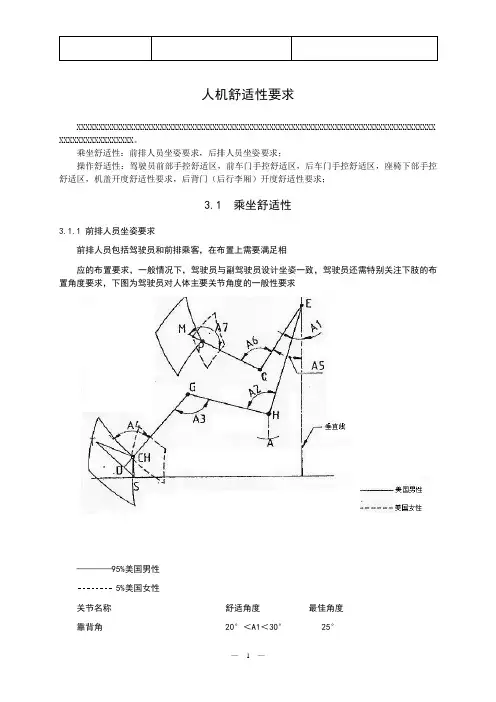
乘坐舒适性:前排人员坐姿要求,后排人员坐姿要求;操作舒适性:驾驶员前部手控舒适区,前车门手控舒适区,后车门手控舒适区,座椅下部手控舒适区,机盖开度舒适性要求,后背门(后行李厢)开度舒适性要求;3.1 乘坐舒适性3.1.1 前排人员坐姿要求前排人员包括驾驶员和前排乘客,在布置上需要满足相应的布置要求,一般情况下,驾驶员与副驾驶员设计坐姿一致,驾驶员还需特别关注下肢的布置角度要求,下图为驾驶员对人体主要关节角度的一般性要求CH:踝关节 85°<A4<110° 87°E:肩部点 25°<A5<60°C:肘关节 80°<A6<165°P:腕关节 170°<A7<190°M:指关节T: A点·舒适驾驶姿态-H点根据舒适驾驶姿态进行确定,不同车型的空间、坐姿角度的具体要求如下表所示。
表对于不同车型来说座椅靠背角度一般:25°为最佳舒适状态,靠背角度也可以根据实际需要做相应的调整;踝关节角度一般:87°为最佳舒适状态,关节角度也可以根据实际需要做相应的调整。
·方向盘与踏板之间的关系-方向盘和油门踏板位置根据95%美国男性四肢的舒适角度进行确定图·方向盘中心与H点的间距-纵向长度:405-415mm-垂直高度:370-380mm·方向盘下端与座椅垫之间的关系-我们称之为方向盘间隙-方向盘间隙:最小165mm·座椅调节滑轨的行程包括最前位置和最后位置。
-最前位置:5%的美国女性-最后位置:95%的美国男性*如果是大中型汽车,H点可以位于最后位置的前方表-座椅调节滑轨倾斜角:3°-5°·头部间隙-顶盖装饰板与驾驶员视点之间的高度:200mm -230mm·视觉-确定H点应在考虑前后视野的基础上寻求良好的视觉效果3-2)横向H点位置·应考虑以下因素:-内部乘员宽度-车顶纵梁(横向头部间隙)-方向盘-踏板-等等·内部乘员宽度-肩部空间和臀部空间-考虑到车门内饰和副仪表板的有效空间表·H点位置表·横向头部间隙表·方向盘和踏板踏板的分类:手动挡踏板和制动档踏板手动挡踏板的外形尺寸制动档踏板的外形尺寸油门踏板、制动踏板、离合踏板的相对位置的确定图*SgRP( 座椅参考点): H点踏板间距(mm)踏板高度差(mm)分类C B *1)A*2)A-BB-C 油门-刹车刹车-离合器设70-80 40-50 最60-70 70-80 30-40 0-计指南小1655注:*1) 右置: 最小155;*2) 右置: 同样概念说明:1.θ1 1°- 2°(正常:1.5 °)L ( 方向盘与H点在平面上的长度): 0-10mm 注:*2 H点为座椅调节范围尺寸代码①(此尺寸仅供参考)②③④⑤AHP (油门踪点)4.后H点·如果是紧凑型和小型轿车,应考虑到乘客空间比后乘客厢更为重要。

汽车机械制造的人机工程学设计人机工程学是指将人类的认知、生理、心理等因素融入到产品设计中,以提高产品的人机交互性和适用性。
汽车作为一种复杂的机械系统,其设计不仅需要考虑到安全、性能、经济等因素,还要注重人机工程学的原则,以满足用户的需求并提供良好的使用体验。
一、人机工程学在汽车设计中的应用1. 车内布局与控制面板设计在汽车设计中,人机工程学将考虑到驾驶员的舒适性和操作便利性。
合理的座椅布局、采用人体工程学设计的座椅形状,以及合适的控制面板布局,都能提高驾驶员的操作舒适度和工作效率。
2. 仪表盘和显示屏设计仪表盘和显示屏是驾驶员获取车辆信息的重要工具,其设计应根据驾驶员的视觉特性进行合理布局。
通过合适的字体、图标和颜色搭配,以及良好的亮度和对比度设置,能够提高信息的可读性和辨识度,从而减少驾驶员的视觉疲劳。
3. 方向盘和操纵杆设计方向盘和操纵杆是驾驶员与汽车直接接触的部分,其设计应符合人体工程学原则,以保证驾驶员操作的精准度和舒适性。
合适的形状、材质和手感能够提高驾驶员的操控感,并减少驾驶时的疲劳感。
4. 汽车座椅设计汽车座椅是驾驶员和乘客长时间坐在车上的支撑部分,其设计应考虑到人体工程学原则,以提供舒适的乘坐体验。
合适的座椅形状、支撑性和调节功能能够减少驾驶员和乘客的疲劳感,同时也提高了安全性。
二、人机工程学设计在驾驶安全中的应用1. 视觉警示系统人机工程学设计能够在汽车中应用一些视觉警示系统,如倒车雷达、盲区监测等,以提醒驾驶员注意潜在危险。
这些警示系统通常采用颜色、光线和声音等多重感知方式,以提高驾驶员对周围环境的感知和反应能力,从而减少事故的发生。
2. 音频提示系统在汽车设计中,人机工程学设计也可以应用音频提示系统,如导航系统的语音提示、前方车辆和行人的警报声等。
通过合理的音频设计,能够提供驾驶员更加直观和及时的信息反馈,从而降低驾驶员分心的可能性,确保行车安全。
3. 自动驾驶辅助系统自动驾驶辅助系统是近年来的热门研究领域,人机工程学设计在其中扮演着重要的角色。
SAE Technical Standards Board Rules provide that: “This report is published by SAE to advance the state of technical and engineering sciences. The use of this report is entirely voluntary, and its applicability and suitability for any particular use, including any patent infringement arising therefrom, is the sole responsibility of the user.”SAE reviews each technical report at least every five years at which time it may be reaffirmed, revised, or cancelled. SAE invites your written comments and suggestions.QUESTIONS REGARDING THIS DOCUMENT: (724) 772-8512 FAX: (724) 776-0243TO PLACE A DOCUMENT ORDER; (724) 776-4970 FAX: (724) 776-0790SAE WEB ADDRESS 3.Definitions—In addition to the definitions listed as follows, reference is made to the following definitions given in SAE J1100:a.H-pointb.H-point height (H30)c.Steering wheel diameter (W9)d.Accelerator heel point (AHP)e.Seating reference point (SgRP)3.1Class A Vehicles—Vehicles with H-point heights (H30) less than 405 mm and steering wheel diameters (W9)less than 450 mm. This class of vehicles includes passenger cars, multipurpose passenger vehicles, and vans.3.2Class B Vehicles—Vehicles with H-point heights (H30) between 405 and 530 mm and steering wheel diameters (W9) between 450 and 560 mm with treadle accelerator pedals. This class of vehicles includes heavy trucks, some medium duty trucks, and some buses.3.3The following definitions pertain to locating procedures for vehicles defined as belonging to Class A.3.3.1C LASS A V EHICLES ' A CCOMMODATION T OOL R EFERENCE L INE —Two-dimensional side view curve which defines a horizontal reference point as a function of H-point height to which driver workspace accommodation tools can be located in vehicle space. The line is appropriate to reference workspace tools to accommodate a driver population with a male-to-female ratio of 1:1. The reference line can be determined from the following equation:(Eq. 1)where:x is the horizontal reference location in mm aft of the accommodation ball of foot reference and z is the height of the H-point above the accommodation heel reference (H30) in mm.3.3.2P EDAL P LANE —A plane viewed as a line in side view which is tangent to the accelerator pedal and represents the bottom of the two-dimensional manikin's shoe.3.3.3P EDAL P LANE A NGLE —The angle between the pedal plane and the horizontal floor which is a function of manikin geometry - the 95th percentile leg links and an 87 degree foot angle with the H-point on the 95th percentile selected seat position curve at a specified H-point height (H30). The pedal plane angle, θ, can be determined from the equation:(Eq. 2)where:z is the height of the H-point above the accelerator heel point (H30) in centimeters. The equation was derived by placing the manikin's H-point on the 95th percentile selected seat position curve, moving the manikin along the curve and measuring the angle its shoe (pedal plane) made with the horizontal floor while keeping the heel on the floor and the ball of foot on the pedal.3.3.4B ALL OF F OOT —A point on a straight line 203 mm from the accelerator heel point tangent to the bottom of the manikin's shoe at the ball of foot.x 793.70.903387z 0.00225518z2–+=θ78.960.15z –0.0173z2–=3.3.595TH P ERCENTILE S ELECTED S EAT P OSITION C URVE —A two-dimensional side view curve which expresses driver selected seat position aft of the ball of foot reference for 95th percentile accommodation as a function of vehicle H-point height. The curve can be determined from the following equation:(Eq. 3)where:x is the location in mm of the 95th percentile H-point aft of the ball of foot and z is the height of the H-point above the accelerator heel point (H30) in mm.3.3.6A CCOMMODATION H EEL R EFERENCE P OINT —A point on the pedal plane that intersects the depressed floor covering below the accelerator pedal. This point is defined when the pedal plane is set up at the appropriate angle, θ, as a function of H-point height and placed tangent to a point on the pedal surface with heel on the floor. This point defines the horizontal reference plane in side view for positioning the Class A accommodation tool reference line.3.3.7A CCOMMODATIONB ALL O F F OOT R EFERENCE P OINT —A point on the pedal plane 203 mm from the accommodation heel reference point. The point is defined when the pedal plane is set up at the appropriate angle, θ, as a function of H-point height and placed tangent to a point on the pedal surface with the heel on the depressed floor covering. This point defines the vertical reference plane in side view for positioning the Class A accommodation tool reference line.3.4The following definitions pertain to locating procedures for vehicles defined as belonging to Class B.3.4.1C LASS B V EHICLES ' A CCOMMODATION T OOL R EFERENCE L INE —Two-dimensional side view line which defines a horizontal reference point as a function of H-point height to which driver workspace accommodation tools can be located in vehicle space. Three different lines are provided to reference workspace tools to accommodate truck driver populations with male-to-female ratios of 50:50, 75:25, and 90:10 to 95:5. The reference lines can be determined from the following equations.(Eq. 4)(Eq. 5)(Eq. 6)where:x is the horizontal reference location in mm aft of the accommodation heel reference and z is the height of the H-point above the accommodation heel reference (H30) in mm.3.4.2P EDAL P LANE —A plane viewed as a line in side view that is parallel to the treadle pedal surface and represents the bottom of the two dimensional manikin's shoe.3.4.3P EDAL P LANE A NGLE —The angle between the pedal plane and the horizontal floor that represents the attitude of the two-dimensional manikin's shoe (manikin ankle angle can exceed 87 degrees) with heel on the floor in contact with the base of the treadle accelerator pedal.x 95913.70.672316z 0.0019553z2–+=For 50:50 male-to-female ratio:x 798.740.446z –=For 75:25 male-to-female ratio:x 822.440.460z –=For 90:10 to 95:5 male-to-female ratio:x 855.310.509z–=3.4.4A CCOMMODATION H EEL R EFERENCE P OINT—A point on the pedal plane that intersects the depressed floorcovering below the accelerator pedal. This point is defined when the pedal plane parallels the surface of the undepressed treadle pedal. This point defines both the horizontal and vertical reference planes in side view for positioning the Class B accommodation tool reference line.4.Background—Previously, manufacturers used a seating reference point (SgRP) to locate driver workspaceaccommodation tools. Definition of the location of this reference point was left to a manufacturer's discretion.Consequently, the SgRP could vary among competitors' vehicles for similar seating arrangements leading to different indications of accommodation provided by commonly used tools. A more consistent reference point across vehicles based on how drivers used the seat travel was required to eliminate those differences.Data to define the reference line to be used in Class A vehicles were collected from fourteen different workspace studies (see Reference SAE Paper 840508). Workspaces included a range of vehicles from sports cars with 145 to 180 mm H-point heights through vans and multipurpose vehicles with 300 to 405 mm H-point heights. Steering wheel diameters were between 330 and 442 mm. Driver selected seat position of subjects stratified by stature and sex to represent the general driving population (assuming a 50:50 male-to-female mix) were collected in these workspaces. Data were converted to H-point locations relative to a manikin ball of foot reference for each package.The median H-point location, a statistically stable reference point, was determined for each package and plotted as a function of package H-point height (H30). A second degree polynomial was fit to the data. This line which gives a horizontal reference location as a function of H-point height for a driver population composed of 50% males and 50% females is the accommodation tool reference line for vehicles defined as belonging to Class A.Data to define the reference line to be used in Class B vehicles were collected from a heavy truck workspace study (see References M.S. Sanders 1983 and B.E. Shaw 1984). The workspace simulated three truck cab configurations with H-point heights of 405, 468, and 530 mm and steering wheel diameters of 457, 508, and 560 mm. All configurations had a treadle accelerator pedal and suspended clutch. Driver selected seat position of male and female heavy truck drivers were collected in the workspace. Data were converted to H-point locations relative to a manikin heel point reference for each package.Pedal configuration determined the reference points chosen for both classes of vehicles. Most Class A vehicles have suspended accelerator pedals. With a suspended pedal, the manikin's ball of foot reference is less likely to change due to the amount of seat travel provided in a workspace. The heel point location however changes with the amount of available travel. Most Class B vehicles have treadle pedals. With this configuration pedal, the manikin's heel point has a physical stop to rest against making it less likely to change as a function of pedal depression angle. Application of this practice (Class B) supposes a reasonable, typical accelerator pedal angle.A statistical technique was used to generate four populations from the original truck workspace data with thefollowing ratios of males and females; 50:50, 75:25, 90:10, and 95:5. Median H-point locations were determined for the three H-point height configurations by population mix and plotted as a function of H-point height (H30). Straight lines were fitted to each of the four mixes of data. (Second degree expressions were not used due to paucity of data). Separate equations define horizontal reference points as a function of H-point height for truck driver populations with 50:50 and 75:25 male-to-female ratios. The linear expressions for populations with 90:10 and 95:5 male-to-female ratios were very similar. Therefore, one equation, appropriate for both mixes, was developed to define a horizontal reference point as a function of H-point height. These three lines which give horizontal H-point location as a function of H-point height for populations with male-to-female ratios of 50:50, 75:25, and 90:10 to 95:5 are the accommodation tool reference lines for vehicles defined as belonging to Class B.5.Description5.1Equations—Equations are given that define horizontal reference points in vehicle space as a function ofH-point height. One second degree equation defines the accommodation tool reference line for Class A vehicles. The line is appropriate to reference workspace tools to accommodate a driver population with a 1:1 male-to-female ratio. Three first degree equations define the accommodation tool reference lines for Class B vehicles. One line is appropriate to reference workspace tools to accommodate truck driver populations with 50% males and 50% females; the second line, populations with 75% males and 25% females; the third line, populations with 90% to 95% males and 10% to 5% females. All accommodation tool reference lines are located in vehicle space relative to vertical and horizontal side view planes. In Class A vehicles, these planes are defined from the accommodation ball of foot and the accommodation heel reference points. In Class B vehicles, these planes are defined from the accommodation heel reference point only. Procedures for establishing these planes differ for Class A and Class B vehicles.5.2Application Table—A table (Table 1) is given that provides information for defining the accommodation heeland ball of foot reference points for Class A vehicles only to which the accommodation tool reference line can be located. The table provides the following:a.The horizontal distance between the accommodation ball of foot reference point and theaccommodation heel reference point (referred to as L in Table 1).b.The vertical distance between the accommodation heel reference point and the accommodation ball offoot reference point (referred to as H in T able 1).Use of the table eliminates the necessity of computing the pedal plane angle, θ, since L and H values can be used to define the pedal plane and its angle, θ.6.Locating Procedures—Different procedures are used to locate accommodation tool reference lines inClass A and Class B vehicles. Procedures are based on a given H-point height and given accelerator pedal hardware.6.1Use the following procedure to define accommodation heel and ball of foot reference points to locate theaccommodation tool reference line in Class A workspaces.6.1.1Construct a right triangle using the L and H values from Table 1 for the given or measured H-point height, z.the hypotenuse represents the pedal plane. The corner of the triangle point where the hypotenuse meets the horizontal leg represents the accommodation heel reference point. The corner of the triangle where the hypotenuse meets the vertical leg represents the accommodation ball of foot reference point. The angle between the hypotenuse and horizontal leg of the triangle represents the pedal plane angle, θ.6.1.2Determine the shape of the accelerator pedal in side view and any associated pivots that allow the pedalangle to adapt to the driver's foot.6.1.3Set the hypotenuse of the triangle (pedal plane) tangent to the pedal. Rock the pedal if geometry allowsmovement. The pedal plane may extend beyond the fall of foot for pedal contact. The horizontal leg of the triangle must be aligned with the depressed heel.6.1.4Locate the accommodation tool reference line to the accommodation heel and ball of foot reference points.Since these points do not lie in the same horizontal and vertical planes, horizontal and vertical side view lines should be constructed through the reference points. The intersection of these lines, defines the side view station to which the accommodation tool reference line is located.6.1.5For certain treadle pedal configurations in Class A vehicles, the following situations may occur:6.1.5.1If the angle the treadle pedal surface makes with the floor is less than the pedal plane angle, θ, theaccommodation heel reference point will contact the pedal surface, but the accommodation ball of foot reference point will not. (See Figure 2.) In this case, set the accommodation heel reference point in contact with the pedal, then pivot the pedal plane around this point until the accommodation ball of foot vertical reference point contacts the pedal surface. Locate the accommodation tool reference line to these points using the same procedure outlined in 6.1.4.6.1.5.2If the angle the treadle pedal surface makes with the floor is greater than the pedal plane angle, θ, theaccommodation ball of foot reference point will contact the pedal surface, but the accommodation heel reference point will not. (See Figure 3.) In this case, define the accommodation ball of foot reference at pedal contact, even though the pedal plane may go through the pedal surface, and the accommodation heel reference does not contact the pedal surface. Locate the accommodation tool reference line to the accommodation heel and ball of foot reference using the same procedure outlined in 6.1.4.6.2Use the following procedure to define the accommodation heel reference point to locate the accommodationtool reference line in Class B vehicles.6.2.1For treadle pedal, define the pedal plane and pedal plane angle, from the treadle pedal surface and the anglethe pedal makes with the floor, and proceed to 6.2.2. If a suspended pedal is used in a Class B vehicle, the following procedure should be used to define the accommodation heel reference point.6.2.1.1Determine the pedal plane angle, as defined by the equation (Equation 2) given in 3.3.3. Construct a line(pedal plane) tangent to the undepressed accelerator pedal in the side view which intersects the floor at the determined angle. Rock the pedal as necessary if geometry allows movement to adapt to the driver's foot. Proceed to 6.2.2.6.2.2Define the accommodation heel reference point as the point where the pedal plane intersects the depressedfloor coverings. This point also represents the vertical station to which the accommodation tool reference line is to be located.6.2.3Determine population mix for design. Locate the appropriate accommodation tool reference line to theaccommodation heel reference point.TABLE 1—5.2 APPLICATION TABLEChair Height (Z) mm 95% H-Point Aftof Ball of Foot(X)mmBall of FootLength toHeel Point (L)mmBall of FootHeight AboveHeel Point (H)mm100 961.4 50.0 196.7 105 962.7 50.9 196.5 110 964.0 51.8 196.3 115 965.2 52.7 196.0 120 966.2 53.7 195.8125 967.254.7195.5 130968.155.7195.2 135968.856.7194.9 140969.557.8194.6145970.158.9194.3 150970.660.0193.9 155970.961.1193.6 160971.262.3193.2165971.463.5192.8 170971.564.7192.4 175971.566.0192.0 180971.467.3191.5185971.268.6191.1190970.969.9190.6195970.571.2190.1200970.072.6189.6205969.474.0189.0210968.775.5188.5215967.976.9187.9220967.078.4187.3225966.079.9186.6230964.981.4186.0235963.783.0185.3240962.484.5184.6245961.186.1183.8250959.687.7183.1255958.089.4182.3260956.391.0181.5265954.692.7180.6270952.794.4179.7275950.796.1178.8280948.797.8177.9285946.599.6176.9 290944.2101.3175.9 295941.9103.1174.9 300939.4104.9173.8 305936.9106.7172.7 310934.2108.5171.6 315931.5110.4170.4 320928.6112.2169.2 325925.7114.1167.9 330922.6115.9166.6 335919.5117.8165.3 340916.3119.7163.9 345912.9121.6162.5 350909.5123.5161.1 355906.0125.5159.6 360902.3127.4158.1 365898.6129.3156.5 370894.8131.2154.9 375890.9133.2153.2 380886.8135.1151.5 385882.7137.0149.8 390878.5139.0148.0 395874.2140.9146.1 400869.8142.8144.2TABLE 1—5.2 APPLICATION TABLE (CONTINUED)Chair Height (Z) mm 95% H-Point Aft of Ball of Foot(X)mmBall of Foot Length to Heel Point (L)mmBall of Foot Height Above Heel Point (H)mmFIGURE 1—TRUCK ACCOMMODATION TOOL REFERENCE LINEFIGURE 2—FIGURE 3—PREPARED BY THE SAE TRUCK AND BUS OCCUPATIONAL PARAMETERS SUBCOMMITTEEOF THE SAE TRUCK AND BUS OCCUPANT AND ENVIRONMENT COMMITTEESAE J1516 Reaffirmed DEC1998Rationale—Not applicable.Relationship of SAE Standard to ISO Standard—Not applicable.Application—Reference lines have been developed to which driver workspace accomodation tools can be located in vehicle space. The lines describe horizontal reference point locations as a function of vehicle H-point height (H30). One reference line has been established for use in vehicles with H-point heights (H30) and steering wheel diameters (W9) less than 405 and 450 mm, respectively. (Class A Vehicles) This point can be used to reference appropriate workspace tools to accomodate a driver population witha male-to-female ratio of one-to-one. Separate reference lines have been established for use in vehicleswith H-point heights (H30) between 405 and 530 mm and steering wheel diameters (W9) between 450 and 560 mm with treadle type pedals. (Class B Vehicles) Figure 1. Three lines are available for use in Class B vehicles depending on the percentages of males and females in the population the designer wishes to accommodate. Separate points can be used to reference appropriate workspace tools to accommodate driver populations with male-to-female ratios of 50:50, 75:25, and 90:10 to 95:5.Difference procedures for locating Class A and Class B accommodation tool reference lines in vehicle space have been established based on unique packaging considerations of the two categories of vehicles.Reference SectionSAE J941—Motor Vehicle Driver's Eye RangeSAE J1052—Motor Vehicle Driver and Passenger Head PositionSAE J1100—Motor Vehicle DimensionsSAE J1517—Driver Selected Seat PositionSAE J1521—Truck Driver Shin-Knee Position for Clutch and AccelerationSAE J1522—Truck Driver Stomach PositionSAE Paper No. 840508—Driver Selected Seat Position ModelM.S. Sanders (1983), "U.S. T ruck Driver Anthropometric and Truck Workspace Study," Final Report Submitted to: Society of Automotive Engineers, Inc., Warrendale, PA.B.E.Shaw and M.S. Sanders (1984), "Female U.S. Truck Driver Anthropometric and Truck WorkspaceStudy," Final Report Submitted to: Society of Automotive Engineers, Inc., Warrendale, PA. Developed by the SAE Truck and Bus Occupational Parameters SubcommitteeSponsored by the SAE Truck and Bus Cab Occupant and Environment Committee。

车辆SAE人机相关标准精品文档,放心下载,放心阅读标准清单-SAE中人机工程相关的标准标准号标准中英文名称简要内容"SAEJ182a" "车辆三维参考坐标系和基准标记Motor Vehicle Fiducial Marks and Three-demension Reference System" 此标准叙述了建立及确定整车三维参考坐标系的步骤及方法"SAEJ287" "驾驶员手控制及伸及范围Driver Hand Control Reach" 此标准叙述了轿车、多用途车和轻中型卡车进行驾驶员布置时,针对不同男/女比率其不同的手操作控制伸及范围和位置。
"SAEJ383" "车辆座椅安全带的固定位置Motor Vehicle Seat Belt Anchorages" 此标准叙述了安全带的固定位置,用于确定座椅总成在车内布置位置及安全带固定结构。
"SAEJ826" "H点装置及工具的设计过程及有关规定H-Point Machine and Design tool Procedures and Specifications" 此标准叙述的H点装置提供了实际进行车内乘员布置及测量的方法。
此装置用于乘坐位置的布置设计和验证。
"SAEJ902" "轿车风窗玻璃除雾系统Passenger Car Windshield Defrosting Systems" 此标准叙述了评价轿车风窗玻璃除雾系统的测试程序和有关性能规定。
"SAEJ903" "轿车风窗玻璃雨刷系统Passenger Car Windshield Wiper Systems" 此标准叙述了评价轿车风窗玻璃雨刷系统的测试程序和有关性能规定。
人机舒适性要求XXXXXXXXXXXXXXXXXXXXXXXXXXXXXXXXXXXXXXXXXXXXXXXXXXXXXXXXXXXXXXXXXXXXXXXXXXXXXXXXXX XXXXXXXXXXXXXXXXX。
乘坐舒适性:前排人员坐姿要求,后排人员坐姿要求;操作舒适性:驾驶员前部手控舒适区,前车门手控舒适区,后车门手控舒适区,座椅下部手控舒适区,机盖开度舒适性要求,后背门(后行李厢)开度舒适性要求;3.1 乘坐舒适性3.1.1 前排人员坐姿要求前排人员包括驾驶员和前排乘客,在布置上需要满足相应的布置要求,一般情况下,驾驶员与副驾驶员设计坐姿一致,驾驶员还需特别关注下肢的布置角度要求,下图为驾驶员对人体主要关节角度的一般性要求————95%美国男性5%美国女性关节名称舒适角度最佳角度靠背角 20°<A1<30° 25°H: 胯点 95°<A2<110° 95°G: 膝关节 95°<A3<135° 125°CH:踝关节 85°<A4<110° 87°E:肩部点 25°<A5<60°C:肘关节 80°<A6<165°P:腕关节 170°<A7<190°M:指关节T: A点·舒适驾驶姿态-H点根据舒适驾驶姿态进行确定,不同车型的空间、坐姿角度的具体要求如下表所示。
表对于不同车型来说座椅靠背角度一般:25°为最佳舒适状态,靠背角度也可以根据实际需要做相应的调整;踝关节角度一般:87°为最佳舒适状态,关节角度也可以根据实际需要做相应的调整。
·方向盘与踏板之间的关系-方向盘和油门踏板位置根据95%美国男性四肢的舒适角度进行确定图·方向盘中心与H点的间距-纵向长度:405-415mm-垂直高度:370-380mm·方向盘下端与座椅垫之间的关系-我们称之为方向盘间隙-方向盘间隙:最小165mm·座椅调节滑轨的行程包括最前位置和最后位置。
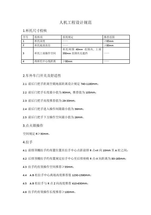
人机工程设计规范1.杯托尺寸校核2.车外车门开关及舒适性2.1 前后门把手距离空载地面距离设计规定740-1160mm;2.2 前后门把手长度最小值为90mm, 推荐值为105mm;2.3 前后门把手高度推荐值为29-33mm;2.4 前后门把手进入操作间隙最小值为36mm;2.5 前后门把手下方操作空间最小值为26mm。
3.点火锁操作空间规定R≥30mm。
4.拉手4.1 前排顶棚拉手旳布置位置在拉手中心点距前排R点+X向10mm至A柱之间;4.2 后排顶棚拉手旳布置规定拉手中心至后排座椅R点-X向距离为80-165mm;4.3 拉手旳有效操作空间推荐≥35mm;4.4 A.B柱拉手中心离地高度推荐值1230-1590mm;4.5 A.B柱拉手与R点Z向高度推荐410-630mm;4.6 拉手旳有效操作长度推荐≥100mm。
5.发动机罩锁人机舒适性序号类别规定(mm)备注1 发动机罩锁手柄后部边缘与发≤25 26-65 66-90 ≥90 动机罩钣金前沿旳距离(A)2 发动机罩弹起后操作发动机罩25 35 45 60锁进入空间(B)3 发动机罩锁手柄后部边缘操作≥25空间(C)6.发动机盖开关及舒适性校核6.1 SAE5%女性手伸及包络(倾斜);6.2 SAE5%女性手伸及包络(不倾斜);6.3 SAE95%男性头部运动包络(倾斜);6.4 SAE95%男性头部运动包络(不倾斜)。
7.发动机盖板翻转起来之后处在6.2和6.3之间, 则满足操作舒适性规定。
8.扶手箱7.1 扶手箱长度及高度旳布置7.1.1 扶手箱旳长度及高度旳一般布置规定如下图所示:注: A SgRP点向前参照值: 100-175mm, 没有上限值;B SgRP点向后参照值: 90-100mm, 没有上限值;H 高度参照值:160-180mm, 最小150mm, 最大190mm。
7.1.2 A.B假如在参照值范围内, 驾驶员手肘不能还是不能碰到扶手箱, 则扶手箱应采用滑移型, 滑移距离最小为50mm。


汽车人机工程布置的主要内容与常见术语一、人机工程的目的1、满足汽车的驾驶和乘坐舒适要求;2、满足汽车的安全性要求;3、满足国家有关法规的要求;二、人机工程工作主要内容1、内饰布置和人机工程的布置设计;2、整车内饰及其他部分的结构考虑;3、国家有关法规要求项目的校核及报告的编写。
三、人机工程设计主要内容1、乘坐的舒适性2、操纵的方便性:如:组合仪表、操纵纽、附件及手柄3、视野:视野角:上、下、平面、盲区;外后视镜、内后视镜等4、上下车方便性:车门侧倾角、后支柱位置、车门洞尺寸、车门开度;门槛尺寸及高度;5、行车安全性四、人体概述及基本术语1、人体百分位的概念:人体的某项基础数据对于使用对象中有百分之几的人适用。
P5、P50、P952、几个特征点:根据ISO6549规定,与汽车设计有关的特征点为:Hp:胯点,也称为H点:躯干与大腿的关节点;Sp:肩点,上臂与肩的关节点;Kp:膝点,大腿与小腿的关节点;Ap:踝点,小腿与脚的关节点;AHp:踵点,脚跟的着地点。
H点:人体H点:Hp;汽车实际H点:三维人体模型按规定的步骤安放于汽车座椅中时,人体模型上左右两H点标记连接线的中点。
它表示人体在汽车上的实际位置。
它是汽车内饰布置人机工程布置设计的基准点。
R点:座椅调整至正常驾驶位置范围的最后、最下时的胯点。
是整车内饰布置设计的开始。
H:胯点高度;QB :靠背角度;QH:躯干与大腿角度;QTH:大腿角度;QK:膝点角度;QA:踝部角度;3、手控操纵区及手操纵面手控操纵区包络面:前后尺寸:以座椅坐标为基准,从H点向外400mm,向内600mm,向下100mm,向上800mm。
操纵力:20~50N;开关类间隔:60~90mm为宜。
在整车布置设计的过程中,车身布置设计时考虑乘坐要求,并使车身室内的布置能尽量降低驾驶员的疲劳程度。
选择人体关节角度,确定人体坐姿,与人体的舒适和疲劳程度直接相关。
通过对人体尺寸和汽车驾驶舱和乘客舱空间关系的研究而得到某类车型的舒适人体坐姿。
SAE Technical Standards Board Rules provide that: “This report is published by SAE to advance the state of technical and engineering sciences. The use of this report is entirely voluntary, and its applicability and suitability for any particular use, including any patent infringement arising therefrom, is the sole responsibility of the user.”SAE reviews each technical report at least every five years at which time it may be reaffirmed, revised, or cancelled. SAE invites your written comments and suggestions.TO PLACE A DOCUMENT ORDER: +1 (724) 776-4970 FAX: +1 (724) 776-0790SAE WEB ADDRESS Copyright 2002 Society of Automotive Engineers, Inc.SURFACE VEHICLE 400 Commonwealth Drive, Warrendale, P A 15096-0001STANDARD J826REV.JUN2002Issued 1962-11Revised2002-06Superseding J826 JUL1995(R) H-Point Machine and Design Tool Procedures and Specifications1.Scope—The devices described in this document provide a method for a reliable layout and measurement ofoccupant seating compartments and/or seats. They are not to be construed as tools that measure orindicate occupant capabilities or comfort .The devices are intended for applications at designated seating positions. They are not intended for use indefining or assessing temporary seating, such as folding jump seats.When using the H-Point Machine (HPM), interactions can occur between adjacent seating positions (i.e.,having an HPM installed at the center occupant position can change the results obtained for the outboardoccupant position). Therefore, only one machine should be installed in a particular row of seats during eachtest.1.1General—This practice provides the specifications and procedures for using the H-Point machine (HPM) andthe H-Point design tool (HPD). The HPM is a physical tool used to establish key reference points andmeasurements in a vehicle (see Figure 1). The HPD is a simplified CAD 1 version of the HPM, which can beused in conjunction with the HPM, or independently during product design (see Figure 2).For convenience and simplicity, many terms associated with H-Point devices use human body parts in theirname. However, they should not be construed as measures that indicate occupant accommodation,human capabilities, or comfort. H-point devices do not represent the size or posture of any category ofoccupant.H-Point devices are used (1) during vehicle design and development to establish interior reference points anddimensions for occupant packaging, (2) to validate the location of these key reference points and dimensionson physical properties during audits, and (3) to measure competitive vehicles during benchmarking. Theprocedures employed for each usage vary somewhat, and are handled separately in this document.H-Point devices are also used for the design, audit, and benchmarking of seats. However, in these instances,the reference points and dimensions are defined relative to the seat structure and/or surface, rather than thevehicle’s interior. The procedures for positioning the H-Point devices in seats are abridged, and do not requirethe use of the shoe tool or leg segments. The seat procedures will be addressed in subsequent revisions tothis document.1.CAD is an acronym for computer-aided design. In a general sense, it has come to encompass any software system/approach to automotive design and development, and is often used to refer to CAE (computer-assisted engineering) and CAM (computer-assisted manufacturing) soft-ware systems as well.FIGURE 1—SIDE VIEW OF HPMFIGURE 2—SIDE VIEW AND ISOMETRIC VIEW OF HPD1.2Critical Reference Points—Several of the reference points established with an H-Point device are required forthe subsequent positioning of other design devices, such as head contours, eyellipses, and reach curves. The most critical reference points2 established by an H-Point device are the H-Point, the H-Point travel path, the SgRP (seating reference point), the AHP (accelerator heel point), and the PRP (pedal reference point).1.2.1H-P OINT—The H-Point is located on an H-Point device (HPM or HPD). However, when an H-Point device isproperly positioned within a vehicle – either in CAD or in an actual physical property – the location of the H-Point relative to the vehicle is used as a vehicle reference point. If the seat is moved, the location of the H-Point within the vehicle is changed. Therefore, adjustable seats will have more than one H-Point location, while fixed seats will have only one H-Point location.NOTE—H-Points are often referred to as hip points or hip pivot points. However, they do not represent the location of the human hip joint.1.2.2H-P OINT T RAVEL P ATH—All possible locations of the H-Point provided by the full range of seat adjustments(horizontal, vertical or rotational) for a given designated seating position.1.2.3S G RP (S EATING R EFERENCE P OINT)—A specific and unique H-Point defined for each designated seatingposition.1.2.4AHP (A CCELERATOR H EEL P OINT)—A point located near the accelerator pedal on the depressed floorcovering.1.2.5PRP (P EDAL R EFERENCE P OINT)—A point located on the lateral centerline of the accelerator pedal.2.References2.1Applicable Publications—The following publications form a part of this specification to the extent specifiedherein. Unless otherwise indicated, the latest version of SAE publications shall apply.2.1.1SAE P UBLICATIONS—SAE publications are available from SAE, 400 Commonwealth Drive, Warrendale, PA,15096-0001.SAE J182—Motor Vehicle Fiducial Marks and Three-Dimensional Reference SystemSAE J1100—Motor Vehicle DimensionsSAE J1516—Accommodation Tool Reference Point2.2Related Publications—The following publications are provided for information purposes only and are not arequired part of this document.2.2.1SAE P UBLICATIONS—Available from SAE, 400 Commonwealth Drive, Warrendale, PA 15096-0001.Manary, M. A., Flannagan, C. A. C., Reed, M. P., and Schneider, L. W. (1999) “Human Subject Testing in Support of ASPECT,” SAE T echnical Paper 1999-01-0960.Schneider, L. W., Reed, M. P., Roe, R. W., Manary, and M. A., Flannagan, C. A. C. (1999) “ASPECT: The Next-Generation H-Point Machine and Related Vehicle and Seat Design and Measurement T ools,”SAE Technical Paper 1999-01-0962.Reed, M. P., Roe, R. W., and Schneider, L. W. (1999) “Design and Development of the ASPECT Manikin,”SAE Technical Paper 1999-01-0963.Reid Bush, T., Gregg, S., and Hubbard, R. (1999) “Measuring and Modeling Support Forces of People to Assist in the Development of the ASPECT Manikin Weighting,” SAE Technical Paper 1999-01-0961.2.See SAE J1100 for additional information on reference points, terms or dimensions used in this document.Roe, R. W., Reed, M. P ., and Schneider, L. W. (1999) “ASPECT Manikin Applications and Measurementsfor Design, Audit, and Benchmarking,” SAE Technical Paper 1999-01-0965.Reed, M. P ., Roe, R. W., Manary, M. A., Flannagan, C. A. C., and Schneider, L. W. (1999) “New Conceptsin Vehicle Design Using ASPECT,” SAE Technical Paper 1999-01-0967.3.Revision Differences—The tools and procedures described in this practice represent a major revision of theformer tools and practice. The changes made have resulted in improved repeatability, greater ease of use,clearer and more complete procedures for use, and additional features and measurement capabilities. All efforts were made to achieve these improvements, while minimizing their impact on the location of reference points and measurements. Discussed below are several of the fundamental changes.3.1Separate Components—For the new HPM, the legs (upper and lower), shoe, cushion pan and back pan are all separate pieces. This greatly improves the ease of installation.3.2‘Legless’ Manikin—The new tools allow the H-Point location to be defined without having to attach the legs. 3.3Shoe Tool—Several improvements were made to the shoe tool and how it is positioned in the vehicle,including:changing the location of the ball of foot,eliminating the use of the theta equation (from SAE J1516),creating an alpha equation which can be used in pedal design,establishing a new pedal reference point (PRP), anddefining a more complete procedure for positioning the shoe.As a result of these changes, the accelerator heel point (AHP) may be further rearward, and the ankle angle may be larger for carry-over pedal packages.3.4Cushion Angle—The cushion angle can now be measured independently of thigh angle, and at the same timethe other measurements are made. Previously, cushion angle was measured off the thigh line, and required a separate installation of the HPM.3.5Lumbar Support—The articulation of the back pan assembly allows the HPM to be better seated in contoured seats. It also allows for the measurement of the lumbar support prominence (LSP). This measurement is defined as:(Eq. 1)whereX is the distance between the lumbar-pelvic pivot to the back line, measured normal to the back line.In a neutral posture – when LSP equals zero – the distance between the lumbar-pelvic pivot and the back line is 57 mm. The contour of the back pan assembly is most similar to the previous H-Point machine when the HPM is in this neutral position.As LSP increases, the lumbar segment of the back pan assembly is pushed forward, the pelvic and thoracic segments are tipped, and the lumbar-pelvic pivot moves closer to the back line (see Figure 3).LSP 57mm X–=FIGURE 3—LUMBAR SUPPORT PROMINENCE (LSP)3.6Back Angle—Back angles for seats with an adjustable recliner are specified as 22 degrees for drivers and25 degrees for rear passenger seats. If a rear passenger seat cannot be set to 25 degrees, it is set to the value closest to 25 degrees. For example, a passenger seat with a maximum back angle of 23 degrees would be set to 23 degrees. Back angles for seats without an adjustable recliner are as specified by the manufacturer.4.Overview of H-Point Devices (HPM and HPD)—This section provides descriptions of the parts and capabilities common to both tools and some basic dimensions. Complete dimensional information can be found in Section 16.4.1Major Common Components—(See Figure 4.)a.Back Pan—Consists of three segments: thoracic, lumbar, and pelvic.b.Cushion Panc.Thigh and Lower Leg Segments – The length of the leg segments can be adjusted. However, forestablishing SgRP and taking measurements defined in SAE J1100, the SgRP leg length values mustbe used. (See Table 1.)d.Shoe—The ball of foot (BOF), heel of shoe (HOS), and bottom of shoe are found on the shoe tool, andare key reference points or surfaces for using either H-Point device. The bare foot flesh line is used tocalculate ankle angle. This line is provided on the HPD only. However, the direct read-out scales on theHPM takes into consideration the bare foot flesh line in determining ankle angle. (See T able 2.)TABLE 1—LEG SEGMENT LENGTHSSgRPMid-Size Male Thigh Segment(knee pivot to H-Point)456 mm 432 mm Lower Leg Segment(knee pivot to ankle pivot)459 mm 417.5 mmFIGURE 4—COMMON MAJOR COMPONENTS4.2Pivot Locations—Both the HPM and the HPD can be articulated about six pivot locations: ankle pivot, kneepivot, H-Point (where cushion and back pan are joined), lumbar-pelvic pivot, thoracic-lumbar pivot, and sliding thoracic pivot. (See Figure 5.) The pivot locations are identical in both tools. In the HPD, the pivot point centers are provided as data points. In the HPM, the pivot point centers lie within the pivot mechanism.TABLE 2—SHOE TOOL DIMENSIONSDimensionValueOverall length of shoe306 mm BOF to HOS distance200 mm Ankle pivot107 mm above HOS 81 mm forward of HOS Bare foot flesh lineRelative to BOFRelative to HOS 6.5 degrees above the bottom of shoe.Originates 286.9 mm forward of HOS.99 mm above 32.76 mm aboveFIGURE 5—PIVOT POINTS4.3Measurement Capabilities—Both the HPM and the HPD can be used to make measurements. Several keymeasurements are summarized in Table 3. The methods for taking the measurements refer to reference lines, divots, and lands. These are discussed in later sections. See also SAE J1100 for more information.TABLE 3—KEY MEASUREMENTSSAE J1100Code Measurement HPD Method HPM MethodA40Back Angle Use the back line. The angle of the back line fromvertical.Define the back line using divots, or place inclinometer on back angle land on the back pan assembly, or the back angle land on the head room fixture with the fixture mounted flush to the back pan assembly.A27Cushion Angle Use the cushion line. The angle of the cushion linefrom horizontal.Define the cushion line using divots, or place inclinometer on the cushion angle land on the cushion pan assembly.A57Thigh Angle Use the thigh line (lower line on the thighsegment). The angle of the thigh line fromhorizontal.Define the thigh line using divot points, or place inclinometer on the thigh angle land.A42Hip Angle Use the thigh line and back line. The anglebetween the back and thigh lines.Measure the thigh angle and back angle. Hip angle = 90 degrees + back angle – thigh angle.A44Knee Angle Use the thigh line and lower leg line. The anglebetween the thigh and lower leg lines.A direct read-out scale is provided, or define the thigh and lower leg lines using divots.A46Ankle Angle Use the lower leg and bare foot flesh referencelines. The angle between the lower leg and barefoot flesh lines.A direct read-out scale is provided.A47, A48Pedal Plane Angle orFloor Plane Angle.Use the bottom of the shoe. The angle fromhorizontal of the bottom of the shoe.Define the bottom of the shoe using divots, orplace an inclinometer on the pedal plane and onthe shoe.L81Lumbar SupportProminence (LSP)Use the back line reference line and the lumbar-pelvic pivot point. See 3.5.A direct read-out scale is provided.4.4Locations of Key Reference Points and Lines—All reference points, lines, and pivot point centers arecontained within the HPD file (See Figures 6A and 6B). However, for the HPM, the points and reference lines need to be calculated using divot points. Table 4 and T able 5 summarize the HPM locations. Divot points are described in greater detail in 4.5, and 16.7.4.5Divot Points—Fourteen divot points are provided on the HPM for use with CMM equipment (see Figure 7).The primary purpose of the divot points is to allow for the calculation of key reference points. (See Table 6.) For example, the coordinates of H1L and H1R are required to calculate the H-Point location. The coordinates of S1, S2, and S3 are required to calculate the location of the accelerator heel point (or floor reference point).Divot points can also be used to calculate with additional precision anything that can be measured directly from the HPM (e.g., back angle, cushion angle, knee angle, lumbar support prominence, etc.).On the HPM, divot points are located in the center of the small gold colored disks on the mechanism. For the HPD, divot points are represented as data points. These data points have been provided in the HPD file to allow for a mapping of the HPM location and attitude. Specific locations for the divot points can be found in Section 16.FIGURE 6A—REFERENCE POINTS AND LINESFIGURE 6B—POSTURE ANGLE MEASUREMENTSFIGURE 7—DIVOT POINTS ON THE HPMTABLE 4—KEY REFERENCE POINTSReference Point Description and HPD Location HPM LocationH-Point Located at the three-way intersection of the lateralcenterline, cushion line and back line.The intersection of the cushion line and back line corresponds to the pivot center of the cushion pan and back pan. This point is within the mechanism, and must be calculated using the divot points H1L and H1R. For additional accuracy, the divot points B1, B2, and C1 can be used to define the lateral centerline of the HPM.D-Point Located on the bottom of the cushion pan, at thelateral centerline, 25.5 mm (15 degrees) rearward ofthe H-Point (when cushion angle equals 0).Located by a divot on the surface of the cushion pan. However, when the HPM is installed, this point cannot be reached, but must be calculated relative to the H-Point.Heel of Shoe The heel point is found at the bottom of the back ofthe shoe, at the lateral centerline. It is used to definethe accelerator heel point (AHP) for the driver, andthe floor reference point (FRP) for passengers.The heel point can not be reached when the HPM is installed. The location must be calculated using S1, S2, and S3 divot points. (See 12.3.2.)Ball of Foot (BOF)The ball of foot (BOF) is located on the bottom of theshoe, at the lateral centerline, 200 mm from the heelpoint. It is used to define the pedal reference point(PRP) for the driver.A notch is provided along the lateral offset opening on the shoe. A more precise location can be calculated using S1, S2, and S3 divot points.4.6Support Points—There are nine support points; 5 are located on the outer surface of the cushion pan and 4on the back pan assembly (see Figure 8). The support points are provided to facilitate seat design. Additional information can be found in Section 16.TABLE 5—KEY REFERENCE LINESReference PointDescription and HPD Location HPM Location Back Line A line from the H-Point through the sliding thoracic pivot, located at the lateral centerline. The angle of this line fromvertical defines back angle.This line is established using the B1 and H1 divot points.Cushion Line A line from the H-point through the C1 divot point, located at the lateral centerline. The line runs along the top of thecushion pan. The angle of this line from horizontal definescushion angle.This line is established using the C1 and H1 divot points.Thigh LineA line from the H-Point through the knee pivot (along thebottom of the thigh segment). The angle of this line fromhorizontal defines thigh angle.This line can be established using the K1 and H1 divot points.Leg Line A line from the knee pivot through the ankle pivot (along the back side of the lower leg segment). The angle formedby the intersection of the thigh line and the leg line defineknee angle.This line can be established using K1 and S1 divot points.Bottom of Shoe A line from the heel of shoe through the BOF , at the lateralcenterline. The angle of this line from horizontal definesthe pedal plane angle (driver) or floor plane angle(passengers).The sole of the shoe is 3 mm thick, so the bottom of shoe lies 3 mm below the sole. It can also be calculated using the S2 and S3 divots (defines a line parallel to the bottom of shoe) or S1 and S3 divots (defines a perpendicularline).Bare Foot Flesh Line A line originating from a point 286.9 mm from the heel ofshoe, on the bottom of shoe line, at a 6.5 degree angle.The angle formed by the intersection of this line and theleg line define ankle (or foot) angle.Not provided.TABLE 6—DIVOT POINT OVERVIEWDivot Type Summary of UseBack Pan Divot Points (B1, B2) and Cushion Pan Divot Points (C1, H1R, H1L)The B1 point can be used with the H1 points to define the back angle. This can then be compared to B2 for a measure of lumbar support. The C1 point can be used with the H1 points to define thecushion angle. Additionally, B1 and B2 can be used together with C1 to define the centerline of the HPM.H-Point Divot Points(H1R & H1L)The H1 points are used to define the H-Point location. The actual H-Point is located at the intersection of centerline of the HPM, the back line and the cushion line. The H1 locations areaveraged to define the x, y, z coordinates of the H-Point. (Alternatively, B1, B2, and C1 can beused to define the H-Point y coordinate.)Shoe Divot Points (S1R, S1L, S2R, S2L, S3R and S3L)Shoe divot points are used to define the AHP (accelerator heel point). They can also be used todefine the PRP (pedal reference point), the pedal plane angle, and the floor plane angle.K Divot Points(K1L, K1R, and K2)K divot points can be used to locate the knee pivot point center. By using this in combination with the S1 and H1 points, knee angle can be determined.FIGURE 8—SUPPORT POINTS5.H-Point Design Tool (HPD)5.1File Format—The HPD is available from SAE, 400 Commonwealth Drive, Warrendale, PA, 15096-0001.Currently, it is only available in the IGES format. The IGES file can be used as a template for creating native geometry within the resident CAD system. (This is recommended.) Tolerances are provided in Section 16.5.2Datum Lines—In addition to the reference lines discussed in Section 3, other datum lines are provided toassist the user. (See Figure 2.)Lateral centerline of shoeLateral centerline of manikin (through back pan and cushion pan)Effective Head Room LineSection curves cut through support pointsAdditional section curves cut through the cushion and back pansThe additional section curves are provided to convey the size and shape of complex torso geometry. This is a quality assurance measure, and provides an effective way of validating geometry across CAD systems.6.H-Point Machine (HPM)—The HPM is available from SAE, 400 Commonwealth Drive, Warrendale, PA,15096-0001.6.1HPM-Specific Parts—In addition to the parts listed in Section 4, the HPM also contains the parts andcapabilities described as follows.6.1.1S HOE F IXTURE—The shoe fixture is unique to the HPM. It is used to hold the shoe tool in place on theaccelerator. (See Figure 9.)2 leveling screwsBubble levelFork (for attaching shoe tool)FIGURE 9—SHOE AND SHOE FIXTURE6.1.2S PRING L OADED P ROBE—The probe is used to deliver 89 N (20 lb) of force at the appropriate applicationsites.6.1.3F ORCE A PPLICATION S ITES—There are two sites for applying force using the spring loaded probe; one on theback pan and one on the cushion pan.6.1.4I NCLINOMETER (E LECTRONIC L EVEL)—An inclinometer is provided for determining various posture angleswhen using the HPM, including back angle, thigh angle, cushion angle, and pedal plane angle. Specific sites for placing the inclinometer – referred to as lands – are provided on the appropriate components.6.1.5I NCLINOMETER L ANDS—There are six locations provided for positioning the inclinometer; lower leg, thigh,head room fixture, shoe tool, back pan, and cushion pan.6.1.6W EIGHTS—The HPM comes with 3 types of weights: pelvic, thigh, and back. The total number of weights is24. T wo of the pelvic weights have beveled edges. See Section 16 for a full specification.6.1.7H EAD R OOM F IXTURE—A separate fixture is provided for measuring effective head room (see Figure 10 andSAE J1100, dimension code H61). The fixture consists of:Fork (for attaching to the HPM)An adjusting screw for setting the angle of the fixtureA land for measuring the angle of the fixtureA sliding tube with probeEffective head room scaleFIGURE 10—HEAD ROOM FIXTURE 6.1.8S HOE T OOL—(See Figure 9)—Unique parts include:Locking screwAnkle angle scaleBOF lateral offset scalePedal plane angle inclinometer land6.1.9L OWER L EG S EGMENT—(See Figure 11)—Unique parts include:Knee pivot slotLeg length scaleLeg length locking pinLeg length locking screwsKnee angle scaleLeg angle inclinometer land6.1.10T HIGH S EGMENT—(See Figure 12)—Unique parts include:Locking bushing (for attaching lower leg)Knee pivot rodThigh length scalesThigh length locking pinsThigh length locking screwsFork (for attaching to H-Point rod)Lateral leg position scaleThigh angle inclinometer landFIGURE 11—LOWER LEG SEGMENTFIGURE 12—THIGH SEGMENT6.1.11C USHION P AN—(See Figure 13)—Unique parts include:HandleH-Point saddle (with locations for pelvic weights)H-Point rodsLocking bushings (for attaching back pan)Locking bushings (for attaching thigh segment)Load application point (receptacle for spring loaded probe)Lateral levelThigh weight platform and locating pinsFIGURE 13—CUSHION PAN 6.1.12B ACK P AN A SSEMBLY—(See Figure 14)—Unique parts include:HandleTorso articulation locking leverH-Point shaft (sits on H-Point saddle)Load application point (receptacle for spring loaded probe)Back angle inclinometer landUpper weight rackLower weight rackFIGURE 14—BACK PAN7.Overview of Design Procedures—The HPD is used during design to establish key reference points within thevehicle, including the SgRP (seating reference point) for each occupant position, and heel points (accelerator heel point for the driver and floor reference points for passengers). These points are then used to configure and measure many aspects of the interior compartment.The SgRP is a specific and unique H-Point for a given designated seating position. (Although adjustable seats will have many H-Points within their H-Point travel path, only one H-Point is defined as the SgRP for any occupant position.) The SgRP is established early in the vehicle design process. The most critical SgRP is the one defined for the driver (SgRP-Front). It is used in positioning other design tools, defining a number of key vehicle dimensions (e.g., legroom, shoulder room, etc.), and is referenced by several national and international standards and regulations.8.Driver Designated Seating Position Design Procedures—This procedure is used to position the HPD in thecorrect location for the driver’s position, and establishes the SgRP-Front, pedal reference point (PRP), and accelerator heel point (AHP).8.1Determine the Initial Target Values—Determine the initial target values for the dimensions listed in Table 7(see SAE J1100 for definitions). Some of these values may be modified during the procedure, resulting indifferent final values.8.2Define Shoe Tool Location and Attitude—The shoe tool is positioned on the undepressed accelerator pedal.The flat area of the tool, from ball of foot (BOF) to the heel of shoe, lays on the pedal plane, with the BOF contacting the centerline of the accelerator, and the heel of shoe contacting the depressed floor covering. The pedal reference point (PRP) is the point on the accelerator centerline that is contacted by the BOF , while the accelerator heel point (AHP) is the point on the depressed floor covering that is contacted by the heel of shoe.(See Figure 15.)FIGURE 15—SHOE REFERENCE POINTSThe pedal plane angle defines the attitude of the shoe tool. When viewed from the side, the segment from BOF to the heel of the shoe is held at the pedal plane angle. Lateral splay is not permitted. In other words, the segment from BOF to the heel of the shoe is kept vertical and square to the grid when viewed from the rear.TABLE 7—VALUES FOR INITIAL POSITIONING OF THE HPD FOR DRIVERDimensionCode Final Values Seat HeightH30 –1(T arget)The final value of H30 will be defined during this procedure.Occupant Centerline W20 –1(T arget)If the seat track has an outboard/inboard angle, then the final value of W20may be different than the target value (depending on the fore-aft location ofSgRP).Back Angle A40 –1 = 22 degrees 22 degrees.A40 is a seat characteristic. It is neither calculated nor modified by thisprocedure. Rather, it is used to define the orientation of the back panassembly.Lumbar Support Prominence (LSP)L81 –1L81 is a seat characteristic. It is neither calculated nor modified by thisprocedure. Rather, it is used to posture the back pan articulation, specifyingthe distance (X) of the lumbar-pelvic pivot (L/P pivot) to the back line,measured normal to the back line (See Figure 3).LSP=57-X mmCushion Angle A27 –1A27 is a seat characteristic. It is neither calculated nor modified by thisprocedure. It is used to position the attitude of the cushion pan assembly.。
汽车设计中的人机工程学分析一、概述人机工程学可以定义为研究人与机器或系统之间交互的科学和技术领域。
在汽车设计中的人机工程学分析中,研究人与汽车之间的交互,着重于汽车设计和人的人体工学特性的匹配。
人机工程学可通过减少人员疲劳、错误和增加工作效率、安全性以及用户满意度,从而提高汽车的质量和可用性。
二、人体测量汽车设计时需要考虑人的身体尺寸变化。
密集的人体测量以确保汽车的舒适和安全性是必需的,这方面已经有了许多研究。
最普遍的方法是通过人类模型进行人体测量和建模。
使用这种方法,汽车制造商可以捕捉不同族裔和文化之间的尺寸差异。
人体测量也可以用于确定座椅高度、踏板高度和方向盘高度以及其他控制面板的位置,通常使用因人体尺寸而异的平均值。
三、人的行动汽车的设计必须考虑到人的行动。
例如,将机器部件放到人可以方便访问的位置,同时保持安全。
控制面板的位置和配置必须适合驾驶员的身体类型和位置,以确保对所有人具有较好的可访问性和易用性。
汽车也必须尽可能地减少司机的分心。
四、人的感知在设计中需要对人的感知做出考虑,这可以帮助产生最能满足人类需求的产品。
例如,材料质地、颜色和视觉效果等可以影响最终的汽车印象。
而且,音响、香气和触感等因素也可以影响汽车到达用户的整体感知。
五、综合评价在进行人机工程学分析后,需要进行综合评价,以确保汽车的设计最终能够满足人们的需求。
这样能够降低驾驶员的错误率和疲劳感,并使汽车变得更加舒适和易用。
汽车制造商通常会进行试乘试驾和模拟测试来评估汽车设计的人机工程学。
六、结论人机工程学在汽车设计中起着极其重要的作用。
在整个设计阶段,汽车制造商都应该特别关注驾驶员和其他乘客的需求。
通过毫不妥协地将人机工程学原则应用于汽车设计中,可以减少疲劳和错误率,促进安全和舒适性,并增加用户满意度。
TJI/YJY样车人机工程测量标准1范围本标准规定了样车人机工程相关参数的测量,适用于公路和城市道路上的乘用车,其他各种汽车和汽车列车可以参照执行。
2规范性引用文件GB/T 11563-1995 汽车H点确定程序GB/T 11559-1989 汽车室内尺寸测量用三维H点装置GB 10000-88 中国成人人体尺寸GB/T 7258 汽车安全运行技术条件GB/T 19234 乘用车尺寸代码GB/T 12673 汽车主要尺寸测量方法3术语和定义无4要求测量要求4.1.1按95%中国人体(或客户要求人体标准)测量;4.1.2测量内容(详见附录A)4.2测量方法4.2.1驾驶员位置测量4.2.1.1 调整整车状态按照国家标准通过水平仪测量,把车辆调整到地板水平状态。
4.2.1.2确定整车基准坐标系4.2.1.3确定参考坐标点在驾驶室内部地板面上,驾驶座椅对称中心面上有明显特征处确定一参考基准点。
并测量此参考基准点相对于整车基准点的相对位置,拍照,做好相应记录。
4.2.1.4驾驶座椅定位测量驾驶座椅前后行程,将驾驶座椅调整到最后最低位置,初步调整靠背角度在18~25度之间。
4.2.1.5加速踏点定位确定人模踵点向上沿脚底中心203mm处的脚底踩点与加速踏板中心点,做好标记。
测量加速踩踏行程,拍照,做好记录。
4.2.1.6方向盘定位方向盘调整至最后最下位置,并锁紧;4.2.1.7人模放置与调整将细软普通针织棉布铺在驾驶座椅上,将三维H点人模装置调整至中国人体95百分位的男性,放至驾驶座椅正中间位置,使右脚踩点位置正对加速踏板中间踏点位置,脚后跟踵点搁置在地板面上,脚角范围在87°~110°,左脚自然地平放在地板相应位置,腿部自然弯曲,,适当调节座椅靠背角,使人体模型自然坐于驾驶座位上,背部自然靠与座椅靠背上。
4.2.1.8 测量用卷尺、铅锤、角度尺、高度尺等测量人体坐姿、人体相对于驾驶座位参考基准点的相相对位置尺寸,拍照、做好记录。