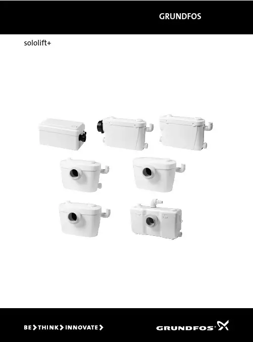
格兰富污水提升器 sololift+databooklet
- 格式:pdf
- 大小:7.10 MB
- 文档页数:20
中文 (C N )167中文 (CN) 安装和使用说明书目录页1. 概述本手册介绍了格兰富CMV泵的安装和操作。
2. 本文献中所用符号3. 运输和吊装格兰富CMV水泵的出厂包装,专为可用叉车起吊的货车或相同的运输车辆而设计。
4. 应用CMV 泵为立式多级离心泵,用来泵送清洁、粘度小、无爆炸性液体,且不得含有对水泵造成机械或者化学损伤的固体颗粒物质或者纤维。
1.概述1672.本文献中所用符号1673.运输和吊装1674.应用1675.标识1685.1铭牌1686.机械安装1686.1泵的安装1686.2管路连接1687.电气安装1697.1电源电缆1697.2电机保护1697.3电气连接1697.4变频器操作1698.启动1708.1加液1708.2检查旋转的方向1709.轴封磨合17110.维护和服务17110.1霜冻防护17110.2清洁处理17111.维护17112.技术数据17112.1防护等级17112.2声压级17112.3启动和停机频率17112.4环境温度17112.5储存及运输温度17112.6系统最大压力和液体允许温度17212.7最小入口压力17212.8最大入口压力17213.故障查找17314.该产品的其它文献17414.1服务文献17415.回收处理174警告装机前,先仔细阅读本安装操作手册。
安装和运行必须遵守当地规章制度并符合公认的良好操作习惯。
警告使用该产品时要求用户事先掌握有关的产品知识和产品经验。
任何在体力、感觉力或脑力方面存有缺陷的人员,除非是在负责他们安全的人员的监督下或是已从负责安全监督的人员处接受了有关本产品使用的指导,否则均不应该使用本产品。
不允许儿童使用本产品或将本产品作为玩具。
警告不执行这些安全须知可能会引起人身伤害。
小心不执行这些安全须知可能会导致故障发生或设备损坏。
注意可以使工作简化和保证安全的注意事项或须知。
注意为了确保运输安全,推荐使用合适的起吊工具来运输泵。
GRUNDFOS说明书SMG, SFGMixers and flowmakers安装和使用说明书中文 (CN)2中文 (CN) 安装和使用说明书中文版本。
这些安装和操作说明介绍了格兰富SMG、SFG搅拌器和推流器。
章节1-6介绍了以安全的方式拆包、安装并启动本产品所需的信息。
章节7-11介绍了有关产品的重要信息,以及有关服务、故障查找和产品处置的信息。
目录页1. 概述本手册包括有关格兰富SMG型潜水搅拌器和SFG型潜水推流器的安装、操作及维护的说明。
潜水搅拌器和潜水推流器均为各种搅拌应用而设计,如搅拌低粘度和中等粘滞度(≤500 mPas)的均质液和悬浮液。
1.1 本文献中所用符号2. 安全2.1 安全概述1.概述21.1本文献中所用符号22.安全22.1安全概述23.运输、交付和储存33.1运输33.2运输33.3存放34.安装34.1有用信息34.2布置44.3安装一台搅拌器54.4安装一台推流器75.电气连接125.1电机保护125.2齿轮箱/机封室保护135.3过载继电器135.4启动方式145.5接线图145.6转动方向145.7电化学腐蚀的防护156.启动157.产品介绍167.1产品说明167.2应用167.3标识178.维护188.1污染的潜水搅拌器或潜水推流器188.2服务一览表198.3机油208.4更换机油209.故障查找2110.技术数据2210.1通用技术参数2210.2电机2210.3齿轮箱2210.4轴封2210.5桨叶2210.6声压级2211.回收处理22警告装机前,先仔细阅读本安装操作手册。
安装和运行必须遵守当地规章制度并符合公认的良好操作习惯。
注意AMD.07.18.1410 潜水搅拌器有单独的安装与操作指导。
参见 网页,出版号 96526302。
关于标准和Ex版本AMD、Ex版本AMG和AFG的信息,请参见上编号为96498078的文件。
警告不执行这些安全须知可能会引起人身伤害。

格兰富污水提升器好评评语
一.质量好
供应成套污水提升设备的质量相对值得信赖。
在排放大量污水时,不需要担心污水会从成套污水提升设备的管道中泄漏,因为成套污水提升设备的每一个部件都是精心设计的,所以零件之间没有缝隙,没有缝隙,污水就不会泄漏。
二、使用寿命长。
成套污水提升设备价格便宜,但使用寿命不短。
这一优点增强了成套污水提升设备的使用寿命,使人们不再需要定期更换成套污水提升设备,因为更换会产生不可避免的成本,这将影响客户公司的经济效益使用寿命也表明成套污水提升设备的质量非常牢固。
三.无异味
成套污水提升设备以低价出售,也可以向客户承诺其材料的严密性。
当污水通过成套污水提升设备时,可以降低异味。
由于成套污水提升设备是由特殊材料制成的,可以将奇怪的气味隔离在设备中,使人们在工作日不需要被沉重的气味包围。
在了解了上述三种成套污水提升设备的优点后,我们可以理解,成套污水提升设备的质量非常合格和可靠。
在生活污水处理过程中,成套污水提升设备不会泄漏或散发异味,导致人们无法正常工作,成
套污水提升设备因其使用寿命长而受到人们的喜爱和欢迎。
设备在使用过程中的使用感是人们会关注和关注的地方。
CR, CRN 高压GRUNDFOS DATA BOOKLET立式多级离心泵50 Hz目录产品数据性能范围介绍产品范围应用CRNE 1及3 HSCRN 5, 10, 15, 20 SF2 x CR 32, 45, 64, 902 x CRN 32, 45, 64, 902 x CRN 120, 1502 x CRN 120, 150型号说明代码高压泵轴封运行范围接线盒位置输送液体性能曲线适用原则选型和尺寸CR, CRN高压泵的选型性能曲线/技术数据CRNE 1-HS, 50/60 HZ CRNE 3-HS, 50/60 HZ CRN 3-SF , 50 HZCRN 5-SF, 50 HZCRN 10-SF, 50 HZCRN 15-SF, 50 HZCRN 20-SF, 50 HZCR 32, 50 HZCRN 32, 50 HZCR 45, 50 HZCRN 45, 50 HZCR 64, 50 HZCRN 64, 50 HZCR 90, 50 HZCRN 90, 50 HZCR 120,50 HZCRN 120,50 HZCR 150,50 HZCRN 150,50 HZ电气数据CR,CRN高压泵标准电机 , 50HZE电机,CRN HS , 50HZE电机,CRN SF , 50HZCR,CRN高压泵标准电机 , 60HZE电机,CRN HS , 60HZE电机,CRN SF , 60HZ附件管路连接用于CRN的对接法兰转接组件PJE连接器带接管连接管PJE连接器不带管CRNE-HS用压力传感器LiqTecWEBCAPS34556788991010111111111214161820222426283032343638404244464850525252535353545454555555565657性能范围T M 02 1689 4007介绍本样本针对C R,C R N泵的高压应用,两种方法获得高压:●单台泵,配内置变频器的高速电机-CRNE-HS 1&3●双泵串联,给水泵+高压泵-CRN-SF 3到20-CR,CRN 32到150依据泵的型号不同,高压泵共有两种结构形式:●CRNE-HS和CRN-SF与标准泵相比,流道腔反置●CR,CRN:标准泵或加装轴承法兰高压泵得到的高压力是由泵的特殊设计实现的。
GRUNDFOS 数据手册Medium UPM泵UPMM, UPML, UPMXL, UPMXXL, SOLAR PMLEU系列1 x 230 V, 50/60 Hz目录2Medium UPM?1.概述3Medium UPM泵 - EU系列. . . . . . . . . . . . . . . . . . . . . . . . . . . . . . . . . . . . . . . . . . . . . . . . . . . . . . . . . . . . . . . . . . . . . . . 3应用 . . . . . . . . . . . . . . . . . . . . . . . . . . . . . . . . . . . . . . . . . . . . . . . . . . . . . . . . . . . . . . . . . . . . . . . . . . . . . . . . . . . . . . . . 3安全指导. . . . . . . . . . . . . . . . . . . . . . . . . . . . . . . . . . . . . . . . . . . . . . . . . . . . . . . . . . . . . . . . . . . . . . . . . . . . . . . . . . . . . 52.特点与优点6特点 . . . . . . . . . . . . . . . . . . . . . . . . . . . . . . . . . . . . . . . . . . . . . . . . . . . . . . . . . . . . . . . . . . . . . . . . . . . . . . . . . . . . . . . . 6优点 . . . . . . . . . . . . . . . . . . . . . . . . . . . . . . . . . . . . . . . . . . . . . . . . . . . . . . . . . . . . . . . . . . . . . . . . . . . . . . . . . . . . . . . . 6 ERP,生态设计规范. . . . . . . . . . . . . . . . . . . . . . . . . . . . . . . . . . . . . . . . . . . . . . . . . . . . . . . . . . . . . . . . . . . . . . . . . . . . 6标识 . . . . . . . . . . . . . . . . . . . . . . . . . . . . . . . . . . . . . . . . . . . . . . . . . . . . . . . . . . . . . . . . . . . . . . . . . . . . . . . . . . . . . . . . 73.性能概览84.产品范围95.控制模式和信号10控制原理. . . . . . . . . . . . . . . . . . . . . . . . . . . . . . . . . . . . . . . . . . . . . . . . . . . . . . . . . . . . . . . . . . . . . . . . . . . . . . . . . . . . 106.控制模式、用户界面和设置13供暖系统中的泵控制. . . . . . . . . . . . . . . . . . . . . . . . . . . . . . . . . . . . . . . . . . . . . . . . . . . . . . . . . . . . . . . . . . . . . . . . . . . 13控制模式说明. . . . . . . . . . . . . . . . . . . . . . . . . . . . . . . . . . . . . . . . . . . . . . . . . . . . . . . . . . . . . . . . . . . . . . . . . . . . . . . . 13用户界面. . . . . . . . . . . . . . . . . . . . . . . . . . . . . . . . . . . . . . . . . . . . . . . . . . . . . . . . . . . . . . . . . . . . . . . . . . . . . . . . . . . . 18 7.技术描述19爆炸图 . . . . . . . . . . . . . . . . . . . . . . . . . . . . . . . . . . . . . . . . . . . . . . . . . . . . . . . . . . . . . . . . . . . . . . . . . . . . . . . . . . . . . 19剖面观 . . . . . . . . . . . . . . . . . . . . . . . . . . . . . . . . . . . . . . . . . . . . . . . . . . . . . . . . . . . . . . . . . . . . . . . . . . . . . . . . . . . . . 20材料规格. . . . . . . . . . . . . . . . . . . . . . . . . . . . . . . . . . . . . . . . . . . . . . . . . . . . . . . . . . . . . . . . . . . . . . . . . . . . . . . . . . . . 20部件说明. . . . . . . . . . . . . . . . . . . . . . . . . . . . . . . . . . . . . . . . . . . . . . . . . . . . . . . . . . . . . . . . . . . . . . . . . . . . . . . . . . . . 21 8.安装尺寸23泵送液体. . . . . . . . . . . . . . . . . . . . . . . . . . . . . . . . . . . . . . . . . . . . . . . . . . . . . . . . . . . . . . . . . . . . . . . . . . . . . . . . . . . . 23机械安装. . . . . . . . . . . . . . . . . . . . . . . . . . . . . . . . . . . . . . . . . . . . . . . . . . . . . . . . . . . . . . . . . . . . . . . . . . . . . . . . . . . . 24电气安装. . . . . . . . . . . . . . . . . . . . . . . . . . . . . . . . . . . . . . . . . . . . . . . . . . . . . . . . . . . . . . . . . . . . . . . . . . . . . . . . . . . . 26 9.启动3110.维修3211.产品处置3412.性能曲线35曲线条件. . . . . . . . . . . . . . . . . . . . . . . . . . . . . . . . . . . . . . . . . . . . . . . . . . . . . . . . . . . . . . . . . . . . . . . . . . . . . . . . . . . . 3513.数据表3614.附件4515.批准和认证46EC产品合格声明书 . . . . . . . . . . . . . . . . . . . . . . . . . . . . . . . . . . . . . . . . . . . . . . . . . . . . . . . . . . . . . . . . . . . . . . . . . . . 46 VDE证书 . . . . . . . . . . . . . . . . . . . . . . . . . . . . . . . . . . . . . . . . . . . . . . . . . . . . . . . . . . . . . . . . . . . . . . . . . . . . . . . . . . . 47对某些不能使用的化学物质,格兰富提供产品化学符合声明. . . . . . . . . . . . . . . . . . . . . . . . . . . . . . . . . . . . . . . . . . . . 47 REACH法规(EC 1907/2006). . . . . . . . . . . . . . . . . . . . . . . . . . . . . . . . . . . . . . . . . . . . . . . . . . . . . . . . . . . . . . . . . . 47有关REACH、RoHS和其他相关化学品法规以及格兰富产品化学品合规性计划的客户信息. . . . . . . . . . . . . . . . . . . . 47 WEEE指令2012/19/EU. . . . . . . . . . . . . . . . . . . . . . . . . . . . . . . . . . . . . . . . . . . . . . . . . . . . . . . . . . . . . . . . . . . . . . . . 48 16.缩写493不同的管路可以安装不同版本的Medium UPM循环泵。

中文 (CN)452中文 (CN) 安装和使用说明书中文版本。
目录页1. 一般警告2. 本文献中所用符号3. 概述本手册对配备功率为9至30 kW电机的格兰富SE/SL潜水式污水及废水泵的安装、操作及保养进行了说明。
本手册还对泵作了特别说明。
3.1 应用9-30 kW的SE/SL泵主要用于泵送市政及工业废水系统中含有长、短纤维和较大颗粒的未经处理的污水,以及干固体颗粒含量达3 %(流道叶轮)和5 %(涡轮叶轮)的污泥。
此类泵的泵送液体可以是地表水,含有长、短纤维材料的工业废水,含有厕卫废物的住宅废水以及市政抽水站或废水处理工厂入口抽水站中未经筛选处理的污水。
此外,此类泵也可用于泵送未经净化的水。
水泵具有多种安装方式,包括潜水式、干式、卧式以及立式安装。
最大颗粒尺寸: 75-160 mm,视泵的具体性能范围而定。
1.一般警告4522.本文献中所用符号4523.概述4523.1应用4523.2运行条件4533.3声压水平4533.4电机液体4534.交付和吊装4544.1运输与存放4544.2起吊点4545.标识4555.1铭牌4555.2型号说明4566.安全4577.安装4587.1安装类型4587.2在自动耦合装置上的潜水式安装4597.3干式安装4597.4潜水式临时安装4607.5水泵控制器4608.电气连接4608.1传感器4618.2变频器操作4628.3电缆数据4629.启动46210.保养和维修46310.1检查并更换电机液体46310.2检查并调整叶轮间隙46410.3受污染的泵46511.故障查找46612.回收处理466警告装机前,先仔细阅读本安装操作手册。
安装和运行必须遵守当地规章制度并符合公认的良好操作习惯。
警告不执行这些安全须知可能会引起人身伤害。
警告如果不遵守这些操作指导会有触电危险并造成严重的人身伤害或死亡后果。
警告该产品的表面十分灼热可以引起烫伤或其它人身伤害。
二、格兰富Multilift MSS 产品组成和性能描述应用场合:Multilift MSS 用于收集别墅内低于下水道液位与远离市政排污管网的污水管和厕所排放的废污水,并将其提升和泵送至城市排污系统中。
独户住宅住宅地下室有桑拿浴、淋浴、地窖、杂物间等附加功能的扩建地下室空间非常有限的安装场合运行原理及产品特点:格兰富Multilift MSS 型污水提升站原产地欧洲,是专门设计用来收集那些低于下水道液面的管道和厕所中的污水,将其提升并输送至下水道管线中的产品。
该产品可提供水平或垂直入口及一个垂直出口连接方式,具有低噪音,气密、水密,防止气味泄漏的特点。
1、格兰富污水提升站通过集水箱收集低于下水道液位的废污水,箱体上有多种接口选择,垂直接口、水平接口,连接水泵、污水进水管、通风管。
特别在水箱背面和测面均有接口,可用于连接不同方向的污水管。
2、集水箱上装有液位传感器,液位传感器在一根管内结合了 4 个压力传感器。
压力传感器分别设置成不同的液位高度,到达其各自设定的液位时,每个压力传感器都会发给液位传感器一个信号。
信号通过传感器与控制器间的电缆传送给控制器,作出启停水泵的反应。
一旦集水箱内液位超过设置的高液位报警位置,传感器将传递信号给控制箱,发出鸣音警报。
相比使用浮球式的传感器,格兰富的压力传感器不与污水直接接触,避免污物沾染以后的水泵误动作,使控制更加准确,系统更安全。
3、格兰富密闭水箱,一次铸造,无任何接缝,避免任何异味和气体的泄漏。
钻开或锯开所需使用的接口,并用配套提供的卡箍和柔性进行管道连接,快捷、简便。
4、标准控制箱除常规水泵故障报警外,可提供高液位报警,并且有故障信号输出功能,便于物业进行中控,监测,确保全年运行。
5、整套设备均为欧洲全进口,在高档别墅、地铁等场合得到了广泛应用。
类似的项目案例如下:太阳湖别墅、上海栎庭别墅群、深圳纯水岸别墅、嘉柏货代公司活动区、苏州平门府别墅区、上海金桥瑞士花园、上海万源城等、格兰富Multilift MSS 产品基本情况说明表四、格兰富Multilift MSS 产品的Q-H 曲线以及外形尺寸图MSS.12.1.4 运行曲线安装尺寸图:五、格兰富Multilift MSS 产品的安装示意图安装示意图1、提升站必须处于平整地面上。
GRUNDFOS DATA BOOKLETGrundfos ALPHA1Circulator pumps50/60 HzTable of contents 2Grundfos ALPHA1 1.Product introduction3Type key3Performance range32.Applications4Pumped liquids4Control of heating systems5Advantages of pump control53.Construction7Stainless-steel versions N7Sectional drawing7Material specification7Motor and control box8Unique air vent system94.Installation and startup10Installation10Electrical data10Startup10Liquid temperature10System pressure10Inlet pressure10Setting the pump10Change of pump performance115.Guide to performance curves12Energy labelling12Curve conditions126.Performance curves and technical data13ALPHA1 15-40, 20-40 (N), 25-40 (N)(A), 32-4013ALPHA1 20-45 N14ALPHA1 15-50, 20-50 (N), 25-50 (N), 32-5015ALPHA1 15-60, 20-60 (N), 25-60 (N)(A), 32-60167.Accessories17Union and valve kits17Insulating kits17ALPHA plugs178.Product range18ALPHA1 (N), Germany19ALPHA1 (N), Austria and Switzerland19ALPHA1 (N), international209.Further product information21WebCAPS21WinCAPS22GO CAPS23Productintroduction3 Grundfos ALPHA11 1. Product introductionGrundfos ALPHA1 is a complete range of circulatorpumps with the following features:•integrated differential-pressure control enablingadjustment of pump performance to the actualsystem requirement•motor based on permanent-magnet/compact-rotortechnology.The pumps are energy-optimised and comply with therequirements of the EuP directive.Fig. 1EuP readyThe installation of one of these pumps will reducepower consumption considerably, reduce noise fromthermostatic valves and similar fittings and improve thecontrol of the system.The Grundfos ALPHA1 range offers a host ofadvantages:Energy savingsHigh-efficient permanent-magnet motors.FlexibilitySuitable for installation in existing systems.ComfortLow-noise operation.SafetyBuilt-in electrical and thermal protection of the pump.User friendlinessSimple setting and operation.Type key*Exception: UK version, size 15 = 1 1/2".Performance rangeFig. 2Performance rangeTM577451613Example ALPHA125 -40180Pump rangeNominal diameter (DN) of suction and discharge ports[mm](15 = 1"*, 20 = 1 1/4", 25 = 1 1/2", 32 = 2")Maximum head [dm][ ]: Cast-iron pump housingN: Stainless-steel pump housingA Pump housing with air separatorPort-to-port length [mm]TM4217284Fig. 3One-pipe heating systemFig. 4Two-pipe heating systemFig. 5Underfloor heating systemFig. 6Domestic hot-water recirculation systemPumped liquidsThe pump is suitable for clean, thin, non-aggressiveand non-explosive liquids, not containing solidparticles, fibres or mineral oil.The pump must not be used for the transfer offlammable liquids, such as diesel oil, petrol and similarliquids.TM398894575In a system with a Grundfos ALPHA1 pump, the pressure will be reduced by ΔH 2.Fig. 8Pump in proportional-pressure control modeIn a system with an uncontrolled pump, a pressure rise will often cause flow-generated noise in the thermostatic valves. This noise will be reduced considerably with the Grundfos ALPHA1.The pump has the following control modes •Proportional-pressure control •Constant-pressure control •Constant-curve control.T M 01 9120 5002HQΔH 112A 2A 1Q 1Q 2HQΔH 21A 2A 1A 3Q 1Q 26Fig. 10Three constant-pressure curves/settingsThe selection of the right constant-pressure setting depends on the characteristics of the heating system in question and the actual heat demand.Constant-curve controlAt constant-curve/constant-speed operation, the pump runs at a constant speed, independent of the actual flow demand in the system. The pump performance follows the selected performance curve, I, II or III.See fig. 11 where II has been selected. See Change of pump performance for further information.Fig. 11Three constant-curve/constant-speed settingsThe selection of the right constant-curve/constant-speed setting depends on the characteristics of the heating system in question and the number of taps likely to be opened at the same time.T M 05 3068 09127Stainless-steel versions NThe pump housing of the stainless-steel versions is painted in red colour. The stainless-steel versions can be identified by the N in the type key or by the silver ring around the display. See fig. 12.Fig. 12Stainless-steel version N*ALPHA1 20-45 N**ALPHA1 XX-40, XX-50, XX-60 NT M 06 1834 311411ShaftCeramics Rotor cladding Stainless steel 1.430130412Thrust bearing Carbon Thrust bearing retainer EPDM rubber 13Bearing plate Stainless steel 1.430130416ImpellerComposite, PP or PES 18Pump housing Cast ironEN-JL 1020A48-25Stainless steel 1.4301*304*1.4308**CF8**GasketsEPDM rubberFig. 14Push-button position ALPHA plug with cable relief and angled ALPHA plug with fixed cable328Fig. 17Pump housing with air-separating chamber910PN 10: Maximum 1.0 MPa (10 bar).Inlet pressureTo avoid cavitation noise and damage to the pump, thefollowing minimum pressures are required at the pumpsuction port.Setting the pumpUsing the push-button on the control box, theelectronically controlled pump can be set to thefollowing:•two constant-pressure curves•two proportional-pressure curves•three fixed-speed curves.Factory settingThe pump has been factory-set to proportional-pressure curve (PP2). See fig. 20.This setting is suitable for the majority of all single-family houses.Insulation class FRelative air humidity Maximum 95 %Ambient temperature0-40 °CTemperature class TF110 to CEN 335-2-51EMC (electromagneticcompatibility)EN 55014-1:2006 and EN 55014-2:1997Sound pressure level≤ 43 dB(A)Liquid temperature75 °C90 °C110 °C0.5 m head 2.8 m head10.8 m headPP1Lowest proportional-pressure curveThe duty point of the pump will move up or down on the lowest proportional-pressure curve, depending onthe heat demand in the system. See fig. 20.The head (pressure) is reduced at falling heat demand and increased at rising heat demand.PP2Highest proportional-pressure curveThe duty point of the pump will move up or down on the highest proportional-pressure curve, depending onthe heat demand in the system. See fig. 20.The head (pressure) is reduced at falling heat demand and increased at rising heat demand.CP1Lowest constant-pressure curveThe duty point of the pump will move out or in on the lowest constant-pressure curve, depending on theheat demand in the system. See fig. 20.The head (pressure) is kept constant, irrespective of the heat demand.CP2Highest constant-pressure curveThe duty point of the pump will move out or in on the highest constant-pressure curve, depending on theheat demand in the system. See fig. 20.The head (pressure) is kept constant, irrespective of the heat demand.III Speed III The pump runs at a constant speed and consequently on a constant curve.At speed III, the pump is set to run on the maximum curve under all operating conditions. See fig. 20. Quick venting of the pump can be obtained by setting the pump to speed III for a short period.II Speed II The pump runs at a constant speed and consequently on a constant curve.At speed II, the pump is set to run on the intermediate curve under all operating conditions. See fig. 20.I Speed I The pump runs at a constant speed and consequently on a constant curve.At speed I, the pump is set to run on the minimum curve under all operating conditions. See fig. 20.Fig. 21EEI limits and the current positioning of theALPHA1With an energy efficiency index (EEI) at the EuP 2015requirement level, you can achieve considerableenergy savings compared to a typical circulator pumpand thus a remarkably fast return on investment.Speed P1 [W]I1/1 [A]Min.50.05Max.220.19 The pump incorporates overload protection.Connections:See Insulating kits, page 14.System pressure:Max. 1.0 MPa (10 bar).Liquid temperature:2-110 °C (TF 110).TM579711713Pump type EEI <Dimensions [mm]Weights [kg]Ship. vol.[m3]L1B1B2B3B4H1H2H3G Net GrossALPHA1 15-400.231307878464927129581 1.9 2.10.00383 ALPHA1 20-400.23130787846492712958 1 1/4 1.9 2.10.00383 ALPHA1 20-40 N0.23150--494927129- 1 1/4 2.4 2.60.00383 ALPHA1 25-400.23130787846492712979 1 1/2 1.9 2.10.00383 ALPHA1 25-400.23180787847482612781 1 1/2 2.1 2.30.00383 ALPHA1 25-40 N0.23180--474828127- 1 1/2 2.5 2.80.00383 ALPHA1 25-40 A0.23180639332655013582 1 1/2 3.1 3.30.00383 ALPHA1 32-400.231807878474826127812 2.1 2.30.00383Speed P1 [W]I1/1 [A]Min.70.07Max.450.34 The pump incorporates overload protection.Connections:See Insulating kits, page 14.System pressure:Max. 1.0 MPa (10 bar).Liquid temperature:2-110 °C (TF 110).TM579741713Pump type EEI ≤Dimensions [mm]Weights [kg]Ship. vol.[m3]L1B1B2B3B4H1H2H3G Net GrossALPHA1 20-45 N0.23150--434327127- 1 1/4 1.8 2.00.00383Note: The ALPHA1 20-45 N is especially designed for drinking water applications, but also fully applicable for circulation in heating systems.Speed P1 [W]I1/1 [A]Min.50.05Max.320.27 The pump incorporates overload protection.Connections:See Insulating kits, page 14.System pressure:Max. 10 bar.Liquid temperature:2-110 °C (TF 110).TM579711713Pump type EEI <Dimensions [mm]Weights [kg]Ship. vol.[m3]L1B1B2B3B4H1H2H3G Net GrossALPHA1 15-500.231307878464927129581 2.0 2.20.00383 ALPHA1 20-500.23130787846492812958 1 1/4 2.4 2.60.00383 ALPHA1 20-50 N0.23150--494928129- 1 1/4 2.4 2.60.00383 ALPHA1 25-500.23130777846492712979 1 1/2 1.9 2.10.00383 ALPHA1 25-500.23180787747482612781 1 1/2 2.1 2.30.00383 ALPHA1 25-50 N0.23180--474826127- 1 1/2 2.6 2.80.00383 ALPHA1 32-500.231807877474826127812 2.1 2.30.00383Speed P1 [W]I1/1 [A]Min.50.05Max.450.38 The pump incorporates overload protection.Connections:See Insulating kits, page 14.System pressure:Max. 10 bar.Liquid temperature:2-110 °C (TF 110).TM579711713Pump type EEI <Dimensions [mm]Weights [kg]Ship. vol.[m3]L1B1B2B3B4H1H2H3G Net GrossALPHA1 15-600.231307878464927129581 1.9 2.10.00383 ALPHA1 20-600.23130787846492712958 1 1/4 1.9 2.10.00383 ALPHA1 20-60 N0.23150--494927129- 1 1/4 2.4 2.60.00383 ALPHA1 25-600.23130777846492712979 1 1/2 1.9 2.10.00383 ALPHA1 25-600.23180787747482612781 1 1/2 2.1 2.30.00383 ALPHA1 25-60 N0.23180--474826127- 1 1/2 2.6 2.80.00383 ALPHA1 25-60 A0.23180639332655013582 1 1/2 3.1 3.30.00383 ALPHA1 32-600.231807877474826127812 2.1 2.30.00383Fig. 22Insulating shellsALPHA plugsPump type Product numberInsulating shells (not available for ALPHA1 20-45)505821Insulating shells for ALPHA1 XX-XX A pumps (with air separator)505822ALPHA plug, standard plug connectionangle plug, standard angleALPHA plug, 90 ° bend, including 4 m32GPO, GPS Austria, SwitzerlandAll other countries, except United Kingdom, Japan, North America and RussiaP r o d u c t r a n g eGrundfos ALPHA18ALPHA1 (N), GermanyNote: Click on the product number and go directly to the performance curve in WebCAPS.ALPHA1 (N), Austria and SwitzerlandNote: Click on the product number and go directly to the performance curve in WebCAPS.Pump type Port-to-port length[mm]ConnectionVoltage [V]50/60 HzProduct numberData sheet PageALPHA1 15-40130G 12309846074113ALPHA1 15-609846074916ALPHA1 20-40G 1 1/49846074213ALPHA1 20-609846075016ALPHA1 25-40G 1 1/29846074313ALPHA1 25-4018098460745ALPHA1 25-40 A 98460746ALPHA1 25-601309846075416ALPHA1 25-6018098460755ALPHA1 25-60 A 98463404ALPHA1 32-40G 29846074713ALPHA1 32-609846340516Stainless-steel versionsALPHA1 20-40 N150G 1 1/42309846340713ALPHA1 20-45 N (welded stainless-steel housing)9846342414ALPHA1 20-60 N 9846342116ALPHA1 25-40 N 180G 1 1/29846340813ALPHA1 25-60 N9846342216Pump type Port-to-port length[mm]ConnectionVoltage [V]50/60 HzProduct numberData sheet PageALPHA1 15-40130G 12309846342613ALPHA1 15-609846343416ALPHA1 20-40G 1 1/49846342813ALPHA1 20-609846343616ALPHA1 25-40G 1 1/29846343013ALPHA1 25-4018098463431ALPHA1 25-40 A 98463432ALPHA1 25-601309846343716ALPHA1 25-6018098463438ALPHA1 25-60 A 98463439ALPHA1 32-40G 29846343313ALPHA1 32-609846344216Stainless-steel versionsALPHA1 20-40 N150G 1 1/42309846344613ALPHA1 20-45 N (welded stainless-steel housing)9846345214ALPHA1 20-60 N 9846344916ALPHA1 25-40 N 180G 1 1/29846344813ALPHA1 25-60 N9846345016Product rangeGrundfos ALPHA18ALPHA1 (N), internationalNote: Click on the product number and go directly to the performance curve in WebCAPS.Pump type Port-to-port length[mm]ConnectionVoltage [V]50/60 HzProduct numberData sheet PageALPHA1 15-40130G 12309847590013ALPHA1 15-509847590415ALPHA1 15-609847590616ALPHA1 20-40G 1 1/49847591013ALPHA1 20-509847592215ALPHA1 20-609847592716ALPHA1 25-40G 1 1/29847593213ALPHA1 25-4018098475930ALPHA1 25-40 A 98475964ALPHA1 25-501309847593315ALPHA1 25-5018098475934ALPHA1 25-601309847593516ALPHA1 25-6018098475936ALPHA1 25-60 A 98475965ALPHA1 32-40G 29847593813ALPHA1 32-509847593915ALPHA1 32-609847594016Stainless-steel versionsALPHA1 20-40 N150G 1 1/42309847597613ALPHA1 20-45 N (welded stainless-steel housing)9847598614ALPHA1 20-50 N 9847597915ALPHA1 20-60 N 9847598116ALPHA1 25-40 N 180G 1 1/29847596913ALPHA1 25-50 N 9847597015ALPHA1 25-60 N984759731621Service This section contains an easy-to-use interactive service catalogue. Here you can find and identify service parts of both existing and discontinued Grundfos pumps.Furthermore, the section contains service videos showing you how to replace service parts.22WinCAPSFig. 25WinCAPS DVDWinCAPS is a Win dows-based C omputer A idedP roduct S election program containing detailedinformation on more than 220,000 Grundfos productsin more than 30 languages.The program contains the same features andfunctions as WebCAPS, but is an ideal solution if nointernet connection is available.WinCAPS is available on DVD and updated once ayear.Fu r t h e r p r o d u c t i n f o r m a t i o n23Grundfos ALPHA19GO CAPS Mobile solution for professionals on the GO!CAPS functionality on the mobile workplace.Subject to alterations./ilfrtir.ilrrrtirll.r,/frr/ilfrrrtrtirrtiit,lfrt,fr 98500750 1014。