LCD驱动电路的设计
- 格式:pdf
- 大小:273.70 KB
- 文档页数:6
lcd 单片机驱动电路
LCD单片机驱动电路是指用于驱动液晶显示屏(LCD)的电路。
LCD是一种常用的显示设备,广泛应用于数码产品、电子设备等领域。
LCD的驱动电路主要由以下几部分组成:
1. 控制器:控制器是核心部件,负责接收来自单片机的信号,并控制液晶显示屏的显示内容。
2. 驱动器:驱动器负责将控制器发送的信号转化为液晶显示屏可以理解的电信号,以实现显示功能。
3. 电源管理:电源管理模块负责为液晶显示屏提供所需的电源,包括正负电源以及背光灯等。
4. 通信接口:通信接口用于将单片机与LCD驱动电路连接起来,实现数据传输和控制信号的交互。
5. 储存器:在一些应用中,LCD驱动电路可能需要储存一些显示数据或者程序代码,以实现更复杂的显示效果。
总的来说,LCD单片机驱动电路是一个复杂的系统,根据不同的应用需求,其具体的设计和实现方式会有所差异。
一般来说,需要根据液晶显示屏的规格和单片机的输出能力,选用合适的控制器和驱动器,并合理设计电源管理和通信接口,以实现稳定、可靠的液晶显示功能。
LCD屏电路原理浅析以及RK3288对应的MIPI电路设计一、LCD屏电路原理浅析LCD(Liquid Crystal Display)屏幕电路是一种采用液晶材料的平面显示技术,具有低功率、薄型轻便等特点,广泛应用于各种消费电子产品中,如手机、电视、电脑等。
LCD屏电路主要由以下几个部分组成:1.液晶显示驱动IC:负责控制液晶分子的定向和排列,使液晶屏显示出想要的图像。
2.背光源:提供背景照明,常见的背光源有CCFL(冷阴极荧光灯)和LED(发光二极管)。
3.电源电路:为液晶屏和驱动IC提供电源,通常为DC电压,具有保护功能,如过压、过流等。
4.图像信号处理电路:将输入信号经过处理转化为液晶屏可以显示的图像信号。
5.输入接口电路:包括VGA、HDMI、DVI、MIPI等接口,用于接收输入信号并传输到图像信号处理电路。
6.数据线:将图像信号传输到液晶屏,通常采用平行传输或串行传输方式。
RK3288是瑞芯微旗下一款高性能四核处理器,广泛应用于平板电脑、智能电视等领域。
它支持多种显示接口,包括MIPI(Mobile Industry Processor Interface),MIPI是一种由移动行业联盟制定的高速串行接口标准,用于连接显示器和移动设备。
对于RK3288的MIPI电路设计,主要包括以下几个方面:1.MIPI接口配置:RK3288芯片有多个MIPI接口通道,需要根据具体设计需求选择合适的通道。
在设计中需要注意各通道的电路长度和阻抗匹配,以保证信号的稳定传输。
2.时钟和数据线连接:根据MIPI接口的规范,需要将时钟信号和数据信号分别连接到液晶屏的相应引脚。
时钟信号通常是单向传输,需要使用专门的时钟插头进行连接。
数据线通常采用串行传输方式,需要使用屏带连接到液晶屏。
3.电源供应:液晶屏通常需要稳定的电源供应,所以设计中需要为液晶屏提供合适的电源电压和电源接口。
同时,还需要为驱动IC提供相应的电源。
TFT-LCD驱动电路的设计薄膜晶体管液晶显示器(TFT―LCD)具有重量轻、平板化、低功耗、无辐射、显示品质优良等特点,其应用领域正在逐步扩大,已经从音像制品、笔记本电脑等显示器发展到台式计算机、工程工作站(EWS)用监视器。
对液晶显示器的要求也正在向高分辨率,高彩色化发展。
由于CRT显示器和液晶屏具有不同的显示特性,两者的显示信号参数也不同,因此在计算机(或MCU)和液晶屏之间设计液晶显示器的驱动电路是必需的,其主要功能是通过调制输出到LCD电极上的电位信号、峰值、频率等参数来建立交流驱动电场。
本文实现了将VGA接口信号转换到模拟液晶屏上显示的驱动电路,采用ADI公司的高性能DSP芯片ADSP―21160来实现驱动电路的主要功能。
硬件电路设计AD9883A是高性能的三通道视频ADC可以同时实现对RGB三色信号的实时采样。
系统采用32位浮点芯片ADSP-21160来处理数据,能实时完成伽玛校正、时基校正,图像优化等处理,且满足了系统的各项性能需求。
ADSP-21160有6个独立的高速8位并行链路口,分别连接ADSP-21160前端的模数转换芯片AD9883A和后端的数模转换芯片ADV7125。
ADSP-21160具有超级哈佛结构,支持单指令多操作数(SIMD)模式,采用高效的汇编语言编程能实现对视频信号的实时处理,不会因为处理数据时间长而出现延迟。
系统硬件原理框图如图1所示。
系统采用不同的链路口完成输入和输出,可以避免采用总线可能产生的通道冲突。
模拟视频信号由AD9883A完成模数转换。
AD9883A 是个三通道的ADC,因此系统可以完成单色的视频信号处理,也可以完成彩色的视频信号处理。
采样所得视频数字信号经链路口输入到ADSP-21160,完成处理后由不同的链路口输出到ADV7125,完成数模转换。
ADV7125是三通道的DAC,同样也可以用于处理彩色信号。
输出视频信号到灰度电压产生电路,得到驱动液晶屏所需要的驱动电压。
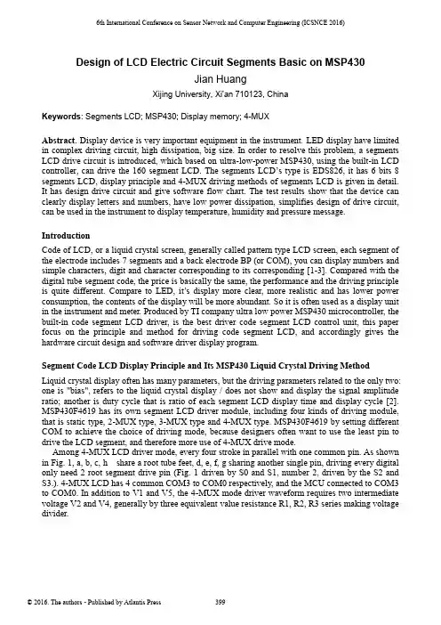
6th International Conference on Sensor Network and Computer Engineering (ICSNCE 2016)Design of LCD Electric Circuit Segments Basic on MSP430Jian HuangXijing University, Xi'an 710123, ChinaKeywords: Segments LCD; MSP430; Display memory; 4-MUXAbstract. Display device is very important equipment in the instrument. LED display have limited in complex driving circuit, high dissipation, big size. In order to resolve this problem, a segments LCD drive circuit is introduced, which based on ultra-low-power MSP430, using the built-in LCD controller, can drive the 160 segment LCD. The segments LCD’s type is EDS826, it has 6 bits 8 segments LCD, display principle and 4-MUX driving methods of segments LCD is given in detail. It has design drive circuit and give software flow chart. The test results show that the device can clearly display letters and numbers, have low power dissipation, simplifies design of drive circuit, can be used in the instrument to display temperature, humidity and pressure message. IntroductionCode of LCD, or a liquid crystal screen, generally called pattern type LCD screen, each segment of the electrode includes 7 segments and a back electrode BP (or COM), you can display numbers and simple characters, digit and character corresponding to its corresponding [1-3]. Compared with the digital tube segment code, the price is basically the same, the performance and the driving principle is quite different. Compare to LED, it’s display more clear, more realistic and has lower power consumption, the contents of the display will be more abundant. So it is often used as a display unit in the instrument and meter. Produced by TI company ultra low power MSP430 microcontroller, the built-in code segment LCD driver, is the best driver code segment LCD control unit, this paper focus on the principle and method for driving code segment LCD, and accordingly gives the hardware circuit design and software driver display program.Segment Code LCD Display Principle and Its MSP430 Liquid Crystal Driving MethodLiquid crystal display often has many parameters, but the driving parameters related to the only two: one is "bias", refers to the liquid crystal display / does not show and display the signal amplitude ratio; another is duty cycle that is ratio of each segment LCD display time and display cycle [2]. MSP430F4619 has its own segment LCD driver module, including four kinds of driving module, that is static type, 2-MUX type, 3-MUX type and 4-MUX type. MSP430F4619 by setting different COM to achieve the choice of driving mode, because designers often want to use the least pin to drive the LCD segment, and therefore more use of 4-MUX drive mode.Among 4-MUX LCD driver mode, every four stroke in parallel with one common pin. As shown in Fig. 1, a, b, c, h share a root tube feet, d, e, f, g sharing another single pin, driving every digital only need 2 root segment drive pin (Fig. 1 driven by S0 and S1, number 2, driven by the S2 and S3.). 4-MUX LCD has 4 common COM3 to COM0 respectively, and the MCU connected to COM3 to COM0. In addition to V1 and V5, the 4-MUX mode driver waveform requires two intermediate voltage V2 and V4, generally by three equivalent value resistance R1, R2, R3 series making voltage divider.Figure 1. 4-MUX LCD defineDrive Circuit DesignThe driving hardware circuit mainly includes MSP430 and its peripheral circuit and liquid crystal EDS826 module. The EDS826 can display 6 digits, so MSP430 only need to select S0 ~ S11 pins. We can use the button to adjust the display contents of the LCD liquid crystal.MSP430 Introduce. The main control unit is MSP430 single chip microcomputer, because the 430 single chip microprocessor is a high performance single chip microcomputer, its power consumption is low, the interface is rich, especially suitable for the main control unit in the instrument. Because MSP430 microcontroller internal LCD controller can automatically produce all the timing of LCD through the hardware, we only need to operate the LCD control register to select the LCD driver mode [4-6]. In software design, we need to write the display buffer, it can directly control the LCD light off or light on.LCD Module EDS826. LCD module uses EDS826, it can display six digits one time, each figure and its corresponding segment code shown in Fig. 2, the LCD module using 4-MUX drive [7-8]. In the design of the hardware circuit, the actual connection diagram is shown in Fig. 3. EDS826 COM0~ COM3 connected to MSP430 COM0 ~ COM3, all other pins are connected in sequence to S0 ~ S11, according to 4-MUX driving principle, S0 and S1 driving the first tube, S2 and S3 driving the second tube, by analogy, S10, S11 drive the sixth tube. The relationship between the memory and the segment code referring to the front of this paper [7].Figure 2. EDS826 pinsFigure 3. EDS826 connected to MCUSoftware ProgramSoftware Flow Chart. Software flow chart as shown in Fig. 4, first initialization LCD, then according to the above macro definition to display 0 to 5, finally we can change the display numbers through the button.Figure 4. Software flow chartPart Code. Code below can display number 0 to 5. Compiler development environment is IAR5.0.LCDACTL = LCDON+LCD4MUX+LCDFREQ_128; // 4mux LCD,LCDAPCTL0 =LCDS0+LCDS4+LCDS8; //Segments 0-11for (i=1;i<7;i++){LCDMEM[i] = char_gen[i];}Test ResultsAccording to the above description,we design the hardware circuit and software program[9], display the results as shown in Fig. 5 and Table 1Figure 5. Display resultTable 1 The code of number 0~9ConclusionThis paper describes the principle and method of the segment code LCD in detail, using MSP430F4619 to drive the segment code LCD screen EDS826, drawing the schematic and the PCB board, using c language to program the code. Experimental results show that the digital 0 to 9 can be display clearly. According to the driving method [10], the LCD can be driven more segments, and can be used to display important information in the instrument and meter equipment. References[1]Lin Fanqiang, Ma Xiaoming. Design of the segment type LCD driver, liquid crystal anddisplay [J].2012,27 (4): 523-528[2]Li Yujie. The design of the logistics safety data recorder based on MSP430 MCU [J] displaydesign.2013,32, logistics technology LCD (4): 100-102[3]Ge Huamin, Zheng Jing, Yang Liqing. Design of LCD display module based on ARM-Linux[J], instrument technology and sensor.2009,7:75-77[4]Su peace, Chi Ke. A design method for direct driven character type [J] LCD, instrumenttechnology and sensor.2004,2:35-37[5]Xie Zhao, Zhao Jian.MSP430 Series MCU system engineering design and practice [M].Machinery Industry Press, 2009[6]Texas Instruments.MSP430x4xx Family [6] s User Guide [M]. January 2010[7]EDS826 sheet. DALIAN data GOOD DISPLAY CO. LTD,, 2012[8]Tang Sichao. Embedded system software design based on Embedded Workbench [M]. IARBeijing: Beihang University press, 2010[9]Zhang Yongbin, Hu Jingao. Control and design of LCD display based on [J]. DSP LCD anddisplay.2011, 26 (5): 626-630.[10]Wang Xinxin, Xu Jiangwei, et al. Research on TFT-LCD defect detection system [J]. Journalof electronic measurement and instrument.2014, 28 (3): 278-284.[11]Y.G. Sun, W.L. Li, D.S. Dong, X. Mei, H.Y. Qiang, “Dynamics Analysis and Active Control ofa Floating Crane”, Tehnicki Vjesnik-Technical Gazette, vol.22, no. 6, pp. 1383-1391, 2015.。
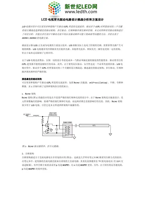
LCD电视背光驱动电路设计挑战分析和方案设计LCD电视应用中可以采用多种架构产生驱动CCFL所需的交流波形,驱动多个CCFL时所要面对的三个关键的设计挑战是选择最佳的驱动架构、多灯驱动、灯频和脉冲调光频率控制。
本文对四种常用驱动架构进行了对比分析,并提出多灯设计中解决亮度不均以及驱动频率可能干扰画面等问题的方法,并给出基于DS3984/DS3988的电路方案。
液晶显示器(LCD)正在成为电视的主流显示技术。
LCD面板实际上是电子控制的光阀,需要靠背光源产生可视的图像,LCD电视通常用冷阴极荧光灯提供光源。
其他背光技术,例如发光二极管也受到一定的重视,但由于成本过高限制了它的应用。
由于LCD电视是消费品,压倒一切的设计考虑是成本—当然必须满足最低限度的性能要求。
驱动背光灯的CCFL逆变器不能明显缩短灯的寿命。
此外,由于要用高压驱动,安全性也是一个必须考虑的因素。
LCD电视应用中,驱动多个CCFL时所要面对的三个关键的设计挑战是:挑选最佳的驱动架构;多灯驱动;灯频和脉冲调光频率的严格控制。
挑选最佳的驱动架构可以用多种架构产生驱动CCFL所需的交流波形,包括Royer(自振荡,self-oscillating)、半桥、全桥和推挽。
表1详细归纳了这四种架构各自的优缺点。
1. Royer架构Royer架构(图1)的最佳应用是在不需要严格控制灯频和亮度的设计中。
由于Royer架构是自振荡设计,受元件参数偏差的影响,很难严格控制灯频和灯电流,而这两者都会直接影响灯的亮度。
因此,Royer架构很少用于LCD电视,尽管它是本文所述四种架构中最廉价的。
图1:Royer驱动器简单,但不太精确。
2.全桥架构全桥架构最适合于直流电源电压非常宽的应用(图2),这就是几乎所有笔记本PC都采用全桥方式的原因。
在笔记本中,逆变器的直流电源直接来自系统的主直流电源,其变化范围通常在7V(低电池电压)至21V(交流适配器)。
有些全桥方案要求采用p沟道MOSFET,比n沟道MOSFET更贵。
毕业设计(论文)任务书基于FPGA的LCD驱动显示电路的设计与实现摘要本课题主要任务是设计基于FPGA的LCD驱动电路的设计和实现,兼顾好程序的易用性,以方便之后模块的移植和应用。
控制器部分采用Verilog语言编写,主体程序采用了状态机作为主要控制方式。
最后实现使用FPGA在LCD上显示任意的英文字符和阿拉伯数字,另外要能根据输入数据的变化同步变化LCD上显示的内容。
同时要能将储存模块中的数据正常地显示在LCD上。
该课题的研究将有助于采用FPGA的系列产品的开发,特别是需要用到LCD的产品的开发。
同时可以大大缩短FPGA的开发时间。
另外,由于模块的易用性,也将使得更多的采用FPGA的产品之上出现LCD,增加人机之间的交互性,为行业和我们的生活带来新的变化。
本文中对FPGA,LCD,ModelSim,Xilinx ISE8.2i硬件设计工具等进行了简单的介绍,对其功能进行了简单的描述,并了解了LCD液晶显示器的发展历史,日常应用以及相对比于其他种类显示器的优缺点,并对基于FPGA的LCD液晶显示器驱动电路未来的发展趋势进行了展望。
关键词:FPGA,LCD,状态机,VerilogDesign and Implementation of LCD Drive DisplayCircuit based on FPGAAbstractIn this project, the main object is to design a LCD controller based on FPGA, and at the same time emphasize on the convenience for the later application and migration.The program of the controller is written by Verilog language, and the main body of the program used state machine as the primary control method. displayed picture which was put earlier.In this project, I finally realized the following function. The first one is to display any English and figureon character any position of the display screen. The second one is the display information will instantaneously update as the input data changes.The research of this project will contribute to the developing process of those products which use FPGAs, especially those products also use LCD. And at the same time, it can reduce dramatically on the developing time. In addition, for the convenience of this controller, more and more FPGA based products will come out with LCD screen. This change will enhance the interaction between human and the machine, and bring innovation to the industry and our lives.In this project, FPGA, LCD, ModelSim, Xilinx ISE8.2 I hardware design tools simply introduces its functions were a simple description, and understanding the LCD monitor the development history, and relative everyday applications than in other types of monitor based on FPGA advantages and disadvantages, and the LCD monitor driver circuit future development trends are discussed.Key words:, FPGA, LCD, State Machine, Verilog目录任务书 (I)摘要 ....................................................错误!未定义书签。
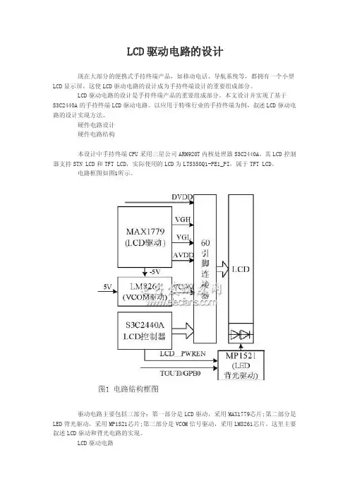
LCD显示屏的器件选择和驱动电路设计如何实现LCD平板显示屏驱动电路的高性能设计是当前手持设备设计工程师面临的重要挑战。
本文分析了LCD显示面板的分类和性能特点,介绍了LCD显示屏设计中关键器件L DO和白光LED的选择要点,以及电荷泵LED驱动电路的设计方法。
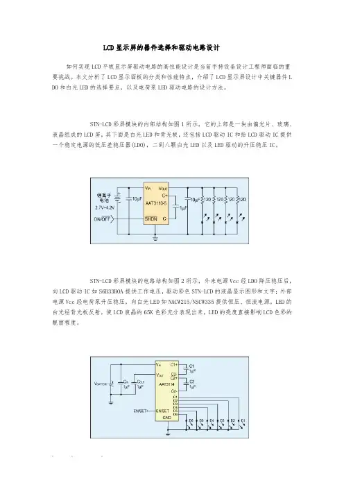
STN-LCD彩屏模块的内部结构如图1所示,它的上部是一块由偏光片、玻璃、液晶组成的LCD屏,其下面是白光LED和背光板,还包括LCD驱动IC和给LCD驱动IC提供一个稳定电源的低压差稳压器(LDO),二到八颗白光LED以及LED驱动的升压稳压IC。
STN-LCD彩屏模块的电路结构如图2所示,外来电源Vcc经LDO降压稳压后,向LCD驱动IC如S6B33BOA提供工作电压,驱动彩色STN-LCD的液晶显示图形和文字;外部电源Vcc经电荷泵升压稳压,向白光LED如NACW215/NSCW335提供恒压、恒流电源,LED的白光经背光板反射,使LCD液晶的65K色彩充分表现出来,LED的亮度直接影响LCD色彩的靓丽程度。
LCD属于平板显示器的一种,按驱动方式可分为静态驱动(Static)、单纯矩阵驱动(Simple Matrix)以及有源矩阵驱动(Active Matrix)三种。
其中,单纯矩阵型又可分为扭转式向列型(Twisted Nematic,TN)、超扭转式向列型(Super Twisted Nematic,STN),以及其它无源矩阵驱动液晶显示器。
有源矩阵型大致可区分为薄膜式晶体管型(ThinFilmTr ansistor,TFT)及二端子二极管型(Metal/Insulator/Metal,MIM)两种。
TN、STN及TFT型液晶显示器因其利用液晶分子扭转原理的不同,在视角、彩色、对比度及动画显示品质上有优劣之分,使其在产品的应用范围分类亦有明显差异。
以目前液晶显示技术所应用的范围以及层次而言,有源矩阵驱动技术是以薄膜式晶体管型为主流,多应用于笔记本电脑及动画、影像处理产品;单纯矩阵驱动技术目前则以扭转向列以及STN为主,STN液晶显示器经由彩色滤光片(colorfilter),可以分别显示红、绿、蓝三原色,再经由三原色比例的调和,可以显示出全彩模式的真彩色。
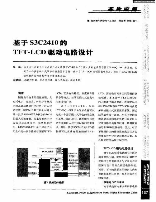
TFT—LCD显示及驱动电路的设计TFT-LCD显示及驱动电路的设计是一项关键的技术,它在各种电子设备中得到广泛的应用,包括手机、平板电脑、电视等。
本文将简要介绍TFT-LCD显示及驱动电路的设计原理和关键技术。
TFT-LCD显示屏是由许多像素组成的矩阵,每个像素由红、绿、蓝三个基本颜色的像素点组成,显示出各种颜色和图像。
TFT-LCD显示屏的设计需要考虑到图像的清晰度、亮度、饱和度和对比度等因素。
TFT-LCD显示屏的设计包括以下几个方面:像素结构设计、矩阵驱动电路设计、行驱动电路设计、列驱动电路设计和背光源驱动电路设计。
首先是像素结构设计。
像素是显示屏的基本单元,它由透明导电层、液晶层和像素电路组成。
透明导电层起到控制像素点亮度的作用,液晶层负责调节像素的透明度,像素电路则负责控制液晶的偏振状态。
像素结构设计需要考虑像素点的大小、形状和排布等因素,并保证像素之间的间距足够小,以避免显示图像失真。
其次是矩阵驱动电路设计。
矩阵驱动电路是控制像素点亮度和颜色的关键。
它采用行列扫描的方式,通过逐行、逐列地刷新像素,将电信号转换为液晶的偏振状态。
矩阵驱动电路主要由行驱动电路和列驱动电路组成,它们分别控制液晶的行和列,使其呈现出不同的亮度和颜色。
行驱动电路设计需要考虑驱动电压和扫描速度等因素,以确保像素能够按时刷新。
列驱动电路则负责将外部信号转换为适合液晶的信号,以控制像素的亮度和颜色。
背光源驱动电路设计是TFT-LCD显示屏设计中的另一个重要部分。
背光源驱动电路主要负责控制显示屏的亮度和对比度。
常见的背光源驱动电路有LED背光源驱动电路和CCFL背光源驱动电路。
LED背光源驱动电路可以提供更高的亮度和更长的寿命,但成本较高。
CCFL背光源驱动电路成本较低,但亮度和寿命相对较低。
最后,TFT-LCD显示屏的设计还需要考虑显示控制器和数据接口的设计。
显示控制器负责接收和处理外部信号,并将其转换为适合显示屏的信号。
LCD驱动电路的设计LCD(液晶显示器)驱动电路是将输入信号转换为可供液晶显示的控制信号的关键部分。
为了设计一个高效且可靠的LCD驱动电路,以下是一些关键要点和设计原则。
1.了解液晶显示器的特性:液晶显示器是一种非线性设备,其工作需要复杂的信号驱动和控制电路。
因此,对液晶显示器的工作原理和特性有深入的了解至关重要。
2.确定分辨率和色彩深度:首先确定液晶显示器的分辨率和色彩深度,这将决定驱动电路所需的处理能力和存储资源。
3.选择适当的控制器芯片:根据液晶显示器的要求,选择适当的控制器芯片。
芯片应支持所需的分辨率和色彩深度,并具有相应的接口,如VGA、HDMI或LVDS。
4.驱动和控制信号:根据所选择的控制器芯片,确定所需的驱动和控制信号。
这些信号可能包括时钟信号、数据信号、纵横线扫描信号等。
5.调整和校正电路:由于液晶显示器像素之间的差异,需要使用校正电路来确保显示的准确性和一致性。
这些校正电路可能包括背光补偿电路、像素补偿电路等。
6.电源管理:在设计LCD驱动电路时,必须考虑电源管理。
确保提供稳定的电源和正确的功率分配是确保LCD正常工作的关键。
7.EMI(电磁干扰)控制:液晶显示器的电路可能产生电磁干扰,特别是由于高速时钟和数据信号。
为了控制EMI,需要使用滤波器、屏蔽和接地路径的良好设计。
8.PCB设计:良好的PCB设计对于LCD驱动电路的性能和可靠性至关重要。
确保信号完整性,减少EMI和最小化功耗是PCB设计的重要方面。
在设计LCD驱动电路时,还需要考虑一些关键的技术参数,如刷新率、对比度、响应时间等。
因此,了解并满足这些要求对于设计出高性能的LCD驱动电路至关重要。
TFT-LCD驱动电路的设计TFT-LCD显示器已成为现代电子产品中常见的显示方式之一。
它通常由液晶显示面板、背光源、驱动电路和信号处理器组成。
其中,驱动电路起着至关重要的作用,它能够控制液晶的各个像素点的颜色和亮度,从而实现不同的显示效果。
本文将从驱动电路的设计方面入手,介绍TFT-LCD驱动电路的设计。
一、驱动电路基本原理TFT-LCD显示器的驱动电路是由数字信号驱动模拟信号的芯片构成的,其基本原理是将数字信号转换成模拟信号,再将模拟信号输出到液晶显示面板上。
驱动电路通常需要满足以下几个要求:1. 快速响应:驱动电路需要在短时间内对信号进行响应,以确保液晶显示面板的刷新率和稳定性。
2. 显示效果优秀:驱动电路需要能够高效地控制液晶显示面板的各个像素点的颜色和亮度,从而实现不同的显示效果。
3. 低功耗:驱动电路需要尽可能地降低功耗,以确保显示器的长时间使用。
二、驱动电路设计过程1. 信号处理器接口设计信号处理器通常是数字信号,一般为LVDS或TTL信号。
我们需要设计一个将信号处理器输出的数字信号转换为液晶显示面板能够接受的模拟信号的接口电路。
其中,LVDS接口通常需要使用LVDS转换器芯片和数据转换配置文件;TTL接口通常需要使用TTL驱动器芯片和电平转换电路。
2. 驱动电路选择对于TFT-LCD显示器的驱动电路选择,通常需要考虑到驱动电路的可靠性、成本和显示效果。
市面上常用的驱动电路有AMLCD、DVP、RSDS和LVDS等。
其中,LVDS驱动电路具有高速传输、低功耗和抗干扰性强等优点,因此被广泛应用。
3. 液晶显示面板控制电路设计液晶显示面板控制电路是驱动电路的关键部分。
其主要功能是对液晶显示面板的各个像素点进行控制,实现不同颜色和亮度的显示效果。
因此,我们需要根据液晶显示面板的特点设计控制电路,包括对各像素点的偏置电压和扫描电压的控制。
4. 背光源电路设计背光源是液晶显示器中为显示内容提供光源的部分。
lcd驱动方案一、背景介绍液晶显示(Liquid Crystal Display,简称LCD)是一种使用液晶材料来控制光的传播和封锁,实现图像显示的技术。
在现代电子产品中广泛应用,如智能手机、电视、电脑显示器等。
而实现液晶显示的关键则是驱动方案。
二、LCD驱动方案的重要性LCD驱动方案是决定显示效果和稳定性的关键因素之一,不同的驱动方案会对显示画质、响应速度、功耗等产生显著影响。
因此,选择合适的LCD驱动方案对产品性能和用户体验至关重要。
三、常见的LCD驱动方案1. 静态驱动静态驱动是指每个像素点的驱动电极一直保持高或低电平,由控制器时钟信号确定像素点ON和OFF的状态。
静态驱动电路结构简单,成本较低,但在动态切换画面时存在响应时间较长的问题。
2. 时分复用(TDM)驱动时分复用驱动是通过控制液晶模块的存储电容,使用不同的电压信号和持续时间来驱动像素点。
这种驱动方式有效地减少了连接到控制器的总线数量,提高了像素点的刷新速度,但会对驱动电路和控制器产生一定的复杂性和成本增加。
3. 轮询驱动轮询驱动是通过控制器按照某种顺序逐个驱动液晶模块的像素点,不同的像素点在一段时间内响应不同的驱动电压信号,从而形成图像。
这种驱动方式可以有效地控制LCD的亮度,较为常用。
4. 行列驱动行列驱动是一种采用驱动交替的方式,通过控制器中的行选通和列选通信号来控制每个像素点的ON和OFF状态。
这种驱动方式广泛应用于LCD面板,具有驱动简单、成本低、刷新速度快等优点。
四、如何选择适合的LCD驱动方案在选择LCD驱动方案时,需根据产品的实际需求和预算来考虑。
以下几个方面可供参考:1. 显示效果:不同的驱动方案对显示效果有不同影响,如亮度、对比度、响应速度等。
需要根据产品的目标市场和用户需求来选择合适的方案。
2. 功耗:液晶显示对功耗要求较高,选择低功耗的驱动方案可以延长电池寿命或降低能耗。
3. 成本:LCD驱动方案的成本直接影响产品价格和市场竞争力。
小型LCD背光的LED驱动电路设计小型LCD背光的LED驱动电路设计过去几年来,小型彩色LCD 显示屏已经被集成到范围越来越宽广的产品之中。
彩色显示屏曾被视为手机的豪华配置,但如今,即便在入门级手机中,彩屏已成为一项标配。
幸好,手机产业的经济规模性(全球手机年出货量接近10 亿部)降低了LCD 彩色显示屏的成本,并使它们集成在无论是便携医疗设备、通用娱乐遥控器、数字相框/彩色LCD 显示屏需要白色背光,以便用户在任何光照环境下都能正常地观看。
这个背光子系统包括1 个高亮度白光发光二极管(LED)阵列、1 个扩散器(diffuser)以扩散光线和1 个背光驱动器将可用电能稳压为恒定电流以驱动LED.一块1 到1.5 英寸的显示屏可能包含2 到4 个LED,而一块3.5 英寸显示屏则可能轻易地就包含6 到10 个LED.对于LED 而言,其光输出与电流成正比,而且由于LED 具有非常陡峭的电流-电压(I-V)曲线,流过LED 的电流紧密匹配是非常重要,这样才能确保均衡背光,因为LED 通常分布在LCD 显示屏的一边。
此外,也需要软件控制让用户调节亮度,以及针对周围光照环境作出补偿。
根据流经LED 电流的不同,LED 的色点(color point) 可能会漂移。
因此,将LED 电流设定为固定值并对LED 进行脉宽调制以降低平均光输出就很普遍。
要在手持产品设计中集成小型彩色LCD 显示屏并进而实现成本、性能和电池寿命的恰当平衡,存在着一系列需要考虑的因素。
电池供电产品需要优化的LED 驱动电路架构,这些架构要处理并存的多项挑战,如空间受限、需要高能效,以及电池电压变化-既可能比LED 的正向电压高,也可能低。
常用的拓扑结构有两种,分别是LED 采用并联配置的电荷泵架构/恒流源架构和LED 采用串联配置的电感升压型架构。
这两种方案都有需要考虑的折衷因素,如升压架构能够确保所有LED 所流经的电流大小相同但需要采用电感进行能量转换,而电荷泵架构使用小型电容进行能量转换,。
图 1.LCD 静态驱动示意图图 2.驱动电路原理图驱动波形根据此电信号,笔段波形不是与公用波形同相就是反相。
同相时液晶上无电场,L C D 处于非选通状态。
反相时,液晶上施加了一矩形波。
当矩形波的电压比液晶阈值高很多时,L C D 处于选通状态。
图 3.静态波形£2. 多路驱动基本思想电极沿X、Y方向排列成矩阵(如图4),按顺序给X电极施加选通波形,给Y电极施加与X电极同步的选通或非选通波形,如此周而复始。
通过此操作,X、Y电极交点的相素可以是独立的选态或非选态。
驱动X电极从第一行到最后一行所需时间为帧周期T f(频率为帧频),驱动每一行所用时间T r与帧周期的比值为占空比:D u t y=T r/T f=1/N。
图 4.电极阵列电压平均化从多路驱动的基本思想可以看出,不仅选通相素上施加有电压,非选通相素上也施加了电压。
非选通时波形电压与选通时波形电压之比为偏压比B i a s=1/a。
为了使选通相素之间及非选通相素之间显示状态一致,必须要求选点电压V o n一致,非选点电压V o f f一致。
为了使相素在选通电压作用下被选通;而在非选通电压作用下不选通,必须要求L C D的光电性能有阈值特性,且越陡越好。
但由于材料和模式的限制,L C D电光曲线陡度总是有限的。
因而反过来要求V o n、V o f f 拉得越开越好,即V o n/V o f f越大越好。
经理论计算,当D u t y、B i a s满足以下关系时,V o n/V o f f取极大值。
满足下式的a,即为驱动路数为N的最佳偏压值。
六级电平驱动在半导体集成电路中,实现最佳偏压一般采用如图5所示的六级电平方式。
图 5.六级电平图 6.六级电平的电路原理图实现六级电平的电路一般采用如图6的B i a s电路。
六级电平驱动时,给于C O M电极和S E G电极的电平如下表:上叙6级电平,当a<5时,会发生简并。
如:∙a=4时,V3=V4∙a=3时,V2=V4,V3=V5∙a=2时,V1=V4,V2=V5,V3=V6简并后,上表中的电平分配关系依然成立。