电接点说明书
- 格式:doc
- 大小:430.00 KB
- 文档页数:10
Quick Start GuideCisco WAP361 Wireless-AC/N Dual Radio Wall Plate Access Point with PoEWelcomeThank you for choosing the Cisco WAP361 Wireless-AC/N Dual Radio Wall Plate Access Point with PoE. The Cisco WAP361 is an indoor concurrent dual-band radio 802.11ac and 802.11n access point with integrated PoE switch. -PoE Supplied by UL Listed I.T.E.This guide provides the general layout of the Cisco WAP361, describe how to deploy the Cisco WAP361 in your network, and describe how to configure the Cisco WAP361. For additional information, see/go/300_wap_resources.Package Contents•Wireless Access Point•Mounting Kit•This Quick Start Guide•Ethernet Cable•T echnical Support Contact•Pointer Card China RoHS•EU Directives 1999/5/EC Compliance Information (for EU SKU only) Before You Begin1Before you begin the installation, make sure that you have the following equipment and services:• A computer with browser support for:–Internet Explorer 7.0 or later–Chrome 5.0 or later–Firefox 3.0 or later–Safari 3.0 or later•T ools for installing the hardware•FindIt tool for locating the access point•One or more Ethernet network switches with PoE•Mobile devices (iPhone, Android, etc.) via wireless setup SSID.(Configure via Wi-Fi mobile device with a web browser.)2Cisco WAP361 Quick Start GuideCisco WAP361 Features2Front PanelThe front panel of the Cisco WAP361 consists of one system LED. For full descriptions of the colors of the lights and their indications, see “Verifying the Hardware Installation”.Back PanelRESET—See “Rebooting the Cisco WAP361 or Resetting to Factory Defaults” for information on the RESET button.PD/LAN0—The Powered Device (PD/LAN0) port is used to power the Cisco WAP361 using PoE.Right-Side PanelThe right-side panel of the Cisco WAP361 has a Kensington lock slot. You can use it to attach a cable and lock to the Cisco WAP361.48V DC—The 48V DC jack is used to connect the power adapter to the Cisco WAP361 if you are not using PoE.Top PanelThe top panel of the Cisco WAP361 has the security screw hole.Bottom PanelPSE—The Power Sourcing Equipment (PSE) port is used to power the device that is connected to the Cisco WAP361 through this port.LAN1-4—The RJ-45 Ethernet port is an auto-sensing, Gigabit Ethernet (802.3) port used to connect the Cisco WAP361 to network devices, such as computers, routers, or switches. We strongly recommend that you use a Category 5e or better cable for gigabit connectivity.Default SettingsParameter Default ValueUsername ciscoPassword ciscoLAN IP Address DHCP address assigned by serverFallback LAN IP192.168.1.245Subnetwork Mask255.255.255.0Cisco WAP361 Quick Start Guide34Cisco WAP361 Quick Start GuideIf you are using a Cisco RV series router, the default range for the DHCP assigned address is from 192.168.1.100 to 192.168.1.254. Any device connecting to the same LAN will be assigned an IP address in this range.Mounting the Cisco WAP361•We recommend that you mount the Cisco WAP361 to a wall or junction box.Placement Tips•Ambient Temperature —T o prevent the Cisco WAP361 fromoverheating, do not operate it in an area that exceeds an ambient temperature of 104°F (40°C).•Air Flow —Both side panels have vents that must be unobstructed to prevent overheating.•Mechanical Loading —The Cisco WAP361 should be level, stable, and secure to prevent it from sliding or shifting out of position.Wall MountingCisco WAP361 access points can be mounted on walls and junctionboxes, in the vertical orientation with the security screw on the top and the LED which is located above the Cisco logo.3Cisco WAP361 Quick Start Guide 5S TEP 1If you are mounting the AP directly to a junction box, go to Step 3.For wall mounting, use the mounting bracket as a template to mark the locations of the mounting holes on the bracket. Figure 1 shows the dimensions of the mounting bracket.C AUTION T o ensure a safe and secure installation, make sure you are using adequate screws and mount the access point using noless than two screws.Figure 1Mounting Bracket DimensionsS TEP2For wall mounting, drill four pilot holes at the mounting hole locations you have marked (at opposite corners of the bracket),and use appropriate anchors as required.N OTE The pilot hole size varies according to the material, and itsthickness, you are fastening. Cisco recommends that you test thematerial to determine the ideal hole size for your mountingapplication.S TEP3Feed the cable(s) from the junction box / wall through the large center cable access hole in the bracket, with the words “NOTICEWALL MOUNT ONL Y” facing you as shown in Figure2.Figure2Bracket Mounting DirectionS TEP4Position the mounting bracket mounting holes (with the words “NOTICE WALL MOUNT ONL Y” facing you) over the screw holes.S TEP5Insert a screw into each mounting hole and tighten.N OTE Screws supplied in kit (see Figure3) may not be appropriatefor all mounting options. You may need to obtain screws which fityour custom installation.6Cisco WAP361 Quick Start GuideCisco WAP361 Quick Start Guide 7Figure 3Mounting Bracket Screw DimensionsN OTE Make sure all cables are clear and the bracket sits flushagainst the wall / junction box. The joint created with the screwsmust have a minimum pullout force of 20 lbs (9 kg).S TEP 6Connect the Ethernet cable and the power cable (optional) to theaccess point.S TEP 7With the access point’s LAN1-4 ports facing down and the rearmetal side of the access point facing the bracket, gently slide the access point onto the bracket. If properly done, the Kensingtonlock slot on the AP and the security screw hole on the mountingbracket will be aligned.S TEP 8Insert the security screw (see Figure 4) into the hole on the top ofthe access point and tighten it till the screw head is flush with the access point's body (see Figure 2). The security screw isprovided in the Mounting Kit.Figure 4Security Screw DimensionsAll dimensions in millimeters (mm).Connecting the Cisco WAP3614You can perform the initial configuration using either a wired or wireless connection. The default configuration of the Cisco WAP361 has the Wi-Fi radio turned on.T o connect the Cisco WAP361 to the wired network:S TEP1Connect the Ethernet cable to the Ethernet port of a switch, a router, or a PC.S TEP2Connect the other end of the network Ethernet cable to the Ethernet port of the Cisco WAP361.S TEP3If PoE is not provided, plug in the supplied power adapter to provide power to the Cisco WAP361.This wireless default configuration will not allow traffic between WiFi and Ethernet; users will need to go through the setup wizard to resume the traffic between WiFi and Ethernet.T o connect the Cisco WAP361 to the network wirelessly:S TEP1Use wireless clients to locate the WAP361’s SSID (CiscoSB-Setup). S TEP2Use the ‘cisco123’ passkey to access the access point.N OTE The system provides a one-time-only access to configure the access point using a wireless connection.After installation, all lights should be active. Refer to Verifying the Hardware Installation for details about the different lights on the Cisco WAP361.8Cisco WAP361 Quick Start GuideCisco WAP361 Quick Start Guide 9Verifying the Hardware InstallationT o verify the hardware installation, complete the following tasks:•Check the cable connections.•Check the state of the indicator light.N OTE If you need help resolving a problem, visit the Cisco Support Community at /go/smallbizsupport . Label Activity Description Power OffThe WAP361 is out of power.Solid GreenThe Cisco WAP361 is normal; no wireless client connected.Solid BlueThe Cisco WAP361 is normal; at least one wireless client connected.Solid RedThe Cisco WAP361 fails to boot with both firmware images.Flashing GreenThe Cisco WAP361 is booting.Flashing BlueFirmware upgrade is in N0-4OffNo Ethernet link.Solid GreenGigabit Ethernet link is active. Solid AmberFast Ethernet link is active.Flashing Transmitting or receiving data.5Getting Started with the Configuration6T o configure the Cisco WAP361, follow these steps to access the the web-based Configuration Utility and then the Setup Wizard from your computer: S TEP1Connect the Cisco WAP361 to the same network (IP subnet) as your computer. The factory default IP address configuration of the CiscoWAP361 is DHCP. Make sure that your DHCP server is running andcan be reached.See “Incorrect IP Address” for troubleshooting information, or ifyou do not have a DHCP server.S TEP2Locate the IP address of the Cisco WAP361.a.The Cisco WAP361 can be accessed and managed by Cisconetwork tools and services including the Cisco FindIT NetworkDiscovery Utility that enables you to automatically discover allsupported Cisco devices in the same local network segmentas your computer. You can get a snapshot view of each deviceor launch the product configuration utility to view andconfigure the settings. For more information, see/go/findit.b.The Cisco WAP361 is Bonjour-enabled and automaticallybroadcasts its services and listens for services beingadvertised by other Bonjour-enabled devices. If you have aBonjour-enabled browser, such as Microsoft Internet Explorerwith a Bonjour plug-in, or the Apple Mac Safari browser, youcan find the Cisco WAP361 on your local network withoutknowing its IP address.You can download the complete Bonjour for Microsoft InternetExplorer browser from Apple’s website by visiting:/bonjour/c.Locate the IP address assigned by your DHCP server byaccessing your router or DHCP server. See your DHCP serverinstructions for more information.S TEP3Launch a web browser, such as Microsoft Internet Explorer.S TEP4In the address bar, enter the default DHCP address and press the Enter key.S TEP5Enter the default user name of cisco and password of cisco in the Username and Password fields.S TEP6Click Log In. The Wireless Access Point Setup Wizard appears.10Cisco WAP361 Quick Start GuideS TEP7Follow the Setup Wizard instructions to finish the WAP device installation.We strongly recommend that you use the Setup Wizard for the firstinstallation. For more advanced configurations, see theAdministration Guide. A link to the Administration Guide is found in“Where to Go From Here”.Congratulations, you can now start using the Cisco WAP361.Suggested Next Steps7In case of an error while installing, try the troubleshooting procedures described in this section.TroubleshootingIf you cannot display the web-based Configuration Utility, you can test the ability of the computer to communicate with the Cisco WAP361 by using ping.T o use ping on a computer running Windows:S TEP1Verify that the Cisco WAP361is powered on and the lights if they do not indicate the appropriate links.S TEP2Locate the Cisco WAP361’s IP address. While there are different ways to locate the IP address, this procedure uses Cisco FindIT.a.If you have previously downloaded Cisco FindIT, open InternetExplorer and launch Cisco FindIT. For more information ondownloading Cisco FindIT, see /go/findit.b.In the Cisco FindIT display, place your mouse over the device’sname. The Cisco WAP361’s IP address is displayed along withother device information.S TEP3Open a command window by choosing Start > Run and enter cmd.S TEP4At the command window prompt, enter ping and the Cisco WAP361’s IP address. In this example, we pinged 192.0.2.10.If successful, you should get a reply similar to the following:Pinging 192.0.2.10 with 32 bytes of data:Reply from 192.0.2.10: bytes=32 time<1ms TTL=128Cisco WAP361 Quick Start Guide11If it fails, you should get a reply similar to the following:Pinging 192.0.2.10 with 32 bytes of data:Request timed out.Possible Cause of Installation FailureNo PowerPower up the switch and your computer if they are turned off.Make sure that your PoE switch is powered on and the lights indicate that you have a link. See “Verifying the Hardware Installation”.Verify that the devices on your network are not plugged into a switchable outlet.Bad Ethernet ConnectionCheck the state of the indicator lights. See “Verifying the Hardware Installation”.Check the Ethernet cable to ensure that it is firmly connected to your devices. Devices connected by the Ethernet cable can include the WAP devices, and routers, any switches, and your computer.Verify the connected switch has auto-negotiation enabled. The Cisco WAP361 and the switch need the same negotiation parameters set.Bad ImageAfter a new firmware installation, if the POWER light is solid red, which indicates that the device fails to boot with both firmware images, contact system support; see “Where to Go From Here”.Incorrect IP AddressThe most likely cause of connectivity failure is an incorrect IP address. The Web browser may be pointing to the wrong IP address, or your computer may be configured with an IP address that is not in the same subnet as the Cisco WAP361.Because the factory default IP address configuration is DHCP, make sure that your DHCP server is running and can be reached. You may need to disconnect and reconnect the devices for them to discover their new IP addresses from the DHCP server. You can then query the DHCP server for the new IP address. See Step 2 of “Getting Started with the Configuration” for more information on how to find the DHCP address.12Cisco WAP361 Quick Start GuideIf the Cisco WAP361 does not receive a DHCP response (there is no DHCP server on your network) after 60 seconds, the Cisco WAP361 will fallback to the following default static IP address: 192.168.1.245 and a default mask of 255.255.255.0. T o reach that IP address, be sure that your computer is on the 192.168.1.xxx network.Rebooting the Cisco WAP361 or Resetting 8to Factory DefaultsTo reboot your Cisco WAP361:•If the Cisco WAP361 uses a power adapter, with the power on, use the POWER button to reboot the device. The POWER button only functions when the Cisco WAP361 uses a power adapter.•If the power supply is PoE, unplug your Ethernet connection for three seconds and plug it back in.•With the power on, press the RESET button with an opened paper clip for less than 10 seconds, or until the lights go off.–When all the lights go off, release the RESET button.–Release the RESET button as soon as the lights go off, or you will restore the Cisco WAP361 to factory default settings and lose yourconfigurations.To reset the Cisco WAP361 to factory default settings:•With the power on, press and hold the RESET button with an opened paper clip for more than 10 seconds.–All of the lights will go off.–Release the RESET button when the power light turns on.Cisco WAP361 Quick Start Guide1314Cisco WAP361 Quick Start GuideWhere to Go From HereFor EU lot 26 related test result, please check this web page:/go/eu-lot26-results . Support Cisco SupportCommunity/go/smallbizsupport Cisco Support andResources/go/smallbizhelp Phone Support Contacts /en/US/support/tsd_cisco_small_business_support_center_contacts.htmlCisco Firmware Downloads /go/smallbizfirmwareSelect a link to download firmware for Ciscoproducts. No login is required.Cisco Open Source Requests /go/smallbiz_opensource_requestCisco Partner Central(Partner Login Required)/web/partners/sell/smb Product DocumentationCisco WAP361Administration Guide/go/300_wap_resources Cisco Power Adapters /go/wap_accessories 9Cisco WAP361 Quick Start Guide15Americas HeadquartersCisco Systems, Inc.Cisco has more than 200 offices worldwide.Addresses, phone numbers, and fax numbersare listed on the Cisco website at/go/offices.78-100811-01_A0 Cisco and the Cisco logo are trademarks or registered trademarks of Cisco and/or its affiliates in the U.S. and other countries. To view a list of Cisco trademarks, go to this URL: /go/trademarks. Third-party trademarks mentioned are the property of their respective owners. The use of the word partner does not imply a partnership relationship between Cisco and any other company. (1110R)© 2015 Cisco Systems, Inc. All rights reserved.。

智能电接点液位计使用说明书江苏通达仪表有限公司一、概述智能型电接点液位计以显示直观这一特有的优点被广泛应用于锅炉汽包、汽轮机、冷凝器、高低压加热器、除氧器、蒸发器、水箱、水塔等液面的测量、显示。
该机以智能化、小型化、通用化为特点,性能更加可靠。
并有越限报警输出功能,以确保被测容器的正常工作。
二、特点1.电接点测量采用低压小电流供电方式,有效地延长了电接点的使用寿命。
2.该机电路采用89S52单片机为主,具有体积小,重量轻,耗电省,性能可靠。
3.该机采用高亮度双色LED光柱显示模拟液位(有液位为绿色;无液位为红色),直观清晰;同时设有数字液位显示。
4.该机具有自动告警电路,采用声光报警以示液位超越正常位置。
5.该机配备上、下限各三组继电器触点,供用户外接使用;亦可作为开关量输出,以确保被测容器的安全运行。
6.该机还备有标准直流信号输入和输出接口。
可参与调节控制系统,控制被测容器的液位。
三、主要技术参数(一)显示仪表(二次仪表)1.产品型号:DS--8S-----(Q、G、Y)-----液位仪标尺型号汽包高加除氧器安装方式标尺型号:见附表;安装方式:Z----竖式安装;H----横式安装;2.液体阻值范围:0~500K仪表出厂时设定至0~150K左右。
3.模拟显示:双色LED光柱显示,配合标尺刻度显示即时液位值。
4.数字显示:对应模拟显示值显示数字值。
5.报警方式:上、下限超越正常液位,被设定的报警点的LED光柱点闪烁,蜂鸣器发声。
同时报警继电器触点输出动作。
6.输入方式:a。
电接点信号。
最多19点b.模拟信号。
4~20mA;0~10mA;1~5V。
7.模拟信号输出:4~20mA;0~10mA;1~5V。
8.报警输出触点容量:AC220V,3A。
9.电源电压:AC220V±10%50Hz±1Hz。
10.消耗功率:15VA。
11.仪表工作条件:环境温度–10℃~+40℃;相对湿度≤85%;无腐蚀性气体。

使用说明书OWNER’S MANUAL智能液位监控仪LIQUIDLEVEL DISPLAY CONTROL DEVICE烟台瑞丰仪表有限公司目录Ⅰ.总述 (3)概述 (3)命名方法 (3)特点 (3)技术参数 (3)工作原理 (3)Ⅱ.智能型液位监控仪 (5)仪表连接 (5)仪表操作和设置...................................................6-7-8 Ⅲ.专用校验仪 (9)概述 (9)仪表校验 (9)Ⅳ.测量筒 (10)Ⅴ.超纯陶瓷电极 (11)Ⅵ.定货时请提供的参数 (12)附表 (13)概述 命名方法 特点概述智能通用型电接点液位监控仪是由测量筒、超纯陶瓷电极、显示仪表构成的电接点式液位测量、显示和控制仪表。
它采用红绿双色发光管在显示中模拟汽(红)水(绿),明显指示液位在容器中的位置,并具有越限报警、输出等功能。
智能电接点液位监控仪具有结构简单、显示直观、运行可靠、维修量小、判断和排除故障方便等优点。
它采用全电信号传送,不仅延时小,而且无机械传动所产生的变差和刻度误差,不需要进行误差计算和调整。
电接点液位计最突出的优点是能适应锅炉变参数运行,在锅炉起停等变参数运行工况下,仪表均能在控制室内准确地显示水位。
电接点液位监控仪适用于导电液体的液位测量和控制。
主要用于监视锅炉汽泡水位、高低压加热器、除氧器、蒸发器、凝结器、直流锅炉启动分离器和其他水箱的液位测量。
但不适用易燃易爆场合。
—一、标尺型号查附表,特殊规格可根据用户需要定制二、测量筒参数 三、安装方式01—工作压力≤6.4MPa Z —竖式安装02—工作压力≤16MPa H —横式安装03—工作压力≤20MPa04—工作压力≤22MPa特点仪表的显示部分采用模拟显示和数字显示两种方式同时进行,非常直观地即时显示水位的升降情况。
显示点数可根据用户需要在6~19点范围内任意设定。
每个标尺刻度值可通过面板操作任意设定,并可根据标尺刻度值方便地更换标尺,克服了老式仪表通用性差、不能互换、备用品规格品种要求多等缺点。
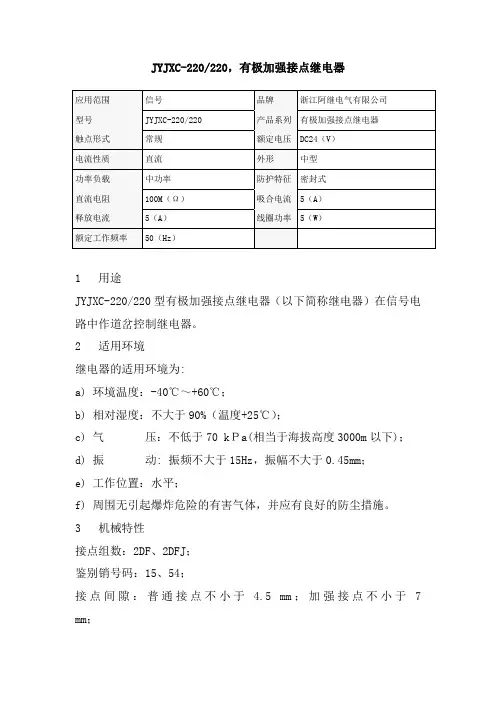
JYJXC-220/220,有极加强接点继电器1 用途JYJXC-220/220型有极加强接点继电器(以下简称继电器)在信号电路中作道岔控制继电器。
2 适用环境继电器的适用环境为:a) 环境温度:-40℃~+60℃;b) 相对湿度:不大于90%(温度+25℃);c) 气压:不低于70 kPa(相当于海拔高度3000m以下);d) 振动: 振频不大于15Hz,振幅不大于0.45mm;e) 工作位置:水平;f) 周围无引起爆炸危险的有害气体,并应有良好的防尘措施。
3 机械特性接点组数:2DF、2DFJ;鉴别销号码:15、54;接点间隙:普通接点不小于 4.5 mm;加强接点不小于7 mm;托片间隙:普通接点不小于0.35 mm;加强接点0.1 mm~0.3 mm;普通接点压力:定位接点不小于150 mN;反位接点不小于150 mN;加强接点压力:定位接点不小于400 mN;反位接点不小于400 mN;接点齐度误差:普通接点与普通接点间及普通接点与加强接点间不大于0.2 mm,加强接点与加强接点间不大于0.1 mm。
定位或反位保持力不小于2 N;3 电气特性(+20℃时)线圈电阻:线圈单独使用,使用1、23、4;额定值:;充磁值:;转极值:正向10V~16V、反向10V~16V;接点电阻:普通接点不大于0.05Ω;加强接点不大于0.1Ω。
5 绝缘耐压在试验的标准大气条件下,继电器的绝缘电阻应不小于100MΩ。
在气压不低于86kPa条件下(相当于海拔高度1000m以下),继电器的绝缘耐压应能承受交流正弦波50Hz、2000V有效值电压,历时1min 应无击穿闪络现象,重复试验时的电压应为原试验电压值的75%。
6 电寿命继电器普通接点通以DC 24V 1A 阻性负载;加强接点通以DC 220V 7.5A 、0.05H感性负载,JPXC-1000,偏极继电器1 用途JPXC-1000型偏极继电器(以下简称继电器)在信号电路中用于道岔表示电路以及单复线半自动闭塞电路。
青岛冠杰电接点压力表说明书摘要:一、产品简介二、产品用途三、产品特点四、技术参数五、安装与维护六、注意事项七、联系方式正文:青岛冠杰电接点压力表说明书一、产品简介青岛冠杰电接点压力表是一种常用的压力测量仪器,具有高精度、高可靠性、使用方便等特点,适用于各种工业生产过程中压力参数的监测和控制。
二、产品用途电接点压力表广泛应用于现代工业的工作生产,主要用于测量各种气体、液体介质的压力值,并实现上下限设定、报警等功能,为生产过程提供准确、及时的压力数据。
三、产品特点1.高精度:采用先进的磁助电接点装置,使测量结果更加精确;2.抗干扰能力强:具有优良的抗电磁干扰和抗振动性能,保证在恶劣环境下正常工作;3.使用方便:安装简单,操作方便,便于现场安装和维护;4.结构紧凑:采用一体化设计,结构紧凑,便于安装和携带;5.良好的密封性能:采用双层密封结构,保证压力表的密封性能。
四、技术参数1.测量范围:-0.1MPa~60MPa;2.精度等级:1.6%~2.5%;3.压力类型:气体、液体;4.工作电压:AC 380V或DC 220V;5.触头功率:30VA;6.连接螺纹:M201.5或其他螺纹要求;7.防护等级:IP65。
五、安装与维护1.安装时,请确保接头与被测介质充分接触,以保证测量准确性;2.使用过程中,应尽量避免振动和碰撞,以免影响测量精度;3.定期检查压力表的密封性能,如有泄漏现象,请及时更换密封圈;4.清洁压力表时,请使用潮湿的布擦拭,避免使用有机溶剂。
六、注意事项1.请勿在压力表带电状态下拆卸和维修;2.避免在高温、潮湿、腐蚀性环境中使用和存放压力表;3.使用过程中,如发现压力表有异常现象,请立即停止使用,并与我司联系。


数字电接点压力表使用说明书一、产品概述数字电接点压力表是一种用于测量流体压力,并具有电接点输出功能的工业仪表。
该仪表采用数字技术进行压力传感和信号处理,具有高精度、稳定性好、易于设置和配置等优点。
数字电接点压力表广泛应用于石油、化工、电力、环保等行业的压力控制和监测。
二、产品特点1.高精度测量:采用先进的压力传感器和信号处理技术,实现高精度的压力测量,误差范围小。
2.电接点输出:配置一组电接点,用户可根据需要设定上下限压力,实现自动控制或报警输出。
3.直观显示:采用高清晰度数码管显示,用户可直接读出测量压力值,同时了解电接点的状态。
4.配置灵活:可根据用户需求配置不同规格的传感器、电接点数量及输出类型,满足多种应用需求。
5.稳定性好:采用独特的防水设计和密封技术,保证仪表在恶劣环境下稳定工作。
6.易于操作和维护:操作面板简洁明了,方便用户设置和调整;同时,维护工作相对简单,降低使用成本。
三、使用说明1.安装与接线:a. 按照产品安装说明书的指导正确安装数字电接点压力表。
确保安装位置便于观察和操作,同时考虑必要的防护措施。
b. 正确连接电源线和电接点输出线,确保连接牢固可靠,以防发生意外事故。
2.参数设置:a. 通过操作面板或配套的软件工具,根据实际应用需求设定上下限压力值。
b. 调整电接点的控制范围和动作模式,以满足系统的控制要求。
3.运行与观察:a. 确保流体管道中充满介质,并处于正常工作状态。
b. 观察数字电接点压力表的显示值,确保其与实际压力值相符。
如有异常,应检查传感器和连接线路,必要时进行校准或维修。
4.报警与控制:a. 当实际压力超过设定的上下限时,数字电接点压力表会自动切换电接点的状态,触发报警或控制动作。
b. 根据系统要求,对数字电接点压力表的报警和控制功能进行测试和验证。
5.日常维护:a. 定期检查数字电接点压力表的外观和安装情况,确保无损坏和松动。
b. 对仪表进行定期的压力校准,以确保其测量的准确性和稳定性。
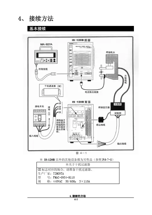
4、 接续方法基本接续※ IS-120B以外的其他设备都为另售品(参照P.9-7~8)※关于干扰过滤器CE标志对应的场合,请准备干扰过滤器。
生产厂家:TIMONTA型 号:FMAC-0954-H110规 格:440VAC 50/60Hz 3×110A接续步骤① 连接变压器请用输出电缆接续背面面板上的[焊接电源输出端子台]和焊接变压器的初级侧。
使用本公司的焊接变压器的场合请将信号电缆接续至[焊接变压器I/O信号]的接续接口上,连接焊接变压器。
使用其他公司的焊接变压器的场合请进行步骤⑤的作业。
② 连接电源用输入线缆(参照P.9-7)将焊接电源接续至背面面板的[焊接电源输入断路器]上。
请将PE端子接地。
③ 在[外部输入输出信号接续端子台]上接续必要的线缆。
请参照P.5-1准备接续用的线缆。
④连接编程操作器将回线线缆接续到正面面板的[编程操作器]接续接口上。
【使用其他公司的变压器的场合,请进行以下的操作】⑤ 连接次级电流检出用的检出线圈将检出线圈接续至正面面板的[检出线圈]接口上。
5、 接 口(1)外部输入输出信号的接续图外部输入输出信号端子台的规格额定电压 AC125V 以上耐电压 1200V 以上安装可能压着端子 最大2个压着端子尺寸 M3或M3.5(宽7.1)鼓励线缆截面积 端子No.1~5 →0.75mm 2以上 端子No.6~31→0.5mm 2以上*RY1~RY3规格型号G6B1114P(OMRON)线圈电压DC24V接点容量AC110V 0.5A(2)外部输入输出信号的说明(3)输入信号的接续方法电磁阀用电源输入为AC100V状态下使用的场合,请将1~5AC线和6~31的信号线分离后配线。
注意在下述①②③的使用场合,请根据用途接续附属的短路线。
在下述④的使用场合,请不要在6、7号接线柱上接续任何东西。
如果接续错误,会引起故障。
① 外部输入信号为接点输入的场合② 外部输入信号为接点输入的场合5. 接 口③ 外部输入信号为正COM输入的场合④ 外部电源供给输入的场合5. 接 口7、 时序图T1:[SCHEDULE]画面的[DELAY-START SET]中所设定的时间T2:约200ms(终了信号在起动信号处于ON状态期间或者200ms期间输出) T3:约80ms(此间不进行下次起动)8、 维护保养电池的更换本装置中使用的锂电池寿命为5年。
率先通过ISO9001国际质量体系认证UDZ——191A型智能电接点双色水位计使用说明书铁岭铁光仪器仪表有限责任公司TIE LING TIE GUANG INSTRUMENT&APPARATUS CO.,LTD一、产品简介UDZ-191A型智能电接点双色水位计是我公司研制的智能型仪表,由测量筒和二次表配套组成,测量筒上的电接点安装位置与二次表上的发光二极管相对应,二次表在控制室内显示水位状态,并在水位异常时进行声光报警和连锁控制。
该仪表广泛用于锅炉汽包、水箱等各种不同压力、温度的水容器上。
该二次表采用了单片机和集成电路,可进行智能分析和判断,具有性能稳定、工作可靠、维修方便等优点。
二、主要功能1、数码管和发光二极管两种显示方式。
醒目直观的显示水、汽位置,发光二极管显示水相为绿色,汽相为红色,数码管显示的水位数值与发光二极管显示的水位刻度读数一致。
2、能测量出各电极当前阻值(单位KΩ)。
3、能在各种水质环境中工作,根据测得的水、汽阻值设定相应的临界值。
4、有开机自检功能,可自动检测面板上发光二极管和数码管的好坏。
5、常用仪表可设六点上、下限报警,上限为高I、高II、高III,下限为低I 、低II、低III,水位超限时,面板上同时声光报警。
继电器均为常开触点输出供外接使用。
6、有4-20mA信号输出。
7、采取了抗干扰措施,能克服线路多,传输距离长带来的各种干扰。
8、有自充电备用电源,可在220V电源断电时,自动维持仪表正常显示液位(用户可选项,选用请在合同中注明)。
三、技术参数1、工作电压:220V+22V、50Hz 。
2、二次表工作环境温度:-10~45℃,相对湿度≤85% 。
3、继电器输出结点容量:220V、3A 。
4、整机功率:10W 。
5、二次表开孔尺寸:76mm×151mm 。
6、工作时间:连续运行。
四、测量筒的结构和功能1、工作压力:0~22MPa2、工作温度:0~540℃3、测量筒中心距:670mm或按用户要求制造4、测点位置:0,+15,+30,+50,+75,+100,+150,+200,+250,+300或按用户要求配置。
无锡信捷电气股份有限公司资料编号:MC15 20230517 1.1信捷电气AP-BOX系列无线接入点设备用户手册目录————————————————简介————————————————性能参数————————————————参数配置————————————————详细参数说明————————————————手册更新日志————————————————12345671234基本说明●感谢您购买了信捷AP-BOX系列无线接入点设备。
●本手册主要介绍AP-BOX系列产品信息。
●在使用产品之前,请仔细阅读本手册,并在充分理解手册内容的前提下,进行接线。
●请将本手册交付给最终用户。
本手册适合下列使用者参考●系统设计者●安装及配线工作者●试运行及伺服调试工作者●维护及检查工作者手册的获取途径●电子版手册登陆信捷官方网站下载。
责任申明●手册中的内容虽然已经过仔细的核对,但差错难免,我们不能保证完全一致。
●我们会经常检查手册中的内容,并在后续版本中进行更正,欢迎提出宝贵意见。
●手册中所介绍的内容,如有变动,请谅解不另行通知。
联系方式如果您有关于本产品的使用问题,请与购买产品的代理商、办事处联系,也可以直接与信捷公司联系。
●总机:*************●热线:400-885-0136●传真:*************●网址:https://●邮箱:***************●地址:江苏省无锡市滨湖区建筑西路816号WUXI XINJE ELECTRIC CO., LTD. 版权所有未经明确的书面许可,不得复制、传翻或使用本资料及其中的内容,违者要对造成的损失承担责任。
保留包括实用模块或设计的专利许可及注册中提供的所有权力。
二○二一年五月目录1. 简介 (1)1.1 功能简介 (1)1.2 功能设计 (2)1.2.1 以太网口 (2)1.2.2 重置按钮 (2)2. 性能参数 (3)2.1 尺寸及安装 (3)2.2 电源 (3)2.3 通讯端口 (4)2.4 状态指示 (4)3. 参数配置 (5)3.1 以太网透传 (5)3.1.1 AP-BOX-A参数设置 (5)3.1.2 AP-BOX-C配置参数 (7)3.2 串口透传 (9)3.2.1 AP-BOX-A设置 (10)3.2.2 AP-BOX-C配置参数 (12)4. 详细参数说明 (17)4.1 配置总览 Overview (17)4.2 一般设置 General Setup (17)4.2.1 系统信息 System Information (17)4.2.2 接口开关 Interfance On/Off (18)4.2.3 网络设置 Network Settings (18)4.2.4 时间设置 System Time (18)4.3 无线局域网配置 (19)4.3.1 操作模式 Operation Mode (19)4.3.2 无线局域网 WLAN (20)4.4 高级设置 Advance Setup (22)4.4.1 DHCP服务器 DHCP Server(仅针对AP模式) (22)4.4.2 过滤器 Packet Filters (23)4.4.3 SNMP代理 (25)4.4.4 链路故障直通 Link Fault Pass-Through (26)4.5 日志和通知 Logs and Notifications (26)4.5.1 系统日志 System Logs (26)4.5.2 Syslog协议 (28)4.5.3 电子邮件通知 E-mail Notifications (29)4.5.4 异常通知 Trap (30)4.6 状态项 Status (31)4.6.1 无线局域网状态 Wireless LAN Status (31)4.6.2 关联客户端列表项 Associated Client List (31)4.6.3 DHCP客户端列表 DHCP Client List (31)4.6.4 系统日志 System Logs (32)4.6.5 电源状态 Power Status (32)4.6.6 局域网状态 LAN Status (33)4.6.7 系统状态 System Status (33)4.6.8 账户状态 Account Status (33)4.6.9 网络状态 Netword Status (33)4.7 维护功能 Maintenance (34)4.7.1 控制台设置 Cinsole Setting (34)4.7.2 Ping命令 Ping Command (35)4.7.3 版本固件升级 Firmware Upgrade (36)4.7.4 配置的导入与导出 Configuration Import &Export (36)4.7.5 复位初始化 Load Factory Default (37)4.7.6 账户设置 Accout Settings (37)4.7.7 修改密码 Changing the Password (38)4.7.8 定位设备 Locate Device (39)4.7.9 其他设置 Miscellaneous Settings (39)4.7.10 故障排除 Troubleshooting (39)4.8 保存配置参数 Save Configuration (42)4.9 重新启动 Restart (43)4.10 注销 Logout (43)手册更新日志 (44)1. 简介1.1 功能简介AP-BOX系列产品是为网络设备间的通讯提供高可靠性、高实时性设计的产品。
电接点压力表使用说明书
用途
本仪表适用于测量对铜和铜合金不起腐蚀作用的和中性无爆炸危险的非结晶液体、气体的压力。
本仪表经与相应的电气器件(如继电器及接触器等)配套使用,当压力达到设定值时,发出电信号或接通控制器。
使用与维护
1、电接点最大通过的电流不允许超过3A(安培),否则自负。
2、仪表应应垂直安装,搬运安装时应避免碰撞和振动。
3、仪表宜在周围环境温度为-40℃-+70℃相对湿度不大于85%,且振动或被测介质的急剧脉动对可靠接触和准确发信读数等无影响的场所下使用。
4、仪表的电气线路(可参照示意图)经设置和接妥后认真加以检查,并进行试动作。
5、仪表在调节给定值时,须借助一字槽螺钉旋具进行。
6、仪表在测量静负荷时,可用至测量上限的3/4,在测量交变负荷时可用至测量上限的2/3,对于瞬间内测量可用至测量上限值。
7、在测量粘度较大介质和剧变波动压力时应添加隔离装置和缓冲装置。
8、仪表应经常进行检定(至少三个月一次)如发现故障及时修理。
9、仪表在使用过程中应经常保持其干燥和洁净,妥善维护之。
10、仪表自出厂日起,一年内若在仪表正常保管使用条件下因发现制造质量不良、失效或员坏时,由本公司负责修理或调换。