InTouch S7 IO Server 与西门子PLC通讯
- 格式:pdf
- 大小:595.77 KB
- 文档页数:24

如何配置Intouch SIDirect DAServer 通过TCP/IP和S7 PLC通信如何配置SIDirect DAServer 通过TCP/IP实现和S7 PLC的通信概要介绍无需借助西门子的Simaticnet 软件,SIDirect DAS Server 可以通过标准的以太网卡访问S7 200, S7 300,S7 400 家族PLC。
SIDirect DAServer可以通过DDE, FastDDE, SuiteLink, OPC协议连接Windows客户端软件,如Wonderware InTouch。
本Tech Note 一步一步详细介绍了如何配置和使用Wonderware SIDirect DA Server连接/访问S7 PLC(这里,我们以S7-400 PLC 为例),以及如何用DDE/SuiteLink协议访问此DA Server。
在开始之前,请确保已满足以下条件:1.仔细阅读并按照SIDirect DAServer的Readme文件及相关文档,来得到SIDirect DAServer所需要的系统需求,正确的安装过程,操作系统等信息。
2.安装SIDirect DAServer,如果已经安装了以前版本的SIDirect DAServer,请使用的"控制面板"中的"添加/删除程序"卸载,本Tech Note使用SIDirect DAServer 1.1版。
3.安装并配置以太网卡和TCP/IP协议。
4.确认你可以"Ping"通你要连接的PLC。
注意:请仔细阅读SIDirect DAServer的在线文档关于所支持的硬件和软件部分,SIDirect DAServer只支持TCP/IP 通信,不支持MPI,Profibus等其他非以太网方式。
本Tech Note假定用户具有并理解以太网,西门子S7 PLC 硬件/软件,Windows 操作系统,Wonderware FactorySuite组件,WWClinet, SIDirect DAServer的基本知识。
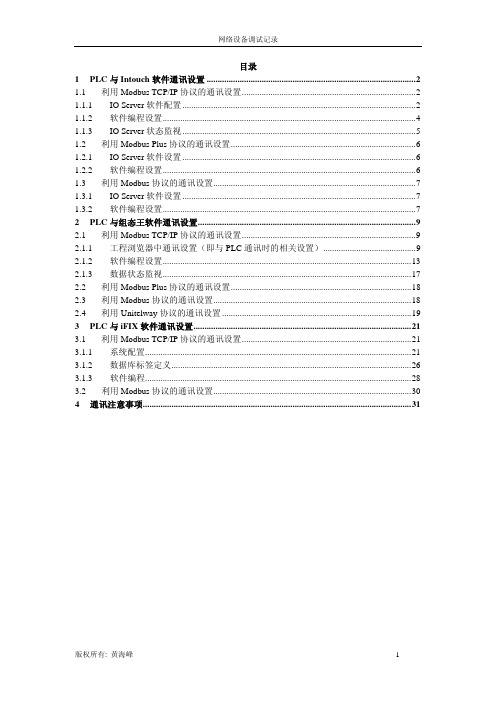
目录1PLC与Intouch软件通讯设置 (2)1.1 利用Modbus TCP/IP协议的通讯设置 (2)1.1.1 IOServer软件配置 (2)1.1.2 软件编程设置 (4)Server状态监视 (5)1.1.3 IO1.2 利用Modbus Plus协议的通讯设置 (6)Server软件设置 (6)1.2.1 IO1.2.2 软件编程设置 (6)1.3 利用Modbus协议的通讯设置 (7)Server软件设置 (7)1.3.1 IO1.3.2 软件编程设置 (7)2PLC与组态王软件通讯设置 (9)2.1 利用Modbus TCP/IP协议的通讯设置 (9)2.1.1 工程浏览器中通讯设置(即与PLC通讯时的相关设置) (9)2.1.2 软件编程设置 (13)2.1.3 数据状态监视 (17)2.2 利用Modbus Plus协议的通讯设置 (18)2.3 利用Modbus协议的通讯设置 (18)2.4 利用Unitelway协议的通讯设置 (19)3PLC与iFIX软件通讯设置 (21)3.1 利用Modbus TCP/IP协议的通讯设置 (21)3.1.1 系统配置 (21)3.1.2 数据库标签定义 (26)3.1.3 软件编程 (28)3.2 利用Modbus协议的通讯设置 (30)4通讯注意事项 (31)1 PLC与Intouch软件通讯设置Intouch软件中与施耐德PLC相关的驱动只有三种:Modbus TCP/IP、Modbus Plus、Modbus。
1.1 利用Modbus TCP/IP协议的通讯设置Server软件配置1.1.1 IO首先启动Intouch软件中的IOServer软件(软件与Intouch软件不同时提供,除非盗版):Modicon MODBUS Ethernet软件,见下图所示:IO Server软件选择画面Server配置软件启动后,点击Configure->Server Settings…菜单,见下图所示:在弹出对话框中主要设置两个参数:Protocol Timer Tick:该时间必须是最快刷新数据所需时间的2~4倍;Start automatically as Windows NT Service:如需系统启动后,该IO Server驱动自动运行时,可以选中。

如何配置Intouch SIDirect DAServer 通过TCP/IP和S7 PLC通信如何配置SIDirect DAServer 通过TCP/IP实现和S7 PLC的通信概要介绍无需借助西门子的Simaticnet 软件,SIDirect DAS Server 可以通过标准的以太网卡访问S7 200, S7 300,S7 400 家族PLC。
SIDirect DAServer可以通过DDE, FastDDE, SuiteLink, OPC协议连接Windows客户端软件,如Wonderware InTouch。
本Tech Note 一步一步详细介绍了如何配置和使用Wonderware SIDirect DA Server连接/访问S7 PLC(这里,我们以S7-400 PLC 为例),以及如何用DDE/SuiteLink协议访问此DA Server。
在开始之前,请确保已满足以下条件:1.仔细阅读并按照SIDirect DAServer的Readme文件及相关文档,来得到SIDirect DAServer所需要的系统需求,正确的安装过程,操作系统等信息。
2.安装SIDirect DAServer,如果已经安装了以前版本的SIDirect DAServer,请使用的"控制面板"中的"添加/删除程序"卸载,本Tech Note使用SIDirect DAServer 1.1版。
3.安装并配置以太网卡和TCP/IP协议。
4.确认你可以"Ping"通你要连接的PLC。
注意:请仔细阅读SIDirect DAServer的在线文档关于所支持的硬件和软件部分,SIDirect DAServer只支持TCP/IP 通信,不支持MPI,Profibus等其他非以太网方式。
本Tech Note假定用户具有并理解以太网,西门子S7 PLC 硬件/软件,Windows 操作系统,Wonderware FactorySuite组件,WWClinet, SIDirect DAServer的基本知识。

配置S7 DAServer通过MPI/Profibus实现和S7 PLC的通信文档号:LY-COMMUNICATION-003版本:1.0制作:2007年11月刘喜概要介绍本文档详细描述了DA 服务器程序(DASS7)与西门子S7300,S7400 家族PLC通过Simatic Net通信的组态步骤。
另外,在DASS7配置完成后,需要建立一个DDE/Suitelink的连接来确认配置是否正确。
开始之前在开始之前,请确保已满足以下条件:1.仔细阅读并按照S7SIMATIC DAServer 的Readme文件及相关文档,来得到S7SIMATIC DAServer所需要的系统需求,正确的安装过程,操作系统等信息。
2.安装S7SIMATIC DAServer,如果已经安装了以前版本的S7SIMATIC DAServer,请使用的"控制面板"中的"添加/删除程序"卸载,本Tech Note使用S7SIMATIC DAServer 1.5 Service Pack 1版。
3.安装并配置5611卡等MPI/Profibus通信协议卡。
4.安装SIMATIC Step V5.4 + SP3,Industrial Ethernet SOFTNET-S76.3软件提示:为了简化组态过程,本文例中均使用缺省设置,包括所有自动生成的命名。
这些名称可以通过(右击/重命名)的方式随时更改。
由于每套系统都是不同的,所以要尽量理解DASS7中的不同设置以优化组态。
第一步:配置Simatic Net 连接1.配置PC 站的硬件机架当SIMATIC NET 软件成功安装后,在PC 机桌面上可看到Station Configurator 的快捷图标,同时在任务栏(Taskbar)中也会有Station Configuration Editor 的图标。
1.1通过点击图标打开Station Configuration Editor 配置窗口。

Intouch与西门子S7-200/S7-300/S7-400的以太网通讯配置无需借助西门子的Simaticnet 软件,SIDirect DAS Server 可以通过标准的以太网卡访问S7 200, S7 300,S7 400 家族PLC。
SIDirect DAServer可以通过DDE, FastDDE, SuiteLink, OPC协议连接Windows客户端软件,如Wonderware InTouch。
注意:SIDirect DAServer只支持TCP/IP通信,不支持MPI,Profibus等其他非以太网方式。
这里以Intouch2014与西门子400的以太网冗余通讯为例,所需软件如下:Intouch2014要求采用SIDirect 3.0sp1版本的驱动,Intouch10.0/10.1等采用更低版本如1.5/2.0等。
配置SIDirect DAServer 步骤如下:1、开始菜单——所有程序——Wonderware——System Management Console,双击启动System Management Console程序;2、在ArchestrA System Management Console(SMC)中找到“DAServer Manager”,依次展开Default Group ——Local——ArchestrA.DASSIDirect.33、展开ArchestrA.DASSIDirect.3,并选择“Configuration”,将出现如下“Global Parameters”对话框:【参数一般默认不修改】◆Device Group Update Interval: 定义Device Group的默认更新时间间隔◆Slow Poll Interval: 定义当连接发生问题进入“Slow Poll”模式时,DAServer查询设备的时间间隔。
当通信恢复正常后,DAServer的查询间隔调整为Device Group的查询间隔。
AVEVA INTOUCH2020通过驱动OI SERVER 连接S7 300/400 PLC一系统环境 (2)二配置过程 (2)2.1SIEmens SIDIR驱动 (2)2.2Configuration 配置 (3)2.3PORT 端口设定1 (4)2.4Legacy connection 1 规则连接1 (5)2.5PORT 端口设定2 (6)2.6Legacy connection 2 规则连接2 (6)2.7REDUNDANT CONNECTION 冗余连接 (7)2.8REDUNDANT Device Groups Name 冗余设备名 (8)2.9Activate 激活OI SERVER驱动 (8)三INTOUCH访问连接 (9)3.1INTOUCH访问名配置 (9)3.2INTOUCH初始化I/O报错 (10)一系统环境序号说明安装软件上位机软件AVEVA INTOUCH 2020R2System_Platform_2020_R2.iso通讯驱动OI SERVER AVEVA CommunicationDrivers Pack 2020.3.iso※System Intouch 2020 R2仅支持Win10 64位操作系统(1803之前的Windows 10版本不支持)二配置过程首先安装驱动软件AVEVA Communication Drivers Pack 2020.3.iso 中的Siemens-SIDIRECT,安装完毕后在SMC中进行配置。
2.1 SIEMENS SIDIR驱动开始->AVEVA->System Platform Management Console(SMC),展开Operations Integration Server Manager并选择到Siemens-SIDIRECT->OI.SIDIR.1图例1 图例22.2 CONFIGURATION 配置展开OI.SIDIR.1 ->Configuration图例3Global Parameters 释义Device Group Update Interval:默认更新时间间隔!Slow Poll Interval: 定义当连接发生问题进入“Slow Poll”模式时,OI Server查询设备的时间间隔。
NetToPLCsim S7online VersionIntroductionThe old NetToPLCsim-Version used the S7ProSim-COM-Object to exchange data with Plcsim.The version described in this document uses the so called S7online interface. The old version had to dissect the S7-protocol and read/write data through the S7ProSim interface. The new version starts a IsoOnTCP server and forwards the payload into the S7online-interface.The main differences between 'old' and 'new' version:•Support of multiple clients (max. 100)•No limits in supported data areas, it's possible to read and write timer (T) and counter (C), read digital-inputs (I) and write digital-outputs (O)•Support of multiple Plcsim instances•Improved data throughput•Support of other PLC functions, like Run/Stop, timesystem, reading of SZL (maybe different to a 'real' PLC)To use this new version, you have to configure a PLC with a network interface, like a PN-CPU or a classis CPU with additional Ethernet CP.NetToPLCsim acts as intermediary between Plcsim and your real network interface.The service …SIMATIC IEPG Helper“As you have Step7 installed on your PC, then there is a Windows service called …SIMATIC IEPG Helper“ running in the background. This service holds TCP port 102 in use. But this port is used for S7-communication, so this service must be stopped before starting NetToPLCsim.At program start, NetToPLCsim checks if port 102 is free. If it's not, then it asks to stop the …SIMATIC IEPG Helper“ service.When you ended with testing with NetToPLCsim, it's recommended to restart the service before doing other work with SIMATIC software.Alternitavely you can stop the service with the following two little batch files:Stop IEPGhelper.bat:net stop s7oiehsxStart IEPGhelper.bat:net start s7oiehsxHintYou need administrative rights to make changes on the windows service control. On Windows XP your actual user account needs admin-rights, on Windows 7 you need to start NetToPlCsim with administrative rightsSimulation with one single Plcsim instanceExample configuration:S7-300 PN-CPU with IP-address:192.168.1.101LAN interface IP-address:192.168.1.101)Start PLCSIM out of the SIMATIC-Manager2)Set PG/PC interface in PLCSIM to 'PLCSIM(TCP/IP)'3)Load your PLC program including system data into PLCSIM 4)Start NetToPLCsim5)In NetToPlCsim add a new station6)Insert unique name in …Name“ field for this station7)In …Network IP Address“ field, insert the IP-address of your LAN interface, on which Plcsim should be reachable (e.g. 192.168.1.10). Clicking on (…) shows a new windows where all interface IP-addresses are listed.8)In …Plcsim IP Address“ field, insert the IP-address of your PLC (IP-address which is shown in Plcsim status bar). Clicking on (…) shows a new windows where all PLCSIM reachable PLCs are listed.9)Apply station configuration with OK10)A click on …Start all“ will start the serversWhen state changes to 'RUNNING', a client like SCADA/visualisation-systems can reach the Plcsim PLC on IP-address 192.168.1.10To stop the simulation, at the first step stop NetToPLCsim. At the second step stop PLCSIM.Simulation of multiple Plcsim-InstancesTo connect to multiple PLCSIM-simulations at the same time, NetToPLCsim needs a separate IP-address for each server to start on. It's possible to realize this with inserting more than one network interface card, or by simply adding additional IP-addresses to the existent interface.The image sequence above shows how to add additional IP-addresses to you LAN interface.(german Windows 7 version)HintTo avoid later network problems, you should delete the additional IP-addresses when finished with testing (my experience)A new PLCSIM instance can be started out of the first PLCSIM instance by menu File → …New Plc“ (or something like that, I've got only the german version).The following steps are equal to simulation with on PLCSIM instance.For the constellation shown in fig.2, the configuration shown in this image is needed:Monitoring of the data-exchangeWhen the nettoplcsim servers are started, the …Start monitoring“ entry in the context-menu of the station list is enabled. For each station a separate monitoring-windows can be started. In the monitoring-windows only the usually telegrams for data-exchange (Read/Write-Requests) between a PLC and a SCADA-system are shown.To debug more details of the protocol, you can use Wireshark with my s7comm plugin-dll./projects/s7commwiresharkNotice:The activated monitoring reduces the data exchange rate significant.Version history0.9.0–First version using the S7online interface0.9.1–added optional monitoring of the data exchange。
一、配置STEP7 Micro/win以太网12、点击下一步至如下画面:用PPI线通讯上后可读取以太网模块位置。
以太网模块直接在CPU后为位置0,本项目为03下一步设置IP地址4继续下一步,出现以下画面:配置TSAP地址,本项目PLC为服务器,以太网位置为0,所以本地为“10.00”,若以太网位置为1,则为“10.01”,以此类推。
远程TSAP与本地不同即可。
设好后点击确认。
4、确认后点击下一步出现以下画面,点击建议地址,PLC会自动分配地址。
点击下一步至完成。
到此,以太网设置完成。
将项目保存,用PPI线下进PLC。
插上网线,更改电脑IP地址,应可“ping”的通,设置STEP通信,将PLC IP地址填进远程,双击刷新后可找到PLC,至此,PC机与PLC连接上。
二、设置PC ACCESS1、设置之前,先点击保存,将项目保存起来。
2、新建PLC3、在新建的PLC下新建项目,项目即为上位机需要的变量,名称、注释可更改。
4项目建完后,点击上图属性,填进PLC的IP地址和TSAP地址,注意,此处的TSA地址顺序与设置PLC以太网时相反,即本地、远程要颠倒一下。
设置完后点击确定。
5、PC ACCESS带测试客户端,如下图,选中项目,点击红圈处,可将项目移至测试端,也可拖动。
再点击红圈处右边一个按钮,可打开测试端,如PC ACCESS与PLC通讯正常,显示“好”,如下图所示:至此,PC ACCESS设置完毕。
三、intouch OPC fsgateway设置1,装好fsgateway,打开SMC,点击下图阴影位置,将fsgateway激活(打对勾为激活)。
2、点击下图阴影位置,添加OPC Object3、添加好后,出现下图,设置OPC:server node 如PC ACCESS与本软件在同一计算机上运行,server node为:localhost;点击server name右侧浏览按钮,会自动搜索到PC ACCESS 的服务器名称,选中后保存。
Configuring Simatic Net PC Software V6.1 SP1 for s7 I/O Server to Access S7 PLC Via CP5611
要求:需安装Simatic NCM PC/S7 v5.1 SP2 或STEP7 V5.1 SP2
操作系统:Win2000 + SP3
一、安装
1、安装Simatic Net PC Software V6.1, Simatic NCM PC/S7 或STEP 7。
2、关机,安装CP5613卡。
二、配置Simatic Net
1、开机,系统启动后,Simatic Net 自动搜索本机的西门子资源,并启动
Commiong Wizard。
点击Next,进入下一步
如上图配置通讯卡,其中Station adderss 不能与Profibus上的地址冲突,Transmission rate 和Bus profile 必须和PLC中的设定一样。
点击Next,进入下一步,若系统中有网卡,则会如下图
如图选择, 点击Next,进入下一步。
如图配置,增加一个application, 也就是将要用到的Wonderware S7 I/O Server。
点击Next,进入下一步。
如图配置,点击Next进入下一步。
点击Next,进入下一步。
点击“确定”。
2、建立本机application 和PLC 的S7 协议的连接(需要通讯的每一个PLC
都要建立一个连接)
1)点击上图PC Station Wizard,弹出如下图对话框。
点击OK。
2)如图选择,点击“下一步”。
3)如图选择,点击“完成”。
左下栏会显示连接表(connection table)。
5)在表中选择一条空栏,打开右键菜单
6)如图选择,点击OK继续。
上图中,Local ID 一项用户可以自定义,Partner 一栏下的Address项为PLC的Prifibus地址。
7)点击Address Details。
上图中,Rack项是PLC的CPU模块所在的背板号,Slot项是PLC的CPU模块所在的槽位号。
8)点击OK继续。
9)点击“确定”继续。
10)重复步骤5)~9),建立本机和其他PLC的S7协议连接。
11)上图中点击工具栏中的Save and Compile 工具(图中箭头所指), 将完成的配置编
译并保存。
12)点击OK继续。
11)下图中,点击选择TWD一栏。
点击工具栏中的download工具(图中箭头所指)将配置下装到本机。
12)退出。
返回Commissioning Wizard 窗口。
13) 点击Next 继续。
14) 点击Next 继续。
15)点击Finish 继续。
3、安排访问点(Access Point)。
如上图,鼠标左健双击CP_l2_1: 一栏。
在Associated interface parameter assignment 一栏,选择CP5611(PROFEIBUS),如图。
点击“确定”继续
退出。
4、检查Station configuration Editor(屏幕右下角工具栏中)中显示的状态正
确。
5、配置S7 I/O Server。
如下图启动S7 I/O Server。
如图,打开定义Topic 对话框。
点击New 继续。
Topic 一项任意输入Topic名字,例:plc。
CP-Name 选择Commissiong Wizard 中定义的访问点,CP_L2_1:
VFD一项,选择S7连接中定义的VFD name : Application。
connection 一项,选择S7连接中定义的Local ID : S7_connection_1。
Optimization 一项,选择S7 SAPI。
点击OK 继续。