丹佛斯电动调节阀特性
- 格式:docx
- 大小:19.11 KB
- 文档页数:2
丹佛斯电动调节阀1. 简介丹佛斯电动调节阀是一种用于控制流体介质的设备,采用电动执行机构作为驱动力源,以实现精确的流量调节和流体控制。
该调节阀具有调节精度高、响应速度快、可远程操作等特点,广泛应用于各行各业的工业自动化控制系统中。
2. 结构与原理2.1 结构丹佛斯电动调节阀的主要组成部分包括阀体、阀座、活塞、电动执行机构等。
•阀体:通常采用优质铸铁或不锈钢材料制成,具有良好的耐腐蚀性和密封性能。
•阀座:位于阀体内部,通过调节阀座的开度来控制流体的流量。
•活塞:负责连接阀芯和电动执行器,调节阀芯的位置和开度。
•电动执行机构:由电机和传动装置组成,通过控制电机的正反转来实现阀芯的升降,从而调节阀的开度。
2.2 原理丹佛斯电动调节阀的工作原理基于反馈控制系统。
当控制系统发送控制信号时,电动执行机构根据信号的输入来调节阀芯的位置,从而改变阀座的开度,进而调节流体的流量。
同时,通过传感器获取流体的参数,并将反馈信号发送给控制系统进行实时监测和调整,以保证流体的稳定控制。
3. 特点与优势3.1 调节精度高丹佛斯电动调节阀采用先进的控制算法和精密的执行机构,具有极高的调节精度,能够实现精确到百分之一的流量控制。
3.2 响应速度快电动执行机构具有快速响应的特点,能够在短时间内完成阀芯的升降,实现快速调节和控制。
3.3 远程操作与监控丹佛斯电动调节阀支持远程操作与监控,通过与控制系统的连接,实现远程控制和参数监测,提高了操作的便捷性和效率。
3.4 可编程性强该电动调节阀具备良好的可编程性,用户可以根据实际需求自定义控制策略和参数,以适应不同的工业流程要求。
3.5 耐腐蚀性好丹佛斯电动调节阀采用优质的阀体材料,具有良好的耐腐蚀性,可以适应多种流体介质的控制需求。
4. 应用领域丹佛斯电动调节阀广泛应用于以下领域:•石油化工:用于炼油、化工生产中的流体控制和调节。
•电力行业:用于电厂锅炉的水位控制和调节。
•冶金行业:用于冶金过程中炉温的控制和调节。
调节阀的4种流量特性
1正逆行阀特性
正逆行阀特性是调节阀中最常见的流量特性,即调节阀的阀板由可调座在正、反两个方位转换。
随着阀板的移动,流量的增减空间是不断在正反之间变化的,最终达到设定的流量值。
正逆行阀的优势是,抗压力能力高,密封性好,动作健壮,结构简单,噪音小,前后行程最大化,但精度低,斜度梯形典型,处理流量噪音变化较大。
2双调节特性
双调节特性是指调节阀内部有两个独立行程空间,根据需要可以任意调节,从而让阀板呈现一个平滑的斜列面,流量曲线是多项式拟合的。
双调节特性的优势是控制的动作精度高,具有优异的空载性能和可控制性,流量响应迅速精准,过程变化具有很好的稳定性,但处理能力不足。
3耦合形态特性
耦合形态特性是指流量及阀板间运动耦合关系,结合正反行程和双调节空间特性,使流量曲线看起来像是拉扯。
耦合形态特性的优势是控制变比更大、流量控制可控性和稳定性更好以及噪音控制更出色,但回归特性较差。
4多阶梯形特性
多阶梯形特性是最复杂的阀板的移动特性,它是不同的阶梯组合在一起,通过多段流量曲线改善流量响应。
多阶梯形特性的优势是具有良好的抗压能力、可适应高温高压的环境,可实现优化的流量控制,控制响应快,精准,但设计和生产难度大,价格略高。
以上就是调节阀的4种流量特性,不同特性有着不同的优势和缺点,可以根据实际需要选择不同的流量特性来满足用户的需要。
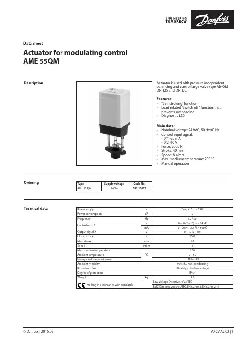
© Danfoss | 2016.09VD.CV.A2.02 | 1Actuator for modulating control AME 55QMData sheetActuator is used with pressure independent balancing and control large valve type AB-QM DN 125 and DN 150.Features:• “Self stroking” function• Load related “Switch off“ function that prevents overloading • Diagnostic LEDMain data:• Nominal voltage: 24 VAC, 50 Hz/60 Hz • Control input signal: - 0(4)-20 mA - 0(2)-10 V • Force: 2000 N • Stroke: 40 mm • Speed: 8 s/mm• Max. medium temperature: 200 °C • Manual operationDescriptionOrderingType Supply voltageCode No.AME 55 QM24 V~082H3078Technical dataPower supply V 24~; +10 to – 15%Power consumption VA 9Frequency Hz 50 / 60Control input Y V 0 – 10 (2 – 10) Ri = 24 kΩmA 0 – 20 (4 – 20) Ri = 500 ΩOutput signal X V 0 – 10 (2 – 10)Close of force N 2000Max. stroke mm 40Speeds/mm 8Max. medium temperature °C200Ambient temperature 0 – 55Storage and transport temp. –40 to +70Ambient humidity 95% r.h., non-condensing Protection class III safety extra-low voltageDegree of protection IP 54Weight kg 3.8- marking in accordance with standardsLow Voltage Directive 73/23/EECEMC-Directive 2006/95/EEC, EN 60730-1, EN 60730-2-14Data sheet Actuator for modulating control AME 55 QM2 | © Danfoss | 2016.09VD.CV.A2.02Installation MechanicalThe actuator should be mounted with the valvestem in either horizontal position or pointingupwards. Use a 4 mm Allen key (not supplied) tofit the actuator to the valve body.Allow for necessary clearance for maintenancepurposes.The valve has position indication ringswhich should be pushed together beforecommissioning; after stroking they indicate theends of the stroke.ElectricalElectrical connections can be accessed byremoving the cover. Two M16 × 1.5 cable entriesare provided. Both entries are provided with arubber grommet for use with flexible cable. Notethat in order to maintain the enclosure IP rating,appropriate cable glands must be used.Wiring The actuator must be dismantled and the elements sorted into various material groups before disposal.Disposal 24 Vac only.Wiring length Recommendedsquare of the wiring0-50 m0.75 mm2> 50 m 1.5 mm2Automatic self stroking featureWhen power is first applied, the actuator willautomatically adjust to the length of the valvestroke. Subsequently, the self stroking featurecan be re-initialised by changing position of SW9.Diagnostic LEDThe red diagnostic LED is located on the pcbunder the cover. It provides indication of threeoperational states:• Actuator Healthy (Permanently ON),• Self Stroking (Flashes once per second),• Error (Flashes 3 times per second - seektechnical assistance).Data sheetActuator for modulating control AME 55 QM© Danfoss | 2016.09 | 3VD.CV.A2.02DIP switch settingThe actuator has a function selection DIP switch under the removable cover. In particular, if SW6 is set to ON, the actuator will perform as 3-point actuator.The switch provides the following functions:• SW1: U/I - Input signal type selector:If set to OFF position, voltage input is selected. If set to ON position, current input is selected.• SW2: 0/2 - Input signal range selector:If set to OFF position, the input signal is in the range from 2 V to 10 V (voltage input)or from 4 mA to 20 mA (current input). If set to ON position, the input signal is in the range from 0 V to 10 V (voltage input) or from 0 mA to 20 mA (current input).• SW3: D/I - Direct or inverse acting selector:If set to OFF position, the actuator is direct acting (stem contracts as voltage increases). If actuator is set to ON position the actuator is inverse acting (stem extracts as voltage increases).• SW4: —/Seq - Normal or sequential modeselector:If set to OFF position, the actuator is working in range 0(2)..10V or 0(4)..20mA. If set to ON position, the actuator is working in sequential range; 0(2)..5 (6)V or (0(4)..10 (12)mA) or (5(6)..10V) or (10(12)..20mA).• SW5: 0..5V/5...10V - Input signal range insequential mode:If set to OFF position, the actuator is working in sequential range 0(2)..5 (6)V or 0(4)..10 (12)mA. If set to ON position, the actuator is working in sequential range; 5(6)..10V or 10(12)..20mA.• SW6: Prop./3-pnt - Modulating or 3-point modeselector:If set to OFF position, the actuator is working normally according to control signal. If set to ON position, the actuator is working as 3-point actuator.For this operation please refer to page 2(wiring 3-point control).When DIP switch SW6 is set to ON than allfunctions from other DIP switch become inactive.• SW7: LOG/LIN - Equal percentage or linear flowthrough valve selector:If set to OFF position, the flow through valve is equal percentage. If set to ON position, the flow through valve is linear according to control signal.• SW8: 100% K VS/Reduced K VS :To be set to OFF position (no sense in combination with AB-QM).• SW9: Reset:Changing this switch position will cause the actuator to go through a self stroking cycle.Complete the mechanical and electricalinstallation and perform the necessary checks and tests:• Isolate control medium. (e.g. self stroking in a steam application without suitable mechanical isolation could cause a hazard).• Apply the power. Note that the actuator will now perform the self stroking function.• Apply the appropriate control signal and check the valve stem direction is correct for the application.• Ensure that the actuator drives the valve over its full stroke, by applying the appropriate control signal. This action will set the valve stroke length.The unit is now fully commissioned.CommissioningCommissioning / testing featureThe actuator can be driven to the fully open or closed positions (depending on valve type) by connecting SN to terminals 1 or 3.VD.CV.A2.024 | © Danfoss | DHS-SRMT/SI | 2016.09Data sheetActuator for modulating control AME 55 QMActuator - valve combinationsThe manual override is applied by rotating the 4 mm Allen key (not supplied) to the required position. Observe the direction of the rotation symbol.• Disconnect power supply• Adjust valve position using an Allen key • Set valve to closed position •Restore power supplyIf manual override has been used then X and Y signal are not correct until the actuator reaches its end position. If this is not accepted reset the actuator, or apply accessory active return signal kit.DimensionsManual override。
制冷剂适用于各种不可燃的制冷剂,包括R717,和无腐蚀性气体/液体介质,但需注意使用相应的密封材料。
不推荐此阀使用于可燃的碳氢化合物。
此阀只推荐使用于闭式循环中。
若需了解更多详细信息,请联系Danfoss。
温度范围REG: –50/+150°C (–58/+302°F)REG-SS: –60/+150°C (–76/+302°F)压力范围最大的工作压力:40 bar g (580 psi g)安装介绍在安装此阀时,必须将调节杆竖直向上或水平放置 (fig. 1)。
应按照安装指导说明手工开阀。
此阀的设计可以使其能够承受其内部的高压,但是,设计管路系统时应该避免带液,以减少由于热力膨胀而引发的液击的风险。
必须保证此阀在系统短暂液击时得到保护。
流体流向推荐阀体上有箭头指示流体流动的方向,直接指向阀芯。
关闭和开启阀门所需的力必须不能超过正常用手轮开启时的力。
焊接在焊接之前必须拧掉阀帽(bonnet)(fig. 3),以避免填料函和阀体与阀帽(bonnet)之间的O型圈受到损伤,同时也能保护阀座中的特氟龙垫片。
根据阀体的材料选择合适的焊接材料和焊接方法。
焊接完后,在阀组装前应该清理阀内部的焊渣与废屑。
而且需保证阀体和阀帽(bonnet)的螺纹中没有焊渣及脏物。
假如有如下几种情况,可以不必取下阀帽(bonnet):焊接时阀体与阀帽(bonnet)温度没有超过+150°C/+302°F。
这个温度的高低取决于焊接的方法及焊接时阀体上的冷却方法。
(冷却方法,比如用一个湿布包住阀体等。
) 在焊接的过程中,必须确保没有焊渣及脏物进入阀内。
必须谨慎不能破坏特氟龙密封。
安装之后阀体不能承受外部压力。
在系统中REG阀的出口不能与大气连通。
阀的出口侧必须连接在系统中或者用封帽盖上,例如用一个焊接端盖。
装配在装配之前必须清除管道及阀体种地焊渣及脏物。
锥形阀芯在装入阀体之前检查其与阀帽(bonnet)是否之间是否拧紧(fig. 4)。

丹佛斯公司及产品简介丹佛斯公司是丹麦最大的工业产品生产企业,成立于1933年,在1943年丹佛斯发明了世界上第一个散热器恒温阀,并与1952年进行批量生产和销售,是世界上唯一的一家所有温控阀部件都自己生产的公司。
迄今为止,丹佛斯在全球销售了超过4亿套温控阀,稳居世界第一的宝座。
丹佛斯还生产换热器、换热机组、换热站控制原件、水力平衡阀、热表、地暖系统用分集水器和温控等,是世界上最大的供热产品生产企业,也是第一家进入中国推广分户计量的企业。
1996年,丹佛斯公司在天津武清开发区成立独资工厂,从丹麦引进生产线,并进口零部件在国内组装温控阀。
目前在武清工厂的投资超过10亿元人民币。
丹佛斯公司的目标是把中国建立为除丹麦的第二家乡市场。
丹佛斯散热器温控阀的特点:1.约70年的生产历史,生产设备先进,技术精湛,使用寿命长。
中国第一只温控阀由丹佛斯提供,1985年安装在北京燕沙中心。
2.所有部件坚持自己生产,并且每只温控阀在出厂前都经过多到工序的检验,保证了交给客户的每个温控阀都是质量合格的产品。
3.是世界上唯一具有能力生产气体温包的厂家,产品反应更灵敏,更加节能。
4.丹佛斯温控阀阀头获得了世界能效标识A级认定5.丹佛斯温控阀具有适用于双管系统的高阻力RA-N,RA-FN系列产品,也有适用于单管跨越系统的低阻力RA-G系列产品,应用广泛。
6.阀体为全铜材质,具有活接结构,活接连接处为金属硬密封,永不渗漏。
7.温控阀为双密封结构,可以带水带压更换阀芯,或进行清堵操作。
丹佛斯分户温控产品的特点:1.专用低阻力阀体,流通能力大,带来更小的阻力损失,对系统改造影响小。
2.阀体为全铜材质,具有活接结构,活接连接处为金属硬密封,永不渗漏。
3.阀体为双密封结构,可以带水带压更换阀芯,或进行清堵操作。
4.热电驱动器与阀体的连接采用卡式连接,定位准确,避免的人为误操作因素。
5.驱动器具有常开和常闭两种类型,供电有24V和220V两种类型。

调节阀及其流量特性介绍调节阀用于调节介质的流量、压力和液位。
根据调节部位信号,自动控制阀门的开度,从而达到介质流量、压力和液位的调节。
调节阀分电动调节阀、气动调节阀和液动调节阀等。
本手册主要介绍电动调节阀和气动调节阀两种。
调节阀由电动执行机构或气动执行机构和调节阀两部分组成。
调节并通常分为直通单座式和直通双座式两种,后者具有流通能力大、不平衡办小和操作稳定的特点,所以通常特别适用于大流量、高压降和泄漏少的场合。
流通能力Cv是选择调节阀的主要参数之一,调节阀的流通能力的定义为:当调节阀全开时,阀两端压差为0.1MPa,流体密度为1g/cm3时,每小时流径调节阀的流量数,称为流通能力,也称流量系数,以Cv表示,单位为t/h,液体的Cv值按下式计算。
根据流通能力Cv值大小查表,就可以确定调节阀的公称通径DN。
调节阀的流量特性,是在阀两端压差保持恒定的条件下,介质流经调节阀的相对流量与它的开度之间关系。
调节阀的流量特性有线性特性,等百分比特性及抛物线特性三种。
三种注量特性的意义如下:(1)等百分比特性(对数)等百分比特性的相对行程和相对流量不成直线关系,在行程的每一点上单位行程变化所引起的流量的变化与此点的流量成正比,流量变化的百分比是相等的。
所以它的优点是流量小时,流量变化小,流量大时,则流量变化大,也就是在不同开度上,具有相同的调节精度。
(2)线性特性(线性)线性特性的相对行程和相对流量成直线关系。
单位行程的变化所引起的流量变化是不变的。
流量大时,流量相对值变化小,流量小时,则流量相对值变化大。
(3)抛物线特性流量按行程的二方成比例变化,大体具有线性和等百分比特性的中间特性。
从上述三种特性的分析可以看出,就其调节性能上讲,以等百分比特性为最优,其调节稳定,调节性能好。
而抛物线特性又比线性特性的调节性能好,可根据使用场合的要求不同,挑选其中任何一种流量特性.等百分比特性(对数)等百分比特性的相对行程和相对流量不成直线关系,在行程的每一点上单位行程变化所引起的流量的变化与此点的流量成正比,流量变化的百分比是相等的。
3VF6000 Series Butterfly Valve and ActuatorVF6000 Series butterfly valve and VA300 actuator are designed to shutoff or regulate the flow of hot or chilled water in Heating, Ventilation and Air Conditioning (HVAC) system. This series covers models from DN50 to DN600 with either on/off or modulating output via various actuators.Actuators and valves are calibrated in the factory and are packed separately for ease of delivery and installation.Features and BenefitsOptions of Valve and ActuatorFigure 1.VF6000 Series Butterfly Valve and Actuator*Please refer to page 11 for the detailed valve and actuator combinationModel SelectionTable 1: VF6000 Series ValveTable 1: Ordering data of VF6000 Series Butterfly Valve and ActuatorTable 2: VA300 Series Actuators4SpecificationTable 3: VA300 Actuator performance summary56Table 4: Valve performanceInstallationMechanical InstallationElectric Wiring (VA300)NOTE: Ensure that the pipeline and flange faces are clean. Pipescale, metal chips, welding slag, and welding rods can obstruct disc movement and damage the disc and seat.NOTE: Wiring must be conducted by qualified technical staff.Read Installation Manual before wiring.WARNING: Risk of Electrical Shock. Disconnect the powersupply before making electrical connections. Contact with components carrying hazardous voltage can cause electrical shock and may result in severe personal injury or deathFor IP67 actuator wiring:6~12mm cable for type VA301.. 10~14mm cable for type VA302~VA310..Remove the protective cover by the screws on thecoverConduct the terminal wiring according to theinstallation manualCheck wiring again and power onTrail run the actuator and check the operationdirection and limiterPut on the protective cover again7Valve Dimension and WeightFigure 2. Valve DimensionTable 5: Valve dimension (mm) and weight (kg)VA300 Actuator Dimension02BDCN型89M9000-618-C Dimension10Table 6: Actuator Dimension*: Only On/Off Model available, no hand wheel for Model 01. Manual On/Off by using 8” wrench. Hand wheel is available for other Models of both On/Off and Modulating Control.Wiring DiagramFigure 4. Wiring diagram for On/off Actuator (Model Ended with BDC)Figure 5. Wiring diagram for Modulating Actuator (Model Ended with CDC)Figure 6. Signal Switch Over directionI/O Signal Switch OverDEFAULTControl Board Chart (Signal Switch Over Position)AC220V AC220V Input (Default)4-20mA ControlOutput (Default)4-20mA Feed back4-20mAOutput Load=250Ω4-20mAInput Resistor=250ΩN LGG123456I+I-O+O-G r o u n d i n gG r o u n d i n gI n p u t C u r r e n tV a l v e P o s i t i o n F e e d b a c k O p e S h u O p e n i n g E n C l o s i n g E n 1K P o s i t i o n F e e d b a c k P o t e n t i o m e n t e NLO p e n i n g E n d S w i t c C l o s i n g E n d S w i t cUser wiring (dashed)VF6000 Valve and VA300 Actuator match table Table7: On/Off Type SummaryTable8: Modulating Type Summary11Printed on recycled paper© 2013 Johnson Controls, Inc.PUBL-XXXX(XXXX)Johnson Controls is a global diversified technology and industrial leader serving customers in morethan 150 countries. Our 168,000 employees create quality products, services and solutions to optimize energy and operational efficiencies of buildings; lead-acid automotive batteries and advanced batteries for hybrid and electric vehicles; and interior systems for automobiles. Our commitment to sustainability dates back to our roots in 1885, with the invention of the first electric room thermostat. Through our growth strategies and by increasing market share we are committed to delivering value to shareholders and making our customers successful. In 2013, Corporate Responsibility Magazine recognized Johnson Controls as the #14 company in its annual “100 Best Corporate Citizens” list. For additional information,please visit .Johnson Controls Building Efficiency delivers products, services and solutions that increaseenergy efficiency and lower operating costs in buildings for more than one million customers. Operating from 500 branch offices in more than 150 countries, we are a leading provider of equipment, controls and services for heating, ventilating, air-conditioning, refrigeration and security systems. We have been involved in more than 500 renewable energy projects including solar, wind and geothermal technologies.Our solutions have reduced carbon dioxide emissions by 16 million metric tons and generated savings of $7.5 billion since 2000. Many of the world’s largest companies rely on us to manage 1.8 billion square feet of their commercial real estate.Asia Engineering Centre: Wuxi, ChinaShanghai Distribution Center: Shanghai, ChinaAsia Centre of Excellence in Engineering (CoEE): Beijing, China · Mumbai & Pune, India Manufacturing/Assembly: Guangzhou & Wuxi, China · Pune, IndiaThailandTel : +66 (2) 717 1260-80Fax: +66 (2) 717 0861MalaysiaTel : +60 (3) 7628 4393Fax: +60 (3) 7620 0538IndonesiaTel : +62 (21) 5366 8500Fax: +62 (21) 5366 8300AustraliaTel : +61 (2) 9805 8300Fax: +61 (2) 9889 3016New ZealandTel : +64 (9) 444 6434Fax: +64 (9) 444 2092JapanTel : +81 (3) 5738 6100Fax: +81 (3) 5738 6298China (Shanghai)Tel : +86 (21) 6276 6509Fax: +86 (21) 6277 3543SingaporeTel : +65 6748 0202Fax: +65 6284 3017KoreaTel : +82 (2) 554 5935Fax: +82 (2) 554 5739Hong KongTel : +852 2590 0012Fax: +852 2516 5648MacauTel : +853 2875 1820Fax: +853 2875 1825IndiaTel : +91 (22) 3082 2200Fax: +91 (22) 3088 1592Information contained herein including but not limited to the product design, specification or appearance is subject to change without notice. This document is for reference only, please refer to the actual product when buying.PUBL-6783(0613)。
调节阀的特性及选择调节阀是一种在空调控制系统中常见的调节设备,分为两通调节阀和三通调节阀两种。
调节阀可以和电动执行机构组成电动调节阀,或者和气动执行机构组成气动调节阀。
电动或气动调节阀安装在工艺管道上直接与被调介质相接触,具有调节、切断和分配 流体的作用,因此它的性能好坏将直接影响自动控制系统的控制质量。
本文仅限于讨论在空调控制系统中常用的两通调节阀的特性和选择,暂不涉及三通调 节阀。
1调节阀工作原理从流体力学的观点看,调节阀是一个局部阻力可以变化的节流元件。
对不可压缩的流 体,由伯努利方程可推导出调节阀的流量方程式为2 D 2式中:Q ――流体流经阀的流量, m/s ;p i 、p 2——进口端和出口端的压力, MPa2A ――阀所连接管道的截面面积, m ;D ---- 阀的公称通径,mm.3P ----- 流体的密度, kg/m ; z ――阀的阻力系数。
可见当A 一定,(P 1-P 2)不变时,则流量仅随阻力系数变化。
阻力系数主要与流通面积(即 阀的开度)有关,也与流体的性质和流动状态有关。
调节阀阻力系数的变化是通过阀芯行程 的改变来实现的,即改变阀门开度,也就改变了阻力系数,从而达到调节流量的目的。
得越大,Z 将越小,则通过的流量将越大。
2 •调节阀的流量特性调节阀的流量特性是指流过调节阀的流体相对流量与调节阀相对开度之间的关系,即Q Q max式中:Q/Q ax ―—相对流量,即调节阀在某一开度的流量与最大流量之比;I/L ――相对开度,即调节阀某一开度的行程与全开时行程之比。
一般说来,改变调节阀的阀芯与阀座之间的节流面积, 便可控制流量。
但实际上由于各种因素的影响,在节流面积变化的同时,还会引起阀前后压差的变化,从而使流量也发生变化。
为了便于分析,先假定阀前后压差固定,然后再引申到实际情况。
因此,流量特性有理 想流量特性和工作流量特性之分。
2.1调节阀的理想流量特性调节阀在阀前后压差不变的情况下的流量特性为调节阀的理想流量特性。
丹佛斯-AKS41-ICAD-EKC347电动阀使用说明书丹佛斯 AKS41 ICAD EKC347电动阀使用说明书本系统采用Danfoss的一套组合(AKS41液位传感器+(ICM+ICAD封闭式电动阀)+EKC347控制器)进行供液控制。
EKC347控制器可以根据AKS41液位传感器提供的4~20mA液位信号来精确控制ICM封闭式电动阀的开度。
以下分别给出AKS41液位传感器、ICAD电动阀马达(电动阀)、EKC347控制器的中文操作指南,如果与英文操作指南有冲突,以英文为准。
一、AKS41液位传感器、ICAD电动阀马达、EKC347控制器的初始设定AKS41液位传感器、ICAD电动阀马达、EKC347控制器必须进行初始设定。
1.1、液位控制器EKC347的设定设定●上电几秒,待显示0.00后,才允许开始设定;●同时按住两按钮,进入液位设定状态,显示值会不断闪动,按上下键调定设定值,设定完后再同时按住两键进行确认;●接着上步操作,按住上面的按键不放几秒钟后,可找到其它设置项r06、r12等进行设置;●待所有参数均设定完毕后,放开所有按键,一段时间后,显示自动恢复到原始画面。
注意:显示r12等设定项后,同时按住两键进入参数设定状态,通过按上下两键调定具体设定值,参数值设定完毕后,务必再次同时按住两键进行确认。
LED显示:当前实际液位值,按一下“下按键”,则LED显示为电动阀开度。
具体设定值参见以下表格:1.2、电动阀ICAD马达初始设定●按住中间的○按键几秒钟后,按▲▼键找到i10项,按下○键进入密码输入状态,再通过▲▼键找到密码值(密码为11),然后再按一下○键进行确认;●输入密码后便可以对参数进行设定了,按▲▼键找到需要设定的项,然后按○键,进入参数设定状态,通过按▲▼键设定参数值,参数设定完后,再按一下○键进行确认;设定完后电动阀会进行自动调节,发出嗡嗡的震动,且显示100%,说明设定正确。
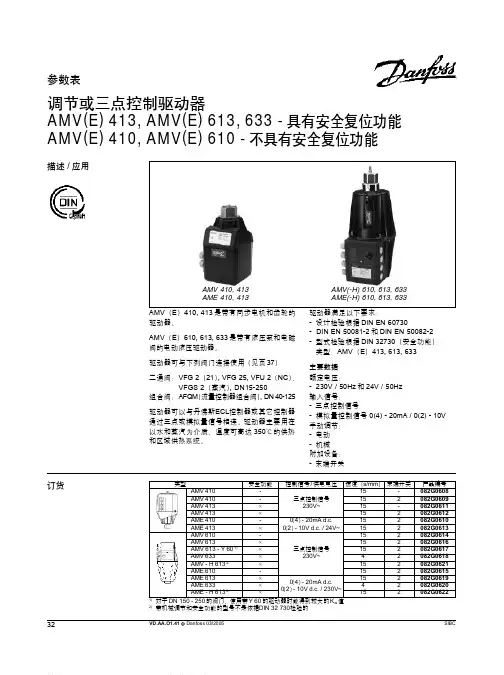
电动调节阀
功能描述:
阀门驱动器接受楼宇自动系统的信号,驱动阀锥改变阀门的开度,从而改变通过阀门的流量。
该阀门为调节型阀门,水流相对于阀芯的流向为低进高出型。
技术要求:
阀体性能
调节阀阀体结构为直行程的单座阀体,压力等级PN16,其流通能力(Kvs值)及口径必须满足工艺流量的要求。
1.流量特性为等百分比特性
2.控制比≥100:1
3.泄漏率≤Kvs值的0.05%
4.最小关闭压差≥1.5bar
5.最高介质温度130℃
6.阀体:为常开阀体,保证驱动器损坏或被卸下时,供热不间断
驱动器
1.驱动器由双向伺服电机驱动,齿轮为金属齿轮;
2.内置力敏开关保证驱动器不过载;
3.驱动器开与关两个方向的运行速度相同,以便温度控制的稳定;
4.驱动器断电时应保持在原位,应有过载保护;
5.可机械手动操作;
6.可将信号分割控制,确保两个调节阀并联使用时,用同一信号实现两个阀门顺序
开启;
7.控制信号为标准的模拟量信号,0(2)-10V/0(4)-20mA可选;
8.可选择正/反向动作;
9.具有阀门行程自检功能,以减少调试时间
10.电源为24Vac,50Hz;
11.外壳防护等级IP54;
材质要求:
DN15-50
1.阀体:红铜 DN15-50;
2.阀轴:不锈钢
3.阀座:黄铜
4.密封:不应有石棉材料,采用EPDM(三元乙丙橡胶);
DN65-150
5.阀体:DN65-100 铸铁;DN125-150 球墨铸铁;
6.阀轴:不锈钢
7.阀座:DN65 黄铜;DN80-100红铜;DN125-150球墨铸铁;
1.密封:不应有石棉材料,采用EPDM(三元乙丙橡胶)或PTFE(聚四氟乙烯);。