GAF Physical_Testing_of_Thermoplastic_Polyolefin_Membranes_and_Seams
- 格式:pdf
- 大小:629.88 KB
- 文档页数:7

thermo fisher scientific的实验条件-回复Thermo Fisher Scientific是全球领先的科学仪器和实验室设备供应商之一。
该公司提供广泛的实验室解决方案,包括实验条件、技术和设备。
在本文中,我们将一步一步回答关于Thermo Fisher Scientific的实验条件的问题。
第一步:确定实验目的在进行任何实验之前,我们首先需要明确实验的目的。
实验目的可以涵盖各种不同的科学领域和实验类型。
例如,我们可能想要测试某种药物的有效性,研究细菌的生长速率,或者评估食品中的营养成分含量。
无论实验目的是什么,Thermo Fisher Scientific都提供了各种不同的实验条件来满足不同需求。
第二步:选择适当的实验条件一旦我们确定了实验目的,我们就可以选择适合的实验条件。
这些条件将根据实验和应用的不同而有所变化。
例如,如果我们正在进行细胞培养实验,我们可能需要为细胞提供适当的培养基、温度和湿度条件。
Thermo Fisher Scientific提供了各种不同类型的细胞培养培养基、CO2培养箱和恒温恒湿箱,以满足不同实验的需求。
第三步:配置实验设备选择适当的实验条件后,我们需要配置实验设备。
这通常涉及到选择和设置合适的实验仪器、设备和耗材。
Thermo Fisher Scientific提供了各种不同类型的实验设备,如实验室培养皿、离心机、PCR仪器等。
根据实验的要求,我们可以选择合适的设备来支持实验的进行。
第四步:准备和调配试剂和溶液在进行实验之前,我们需要准备和调配所需的试剂和溶液。
这可能涉及到测量和混合不同的化学品、试剂和溶液。
为了确保实验的准确性和一致性,我们需要遵循严格的实验操作规程。
Thermo Fisher Scientific提供了各种不同类型的试剂和溶液,以支持不同实验的需求。
此外,他们还提供了一系列实验操作指南和安全操作规程,帮助用户正确地准备和使用试剂和溶液。

ThermodynamicsThermal expansionThe water anomalyDETERMINE THE TEMPERATURE WHERE WATER REACHES ITS MAXIMUM DENSITYUE201030104/16 ALFBASIC PRINCIPLESWater is unlike most other materials in that up to a tem-perature of about 4°C it initially contracts and only starts expanding at higher temperatures. Since the density is inversely related to the volume of a mass, water thus reaches its maximum density at about 4°C.The experiment involves measuring the expansion of water in a vessel with a riser tube. The height h to which water rises up the tube is measured as a function of the water temperature ϑ. Neglecting the fact that the glass vessel also expands at higher temperatures, the total volume of the water in the vessel and in the tube is given by:()()ϑ⋅⋅π+=ϑh d V V 42(1)d : Internal diameter of tube, V 0: Volume of vesselIf the expansion of the vessel is taken into account, equation (1) becomes()()ϑ⋅⋅π+ϑ⋅α⋅+⋅=ϑh d V V 4)31(2(2) α = 3.3 10-6K -1: linear expansion coefficient of glassFig. 1: Vessel with riser tube for measuring the thermal ex-pansion of waterFig. 2: Experiment set-up for determining the temperature ofthe maximum density of waterLIST OF APPARATUS1 Apparatus for demonstrating theanomaly of water 1002889 (U14318)1 Magnetic stirrer 1002808 (U11876)1 Digital thermometer, single channel 1002793(U11817)1 K-type immersion sensor 1002804 (U11854)or1 Thermometer 1003013 (U16115)1 Plastic funnel, d= 50 mm 1003568 (U8634700) 1 Silicon tubing, 1 m, 6 mm 1002622 (U10146)1 Stand rod, 470 mm 1002934 (U15002)1 Clamp with jaw 1002829 (U13253)1 Stand base 150 mm 1002835 (U13270)1 Plastic trough 4000036 (T52006) Distilled water, crushed ice, table saltSET-UP∙First place the stirrers into the apparatus for demonstrating the water anomaly.∙Mount the riser tube onto the glass vessel and screw it on tight.∙Connect the immersion sensor to the digital ther-mometer, screw the GL screw cap with the small bore onto the threaded tube at the side and insert the immersion sensor.∙As an alternative, the experiment can be conducted by using a standard thermometer. To use such an instrument, slide the GL screw cap with the large bore over the thermometer and attach it to the threaded tube at the side.∙Connect the silicon tube to the hose clip and then to the funnel.∙Set up the stand rod in the stand base. Attach the jaw clamp to the stand rod.∙Suspend the funnel from the clamp.∙In order to fill the glass vessel, open the tap and let distilled water into the funnel till the water level has reached approximately the middle of the riser tube. ∙Remove any air bubbles by gently shaking the glass vessel.∙Close the tap, remove the tubing and pour the ex-cess water back into its bottle. EXPERIMENT PROCEDURE∙Set up the experiment as in Fig. 2.∙Prepare a mixture of crushed ice and table salt, and fill the plastic tub with this mixture.∙Place the tub on the magnetic stirrer.∙Place the apparatus in the trough as illustrated in Fig. 2.∙Use a marker pen to mark the water level in the riser pipe. Note the water level and the tempera-ture.∙Switch on the magnetic stirrer and set it to medium speed.∙Read off the water level h in the riser tube and plot it as a function of temperature ϑ on a graph.∙As soon as the temperature falls below 0.5°C, re-move the experiment apparatus from the trough in order to prevent the water from freezing. SAMPLE MEASUREMENTSTable 1: Level of water h in riser tube measured as a function of temperature ϑEVALUATIONFig. 3 shows the curve resulting from the values in Ta-ble 1. The water level h in the riser pipe at 0°C is estab-lished by extrapolation. With this data, we get h (0°C) = 44.7mm. Using Equation (3), we can now cal-culate the relative density of water.Fig. 3: Water level h as a function of temperature ϑWater density ρ is derived from equation (1) and (2) as follows:()()()()ϑ⋅⋅π+ϑ⋅α⋅+⋅︒⋅⋅π+=︒ρϑρh d V h d V 4)31(C 04C 02020 (3)The maximum value of this expression occurs whenϑ = 4°C (see Fig. 4).Fig. 4: R elative density of water as a function of tempera-ture ϑRESULTSThe volume of water decreases as the temperature rises from 0°C to 4°C. The volume of water only in-creases at temperatures above 4°C.Water attains its maximum density at approx. 4°C,。

Thermo-Calc系统在材料科学中的应用Thermo-Calc 系统在材料科学中的应用在近十年内,计算机模拟在材料科学与技术中的应用对于材料设计的定量化产生了革命性的影响,各种热力学和动力学模型的组合使得预测材料加工过程中材料的成份、结构及性质成为了可能。
在此背景下,一个通用的热力学/动力学数据库必将为多个传统上认为是不同的领域提供高品质的内部一致的数据。
现有的Thermo-Calc 和DICTRA 数据库系统是一套强大且精细的软件系统,简单易学同时可以用于计算各种热化学计算以及一些类型的动力学模拟。
Thermo-Calc 系统是由瑞典皇家工学院材料科学与工程系为主开发,它包括了欧共体热化学科学组(SGTE)共同研制的物质和溶液数据库、热力学计算系统 (Thermo-Calc)和热力学评估系统(Top)。
Thermo-Calc 有 Windows 版(TCW 和DOS 版 (TCC)两种版本,均包含有SGTE 屯物质数据库、SGTE 溶液数据库、FEBASE 铁基合金数据库等多个数据库,还包括了 600多个子程序模块。
Thermo-Calc 系统是建立于强大的Gibbs 能最小化基础之上、仅有的计算在一个非常复杂的多元不均匀系中有多于5个独立变量的任意相图断面的软件,也有计算很多其它类型图的工具,如CVD 沉积、Scheil-Gulliver 凝固模拟、Pourbaix 图、气体分压等。
Thermo-Calc 由多个功能模块组成,各模块间的关系如图所示。
1. SYS:系统模块。
用于Thermo Cal 软件各模块的交互转换、宏文件操作等。
2. PARROTS 数优化模块。
根据已有的实验结果或文献数据,建立统一的热力学模型及参数。
3. ED_EXP:PARROT 子模块。
用于编辑实验数据。
4. TDB:热力学数据库模块。
5. GES 吉布斯能量系统模块。
用于热力学模型、数据的处理。
除非使用者能提供新的热力学数据,否则不会用到此模块。

air pressure test,空气压力试验high-resolution mass spectroscope,高分辨质谱仪器high-resolution NMR spectrometer,高分辨核磁共振波谱仪high-resolution NMR spectroscope,高分辨率核工业磁共振波谱仪high resolution visible(HRV)image instrument,高分辨率图像hit,命中hoarfrost point,结霜点hoisting test,起吊试验holding action,保持作用holding current,吸持电流hollow-cathode atomizer,空心阴极原子化器hollow-cathode lamp,空心阴极灯holographic grating,全息光栅holographic SDRS,全息地震仪homeostasis,内稳态homogeneity spoiling pulse,均匀性突变脉冲homogeneous radiation thermometer,单色辐射温度计homonuclear lock signal,同核锁信号hopper scale,料斗秤horizontal balancing machine,卧式平衡机horizontal limeit,水平极限horizontal scanning,行扫描horizontal tail,水平翼horizontal visibility,水平能见度hose coupler,软管接头host computer,主计算机hot wire anemometer,热线风速表hot wire flow transducer[sensor],热线流量传感器hot-wire respiratory flow transducer[sensor],流量传感器hot-wire turbulence meter,热线湍流计housing,外壳housing limit temperature,外壳极限温度huge system,巨系统hum,交流声humicap,湿敏电容器hnmid air,湿空气humid heat test,湿热试验humidification,加湿humidifier,加湿器humidistat,恒湿箱air sleeve,air temperature,气温air-tight instrument,气密式仪器仪表air to close,气关air to open,气开airborne electromagnetic system;AEM system,航空电磁系统airborne flux-gate magnetometer,航空磁通门磁力仪airborne gamma radiometer,航空伽玛辐射仪airborne gamma spectrometer,航空伽玛能谱仪airborne infrared spectroradiometer,机载红外光谱辐射计airborne optical pumping magnetometer,航空光泵磁力仪airborne proton magnetometer,航空甚低频电磁系统airborne XBT,机载投弃式深温计airgun controller,气控制器airmeter,气流表alarm summery panel,报警汇总画面alarm unit,报警单元albedograph,反射计alcohol thermometer,酒精温度表algorithm,算法algorithmic language,算法语言alidade,照准仪alignment instrument,准线仪alkali flame ionization detector(AFID),碱焰离子化检测器alkaline error,碱误差alkalinity of seawater,海水碱度all-sky camera,全天空照相机bit-serial higgway,位串行信息公路bivane,black box,未知框black light filter,透过紫外线的滤光片black light lamp,紫外线照射装置blackbody,黑体blackbody chamber,黑体腔blackbody furnace,黑体炉bland test,空白试验balzed grating,闪耀光栅block,block check,块检验block diagram,block length,字块长度block transfer,块传递blood calcium ion transducer[sensor],血钙传感器blood carbon dioxide transducer[sensor],血液二氧化碳传感器blood chloried ion transducer[sensor],血氯传感器blood electrolyte transducer[sensor],血液电解质传感器blood flow transducer[sensor],血流传感器blood gas transducer[sensor],血气传感器blood-group immune transducer[sensor],免疫血型传感器blood oxygen transducer[sensor],血氧传感器blood PH transducer[sensor],血液PH传感器blood potassium ion transducer[sensor],血钾传感器blood-pressure transducer[sensor],血压传感器blood sodium ion transducer[sensor],血钠传感器blood-volume transducer[sensor],血容量传感器blower device,鼓风装置bluff body,阻流体Bode diagram,博德图body temperature transducer,体温传感器bolometer,bomb head tray,弹头托盘honded strain gauge,粘贴式应变计bonnet,上阀盖boomerang grab,自返式取样器boomerang gravity corer,自返式深海取样管booster,增强器bore(of liquid-in-glass thermometer),borehole acoustic television logger,超声电视测井仪borehole compensated sonic logger,补偿声波测井仪borehole gravimeter,井中重力仪borehloe gravimetry,井中重力测量borehole thermometer,井温仪bottorm echo,底面反射波bottom flange,下阀盖bottom-loading thermobalance,下皿式热天平bottom surface,底面Bouguer's law,伯格定律Bourdon pressure sensor,弹簧管压力检测元件Bourdon tube,Bourdon tube(pressure)gauge,弹簧管压力表box gauge,箱式验潮仪BP-scope,BP 型显示Bragg's equation,布拉格方程braking time,制动时间braking torque(of an integrating instrument),branch,分支branch cable,支线电缆breakdown voltage rating,绝缘强度breakpoint,断点breather,换气装置bremsstrahlung,韧致辐射bridge,桥接器bridge's balance range,电桥平衡范围bright field electron image,明场电子象bridge for measuring temperature,测温电桥bridge resistance,桥路电阻brightness,亮度Brinell hardness number,布氏硬度值Brinell hardnell penetrator,布氏硬度压头Brienll hardenss tester,布氏硬度计broadband LAN,定带局域网。
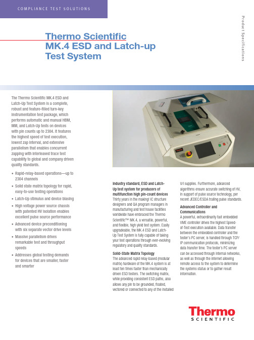
The Thermo Scientific MK.4 ESD and Latch-Up Test System is a complete,robust and feature-filled turn-key instrumentation test package, which performs automatic and manual HBM, MM, and Latch-Up tests on devices with pin counts up to 2304. It features the highest speed of test execution, lowest zap interval, and extensive parallelism that enables concurrent zapping with interleaved trace test capability to global and company driven quality standards.• Rapid-relay-based operations—up to 2304 channels• Solid state matrix topology for rapid, easy-to-use testing operations • Latch-Up stimulus and device biasing • High voltage power source chassis with patented HV isolation enables excellent pulse source performance • Advanced device preconditioning with six separate vector drive levels • Massive parallelism drives remarkable test and throughput speeds• Addresses global testing demands for devices that are smaller, faster and smarterThermo ScientificMK.4 ESD and Latch-up Test SystemIndustry standard, ESD and Latch-Up test system for producers ofmultifunction high pin-count devices Thirty years in the making! IC structure designers and QA program managers in manufacturing and test house facilities worldwide have embraced the Thermo Scientific™ MK.4, a versatile, powerful, and flexible, high yield test system. Easily upgradeable, the MK.4 ESD and Latch-Up Test System is fully capable of taking your test operations through ever-evolving regulatory and quality standards.Solid-State Matrix TopologyThe advanced rapid relay-based (modular matrix) hardware of the MK.4 system is at least ten times faster than mechanically driven ESD testers. The switching matrix, while providing consistent ESD paths, also allows any pin to be grounded, floated,vectored or connected to any of the installedV/I supplies. Furthermore, advancedalgorithms ensure accurate switching of HV, in support of pulse source technology, per recent JEDEC/ESDA trailing pulse standards.Advanced Controller and CommunicationsA powerful, extraordinarily fast embedded VME controller drives the highest Speed- of-Test execution available. Data transfer between the embedded controller and the tester’s PC server, is handled through TCP/IP communication protocols, minimizing data transfer time. The tester’s PC server can be accessed through internal networks, as well as through the internet allowing remote access to the system to determine the systems status or to gather result information.Product SpecificationsLatch-Up Stimulus and Device Biasing The MK.4 can be equipped with up to eight 100 V four-quadrant Voltage and Current (V/I) power supplies. Each V/I supply has a wide dynamic range enabling it to force and measure very low voltage at high current levels from 100 mV/10 A to 100 V/1 A. The system’s power supply matrix can deliver up to a total of 18A of current, which is distributed between the installed supplies. These supplies are able to provide a fast and versatile means of making DC parametric and leakage measurements as well as providing latch-up pulses, while offering total control and protection of the DUT.Advanced Device PreconditioningThe MK.4 system provides the most advanced device preconditioning capability available. The DUT can be vectored with complex vector patterns, providing excellent control over the device. Each pin can be driven using one of the 6 different vector supplies. The patterns can be up to 256k deep, running at clock speeds of up to 10 MHz. Device conditioning is easily verified, using the read back compare capability available on every pin.Thermo Scientific MK.4 Scimitar™Software Makes Programming Easy, while Providing Unsurpassed Programming FlexibilityThe MK.4 Windows®-based Scimitar operating software empowers users with the flexibility to easily set-up tests based on industry standards or company driven requirements.Device test plans can be created by importing existing text based device files, on the testers PC server or off-line from a satellite PC containing the application. The software also provides the capabilities to import test plans and device files from previous Thermo Scientific test systems.Test vectors from your functional testers can also be imported into the application. And of course, the vector application allows manual creation and debug of vector files.Device test plans and results are stored in an XML data base, providing unsurpassed results handling, sorting and data mining capabilities.Parallelism Drives Remarkable Test Throughput SpeedsThe MK.4 software enables ESD testing of up to twelve devices at one time using the multisite pulse source design.Embedded VME power supplies eliminate any communication delays that would be seen by using stand alone supplies. The embedded parametric (curve tracing) supply also provides fast, accurate curve tracing data to help you analyze your devices performance.The systems curve tracer can also be used as a failure analysis tool by allowing the comparison of stored, known good results, versus results from a new test sample or samples.Ready for Today’s Component Reliability Demands and Anticipating Those to Come ESD and Latch-Up testing of electronic and electrical goods can be very expensive aspects of the design and manufacturing process. This is especially true as market demands for products that are smaller, faster and smarter become the standard rather than the exception. The Thermo Scientific MK.4 leverages the technology and know- how gained over three decades of test system experience, as well as our in-depth participation and contributions to global regulatory bodies governing these changes, enabling today’s products to meet both global and industry-driven quality standards.The real key to our customers’ success is in anticipating what’s next. And to ensure that our customers possess the ability to evolve quickly to meet all change factors with efficiency and cost effectiveness.As such, the strategically-designed, field upgradeable architecture of the MK.4 system ensures a substantial return on investment over a very considerable test system lifecycle, as well as better short- and long-term qualityand ESD and Latch-Up test economies.Custom fixtures include universal package adaptors to enable the industry’s lowest cost-in-service high pin count device fixturing yetdevised. (2304-pin, Universal 1-mm pitch BGA package adaptor shown.)100W V/I Performance Thermo Scientific MK.4: eight-V/I configuration. Powerful V/Is can deliver a total of 800 W to the DUT, enabling complex testing of all advanced high power processors on your product roadmap.Solid state matrix topology for rapid, easy-to-use testing operations. Design ensures waveform integrity and reproducibility.General SpecificationsHuman Body Model (HBM) per ESDA/JEDEC JS-001-2014, MIL-STD 883E, and AEC Q100-002 25 V to 8 kV in steps of 1 V Test to multiple industry standards in one integrated system; no changing or alignment of pulse sources.Wizard-like prompts on multi-step user actions MachineModel (MM) per ESDA STM5.2, JEDEC/JESD22-A115, andAEC Q100-003, 25 V to 1.5 kV in steps of 1 VIntegrated pulse sources allow fast multi-site test execution.Latch-up testing per JEDEC/JESD 78 test pin and AECQ100-004Includes preconditioning, state read-back and full control of each.Rapid Relay-based operations at least 10 times faster thanrobotic-driven testersSuper fast test speeds.Test devices up to 2304 pins Systems available configured as 1152, 1728 or 2304 pins.Waveform network: Two, 12 site HBM (100 pF/1500Ω)and MM (200 pF/0Ω) pulse sources address up to 12devices simultaneouslyPatented design ensures waveform compliance for generations to come.Multiple device selection When multiple devices are present; graphical display indicates the devices selectedfor test; progress indicator displays the current device under test (DUT), along withtest status information.Unsurpassed software architecture Flexible programming, easy to use automated test setups, TCP/IP communication. Enables use of device set-up information Increased efficiency and accuracy from other test equipment, as well as deviceinformation import.Event trigger output Manages setup analysis with customized scope trigger capabilities.High voltage power supply chassis Modular chassis with patented HV isolation enables excellent pulse sourceperformance.Power supply sequencing Provides additional flexibility to meet more demanding test needs of integratedsystem-on-chip (SOC) flexibility.Manages ancillary test equipment through Plug-n feature allows the user to control external devices, such as scopes or heatstreams or other devices the Scimitar Plug-ins feature as required for automatedtesting.Pin drivers for use during Latch-Up testing Vector input/export capability from standard tester platforms and parametricmeasurements.256k vectors per pin with read-back Full real-time bandwidth behind each of the matrix pins.Six independent vector voltage levels Test complex I/O and Multi-Core products with ease.Up to 10MHz vector rate (programmable) Quickly and accurately set the device into the desired state for testing from an internalclock.Comprehensive engineering vector debug. Debug difficult part vectoring setups with flexibility.Up to eight separate V/I supplies (1 stimulus and 7 bias supplies) capability through the V/I matrix High accuracy DUT power, curve tracing, and Latch-up stimulus available; design also provides high current.Low resolution/high accuracy parametric measurements, using an embedded Keithley PSU With the optional Keithley PSU feature (replaces one V/I, nA measurements are achievable, allowing supply bus resistance measurement analysis to be performed.Multiple self-test diagnostic routines Ensures system integrity throughout the entire relay matrix, right up to the test socket Test reports: pre-stress, pre-fail (ESD) and post-fail data,as well as full curve trace and specific data pointmeasurementsData can be exported for statistical evaluation & presentation.Individual pin parametrics Allows the user to define V/I levels, compliance ranges, and curve trace parametersfor each pin individually.Enhanced data set features Report all data gathered for off-line reduction and analysis; core test data is readilyavailable; all data is stored in an easy-to-manipulate standard XML file structure. Interlocked safety cover Ensures no user access during test. All potentially lethal voltages are automaticallyterminated when cover is opened. Safety cover window can be easily modified toaccept 3rd party thermal heads.Dimensions60 cm (23.5 in) W x 99 cm (39 in) D x 127 cm (50 in) H© 2016 Thermo Fisher Scientific Inc. All rights reserved. Windows is a registered trademark of Microsoft Corporation in the United States and/or other countries. All other trademarks are the property of Thermo Fisher Scientific and its subsidiaries. Results may vary under different operating conditions. Specifications, terms and pricing are subject to change. Not all products are available in all countries. Please consult your local sales representative for details.Africa-Other +27 11 570 1840 Australia +61 2 8844 9500 Austria +43 1 333 50 34 0 Belgium +32 53 73 42 41 Canada +1 800 530 8447 China +86 10 8419 3588 Denmark +45 70 23 62 60 Europe-Other +43 1 333 50 34 0Finland /Norway/Sweden+46 8 556 468 00France +33 1 60 92 48 00Germany +49 6103 408 1014India +91 22 6742 9434Italy +39 02 950 591Japan +81 45 453 9100Latin America +1 608 276 5659Middle East +43 1 333 50 34 0Netherlands +31 76 579 55 55South Africa +27 11 570 1840Spain +34 914 845 965Switzerland +41 61 716 77 00UK +44 1442 233555USA +1 800 532 4752Thermo Fisher Scientific,San Jose, CA USA is ISO Certified. CTS.05102016Product SpecificationsScimitar Software FeaturesSummary Panel with easy navigation among device componentsWizard-like prompts on multi-step user actionsControl of external devices through the use of Scimitar’s user programmable Plug-in capabilities, in addition to the Event Trigger Outputs, which provide TTL control signals for external devices, such as power supplies or for triggering oscilloscopesFlexible parametric tests that are defined and placed at an arbitrary position within the executable test plan.Comprehensive results viewer that provides:• ESD and Static Latch-up data viewing capabilities• Curves viewer with zooming capabilities and the ability to add user comments• Data filtering on the following criteria – failed pins, failed results, final stress levels• A complete set or subset of results using user defined parameters• Sorting in ascending or descending order by various column criteriaTree-like logical view of the tests and test plans.Flexible data storage that provides the ability for the end-user to query the dataSeamless support of existing ZapMaster, MK.2, MK.4, and Paragon test plansCurve tracing with curve-to-curve and relative spot-to-spot comparisonOff-line curve analyzing, including third-party generated waveformsCanned JESD78A test (static latch-up only) that can be defined automaticallyPause/Resume test capabilitiesIntermediate results viewingAutomated waveform capture capability and analysis using the embedded EvaluWave software feature。
Trans.Nonferrous Met.Soc.China31(2021)586−594Mechanical and thermo-physical properties of rapidly solidifiedAl−50Si−Cu(Mg)alloys for thermal management applicationJun FANG,Yong-hui ZHONG,Ming-kuang XIA,Feng-wei ZHANGThe43Research Institute of China Electronic Technology Group Corporation,Hefei230088,ChinaReceived20April2020;accepted30October2020Abstract:Al−high Si alloys were designed by the addition of Cu or Mg alloying elements to improve the mechanical properties.It is found that the addition of1wt.%Cu or1wt.%Mg as strengthening elements significantly improves the tensile strength by27.2%and24.5%,respectively.This phenomenon is attributed to the formation of uniformly dispersed fine particles(Al2Cu and Mg2Si secondary phases)in the Al matrix during hot press sintering of the rapidly solidified(gas atomization)powder.The thermal conductivity of the Al−50Si alloys is reduced with the addition of Cu or Mg,by only7.3%and6.8%,respectively.Therefore,the strength of the Al−50Si alloys is enhanced while maintaining their excellent thermo-physical properties by adding1%Cu(Mg).Key words:Al−50Si alloy;rapid solidification;thermal management material;mechanical property;thermo-physical property1IntroductionAl−Si alloys containing high Si contents,also called as Al−high Si alloys or Si p/Al composites, exhibit an excellent combination of thermo-physical properties and mechanical properties,such as low density,excellent thermal conductivity,tailorable coefficient of thermal expansion,and high specific strength[1−4].Additionally,Al−high Si alloys also have good plating ability and laser weldability. There characteristics make Al−high Si alloys attractive for electronic packaging applications in the field of thermal management,especially for chip boxes to protect electronic devices from outdoor environments[5].It is well known that the properties of Al−high Si alloys are determined by the size,shape and distribution of Si phase,including primary Si and eutectic Si phase[6,7].The application of ingot metallurgy(IM)Al−high Si alloys is highly limited by the formation of the coarse and irregular primary Si phase as well as the lager needle-like eutectic Si phase.These microstructural characteristics lead to stress concentration and are detrimental to the mechanical properties and laser weldability. Therefore,a simple and effective route to refine and modify the Si phase is essential to the wide application of Al−high Si alloys.Lots of methods have been employed in the preparation of Al−high Si alloys,such as semi-solid forming[8],melt infiltration[9],ingot metallurgy with modifiers[10,11],powder metallurgy[12], rapid solidification[13]and the recently developed selective laser melting[14,15].According to the literatures,the rapid solidification route is more feasible for mass manufacturing of Al−high Si alloys for thermal management due to the advantages of high efficiency,remarkable refinement effect and ingots with large size.JIA et al[13]reported that the spray deposited Al−50Si alloy can be completely densified by hot isostaticCorresponding author:Jun FANG;Tel:+86-551-65748315;E-mail:******************DOI:10.1016/S1003-6326(21)65521-81003-6326/©2021The Nonferrous Metals Society of China.Published by Elsevier Ltd&Science PressJun FANG,et al/Trans.Nonferrous Met.Soc.China31(2021)586−594587 pressing(HIP)at570°C.Al alloys with Si contentof22%−50%were prepared by gas atomizationfollowed by hot pressing,and near fully densemicrostructure and excellent properties wereobtained[16].Al−30Si alloy prepared by spraydeposition can also be densified by hot pressing,and a continuous network of globular Si phase andan interpenetrating Al matrix were achieved[17].The Al−50Si alloy is widely used as electronicpackaging boxes,which has a high volume fractionof Si and approximately pure Al matrix.However,its strength should be improved in order to expandits application[5].The previous works of Al−highSi alloys for thermal management have beenfocused on the manufacturing technologies,parameters,and the subsequent properties.Generally,the properties of ingot metallurgyAl−high Si alloys can be modified through alloying,such as the A356,A380,and A390alloys[18].BEFFORT et al[19]reported that mechanicalproperties of the squeeze cast60vol.%SiC p/Alcomposites were also highly determined by the Zn,Cu and Mg elements in the Al matrix.However,less attention has been paid to the alloy compositionand the relationship between microstructuralevolution and properties of the Al−50Si alloy.Accordingly,in this work,Al−50Si,Al−50Si−1Cu and Al−50Si−1Mg alloys for electronicpackaging in thermal management weresuccessfully fabricated by rapid solidification(gasatomization)and powder metallurgy(hot pressing)route,and the microstructural characteristics,mechanical properties(tensile and bendingstrength)and thermo-physical properties wereparisons between the effect of Cu andMg addition on the Al−50Si alloys were analyzed based on the microstructural observations and macro-property tests.2ExperimentalPolycrystalline pure Si(99.9%,all the alloy compositions are in mass fraction unless otherwise mentioned)and pure Al(99.95%)were inductively melted at approximately1250°C.Then,Al−50Si pre-alloy powder was fabricated through a nitrogen gas atomization process,and the morphology of the powder particles is shown in Fig.1(a).After mechanical sieving,the Al−50Si pre-alloy powder with particle size less than74μm was mixed with Fig.1SEM morphologies of gas-atomized Al−50Si pre-alloy powder(a),electrolytic Cu powder(b)and inert gas-atomized Mg powder(c)with different shapes 1wt.%electrolytic Cu powder and1wt.%inertgas-atomized Mg powder,respectively.Mechanical mixing was applied for6h in the atmosphere of Ar with the mass ratio of ball to powder of4:1.The Cu and Mg powders having dendritic and spherical shapes are displayed in Figs.1(b)and1(c), respectively.The mixed powder was cold compacted at300MPa and hold for20s,and billets with relative density of approximately78%were obtained.Hot press sintering was employed on the cold compacted billets and held at560°C forJun FANG,et al/Trans.Nonferrous Met.Soc.China31(2021)586−594 58860min at45MPa.Finally,the samples with dimensions of d50mm×10mm were obtained. The hot-pressed alloys were solid solutionized at 500°C for4h and then aged at160°C for24h. Details of the fabrication process is reported in the previous work[16].Chemical compositions of the as-fabricated Al−50Si−X(X=0,Cu,and Mg)alloys were detected using an inductively coupled plasma optical emission spectrometer(IC-OES),and the results are illustrated in Table1.Morphologies of the Al−50Si pre-alloy powders,Cu powder and Mg powder were detected using a scanning electron microscope(SEM,Quanta−200).Hot-pressed samples for microstructural characterization were cut,ground,polished,and etched with Keller’s reagent.Field emission scanning electron microscope(FESEM,Sirion200)equipped with an energy dispersive spectroscopy(EDS)detector was used in the observation of microstructural details. The sizes of Si phase and secondary phases were measured using ImageJ software.The phases present in the Al−high Si alloys were further analyzed using X-ray diffraction(XRD)at a scanning angle of25°−80°.The room temperature tensile and three-point bending tests of samples were carried out on an electronic universal material testing machine (MTS850).The tensile specimens were made into a dumbbell shape according to the standard GB T228—2010with a gauge diameter of6mm. The dimensions of the three-point bending specimen are3mm×10mm×50mm.The tensile fractured surfaces of the specimens were observed using SEM.The Brinell hardness test of the alloy was performed at a load of7.35kN for30s on the polished samples.All the tensile and bending tests were repeated three times to obtain good reproducibility of data.Under the argon atmosphere,coefficient of thermal expansion of the Al−50Si−X alloys was measured in the temperature range of25−300°C using laser flash and calorimetric methods (NETZSCH LFA427/3/G).The sample has a size of 20mm×5mm×5mm and was required to be parallel and smooth at both ends.Thermal conductivity of the three kinds of alloys was performed on cylindrical slice specimens with dimensions of d10mm×3mm using NETZSCH DIL402C.Density of the alloys was measured by Archimedes method using a balance with the accuracy of0.1mg.3Results3.1Microstructural characteristicsTypical microstructures of the as-atomized Al−50Si pre-alloy powder and the hot-pressed Al−50Si−X alloys are shown in Fig.2.It can be seen from Fig.2(a)that the primary Si phase is highly refined to have a block-like morphology due to the large solidification rate and undercooling nature of gas atomization.The eutectic Si phase is also refined remarkably and its shape changes from needle-like with large aspect ratio in the as-cast alloy to bar-like with a low aspect ratio in the as-atomized powder.However,the primary Si seems to distribute mostly at the periphery of powder particles owing to the solidification sequence[20].After hot press,the gas-atomized Al−50Si pre-alloy powder is well densified and a pore-free microstructure is obtained,as shown in Figs.2(b−d). High density of defects,such as pores and cracks were observed in the Al−50Si alloy prepared by ingot metallurgy[21].Consequently,the measured density of the hot-pressed samples is near to the theoretical value.As the density of Cu(8.9g/cm3) is higher than that of Al(2.7g/cm3)while the density of Mg(1.7g/cm3)is lower than that of Al, the addition of Cu or Mg leads to a slight variation of density in the Al−50Si−X alloys.Table1Compositions of rapidly solidified(gas-atomized)and hot-pressed Al−50Si−X alloys measured by ICP-OES (wt.%)Material Si Mg Cu Zn Fe Mn Ti AlAl−50Si50.5<0.01<0.01<0.010.040.02<0.01Bal.Al−50Si−1Cu50.30.05 1.03<0.010.030.01<0.01Bal.Al−50Si−1Mg49.7 1.030.02<0.010.050.01<0.01Bal.Jun FANG,et al/Trans.Nonferrous Met.Soc.China31(2021)586−594589 Fig.2SEM morphologies of gas-atomized Al−50Si pre-alloy powder(a)and as-fabricated Al−50Si alloy(b),Al−50Si−1Cu alloy(c)and Al−50Si−1Mg alloy(d)having similar characteristics of Si phaseIt is seen that a semi-continuous networkstructure with smooth surface of the Si phase isformed in the Al matrix,as seen in Figs.2(b−d).The distribution of Si phase is quite homogeneousas compared with that of the as-atomized powder.Such characteristics of Si phase are highly differentfrom those of the as-cast Al−high Si alloys whichhave coarse and irregular(bar-like,plate-like,star-like,etc)primary Si with sharp corners as wellas needle-like eutectic Si with a large aspectratio[11,21].Furthermore,it is interesting to findthat the eutectic Si is completely absent in thehot-pressed samples due to the diffusion-controlled growth of Si phase and the Si−Si phase clustering in the solid-state sintering.There is no obvious change of the Si phase in the fabricated Al−50Si alloys with and without Cu(Mg)addition besides a little lower degree of the semi-continuous structure.X-ray diffractions were performed to detect the phases presented in the hot-pressed Al−50Si−X alloys,and the results are displayed in Fig.3.It is seen that the diffraction peaks ofα(Al)and Si phase are clearly observed in the samples.With the addition of Cu or Mg,small amounts of Al2Cu and Fig.3XRD patterns of as-fabricated Al−50Si−X alloys showing Al2Cu and Mg2Si secondary phases formed in Al−50Si−Cu/(Mg)alloys:(a)Al−50Si;(b)Al−50Si−1Cu;(c)Al−50Si−1MgMg2Si secondary phases are formed in the Al−50Si−Cu(Mg)alloys.It is noted that,different from the Al−50Si−1Cu alloy,no AlMg secondary phases are formed in the Al−50Si−1Mg alloy. However,as the content of Cu or Mg is only1%, the diffraction peaks of the Al2Cu and Mg2Si phases are not remarkable.Jun FANG,et al/Trans.Nonferrous Met.Soc.China 31(2021)586−594590To further investigate the secondary phases formed in the Al−50Si−Cu(Mg)alloys,magnified SEM observations were conducted and the results are shown in Fig.4.Other than the large Si particles,small needle-like Al 2Cu phase and bar-like Mg 2Si phase are present in the Al−50Si−Cu(Mg)alloys.This result is in consistent with the XRD patterns presented in Fig.3.Although the average sizes of the Al 2Cu and Mg 2Si secondary phases are less than 1μm,most of the Mg 2Si phase is larger than the Al 2Cu phase.Additionally,most of the Al 2Cu phases are dispersed in the center of the Al matrix.However,the Mg 2Si phase seems to distribute mostly near the surface of Si particles.This phenomenon can be attributed to the larger diffusion rate and supersaturation of Mg than those of Si in the Almatrix.Fig.4SEM morphologies and distribution of Al 2Cu (a)and Mg 2Si (b)secondary phases present in Al−50Si−Cu(Mg)alloys3.2Mechanical propertiesThe room temperature tensile tests were performed on the hot-pressed Al−50Si alloys with and without Cu(Mg)addition,and the tensile curves are depicted in Fig.5.The stress−strain response of the Al−50Si alloy is different from that containing Cu and Mg.A very slight plastic deformation of approximately 0.5%strain isobserved in the Al−50Si alloy.Remarkably enhanced ultimate tensile strength (UTS)is achieved in the Al−50Si−1Cu and Al−50Si−1Mg alloys.The plastic behavior is less evident,approximately 0.3%strain to fracture,with the addition of Cu or Mg.This phenomenon indicates that the addition of Cu(Mg)is beneficial to improving the strength of Al−50Si alloy but detrimental to the plasticity of the alloy.Additionally,the slope of the tensile stress−strain response of the Cu(Mg)-contained alloys becomes flatter and higher than that of the Al−50Si alloy,suggesting that the addition of Cu(Mg)also enhances the elastic modulus of thealloy.Fig.5Tensile stress−strain response of rapidly solidified Al−50Si−X alloys at room temperatureAverage values of the tensile strength,bending strength and hardness of the Al−50Si−X alloys were obtained from five parallel tests,and the results are shown in Fig.6.The strength of the Al−50Si alloy is significantly improved with the addition of Cu(Mg).Compared with the reference sample,the addition of 1%Cu raises the tensile and bending strength from 185.7and 288.6MPa to 236.2and 390.5MPa,with increments of 27.2%and 35.3%,respectively.Similarly,the addition of 1%Mg results in an enhancement of tensile and bending strength by 24.5%and 29.0%,respectively.At the same time,the addition of alloying elements also increases the hardness of the Al matrix.From Fig.6,it is also found that the strengthening effect of Cu is slightly higher than that of Mg.This phenomenon can be attributed to the fine and homogeneous distribution of the Al 2Cu secondary phase at the center of the Al matrix.Additionally,according to the image analysis from SEM results,the average size of Al 2Cu phase is a little smallerJun FANG,et al/Trans.Nonferrous Met.Soc.China31(2021)586−594591Fig.6Tensile strength,bending strength and hardness of rapidly solidified Al−50Si−X alloysthan that of the Mg2Si phase,which may also contribute to the higher strength of the Al−50Si−1Cu alloy.Tensile fractured morphologies of Al−50Si−X alloys are displayed in Fig.7.All samples show a clear brittle fracture feature.It is seen that the fracture planes of the alloys are vertical to the tensile direction and no visible macro-ductility fracture is observed.As seen from Fig.7(a),the crack source of the alloy with rather flat morphology is clearly observed.The crack progresses rapidly in a linear way through the sample when external pressure is applied.Figures 7(b−d)show that the Al matrix fractures by ductile rupture with tearing ridge while the Si phase fractures by cleavage surface.As there is a high volume fracture of Si phase(approximately53.7%) with semi-continuous structure,the Si particle dominated brittle fracture is the main mode of the Al−50Si alloys.The previous observation suggests that the crack tip moves through brittle fracture of the Si particles and finishes by ductile fracture of the Al matrix[22].Generally,metal matrix composites(MMCs)reinforced with high volume of reinforcement fracture in such particle dominatedFig.7Low magnification micrograph showing crack source of Al−50Si alloy(a)and high magnification micrographs of Al−50Si alloy(b),Al−50Si−1Cu alloy(c)and Al−50Si−1Mg alloy(d)Jun FANG,et al/Trans.Nonferrous Met.Soc.China 31(2021)586−594592mode [23,24].Additionally,dimples with small size are observed in the alloys due to the refined microstructure as a result of rapid solidification and solid-state sintering.However,three kinds of alloys show typical brittle fracture,and the difference among fractured morphologies is less visible.3.3Thermo-physical propertiesVariations of coefficient of thermal expansion (CTE)of the Al−50Si−X alloys as a function of temperature in the range of 25−300°C are shown in Fig.8.It is observed that the coefficient of thermal expansion increases linearly with the increase of testing temperature.The Al−high Si alloys can be regarded as Si particle reinforced Al matrix composites (Si p /Al)and the coefficient of thermal expansion of the alloy is mainly determined by the properties of the Al matrix and Si phase and the volume fraction of the Si phase according to the rule of mixture (ROM).As seen from Fig.2,there is little deviation of the volume fraction,size,and morphology of Si phase.Consequently,the coefficients of thermal expansion of the Al−50Si−X alloys are determined mainly by the properties of Al matrix.Owing to the presence of Al 2Cu and Mg 2Si secondary phase having lower coefficient of thermal expansion,the total thermal expansion of Al−50Si alloys is reduced.JIA et al [13]reported that no plastic deformation occurs in the Al matrix at low temperatures.The expansion of the alloys is caused by the combined expansion of the Al matrix and Si phase and results in the linearly increased coefficient of thermal expansion with increasingtemperature.Fig.8Coefficient of thermal expansion of rapidly solidified Al−50Si−X alloys in temperature range of 25−300°CThermal conductivity of the Al−50Si−X alloys is illustrated in Fig.9.Owing to the rapid solidification nature of gas atomization and the diffusion-controlled growth of Si phase during hot pressing,the Si phase has a semi-continuous structure with smooth surface,which contributes to the excellent thermal conductivity of the Al−50Si alloy,146.2W·m −1·K −1.At the same time,Si has low solid solubility in the Al matrix with equilibrium state,and a near pure Al matrix after hot pressing may also help for achieving high thermal conductivity of the alloy.However,the formation of the Al 2Cu and Mg 2Si secondary phases in the Al−50Si−Cu(Mg)alloys has a scattering effect on the free electron motion and hinders the thermal conduction [25].Consequently,the thermal conductivities of the Al−50Si alloy containing 1%Cu and 1%Mg are reduced by 7.3%and 6.8%,respectively.In comparison with the exceptionally improved strength of the Al−50Si alloy,this reduction of thermal conductivity is within the acceptable limit (≥120W·m −1·K −1).Fig.9Thermal conductivity of rapidly solidified and hot-pressed Al−50Si−X alloys at room temperature4Conclusions(1)Gas atomization endows the pre-alloyed Al−50Si alloy powder with highly refined primary and eutectic Si phase,and in combination with the subsequent solid-state hot-pressing,the Si phase with semi-continuous network structure is obtained.By adding 1%Cu or 1%Mg,Al 2Cu or Mg 2Si secondary phases are observed,respectively,but the influence on the Si phase characteristics is limited.(2)Tensile strength,bending strength and hardness of the Al−50Si alloys are significantlyJun FANG,et al/Trans.Nonferrous Met.Soc.China31(2021)586−594593improved with the addition of Cu or Mg, respectively,which is attributed to the strengthening effect of the fine secondary phases.The effect of Cu on mechanical properties is more remarkable compared with that of Mg.All the Al−50Si−X alloys show typical brittle fracture features having a clear cleavage surface.(3)The addition of Cu(Mg)is helpful for reducing the coefficient of thermal expansion of the Al−50Si−X alloys,but detrimental to the thermal conductivity.However,negligible difference in thermo-physical properties is observed in the Al−50Si−Cu(Mg)alloys.References[1]HOGG S C,LAMBOURNE A,OGILVY A,GRANT P S,Microstructural characterisation of spray formed Si−30Al for thermal management applications[J].Scripta Materialia, 2006,55(1):111−114.[2]KIMURA T,NAKAMOTO T,MIZUNO M,ARAKI H.Effect of silicon content on densification,mechanical and thermal properties of Al−x Si binary alloys fabricated using selective laser melting[J].Materials Science and Engineering A,2017,682:593−602.[3]ZHANG Wen-long,DING Dong-yan,GAO Ping.Highvolume fraction Si particle-reinforced aluminium matrix composites fabricated by a filtration squeeze casting route[J].Materials&Design,2016,90:834−838.[4]WANG Qian,ZHU Lin,CHEN Xiao-guang,YAN Jiu-chun,XIE Rui-shan,LI Pei-hao,WANG Zhi-hua,WANG Zhi-qi, LI Yun-tao,ZHOU Xiao-yu.Si particulate-reinforced ZnAl based composites joints of hypereutectic Al50Si alloys byultrasonic-assisted soldering[J].Materials&Design,2016, 107:41−46.[5]MAUDUIT D,DUSSERRE G,CUTARD T.Probabilisticrupture analysis of a brittle spray deposited Si−Al alloy under thermal gradient:Characterization and thermoelastic sizing guidelines[J].Materials&Design,2016,95:414−421.[6]CHEN Xu,ZHONG Yun-bo,ZHENG Tian-xiang,SHENZhe,WANG Jiang,FAN Li-jun,ZHAI Yong,PENG Ming-hu,ZHOU Bang-fei,REN Wei-li,LEI Zuo-sheng, REN Zhong-ming,HE Qiong.Refinement of primary Si in the bulk solidified Al−20wt.%Si alloy assisting by high static magnetic field and phosphorus addition[J].Journal of Alloysand Compounds,2017,714:39−46.[7]WANKHEDE D M,NARKHEDE B E,MAHAJAN S K,CHOUDHARI C M.Influence of pouring temperature and external chills on mechanical properties of aluminum silicon alloy castings[J].Materials Today:Proceedings,2018,5(9): 17627−17635.[8]WARD P J,ATKINSON H V,ANDERSON P R G,ELIAS LG,GARCIA B,KAHLEN L,RODRIGUEZ-IBABE J M.Semi-solid processing of novel MMCs based onhypereutectic aluminium-silicon alloys[J].Acta Materialia,1996,44(5):1717−1727.[9]CHEN Yu-yong,CHUNG D D L.Silicon-aluminiumnetwork composites fabricated by liquid metal infiltration[J].Journal of Materials Science,1994,29(23):6069−6075. [10]RAGHUKIRAN N,KUMAR R.Effect of scandium additionon the microstructure,mechanical and wear properties of the spray formed hypereutectic aluminum−silicon alloys[J].Materials Science and Engineering A,2015,641:138−147.[11]YU Wen-hui,ZHANG Yong,YAN Ting-liang,LIU Yue,JIANG Ao-lei,ZHENG Hong-liang,TIAN Xue-lei.Enhanced nucleation of primary silicon in Al−20wt.%Si alloy with Ni−Si inoculation[J].Journal of Alloys and Compounds,2017,693:303−307.[12]LIU Y Q,WEI S H,FAN J Z,MA Z L,ZUO T.Mechanicalproperties of a low thermal-expansion aluminum/siliconcomposite produced by powder metallurgy[J].Journal ofMaterials Science&Technology,2014,30(4):417−422. [13]JIA Yan-dong,CAO Fu-yang,SCUDINO S,MA Pan,LIHai-chao,YU Lei,ECKERT J,SUN Jian-fei.Microstructure and thermal expansion behavior of spray-deposited Al−50Si[J].Materials&Design,2014,57:585−591.[14]JIA Qing-bo,ROMETSCH P,KURNSTINER P,CHAO Qi,HUANG Ai-jun,WEYLAND M,BOURGEOIS L,WU Xin-hua.Selective laser melting of a high strengthAl−Mn−Sc alloy:Alloy design and strengtheningmechanisms[J].Acta Materialia,2019,171:108−118. [15]KANG Nan,CODDET P,LIAO Han-lin,CODDET C.Macrosegregation mechanism of primary silicon phase in selective laser melting hypereutectic Al−high Si alloy[J].Journal of Alloys and Compounds,2016,662:259−262. [16]CAI Zhi-yong,ZHANG Chun,WANG Ri-chu,PENGChao-qun,QIU Ke,FENG Yan.Preparation of Al−Si alloys by a rapid solidification and powder metallurgy route[J].Materials&Design,2015,87:996−1002.[17]WANG Feng,XIONG Bai-qing,ZHANG Yong-an,ZHUBao-hong,LIU Hong-wei,WEI Yan-guang.Microstructure, thermo-physical and mechanical properties of spray-deposited Si−30Al alloy for electronic packaging application [J].Materials Characterization,2018,59(10):1455−1457. [18]DAMAV ANDI E,NOUROUZI S,RABIEE S M,JAMAATIR.Effect of ECAP on microstructure and tensile properties of A390aluminum alloy[J].Transactions of NonferrousMetals Society of China,2019,29(5):931−940.[19]BEFFORT O,LONG Si-yuan,CAYRON C,KUEBLER J,BUFFAT P A.Alloying effects on microstructure and mechanical properties of high volume fraction SiC particle reinforced Al-MMCs made by squeeze casting infiltration[J].Composites Science and Technology,2007,67(3):737−745.[20]KALAY Y E,CHUMBLEY L S,ANDERSON I E,NAPOLITANO R E.Characterization of hypereutectic Al−Si powders solidified under far-from equilibrium conditions[J].Metallurgical and Materials Transactions A,2007,38(7): 1452−1457.[21]CAO Fu-yang,JIA Yan-dong,PRASHANTH K G,MA Pan,LIU Jing-shun,SCUDINO S,HUANG Feng,ECKERT J, SUN Jian-fei.Evolution of microstructure and mechanical properties of as-cast Al−50Si alloy due to heat treatment and P modifier content[J].Materials&Design,2015,74: 150−156.Jun FANG,et al/Trans.Nonferrous Met.Soc.China31(2021)586−594 594[22]CAI Zhi-yong,ZHANG Chun,WANG Ri-chu,PENGChao-qun,WU Xiang.Effect of copper content on microstructure and mechanical properties of Al/Si p composites consolidated by liquid phase hot pressing[J].Materials&Design,2016,110:10−17.[23]ZHANG Qi-guo,ZHANG Hong-xiang,GU Ming-yuan,JINYan-ping.Studies on the fracture and flexural strength of Al/Si p composite[J].Materials Letters,2004,58: 3545−3550.[24]BUFFIERE J Y,MAIRE E,VERDU C,CLOETENS P,PATEYRON M,PEIX G,BARUCHEL J.Damage assessment in an Al/SiC composite during monotonic tensile tests using synchrotron X-ray microtomography[J].Materials Science and Engineering A,1997,234−236: 633−635.[25]BLANK M,SCHNEIDER G,ORDONEZ-MIRANDA J,WEBER L.Role of the electron-phonon coupling on the thermal boundary conductance of metal/diamond interfaces with nanometric interlayers[J].Journal of Applied Physics, 2019,126:165302.热管理用快速凝固Al−50Si−Cu(Mg)合金的力学和热物理性能方军,钟永辉,夏明旷,张凤伟中国电子科技集团第四十三所,合肥230088摘要:通过加入Cu或Mg合金元素提高高硅铝合金的力学性能。
Esco Product Guide2Table of ContentsGuide to Esco Products and ServicesCorporate Profile ......................................................................................................................................................3T radition of Quality and Innovation ..............................................................................................................4Research and Development ...............................................................................................................................8Products and Applications ..................................................................................................................................9Sample PreparationBiological Safety Cabinets............................................................................................................................................10 Laminar Flow Clean Benches........................................................................................................................................11 Lab Animal Research Workstations............................................................................................................................12 L aboratory Centrifuges.. (13)Sample CultivationCO 2 and CO 2 / O 2 Incubators..........................................................................................................................................14 Laboratory Shakers.. (15)Sample StorageUpright Ultra-low Temperature Freezers..................................................................................................................16 Laboratory Refrigerators and Freezers. (17)Sample ProtectionRemote Monitoring, Datalogging, Programming Software...................................................................................18 Intelligent Remote Monitoring Application Protocol...................................................................................................19 Wireless Monitoring System........................................................................................................................................20 Sample Tracking System.. (21)Chemical ResearchDuctless Fume Hoods...................................................................................................................................................22 Laboratory Fume Hoods (23)General EquipmentLaboratory Thermostatic Products (24)Sample Handling and AnalysisConventional Thermal Cyclers, Microplate Shaker.....................................................................................................25 PCR Cabinets. (26)Esco Healthcare EquipmentEsco Pharma.................................................................................................................................................................27 TaPestle Rx....................................................................................................................................................................28 VacciXcell. (29)Assisted Reproductive T echnology (ART) Equipment .........................................................................30After Sales Services ...............................................................................................................................................31Esco Global Network .. (32)Esco represents innovation and forward-thinking designs, which are all coupled with the highest standard quality since 1978. The Esco Group of Companies remains dedicated in delivering innovative solutions for the clinical, life sciences, research, industrial, laboratory, pharmaceutical and IVF community. With the most extensive product line in the industry, our products have passed a number of international standards and certifications. Esco operates under ISO 9001, ISO 14001 and ISO 13485.Availability and Accessibility. Headquartered in Singapore, Indonesia and Philippines, manufacturing facilities are located in Asia and Europe. R&D is conducted worldwide spanning the US, Europe and Asia. Sales, services and marketing subsidiaries are located in 42 major markets including the US, UK, Japan, China and India. Our regional distribution centers are located in Singapore, Malaysia, Thailand, Vietnam, Myanmar, Indonesia, Philippines, Bangladesh, Hong Kong, Taiwan, South Korea, China, Japan, India, UAE, Central and South Africa, Denmark, Germany, Italy, Lithuania, Russia, United Kingdom and USA. Because of our worldwide presence, you can be sure that Esco is within your reach.High Quality, Reliable and Dependable. Our customers are confident that only with the best quality, reliable, and dependable products, can they be sure of the accuracy of their research and procedures. Cross functional teams from Esco Production, R&D, Quality Assurance and Senior Management, are regularly assembled to review and implement areas for improvement.Esco Cares for Your Safety. Esco focuses on providing safety not just for your samples but also for you and the environment.Esco Cares for Your Comfort. Comfort of our users is ensured by building ergonomic designs and by reducing the noise levels of the units. Esco Cares for the Environment. One in every four of Esco's employees is involved in Research and Development and a number of these evaluate new components and/or designs to produce energy efficient equipment. Being GREEN is more than just modifying the parts we use to produce a new energy efficient technology, it also embodies the every aspect of the company.Customer Service and Support. Our service does not stop once purchase has been made. Esco gives on-time customer service and offers end-user seminars, service training, preventive maintenance, provides educational materials and informative videos.As Esco takes the opportunity to respond to the world’s needs, we aim not just to contribute in the advancement of scientific discoveries but also in making the world a safer, healthier and a better place to live in.Welcome to EscoEsco’s Vision is to provide enabling technologies forscientific discoveries to make human lives healthier and safer.Tradition of Quality & Innovationthe National Standard for Biological Safety Cabinets.Esco became member of NSF Joint Committee and JACACommittee.Worldwide expansion of sales and services through the establishment of offices in USA, UK, China and Bahrainincubator with , the certifiedEsco Pharma equipment was launched at PMECIncubator (Direct Heat Air-Jacketed, Water Jacketed and With Cooling ShakersAccess Animal Containmentmechanism andContainment Barrier IsolatorEsco Product GuideEsco Group acquired the AT Medical UAB, which Esco launches Bio Booth, aIsolator (TFAI)™ with PodAn integral part of our business planning effort is based on managing a robust research and development program in Singapore, China, Europe and the USA, balanced against an investment in service support, training and customer education. Compared to industry averages, Esco invests a significant percentage of annual revenues in research and development. As a result of our investment, and with continuous feedback and idea evaluation among our research, global sales, marketing, purchasing and manufacturing teams; Esco products reflect the best contemporary designs in performance, ergonomics and customer satisfaction.Research and DevelopmentEsco's manufacturing advantage stems from our extensive degree of vertical integration, enabled by our world-leading high throughput. All processes, with a few exceptions, are performed in-house. This allows us to achieve quality and reliability that is truly world class.Esco's focus on quality and timeliness is relentless. Continuous improvement is a mantra. Cross-functional teams from Esco Production, R&D, Quality Assurance, Senior Management, are regularly assembled to review and implement areas for improvement.Every year, Esco manufacturing site is audited by certification bodies like ISO 9001, ISO 14001, ISO 13485, NSF International, UL International, and TUV Nord Germany. Our machines safety, workplace safety, and environmental safety are also audited by different government institutions.All of the third party certifications and audits help our customers to ensure Esco manufacturing site’s consistency of producing high quality products and continual improvements.Production and Quality• Incoming materials inspection and warehousing • CNC-controlled sheet metal fabrication• Full range of welding including MIG, TIG, Spot, Orbital, and Robotic welding• Environment-friendly powder coating lines • Electromechanical final product assembly• Electrical / electronics sub-assembly• Multi-step electrical and physical performance testing• Independent quality control at each step in the production cycle • Microbiology, chemistry, containment test labs • Instruments calibration laboratory• Engineers located in technology centers in Singapore, China, Europe, UK and the USA • Growing patent portfolio • Core competencies: - Embedded system, sensor and software development and integration- Containment engineering for biohazards, chemical vapors and hazardous powders - Decontamination cycle development -Computational fluid dynamics- T emperature, humidity, gas and environmental control - Imaging systems- Wireless and remote monitoring -cGMP laboratory designEsco Product GuideProducts and ApplicationLife Sciences Laboratory EquipmentMedical / IVF EquipmentSample Preparation• Class I Biological Safety Cabinets• Class II Microbiological Safety Cabinets • Class II Type A2 Biological Safety Cabinets • Class II Type B1 Biological Safety Cabinets • Class II Type B2 Biological Safety Cabinets • Class III Biological Safety Cabinets• Horizontal Laminar Flow Clean Benches • Vertical Laminar Flow Clean Benches• Laboratory Animal Research Workstations • Laboratory CentrifugesControlled Embryo Handling• IVF Workstation- Stereo Zoom Microscope • Anti-vibration TableSample Storage & Sample Protection Solutions• Ultra-low Temperature Freezers • Lab Refrigerators and Freezers• Sample Database Management Software• Intelligent Remote Monitoring Application Protocol • Remote Monitoring, Datalogging, Programming Software • Wireless Monitoring SystemGeneral EquipmentLaboratory Thermostatic Products • Laboratory Oven • Laboratory Incubator • Refrigerated Incubator • Natural Convection IncubatorForensic Sciences• Evidence Drying CabinetSample Cultivation• CO 2 Incubators, Direct Heat Air-Jacketed • CO 2 Incubators with Cooling System• CO 2 Incubators with Stainless Steel Exterior • Laboratory ShakersSample Handling and AnalysisPCR Thermal Cyclers • Conventional Thermal Cyclers PCR Sample Handling • Microplate Shakers • PCR CabinetsChemical Research• Ductless Fume Hoods • Laboratory Fume Hoods • Fume Hood Airflow Monitors • Exhaust Blowers• Powder Weighing Balance EnclosuresHealthcareVacciXcell ProductsBioreactors and Fermenters • CelCradle™• TideCell ®• StirCradle™• StirCradle™-Pro• VacciXcell™ Hybrid bioreactor Cell Culture Monitoring, Media and Consumables • Super Plus™• Plus™ Vero • Plus™ MDCK • Plus™ MDCK II• BioNOC™ II macrocarriers• GlucCell ® Glucose Monitoring System • CVD KitFilling Line Equipment • Asepticell ®• Traditional Filling Line Integrated Solutions • Cell Processing Isolator • Cell Processing CenterEsco Pharma ProductsAirflow Containment Products • Pharmacon ®Downflow Booths• Ceiling Laminar Airflow Units • Laminar Flow Horizontal Trolley • Laminar Flow Vertical Trolley• Enterprise ® Laminar Flow Straddle Units • Garment Storage Cabinet • Cytotoxic Safety Cabinets Isolation Containment• Aseptic Containment Isolator (ACTI)• Weighing and Dispensing Containment Isolator (WDCI)• General Processing Platform Isolator (GPPI)• Containment Barrier Isolator (CBI)• Turbulent Flow Aseptic (Grade A) Isolator (TFAI)• Isoclean ® Healthcare Platform Isolator (HPI)• Streamline ® Compounding Isolators (SCI)• Technetium Dispensing Isolators • Blood Cell Labeling Isolators• Open and Closed Restricted Barrier Access Systems (RABS)Cross Contamination Facility Integrated Barrier • Cleanroom Air Showers • Infinity ® Air Shower Pass Box • Infinity ® Cleanroom Transfer Hatch • Infinity ® Pass Boxes• Soft Capsule ® Soft Wall Cleanroom• Dynamic Passboxes and Dynamic Floor Label Hatches • Esco BioPass™ Pass Through Ventilation Containment • Ventilated Balance Enclosure • Extraction Hoods/Enclosures • Local Exhaust Ventilation SystemsT aPestle Rx Products and ServicesPRODUCTSSERVICESFACILITY DESIGNSPharmacy Automation and Compounding Supply • Compounding Pharmacy Isolators (SCI, HPI, CBI, GPPI)• Safety Cabinets and Enclosures (Class II BSC, VBE, LFC)• Radiopharmacy Hoods and Isolators • Automated IV Compounding System*• Aseptic Filling Systems*Southeast Asian Markets onlyHealthcare and Laboratory Construction Components • Prefabricated Walls (Airecell ®)• Prefabricated Containerized Facility (Prefab™)• Series Ceiling Systems• Hygienic/Hermetic Door Systems • Surgical Scrub Sinks • Vinyl Tiles and Epoxy• Laboratory Fit-outs - Worktops - Frames- Specialty Storage cabinets- Service Spines & Reagent Shelving • Conceptualization • Planning • Procurement • Installation • Process Architecture• Biocontainment/Biosafety• Pharmacy Compounding/Nuclear Medicine • Cleanroom, Vaccine and Cell Processing • Laboratory• Containerized Facility • ART/IVF • Cold ChainSafe Embryo Culture• Benchtop Multi-room Embryo Incubators • CO 2 IncubatorsInnovative Time Lapse Imaging• Time-Lapse Embryo IncubatorAccurate Quality Control• CO 2 / O 2 Temperature Validation UnitLife Science | Sample PreparationAC1-4E8AC2-4S_-NS LA2-4A_-E LB1-4B_-E LB2-4B_-E AC3-4B_ NSF / ANSI 49Vertical Laminar Flow Cabinet• Air does not blow straight to user’s face • Air curtain is not disrupted by large object Horizontal Laminar Flow Cabinet• Easier to put sensitive material near clean air source• Contaminant is not blown towards sensitive materialUL 61010LHS-4_G-F_LHG-4DS-F_VDA-4A_VBD-4A_VA2-4A_-E UL 61010TCR-1500-_MCV-88-_MCR-88-_TCV-1500-_CLM-170-B-_CCL-170_-_CCL-HHS CCL-240_-_-SS CCL-240_-_-CuCCL-240_-_-PUL 61010IBS-R-19Esco offers laboratory shakers that fit all your needs. Cutting Edge Technologies, Robust Mechanism, Flexible Accessories, Intuitive Interface and Environment-friendly Design – making sure that Esco laboratory shakers deliver outstanding features and excellent performanceUUS-714B-_-SS UUS-714C-_-5DII series ULT freezer incorporates the best and most complete sample protection and sample organization system of any ULT freezer manufacturer. Ultra-low temperature (ULT) freezers are widely used in scientific research for long-term storage of samples. As ULT freezers are often operated at -80°C continuously for years, reliability is of paramount importance to researchers. Esco has usedHF2-400T-_HF2-1500S-_HC6-700S-_HP Series Laboratory Refrigerators and Freezers are high performance models designed to provide a high level of protection to samples used in life science research and clinical applications.• Ability to save and report log datain various formats.• Easy PC interface using USB, LAN cables orvia Wi-Fi.• Allows all Escothermostatic products to be connected and monitored for proper operation from a central location.Intelligent Remote Monitoring Application ProtocolLife Science | Sample ProtectionLife Science | Chemical ResearchChemical ResearchUL 1805EFA PPHEFP EFFEFI EFA-MLife Science | General EquipmentOFA-110-_IFA-110-_INA-110-_IFC-110-_Life Science | Sample Handling and AnalysisSwift TM Series ProvocellTM ShakingLife Science | Sample HandlingBiovapDecon SystemDFB G2TFAI BioPass VBETaPestle Rx is the division of Esco Healthcare that specializes in healthcare and laboratory design and construction, providing world class facility brought in line with international cGMP standards.TaPestle Rx is built on the legacy of two pharmacists whose oath is to consider the welfare of humanity and the relief of human suffering. Our primary concern is always fundamental in shaping our vision of elevating healthcare by providing access to life sciences tools in developing countries.PRODUCTSPharmacy Automation and Compounding Supply• Compounding Pharmacy Isolators (SCI, HPI, CBI, GPPI)• Safety Cabinets and Enclosures (Class II BSC, VBE, LFC)Esco Product GuideVacciXcell is the bioprocessing division of Esco Healthcare, particularly specializing in adherent bioprocessing. VacciXcell provides design and manufacture of single-use, multiple-use, and hybrid bioreactor solutions for the vaccine, cell therapy and biologics industry. VacciXcell envisions a world of vaccine self-sufficiency and easy access to advanced therapeutics and high quality biologics for all nations. VacciXcell is Esco’s social entrepreneurship, in line with the group’s vision to provide enabling technologies to make human lives safer and healthier.VacciXcell’s core technology is the tide motion system, which is the only bioreactor system in the world that has true linear scalability and can scale up to 5000 L!• CVD KitVacciXcell ProductsBioreactors and Fermenters • CelCradle™CelCradle TM CradlePro-IsoGlucCell ®Plus TM VeroStircradle TMPlus TM MDCKSuper Plus TMTideCell ® 5LVacciXcellMRI-6A10CCL-IVFMRI-TLMRI-MiniMAW-4D_AVT-1SCE IVFMAW-MS1Miri GA MiniMiri GASAFE SensAfter Sales ServicesHeadquartered at:v A _013019 c h u r e s a n d Join us on Social Media and Download our Apps!//https:// /EscoGlobal /EscoGlobal www.gplus.to /Fitra Check AppLVES App Your Quick Guide to ULTF AppPersonal ULTF Touch Esco JingleMrs Einesco Fertilization。
Modelling of physical ageing in starch using the TNM equationCecile Morris ⇑,Andy J.Taylor,Imad A.Farhat,William MacNaughtanUniversity of Nottingham,Division of Food Science,Sutton Bonington LE125RD,United Kingdoma r t i c l e i n f o Article history:Received 20January 2011Received in revised form 21February 2011Accepted 5April 2011Available online 13April 2011Keywords:StarchPhysical ageingStructural relaxation TNM modela b s t r a c tGelatinised wheat starch,freeze dried and equilibrated at different RH,was aged at different tempera-tures and for different times.The Tool–Narayanaswamy–Moynihan (TNM)model was used to describe the ageing for all samples under all conditions.Three TNM parameters:x ,D h ⁄and A were determined experimentally using,respectively,the peak shift method (x )and the dependency of T 0f (the limiting value of T f )on the cooling rate (D h ⁄and A ).The non-linearity parameter x and the non exponential parameter b were also estimated by optimising a fit of the experimental normalised specific heat at different ageing times and temperatures to curves generated using the TNM model.The TNM model successfully described the normalised experimental data.It was found that the intermolecular forces were strong and the relaxation times depended more strongly on the glass structure than the glass temperature.The hydration level of the starch had a direct impact of the breadth of the relaxation time distribution.A dependency of the non-linearity parameter x on ageing temperature (peak shift method)was observed.This suggests that physical ageing is more complex than is described by TNM formalism.Ó2011Elsevier Ltd.All rights reserved.1.IntroductionCooling from the liquid state can result in either crystallisation or glass formation.The former takes place when the cooling rate is sufficiently slow to allow molecular rearrangement to form a peri-odic crystal.Alternatively,cooling the liquid at a sufficiently rapid rate so as to avoid crystallisation traps the system in the non-equi-librium glassy state.When stored below the glass transition tem-perature,a spontaneous decrease in volume or enthalpy is observed.This is due to the non-equilibrium state in which the glass was ‘frozen in’at the glass transition and the relaxation to-wards liquid equilibrium (Fig.1).The enthalpy loss is regained on heating and the pathway out of the glass leads to an endotherm appearing on the DSC thermogram.This phenomenon is known as physical ageing or structural relaxation.It has been studied as early as 19311when it was first noticed that,due to the non-equilibrium nature of the glass,its configuration maintained at constant temperature and pressure continues to evolve after the glass transition temperature has been traversed.The state of the glass and its departure from equilibrium depends on the cooling rate and only an infinitely slow cooling rate from an equilibrium point above the glass transition temperature would ensure that it maintained equilibrium.The mechanical as-pects of the relaxation have been extensively investigated 2usingcreep compliance tests which are,along with strain–stress tests,the most commonly used experiment.3,4An increase in Young’s modulus or storage modulus and a decrease in the creep rate are always observed.1.1.Details of the modelOne of the well known features of structural relaxation is its non-linearity.This was demonstrated on the volume recovery after0008-6215/$-see front matter Ó2011Elsevier Ltd.All rights reserved.doi:10.1016/j.carres.2011.04.009Corresponding author.Tel.:+4401142252759;fax:+4401142255036.E-mail address:Cecile.Morris@ (C.Morris).a temperature jump in the glassy state.5After temperature jumps of opposite signs,the equilibrium line is not reached symmetri-cally.This suggests that the transition and the relaxation are gov-erned by the instantaneous state of the glass as well as its temperature.In order to account for this dependency,the fictive temperature T f (first introduced by Tool in 1931)was used to de-scribe the structural properties of the material and thus the depen-dency of the average relaxation time on the structure of the glass through the non-linearity parameter x .This is reflected in the expression for the average relaxation time s 0as expressed in the constitutive equation of the TNM model which takes the form of an Arrhenius type equation with two terms accounting,respec-tively,for the effects of temperature (T )and glass structure through the fictive temperature (T f )6(Eq.(1)).The fictive temperature rep-resents the temperature at which the glass in this configuration would be at equilibrium.s O¼A exp x D h Ãþð1Àx ÞD hÃfð1ÞWhere R is the ideal gas constant and A is a pre-exponential fac-tor,D h ⁄the activation energy,expresses the temperature depen-dence of the relaxation time for the linear regime close toequilibrium.The partitioning due to x has no physical basis and its wide use is due to the good agreement with experimental data.The definition of T f in terms of enthalpy is:7H ðT a Þ¼H e ðT f ÞÀZT fTC pg dTð2ÞWhere H e is the theoretical equilibrium enthalpy at an ageing temperature T a (Fig.1)and C pg ,the specific heat capacity in the glassy state (C pl is the specific heat capacity in the liquid state).Eq.(2)can be differentiated with respect to temperature and rear-ranged to give Eq.(3)which shows that the derivative of T f is equal to a normalised specific heat capacity which can be obtained experimentally from differential scanning calorimetry (DSC)traces.dT fdT ¼ðC p ÀC pg ÞT ðC pl ÀC pg Þ Tfð3ÞIn practice,T f was calculated using Eqs.(4),(5),and (1)with a starting value obtained by assuming that in the liquid equilibrium state,the fictive temperature was equal to the actual temperature of the system (Fig.1).T f ðT Þ¼T O þXiD T i ½1À/ðt Àt i ;t Þ ð4ÞT O refers to the starting temperature of the cooling–ageing–heating cycle,above the glass transition temperature,in the liquid equilibrium state.Another important aspect of the structural relaxation is the non-exponentiality of the process.The glass transition and the structural relaxation are governed by a distribution of relaxation times.This is added to the TNM equation in the form of the param-eter b ,where b is inversely proportional to the width of relaxation time distribution (Eq.(5))./ðt Àt i ;t Þ¼exp ÀZ tt 1dt 0=s Ob "#ð5ÞThe TNM model is the most widely used model to predict phys-ical ageing and has been applied to a range of polymers.8,9Re-cently,it has also been used for the description of ageing in biopolymers.10,11A table of the four parameters used in the TNM equation for a range of synthetic polymers has been published.7However,it is now recognised that the parameters can depend on thermal history 12which is not in agreement with the theory.x and b were also shown to be interdependent.13,14The objective of this work is to examine the extent to which the ageing at different temperatures and for different times of a starch matrix at various moisture contents can be described by applica-tion of the TNM model.1.2.Experimental estimation of xThe non-linearity parameter can be calculated using the peak shift method.15This method is derived from the equations involv-ing the partial derivatives of the reduced variables of the KAHR (Kovacs–Aklonis–Hutchinson–Ramos)model 16which shares with the TNM model the same non-linearity parameter.It was shown that the partial derivatives of the peak temperature (T p )with re-spect to any of the four experimental parameters (cooling rate,heating rate,ageing temperature and loss enthalpy)are practically independent of the shape and breadth of the retardation spectrum of the system for well stabilised glasses.17They are,therefore,essentially dependent only on the structure parameter x .F ðx Þ¼D C p@T p @Hð6ÞWhere D H is the enthalpy lost during ageing at the annealing temperature.D H was determined by subtracting the DSC scan of a fresh sample to that of the aged sample.Therefore,the master-curve F (x )can easily be determined experimentally 15by varying the ageing time while keeping the ageing temperature,cooling and heating rates constant.The slope of T p versus D H was ex-tracted from cooling–ageing–heating cycles for different ageing times and used in Eq.(6).x was calculated by combining Eqs.(6)and (7).F (x )was approximated as:17F ðx Þ¼1=x À1ð7ÞAs already stated,these equations only apply to well stabilised glasses or glasses that have been annealed for a long period and show substantial non-linearity.This is not the case for some of the glasses in the present work.In such cases the estimation either by the peak shift method or by curve fitting is problematical.How-ever in the foods area short annealing times are commonly encountered and complex DSC curves are observed.Therefore,we have decided to use both these methods in the present work despite the limitations.1.3.Experimental estimations of D h ⁄and AThe glassy value of the fictive temperature is denoted T 0f (Fig.1).It is called the limiting value of T f and is obtained by integration of the normalised heat capacity measured during heating (Eq.(8)):T 0f¼T max ÀZT maxT mindT fdTdT ð8ÞWhere T max and T min are,respectively,the temperatures well above and below the glass transition temperature.Eq.(9)was derived 18for the evaluation of D h ⁄from the depen-dency of the fictive temperature on the cooling rate (q ).It is based on the fact that increasing the cooling rate or equivalently the average relaxation time has an identical effect on the fictive tem-perature.Eq.(9)represents how decreasing the cooling rate (or equivalently s 0)shifts the relaxation time distribution towards higher temperatures and thus affects D h ⁄.19d ln q j j d ð1=T 0f Þ¼ÀD hÃR ð9ÞC.Morris et al./Carbohydrate Research 346(2011)1122–11281123This relation was used to calculate the starting D h⁄value for the fitting routine(see Fig.2and Table2).The pre-exponential factor A can then be evaluated using Eq.(10):7ln A¼ÀD hÃRT0fþln sðT0fÞð10ÞWith Ln[s(T0f)]%Ln[s(T g)]%4.6as s(T g)can be approximated to 100s.7The aim of this study was to estimate experimentally the values of D h⁄,A and x for two gelatinised and freeze-dried wheat starch systems(13.0%and9.8%water).These values were then used to generate a number of thermal histories for the two systems using the TNM model.The parameters b and x were then adjusted to ob-tain the bestfits to the experimental data.2.Materials and methods2.1.Sample preparationWheat starch was gelatinised by heating in excess water(nine times the weight of starch)at80°C for20min under constant agi-tation.The samples were then freeze-dried and equilibrated over saturated salt solutions(KCl:84%RH and Mg(NO3)2:53%RH)to achieve different water contents.The water contents were deter-mined in triplicates by placing the samples in an oven at80°C until constant weight was achieved.2.2.Differential scanning calorimetryDSC experiments were carried out using a Perkin Elmer DSC7 with Pyris absolute heat capacity software.The instrument was at-tached to an intracooler and calibrated for temperature and enthal-py with indium and cyclohexane.A three trace absolute heat capacity measurement method was used.The reference material used for the specific heat determination was sapphire and the baseline reference was an empty pan of the same type as the one used for the sample.Dry air was used as a purging gas over the head.The heating and cooling rates used were10°C minÀ1.Stainless steel pans were used and the ageing cycles were per-formed in the calorimeter without the removal of pans in order to completely control the thermal history.The pans were re-weighed after all the thermal cycles had been carried out to check for any weight loss.3.Results3.1.Determination of the non-linearity parameter by the peak shift methodTable1shows the x values obtained for two wheat starch sys-tems aged at different temperatures.The non-linearity parameter x increased with ageing tempera-ture for both wheat starch systems.When pooled,the non-linear-ity parameters of both systems were found to decrease linearly with increasing T gÀT a(r2=0.89)(Table1).3.2.Determination of T0f;the activation energy,D h⁄and pre-exponential factor AThe limiting value of thefictive temperature T0fwas calculated using Eq.(6)for the following cooling rates:1;2.5;5.5;8;13; 20;30and45°C minÀ1.Figure2shows how the limiting T f value(T0f).changes with cool-ingrate.Table1Non-linearity parameters for wheat starch equilibrated at two water contents and aged at different ageing temperaturesSample Glass transitiontemperature T g(°C)AgeingtemperatureT a(°C)T gÀT a(°C)Non-linearityparameter xWheat starch13.0%water 49.91534.90.2392524.90.343409.90.411Wheat starch9.8%water 88.14048.10.2356028.10.3031124 C.Morris et al./Carbohydrate Research346(2011)1122–11283.3.Generation of ageing profiles using the TNM model The values of the experimentally determined parameters D h ⁄,LnA and x were used in the TNM model to generate ageing profiles for a number of thermal histories.An optimisation routine for the parameters x and b was then used to obtain the best fit to experi-mental data for each of the ageing profiles.Both D h ⁄and LnA were allowed to vary within 5%of the experimentally determined values to take into account the error in the determination of T 0f and the slope of the lines in Figure 2.Figure 3shows the Normalised Spe-cific Heat and curves generated from the TNM model for wheat starch containing 13.0%water aged at 15°C for 0,1.5and 6h.Also shown in this figure is the theoretical result for annealing the glass for 168h.Figure 4shows the Normalised Specific Heat and curves gener-ated from the TNM model for wheat starch containing 13.0%and 9.8%water aged at different temperatures for 0and 6h.Generally,good agreement was observed between the experi-mental data and the TNM generated curves and the model was able to describe correctly the different shapes of endotherms.Table 3shows the four parameters used in the TNM equation to generate the normalised specific heat of wheat starch at two differ-ent water contents,aged at different temperatures and for 0,1.5,313.0%was significantly higher (p =0.025)than that of the sample containing 9.8%water.4.DiscussionDespite the structural complexity of wheat starch,good agree-ment between the experimental data and profiles generated using the TNM model was observed.The TNM values derived in this study were found to be different from those reported elsewhere 20for a system of 80%starch,15%sorbitol and 5%water:D h ⁄=95.6kCal mol À1,LnA =À143,b =0.32;x =0.48but were in closer agreement with those reported for a system of 89%starch and 11%water:D h ⁄114.5kCal mol À1,LnA =À173.5,b =0.24;x =0.37.11In these two studies however,a maximum of two ageing histories were fitted.The ranges of x values obtained in this study by firstly the experimental peak shift method and secondly through curve fitting were of the same order of magnitude and on the low side of the range published for less complex carbohydrates:0.475for 96%maltose 11;0.47and 0.59for an anhydrous mix of trehalose (65%),sucrose (25%),glucose (5%)and lysine (10%)10;0.43–0.53for sucrose/aspartame mix and 0.41–0.50for aspartame/treha-lose 21and synthetic polymers:0.37for polystyrene,220.43for polyvinyl acetate 23;bisphenol A polycarbonate.24Hodge (1994)published a table of the TNM parameters for synthetic polymers and inorganic glasses,the x values typically lie between 0.2(PMMA)and 0.68(LiCl).The correlation between x and the glass structure was studied,25and it was concluded that for organic glasses,x values were related Normalised Specific Heat and TNM generated curves for wheat starch at a moisture content of 13.0%and aged at 15°C (288generated curve for a glass annealed for 168h.See Table 3for the values used in the fit.The values used for the 168h fit are Table 2Activation energy and pre-exponential factors for the wheat starch systems SampleD h ⁄(kCal mol À1)LnA Wheat starch 13.0%water 167À258Wheat starch 9.8%water197À276C.Morris et al./Carbohydrate Research 346(2011)1122–11281125It has also been pointed out that the methods for estimating x ,the peak shift method and curve fitting,are less sensitive for glasses not aged sufficiently to show significant non-linearity.The small mid-and sub-T g endotherms observed here rather than the overshoots at the top end of the glass transition are consistent with non-stabilised glasses.Hence the reliability of the estimation of x may be limited for the glasses in the present work.Consistent with this is the result for the TNM simulation of a glass aged for 168h (1week)shown on Figure 3.The endotherm is developing into an overshoot occurring at a temperature above T g.Table 3TNM parameters used for the generation of the thermal profiles of wheat starch SampleAgeing temperature (°C)Ageing time (h)D h ⁄(kCal mol À1)best fit LnA best fit x b Wheat Starch 13.0%water150167.5À258.00.3150.2261.5167.5À258.00.1570.2353167.5À258.00.1370.2306167.5À258.00.1690.211250167.5À258.00.4970.2221.5167.5À258.00.1960.2733167.5À258.00.2070.2696167.5À258.00.1900.240400167.5À258.00.4970.2223167.5À258.00.1850.2306167.5À258.00.1060.211Wheat Starch 9.8%water 400197.0À273.00.4440.2021.5197.0À273.60.2370.2073197.0À273.60.2160.2166197.0À273.60.2220.222600198.0À273.60.3270.1501.5198.0À273.60.1800.2143198.0À273.60.2040.2246198.0À273.60.2150.2291126 C.Morris et al./Carbohydrate Research 346(2011)1122–1128No trend was observed between b and any of the other param-eters(x,ageing time,ageing temperature).However,a significant difference was found between the two samples.The non-exponen-tiality reflects the distribution breadth of relaxation times and has been shown to be dependent on the cooling rate.27In this study, the cooling rate was kept constant but the hydration levels of both samples were different and less available water appeared to result in a wider distribution of relaxation rge b values were linked in polystyrenes to intersegment distances larger than 0.5nm resulting in enhanced segmental mobility.28This is consis-tent with thesefindings where lower b values were observed for the system with the lower water content and arguably lower mobility.The activation energies for amylopectin at three different water contents have been calculated.29It was found that D h⁄values de-pended greatly on the water content and decreased with increas-ing water levels.The relationship of the D h⁄values to the structure of polystyrenes was investigated30:D h⁄increased with the average molecular weight and decreased with broadening molecular weight distributions.This is in agreement with the cur-rent experiments on starch where increased water contents lower the D h⁄values since the introduction of water broadens the molec-ular weight distribution as well as lowers the average molecular weight of the system.It has been reported24that goodfits of exper-imental data using the TNM model could be obtained with differ-ent activation energies.These points further to the limitations of the model:despite attempts to give the different parameters a physical meaning,they appear to resemble adjustable parameters which overlie a deeper more fundamental theory.4.1.The applicability of the TNM model to ageing in starchWhilst a superficial inspection of Figures3and4would suggest that the TNM model describes qualitatively,if not completely quantitatively,the ageing curves produced in the DSC,a more care-ful consideration shows that there are some areas of concern. There is a decrease in the experimentally determined value(peak shift method)of the x parameter as a function of the difference be-tween the glass transition temperature and the annealing temper-ature(Table1).It would be expected for a successful model that these parameters would be material constants and so would not systematically vary with test conditions.As an example of how severe the tests of the model in this work are,some of these transitions are approaching a width of70K as opposed to the more usual values of15K observed in polymers. Consequently the beta values are well below1and characteristic of systems with a very wide spectrum of relaxation times.It is interesting to note,however,that even on such spread transitions, the TNM model,applied assuming a single glass transition,seems to be sufficient to provide at least a qualitativefit.4.2.Limitations of the TNM modelLimitations in the applicability of TNM,such as the variation in the parameters x and D h⁄with thermal history,have been noted previously.In particular,Hutchinson et al.26have addressed prob-lems with the interpretation of the parameter x based on the non-linear Adams Gibb equation in turn derived from the original Gibbs DiMarzio description of the glass transition.This still retains fea-tures of the original TNM and lends a certain familiarity to the de-rived expressions.In this modification a maximum and minimum T f is proposed describing slow and fast relaxation processes.A new parameter x s describes the distribution between the equilib-rium and structural components(slow processes)of entropy.This parameter has a fundamental meaning and a formal relationship with the x parameter of the TNM model has been derived which implies in turn that the parameter x can now be interpreted in more fundamental terms.A minimum value for x was derived: x min$1ÀT2/T f.If we assume typical values for the starch T g and the universal value from the WLF equation of T2=T f(T g)À51.6 then this value is about0.15which is consistent with Table1(ob-tained experimentally)and with the exception of a few values also with Table3(obtained by curvefitting).Values obtained byfitting should be less robust than those obtained experimentally as the interdependence of the four parameters means that a small change in one can lead to a change in x to compensate.However,see the previous discussion on the difficulty of estimating x in non-stabi-lised glasses.Another significant point to emerge is that the expressions relating x s and x contain the terms T,T2and T f,and are such,that decreases in T f,as in annealing,will cause x to increase.This is not clear from the curvefitting results for x presented on Table3 but relatively short ageing times were used in this study inducing small changes in T f.Similarly a decrease in the annealing temper-ature T a will lead to a decrease in x.This is consistent with the re-sults obtained using the peak shift method(Table1).5.ConclusionPhysical ageing of two starch systems with different water con-tents was successfully described using the TNM model.The TNM parameters obtained were in broad agreement with the limited re-sults already published on similar systems.It was found that the intermolecular forces in amorphous starch were strong and the relaxation times depended more strongly on the glass structure rather than the glass temperature.The hydration level of the starch had a direct impact on the breadth of the relaxation time distribu-tion.A dependency of the non-linearity parameter x on the ageing temperature using the peak shift method was observed.This sug-gested that physical ageing is more complex than is described by the TNM equation.This has lead others26to propose a new ap-proach to ageing based on the non-linear Adams Gibb equation in turn derived from the original Gibbs DiMarzio description of the glass transition but which retains features of the original TNM.In this modification a maximum and minimum T f is proposed describing slow and fast relaxation processes.Although this ap-proach seemed to resolve a number of inconsistencies often re-ported in the TNM model,it has not been developed further, probably because the profiles of thermal histories generated using the TNM model adequately describe the experimental data. References1.Tool,A.Q.;Eichlin,C.G.J.Am.Ceram.Soc.1931,14,276–308.2.Struik,L.C.E.Polym.Eng.Sci.1978,18,799–811.3.Robertson,C.G.;Monat,J.E.;Wilkes,G.L.J.Polym.Sci.Part B:Polym.Phys.1999,37,1931–1946.4.Barral,L.;Cano,J.;Lopez,J.;Lopez-Bueno,I.;Nogueira,P.;Abad,M.J.;Ramirez,C.Eur.Polym.J.1999,35,403–411.5.Kovacs,A.J.Fortschr.Hochpolym.-Forsch./Adv.Polym.Sci.1964,3,394–507.6.Bertoft,E.;Andtfolk,C.;Kulp,S.E.J.Inst.Brew.1984,90,298–302.7.Hodge,I.M.J.Non-Crystalline Solids1994,169,211–266.8.Han,Y.C.;D’Amore,A.;Nicolais,L.J.Mater.Sci.1999,34,1899–1904.9.Aguie-Beghin,V.;Leclerc,E.;Daoud,M.;Douillard,R.J.Colloid Interface Sci.1999,214,143–155.10.Hill,S.A.;MacNaughtan,W.;Farhat,I.A.;Noel,T.R.;Parker,R.;Ring,S.G.;Whitcombe,M.J.J.Agric.Food Chem.2005,53,10213–10218.11.Noel,T.R.;Parker,R.;Brownsey,G.J.;Farhat,I.A.;MacNaughtan,W.;Ring,S.G.J.Agric.Food Chem.2005,53,8580–8585.12.D’Amore,A.;Caprino,G.;Nicolais,L.;Marino,pos.Sci.Technol.1999,59,1993–2003.13.O’Reilly,J.M.J.Polym.Sci.Part B:Polym.Phys.2000,38,495–499.14.Hodge,I.M.;Berens,A.R.Macromolecules1982,15,762–770.15.Godard,M.E.;Saiter,J.M.;Burel,F.;Bunel,C.;Cortes,P.;Montserrat,S.;Hutchinson,J.M.Polym.Eng.Sci.1996,36,2978–2985.16.Kovacs,A.J.;Hutchinson,J.M.J.Polym.Sci.Part B:Polym.Phys.1979,17,2031–2058.C.Morris et al./Carbohydrate Research346(2011)1122–1128112717.Hutchinson,J.M.;Ruddy,M.J.Polym.Sci.Part B:Polym.Phys.1988,26,2341–2366.18.Moynihan,C.T.;Easteal,A.J.;Debolt,M.A.;Tucker,J.J.Am.Ceram.Soc.1976,59,12–16.19.Moynihan,C.T.;Macedo,P.B.;Montrose,C.J.;Gupta,P.K.;Debolt,M.A.;Dill,J.F.;Dom,B.E.;Drake,P.W.;Easteal,A.J.;Elterman,P.B.;Moeller,R.P.;Sasabe,H.;Wilder,J.A.Ann.N.Y.Acad.Sci.1976,279,15–35.20.Lourdin,D.;Colonna,P.;Brownsey,G.J.;Noel,T.R.;Ring,S.G.Carbohydr.Res.2002,337,827–833.21.Luthra,S.A.;Hodge,I.M.;Pikal,M.J.J.Pharm.Sci.2008,97,3084–3099.22.Li,Q.X.;Simon,S.L.Polymer2006,47,4781–4788.23.Svoboda,R.;Pustkova,P.;Malek,J.Polymer2008,49,3176–3185.24.Badrinarayanan,P.;Simon,S.L.;Lyng,R.J.;O’Reilly,J.M.Polymer2008,49,3554–3560.25.Saiter,J.M.;Denis,G.;Grenet,J.Macromol.Symp.1999,148,15–30.26.Hutchinson,J.M.;Montserrat,S.;Calventus,Y.;Cortes,P.Macromolecules2000,33,5252–5262.27.Hadac,J.;Slobodian,P.;Riha,P.;Saha,P.;Rychwalski,R.W.;Emri,I.;Kubat,J.J.Non-Crystalline Solids2007,353,2681–2691.28.Jiang,W.;Zuo,C.W.;Hu,J.L.;Gu,Q.;Chen,W.;Xue,G.Macromolecules2008,41,5356–5360.29.Borde,B.;Bizot,H.;Vigier,G.;Buleon,A.Carbohydr.Polym.2002,48,83–96.30.Privalko,V.P.;Demchenko,S.S.;Lipatov,Y.S.Macromolecules1986,19,901–904.1128 C.Morris et al./Carbohydrate Research346(2011)1122–1128。
热重分析法测聚合物的热稳定性一、目的和要求1. 加深对聚合物的热稳定性和热分解作用的理解。
2. 掌握热重分析(TGA)的实验技术。
3. 从热谱图求出聚合物的热分解温度d T 。
4. 掌握利用热谱图研究热分解动力学的实验技术。
5. 掌握热天平的结构和原理。
二、原理 1. TGA 简介热重分析法(thermogravimetric analysis, TGA)是在程序控温下测量试样的质量随温度(或时间)的变化,或者测定试样在恒定的高温下质量随时间的变化的一种分析技术。
实验仪器可以利用分析天平或弹簧秤直接称出正在炉中受热的试样的质量变化,并同时记录炉中的温度。
TGA 应用于聚合物,主要是研究在空气中或惰性气体中聚合物的热稳定性和热分解作用。
除此之外,还可以研究固相反应,测定水分、挥发物和残渣,吸附、吸收和解吸,汽化速率和汽化热,升华速率和升华热,氧化降解,增塑剂的挥发性,水解和吸湿性,缩聚聚合物的固化程度,有填料的聚合物或掺和物的组成,以及利用特征热谱图作鉴定用。
TGA 曲线的形状与试样分解反应的动力学有关。
因此,反应级数n 、活化能E ,Arrhenius 公式中的频率因子A 等动力学参数,都可以从TGA 曲线中求得,而这些参数在说明聚合物的降解机理,评价聚合物的热稳定性都是很有用的。
从TGA 曲线计算动力学参数的方法很多,现在仅介绍几种。
一种方法是采用单一加热速率。
假定聚合物的分解反应可用下式表示:A(固体)→B(固体)+C(气体)反应过程中留下来的活性物质的质量为m 。
根据动力学方程,反应速率为:n m dtdmK =-(1) 式中,RTE Ae -=K 。
炉子的升温速率是一常数,用β来表示,则式β=dtdT 代入式(1)得 实验时间:2010年10月09日 实验地点:东华大学化工学院 实验人员:傅菊荪/王玥天气情况:晴,25℃nRT E m e A dT dm -=-β(2) 式(2)表示用升温法测得试样的质量随温度的变化与分解动力学参数之间的定量关系。
INTRODUCTIONSingle-ply membranes continue to gain roofing market share,with thermoplastic polyolefin(TPO)being increasingly accepted as a viable roofing option.Manufacturers typically do not significantly improve perfor-mance of their more mature products, instead engaging in cost reduction and manufacturing efficiency projects.In con-trast,newer products often undergo improvement and further development to meet greater demands of the marketplace and gain market share.TPO has followed the latter route and has been upgraded sig-nificantly since its introduction around15 years ago.TPO has not suffered from systemic issues,but some problems have been expe-rienced by individual manufacturers.Those issues have sometimes led specifiers and contractors to search for ways to specify membranes to screen out manufacturers with whom they had a previous negative experience.This study will show that with respect to these highly engineered materi-als,it may be a mistake to single out any one property as a way of selecting a manu-facturer.As with many materials,the track record of the supplier and the experience with that particular membrane are keys to successful selection.In fact,as installations are reaching15years and older without issue,TPO is increasingly regarded as a mature technology with proven perfor-mance.As with all single-ply systems,TPO membranes provide no redundancy.Theirwatertightness depends both on themechanical performance of the materialsand the welded seams,together with theweathering resistance of the polymer.Thispaper examines the various tests that areused by the industry to ensure that physi-cal performance is satisfactory.The keyfocus of TPO development recently has beenlongevity,and a future paper will examinehow TPO is stabilized against UV and ther-mal breakdown.TPO has been defined by ASTM stan-dard D6878,the Standard Specification forThermoplastic Polyolefin-Based Sheet Roof-ing,which was developed by SubcommitteeD08.18on Nonbituminous Organic RoofCoverings.The real-world performance ofany roofing membrane depends not only onthe initial physical properties but also onthe installation methods,total systemdesign,and a myriad of other factors.D6878sets a minimum threshold for thephysical properties of a TPO membrane.This work uses the tests set out inD6878,together with some other physicaltests that are in widespread use by theindustry,to show how commercially avail-able TPO membranes perform.The tests arereviewed in some detail,and their relevanceis discussed.Note that these membranesusually consist of two film layers of TPOsheet laminated together with a reinforcingpolyester scrim in between.This is the typestudied here,and other variations were nottested.ProcedureEighteen commercially available TPOrolls were obtained for this study.The man-ufacturing date codes covered the secondhalf of2008and the first half of2009.Six45-mil,nine60-mil,and three80-mil sam-ples were obtained,with all suppliers beingrepresented by at least two samples.Theperformance of these membranes is com-pared with the ASTM minimums.In any study of this type,the absolutevalues obtained should be treated with cau-tion.There is a temptation to compare thedata with what is shown in the manufac-turers’product literature.However,thatcan be misleading for several reasons:•The sampling here provides a“snap-shot”and not any kind of average ofa particular manufacturer’s productproperties.•Published product data vary interms of what they actually repre-sent.In some cases,the ASTMD6878minimum requirements areshown;in others,so-called typicalvalues,and sometimes manufactur-ing targets are indicated.•While every effort was made in thisstudy to ensure accuracy and avoidbias,the data shown were not vali-dated in any kind of round-robinstudy.Test frequency depended onthe measurement,but generallyeach roll was studied at multiplepoints along and across the sheet.Measurements were made by a sin-gle laboratory with experiencedtechnicians,but testing such asthickness over scrim may be some-what dependent on operator andtechnique. Breaking Strength Breaking strength is measured by pulling the membrane in opposite direc-tions,using a grab-test method and record-ing the pounds of force needed to break the membrane.Importantly,the force recorded corresponds to the breakage of the scrim, after which the top and bottom polymer lay-ers often remain intact to a point of consid-erable extension or stretch.Breaking strength is measured both across and down the sheet(cross and machine directions). See Figure1.ASTM D6878requires a minimum of 220lb of force in each direction.In practice, TPO is very easily stretched;therefore, many producers will state that the scrim provides the membrane strength.However, this is only partly true;and polymer strength,membrane thickness,and proba-bly compositional parameters play a role. Figure2shows average breaking strength (machine direction[MD]and cross-machine direction[CMD],in lbf)and the D6878min-imum requirement.The MD/CMD average ratio was1.08, with a standard deviation of0.05,indicat-ing that commercial membranes are gener-ally isotropic,with a very slight bias toward machine direction strength.This is almost certainly due to the scrim design. Note that all samples exceeded the ASTM D6878minimum of220lbf by a wide margin.When viewing the data shown,it may be tempting to assume that for a given thickness,the higher breaking strengths are superior membranes.However,there are some key factors that may indicate oth-erwise:•It is possible that higher strengthscan be achieved by increasing theTPO content but decreasing theother components,such as fireretardants,stabilizers,and pig-Figure1–Breaking strength measurement using ASTM D751.The left picture shows the membrane immediately after clamping,with no force applied.The far right picture shows the membrane just past the point of maximum force.Figure2–Average breaking strength,MD and CMD,versus thickness for a range of commercial TPO samples produced in2008and2009.ments.This would obviouslydegrade other important attributes.Similarly,a heavier denier scrimwould raise strength,but due to areduction in spacing between yarns,the lamination strength would benegatively affected.•There are several types of TPO poly-mer available.The authors haveseen somestronger poly-mers,but weld-ing,flexibility,and weatheringresistance maybe compro-mised.For these and other reasons,the tempta-tion to set membrane requirements too farabove the D6878re-quirement should be resisted.The breaking strength provides resistance to breakage during wind upliftevents;but total system design,includingfastener design and patterns,ensures thatneeds are met.There is no clear evidencethat the breaking strength of commercialTPO is insufficient for end use require-ments.Ply AdhesionAs indicated earlier,TPO membranesconsist of two polymer layers laminatedtogether with a reinforcing scrim inbetween.There is essentially no adhesion ofthe scrim to either layer,and all of the lam-ination strength results from the layers fus-ing together between the open windows inthe scrim.The industry refers to thestrength of this fusion as the ply adhesion.Ply adhesion is not directly addressed inASTM D6878,but all manufacturers followsome form of the procedure described inFigure3.This is a T-peel test conductedaccording to ASTM D1876.To exert a pullto separate the two plies,two strips of mem-brane are welded together as shown.Thestrips are then pulled apart as indicated inFigure4.Providing that the weld was performedcorrectly,the failure point during this T-peel test will be between the two layers inone of the sheets.This is because in theweld area,there is100%fusion between thetwo TPO membranes,whereas between thelayers,the scrim occupies some of the areaand prevents100%TPO-to-TPO lamination.There is an initial maximum load caused bybreakage at the edge of the weld area,fol-Figure3–TPO sheets welded together prior to T-peel testing for lamination strength.Figure4–T-peel test showing delamination between cap and core membrane plies,thereby indicatinglamination strength.lowed by a series of lower peak loads during delamination of the membrane,as is shown in Figure5.The ply adhesion is calculated by the average load during the first five delamina-tion events,shown as a function of mem-brane thickness in Figure6.As would be expected,lamination strength appears to be independent of membrane thickness.However,the range of values does appear to be very high.ASTM D6878does not provide any guidance as to how low-ply adhesion can go without there being field fail-ures.It is reason-able to expectthat,since thesemembranes arecomposite struc-tures,the weakestlink will limit per-formance.Although thelamination strength required to avoid fieldissues is not known with precision,theauthors are not aware of widespread fieldfailures associated with delamination.Anecdotal evidence suggests that whendelamination failures do occur,the causeFigure5–Typical load versus peel extensionresult from a ply delamination test.Figure6–Ply adhesion,shown as theaverage load during five delaminationevents,versus membrane thickness.can be attributed to manufacturing issues. In fact,it appears that lamination failure in the field can be initiated by poor lamination in a very small area that then propagates across the field.Experienced manufactur-ers know how to ensure that such weak spots do not occur.The best guides to lam-ination performance are a manufacturer’s experience and a specifier’s comfort with that manufacturer.WELD STRENGTHWelds are stressed in one of two ways: either in a shear mode or in an angled peel mode.These are reviewed separately.T-Peel TestTurning back to the typical delamina-tion test result in Figure5,it can be seen that the other data point of value from the T-peel test is the initial breakage load dueto the weld’s cohesivefailure.This mode offailure best mimicswhat would be seenunder a high wind-uplift scenario inmechanically attachedsystems.This load doesnot correlate with anyother physical property;but,when viewedas a function of the manufacturer,there isa suggestion that some processes and/orformulations are achieving higherstrengths,as shown in Figure7.Obviously,the limited number of sam-ples tested for each individual manufactur-er makes it difficult to draw any firm con-clusions.It again suggests that as long as aspecifier is having success with a manufac-turer there should not be a cause for con-cern.There has been some suggestion thatTPO T-peel strengths can be as low as26lbfand that adhesive failure between weldedsurfaces is a frequent occurrence.1,2In prac-tice,TPO membrane welds are tested duringinstallation to ensure successful weldingand a cohesion.In fact,the authors are notaware of any adhesive failures except whenwelds were done outside of recommendedweld temperature and speed recommenda-tions.Seam Shear StrengthOn a roof,welded seams are sometimesstressed in a shear mode.The testdescribed in ASTM D6878mimics thatstress as shown in Figure8.As in the weld T-peel test,if the weldwas carried out correctly,then the failuremode will not be the weld itself.Instead,themembrane tears alongside the weld asshown.Close observation of the specimen at theimmediate point of breakage shows that asthe membrane breaks,one of the scrim CMyarns also breaks.The observed breakingstrength is very poorly correlated with anyother individual property.As would beexpected,the best fit is obtained with thecross-machine breakage strength,but astraight-line model yielded only an r2=0.423.By modeling all of the physical propertydata,the best fit(r2=0.613)was obtainedusing the following model:Seam Strength=T-Peel Weld Breakage+2(Thicknessover Scrim)This is shown in Figure9and suggests that weld strengthand thickness over scrim areimportant for breakage adjacentto welds.The model is best under-stood by closely examining theforces involved during the seamadhesion test.As noted earlier,for a good weld,the failurealways occurs immediately adja-cent to the weld.At that point,the membrane does not experi-ence forces that are entirely par-Figure8–Seam strength test showingthe sample mounted,before fulltension is applied and afterbreak at maximum load.Figure7–T-peel weld strength as afunction of the manufacturer.Figure9–Seam strength as a function of cap or core breakage and thickness over scrim.Figure10–Tear strength of commercial TPO membranes comparing manufacturers. Figure11–Thickness over scrim as a function of total membrane thickness.clearly suggests that,with respect to initial performance,the require-ments do indeed ensure the mini-mum quality for the intended pur-pose.Restated,field failures during the initial years are most likely asso-ciated with application issues and/or manufacturing defects.Specifiers should rely on their expe-rience with specific manufacturers and the historical record of that company.3.There is no evidence that the requirements in D6878are too low,so raising the minimum require-ments is probably without merit,at least with respect to initial physical performance.In fact,to meet more rigorous requirements,it may be necessary to compromise with respect to other properties.For example,breaking strength could be improved by increasing the polymer content,but then fire and weather-ing performance could be reduced.4.TPO is a highly engineered mem-brane,produced on relatively so-phisticated equipment.The overall balance of properties that each manufacturer achieves is the result of careful optimization of polymer chemistry,the various additives needed for fire and weathering per-formance,and process variables.To focus on one or two properties as ameans to specify a membrane would be a mistake that could result in suboptimization of many other key properties.REFERENCES1.T.R.Simmons,D.Runyan,K.K.Y.Liu,R.M.Paroli,A.H.Delgado,and J.D.Irwin,“Effects of Welding Para-meters on Seam Strength of Ther-moplastic Polyolefin (TPO)Roofing Membranes,”Proceedings of the North American Conference on Roof-ing Technology ,pp.56-65,1999.2.S.P.Graveline,“Welding of Thermo-plastic Roofing Membranes Subject-ed to Different Conditioning Proce-dures,”Interface ,pp.5-10,March 2009.Tom Taylor is the director of low-slope research and develop-ment for GAF Materials Corporation.This position involves new-product development as well as marketing and manu-facturing support.Tom has over 18years of experience in the building products industry,all working for manufacturing organizations.He received his PhD in chemistry from the University of Salford,England,and holds approximately 30patents.Thomas J.Taylor,PhDTammy Yang is a principal scientist in the research and de-velopment department for GAF Materials Corporation.She has over 15years of experience in building products and is presently responsible for single-ply roofing new-product and technology development.Yang received her MS and PhD de-grees in chemical engineering from the University of Maryland at College Park,MD.Prior to joining GAF,she was a research scientist in R&D for Armstrong World Industries,developing and commercializing hot-melt vinyl flooring products.Yang holds eight U.S.patents and has spoken at many seminars.Li-Ying “Tammy”Yang。